

Page 1

COVER
DP612
Industrial 12G Layer 3 Managed PoE Switch
DS612
Industrial 12G Layer 3 Managed Switch
Jan.08.2018 V.1
Page 2

2
WoMaster
DP612 Industrial 12G Layer 3 Managed PoE switch
DS612 Industrial 12G Layer 3 Managed Ethernet switch
User Manual
Copyright Notice
© WoMaster. All rights reserved.
About This Manual
This user manual is intended to guide a professional installer to install and to configure the DP612 and
DS612 switch. It includes procedures to assist you in avoiding unforeseen problems.
NOTE:
Only qualified and trained personnel should be involved with installation, inspection, and repairs of this
switch.
Disclaimer
WoMaster reserves the right to make changes to this Manual or to the product hardware at any time without notice.
Information provided here is intended to be accurate and reliable. However, it might not cover all details and
variations in the equipment and does not claim to provide for every possible contingency met in the process of
installation, operation, or maintenance. Should further information be required or should particular problem arise
which are not covered sufficiently for the user’s purposes, the matter should be referred to WoMaster. Users must be
aware that updates and amendments will be made from time to time to add new information and/or correct possible
unintentional technical or typographical mistakes. It is the user’s responsibility to determine whether there have
been any such updates or amendments of the Manual. WoMaster assumes no responsibility for its use by the third
parties.
WoMaster Online Technical Services
At WoMaster, you can use the online service forms to request the support. The submitted forms are stored in server
for WoMaster team member to assign tasks and monitor the status of your service. Please feel free to write
to [email protected] if you encounter any problems.
Page 3

3
TABLE OF CONTENTS
COVER................................................................................................................................................................................................. 1
TABLE OF CONTENTS ....................................................................................................................................................................... 3
1. INTRODUCTION ...................................................................................................................................................................... 6
1.1 OVERVIEW ............................................................................................................................................... 6
1.2 MAJOR FEATURES ..................................................................................................................................... 7
2. HARDWARE INSTALLATION ........................................................................................................................................................ 8
2.1 HARDWARE DIMENSION ................................................................................................................... 8
2.2 WIRING THE POWER INPUTS ........................................................................................................... 10
2.3 WIRING THE ALARM RELAY OUTPUT (DO) ........................................................................................ 11
2.4 WIRING THE DIGITAL INPUT (DI) ...................................................................................................... 12
2.5 CONNECTING THE GROUDING SCREW ............................................................................................. 13
2.6 DIN RAIL MOUNTING .............................................................................................................................. 13
3. WEB MANAGEMENT CONFIGURATION ................................................................................................................................ 14
3.1 SYSTEM .................................................................................................................................................. 16
3.1.1 INFORMATION ...................................................................................................................................... 16
3.1.2 USER ACCOUNT ..................................................................................................................................... 17
3.1.2.1 LOCAL USER ............................................................................................................................................................................. 17
3.1.2.2 RADIUS SERVER ...................................................................................................................................................................... 18
3.1.3 IP SETTING ............................................................................................................................................ 19
3.1.3.1 IPv4 ......................................................................................................................................................................................... 19
3.1.3.2 IPv6 ........................................................................................................................................................................................... 20
3.1.4 DATE AND TIME .................................................................................................................................... 22
3.1.4.1 DATE AND TIME SETTING ............................................................................................................................................... 22
3.1.4.2 PTP SETTING ........................................................................................................................................................................... 24
3.1.5 DHCP SERVER ........................................................................................................................................ 25
3.2 ETHERNET PORT ..................................................................................................................................... 32
3.2.1 PORT SETTING ....................................................................................................................................... 32
3.2.2 PORT STATUS ........................................................................................................................................ 33
3.2.3 PORT TRUNK ......................................................................................................................................... 34
3.2.4 RATE CONTROL ..................................................................................................................................... 38
3.2.5 STORM CONTROL .................................................................................................................................. 39
3.2.6 JUMBO FRAME ...................................................................................................................................... 40
3.2.7 CFM SETTING ........................................................................................................................................ 40
3.3 POWER OVER ETHERNET (POE MODELS ONLY) .......................................................................................... 43
Page 4

4
3.3.1 PoE STATUS ........................................................................................................................................... 43
3.3.2 PoE CONTROL ........................................................................................................................................ 44
3.3.3 PoE SCHEDULING .................................................................................................................................. 46
3.3.4 ALIVE CHECK ......................................................................................................................................... 46
3.3.5 PoE EVENT............................................................................................................................................. 47
3.4 REDUNDANCY ........................................................................................................................................ 48
3.4.1 RSTP SETTINGS ...................................................................................................................................... 48
3.4.2 MSTP SETTINGS ..................................................................................................................................... 52
3.4.3 ERPS SETTINGS ...................................................................................................................................... 55
3.4.3.1 ERPS SETTINGS .................................................................................................................................................................. 56
3.4.3.2 ERPS STATUS ....................................................................................................................................................................... 58
3.5 VLAN61
3.5.1 VLAN SETTING ....................................................................................................................................... 62
3.5.2 VLAN PORT SETTING ............................................................................................................................. 64
3.5.3 VLAN STATUS ........................................................................................................................................ 65
3.5.4 PVLAN SETTING ..................................................................................................................................... 65
3.5.5 PVLAN PORT SETTING ........................................................................................................................... 66
3.5.6 PVLAN STATUS ...................................................................................................................................... 67
3.5.7 GVRP SETTING ....................................................................................................................................... 68
3.6 QUALITY OF SERVICE (QOS) ...................................................................................................................... 69
3.6.1 QoS SETTING ......................................................................................................................................... 69
3.6.2 CoS MAPPING ....................................................................................................................................... 70
3.6.3 DSCP MAPPING ..................................................................................................................................... 71
3.7 MULTICAST ............................................................................................................................................ 72
3.7.1 IGMP QUERY ......................................................................................................................................... 73
3.7.2 IGMP SNOOPING ................................................................................................................................... 74
3.7.3 GMRP SETTING...................................................................................................................................... 75
3.8 ROUTING ............................................................................................................................................... 76
3.8.1 ARP TABLE SETTING .............................................................................................................................. 76
3.8.2 IP INTERFACE SETTING .......................................................................................................................... 77
3.8.3 ROUTE ................................................................................................................................................... 78
3.8.4 RIP ........................................................................................................................................................ 80
3.8.5 OSPF ..................................................................................................................................................... 82
3.8.6 VRRP ..................................................................................................................................................... 86
3.9 SNMP .................................................................................................................................................... 89
3.9.1 SNMP V1/V2c SETTING ......................................................................................................................... 89
3.9.2 SNMP V3 ............................................................................................................................................... 89
3.9.3 SNMP TRAP ........................................................................................................................................... 90
3.10 SECURITY ............................................................................................................................................. 92
3.10.1 FILTER ................................................................................................................................................. 92
Page 5

5
3.10.2 IEEE 802.1X ......................................................................................................................................... 97
3.11 WARNING .......................................................................................................................................... 101
3.11.1 RELAY OUTPUT .................................................................................................................................. 101
3.11.2 EVENT TYPE ....................................................................................................................................... 102
3.11.3 SYSLOG SETTING ............................................................................................................................... 103
3.11.4 EMAIL ALERT ..................................................................................................................................... 104
3.12 DIAGNOSTICS ..................................................................................................................................... 105
3.12.1 LLDP SETTING .................................................................................................................................... 105
3.12.2 MAC TABLE ....................................................................................................................................... 106
3.12.3 PORT STATISTICS ............................................................................................................................... 108
3.12.4 PORT MIRROR ................................................................................................................................... 109
3.12.5 EVENT LOGS ...................................................................................................................................... 110
3.12.6 PING .................................................................................................................................................. 110
3.13 BACKUP AND RESTORE ........................................................................................................................ 111
3.14 FIRMWARE UPGRADE ......................................................................................................................... 112
3.15 RESET TO DEFAULTS ............................................................................................................................ 113
3.16 SAVE .................................................................................................................................................. 114
3.17 LOGOUT ............................................................................................................................................. 114
3.18 REBOOT ............................................................................................................................................. 114
3.19 FRONT PANEL ..................................................................................................................................... 115
4. SPECIFICATIONS ......................................................................................................................................................................116
Page 6

6
1. INTRODUCTION
1.1 OVERVIEW
DP612/DS612 is WoMaster 12G Layer 3 Managed Switch that provides 8-port Giga Ethernet, where DP612’s ports are
supported by IEEE 802.3af/at compliant for highly critical PoE applications so it can deliver up to 15.4W and 30W
power per port to enable the high-power requiring devices. LLDP power negotiation function and 2-Event
classification of IEEE 802.3at PoE plus support the PoE ports. The switch’s power budget is 240W per unit at 75°C for
the system and can deliver maximum 30W per port. For the best traffic control, the switch management side features
have been utilized: LACP, VLAN, QinQ, QoS, IGMP snooping, and etc.
In order to uplink connection, the DP612/DS612 provides 4 SFP ports that can prioritize stream, such as video and
also optimize VoIP. 100/1000Mbps SFP type fiber transceiver and DDM (Digital Diagnostic Monitoring) type SFP
transceivers also equipped the switch for diagnosing transmission problem through maintenance and debugging of
the signal quality.
This device is also supported Dynamic Routing with Redundancy Protection with RIPv1&v2, OSPFv1&v2 for
intra-domain routing within an autonomous system, efficient unicast/multicast static routing and VRRP guarantees
sustainable routing in a single point of failure. WoMaster managed switch is designed to provide faster, secure, and
more stable network. One advantage that makes it a powerful switch is that it supports network redundancy
protocols/technologies such as Rapid Spanning Tree Protocol (RSTP)/Multiple Spanning Tree Protocol (MSTP), ITU-T
G.8032 v1/v2 Ethernet Ring Protection Switching (ERPS). IEC 61000-6-2 / 61000-6-4 Heavy Industrial EMC certified
design, rugged enclosure and -40~75°C wide operating temperature range, - all these features guarantee stable
performance of DP612/DS612 for surveillance data transmission under vibration and shock in rolling stocks, traffic
control systems and other harsh environments.
This switch also can be smartly configured by WoMaster advanced management utility, Web Browser, SNMP, Telnet
and RS-232 local console with its command like interface.
Advanced Cyber Security and redundancy features, guarantee the fastest network recovery, zero packet loss data
transmission, and high level of network protection against the hackers’ attacks. Excellent security features also
provided, such as DHCP client, DHCP server with IP and MAC binding, 802.1X Port Based Network Access Control, SSH
for Telnet security, IP Access table, port security and many other security features. All of these features in order to
ensure the secure data communication.
Page 7

7
1.2 MAJOR FEATURES
Below are the major features of DP612/DS612 Switch:
- 12-port Full Gigabit Ethernet with 8-port RJ-45 and 4-port SFP
- IEEE 802.3af 15.4W / IEEE 802.3at 30W High Power PoE (DP612)
- 240W ultra high PoE budget and excellent power efficiency even in 75
- SFP ports support 100/1000 Mbps with Digital Diagnostic Monitoring (DDM) to monitor long distance fiber
quality
- All ports provide sub-50ms protection and recovery switching for Ethernet traffic.
- Rapid Spanning Tree Protocol (RSTP)/Multiple Spanning Tree Protocol (MSTP), ITU-T G.8032 v1/v2 Ethernet
Ring Protection Switching (ERPS)
- Dynamic Routing with Redundancy Protection: RIPv1&v2, OSPFv1&v2 for intra-domain routing within an
autonomous system.
- VRRP guarantees sustainable routing in a single point of failure.
- Advanced management features: LACP/VLAN/Q-in-Q/Private VLAN/ GVRP/QoS/IGMP Snooping/Rate Control/
Online Multi-Port Mirror/ Advanced DHCP server, Client,
- Advanced Security system by Port Security, Access IP list, SSH and HTTPS Login
o
C operating temperature (DP612)
- Event Notifications through E-mail, SNMP trap and SysLog
- IEEE 802.1AB LLDP and optional NMS software for auto-topology and group management
- CLI interface, Web, SNMP/RMON for network Management
- Multiple event relay output for enhanced alarm control
- Hi-Pot Isolation Protection for ports and power
- Steel Metal with Aluminum for heat dissipation
- Wide range operating temperature -40~75˚C
- IP31 ingress protection
Page 8
8
2. HARDWARE INSTALLATION
This chapter introduces hardware, and contains information on installation and configuration procedures.
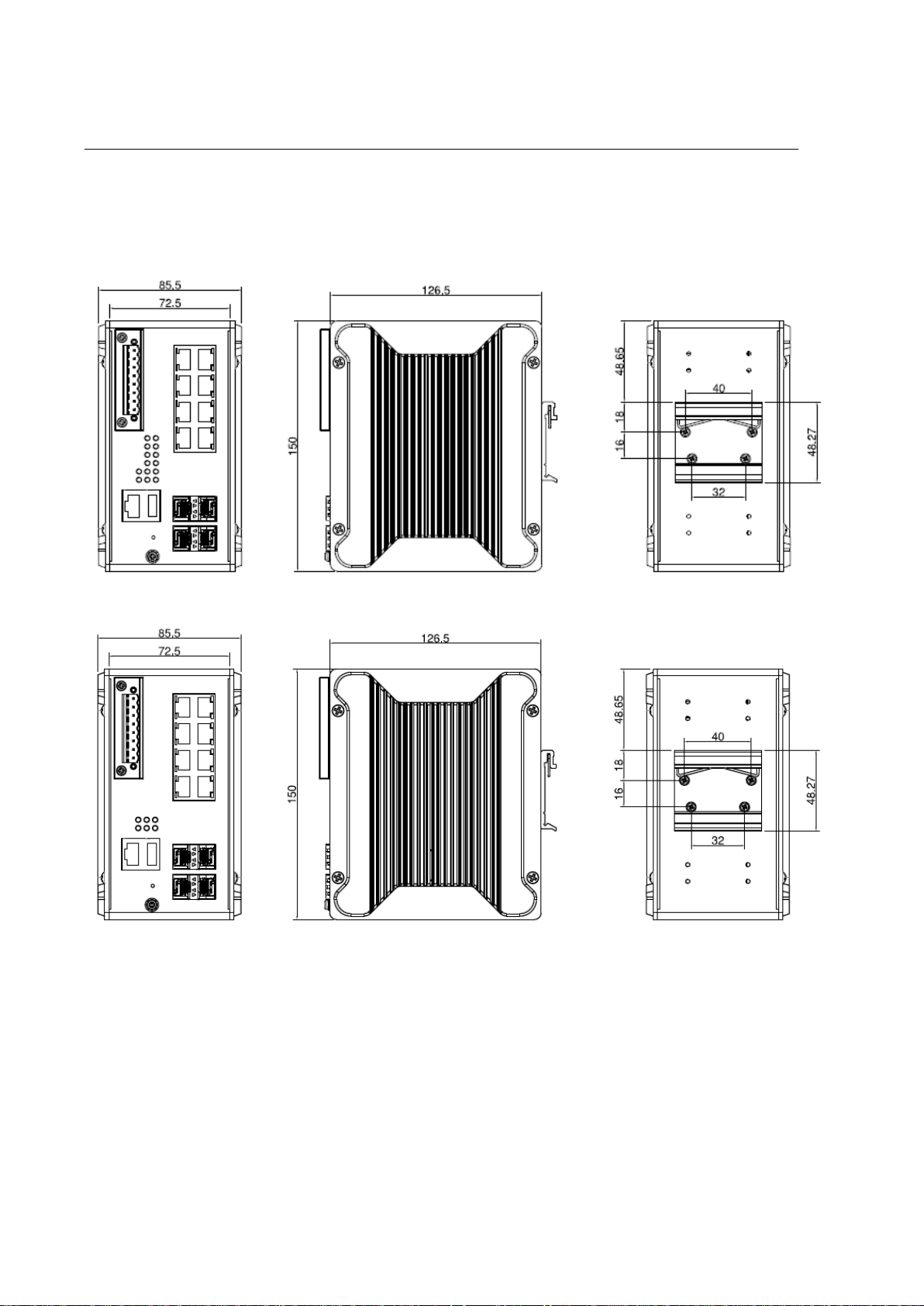
2.1 HARDWARE DIMENSION
Dimensions of DP612: 85.5 x 150 x 126.5 (W x H x D) / without DIN Rail Clip
Dimensions of DS612: 85.5 x 150 x 126.5 (W x H x D) / without DIN Rail Clip
Page 9
9
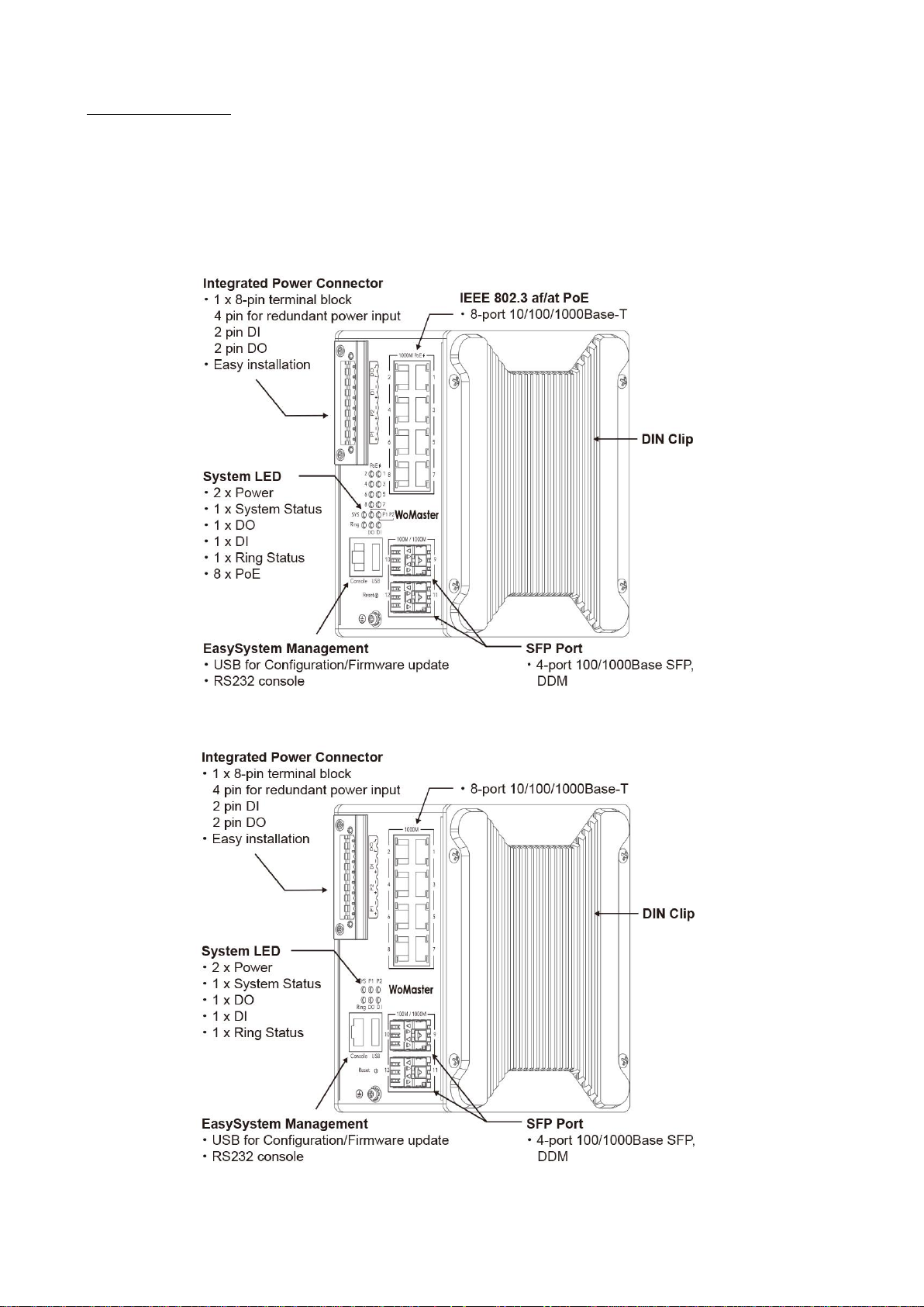
Front Panel Layout
The front panel from DP612 and DS612 switches includes 8 ports Giga Ethernet, 4 SFP ports, System LED, USB for
configuration/firmware management, RJ-45 diagnostic console, 1 x 8-pin terminal block connector (4 pin for power
inputs, 2 pin for digital input and 2 pin for alarm relay output) and 1 chassis grounding screw. The difference is for
DP612 it is provided with PoE LED. On the rear side of switch there is DIN rail clip attached.
DP612
DS612
Page 10
10
2.2 WIRING THE POWER INPUTS
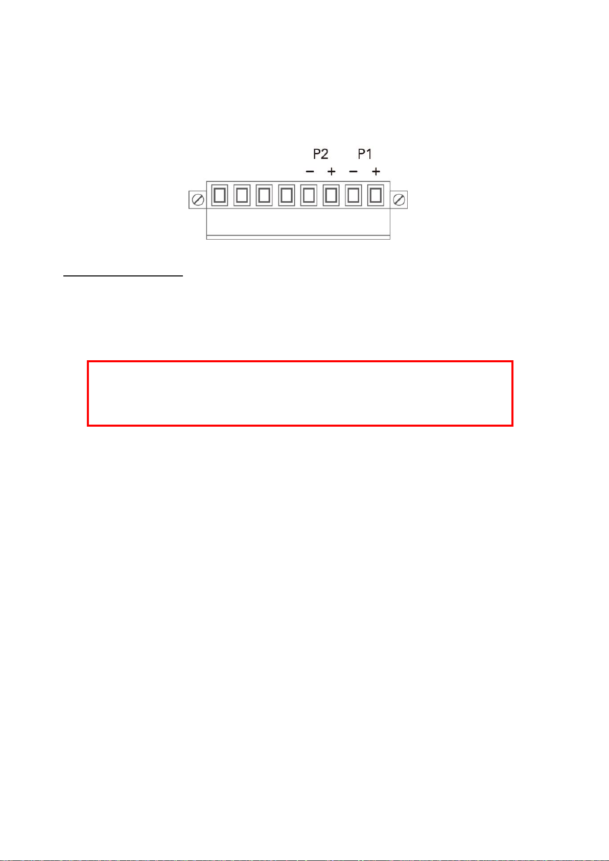
WARNING: Turn off AC power input source before connecting the Power to the terminal block
connectors, for safety purpose. Don not turn-on the source of AC/DC power before all of the
connections were well established.
Power Input port in the switch provides 2 sets of power input connections (P1 and P2) on the terminal block. x
On the picture below is the power connector.
Wiring the Power Input
1. Insert the positive and negative wires into the V+ and V- contact on the terminal block connector.
2. Tighten the wire-clamp screws to prevent the power wires from being loosened.
3. Connect the power wires to suitable AC/DC Switching type power supply. The input DC voltage should be in
the range of 46VDC to DC 57V DC (recommended to use DC 48V power supply).
Page 11
11
2.3 WIRING THE ALARM RELAY OUTPUT (DO)
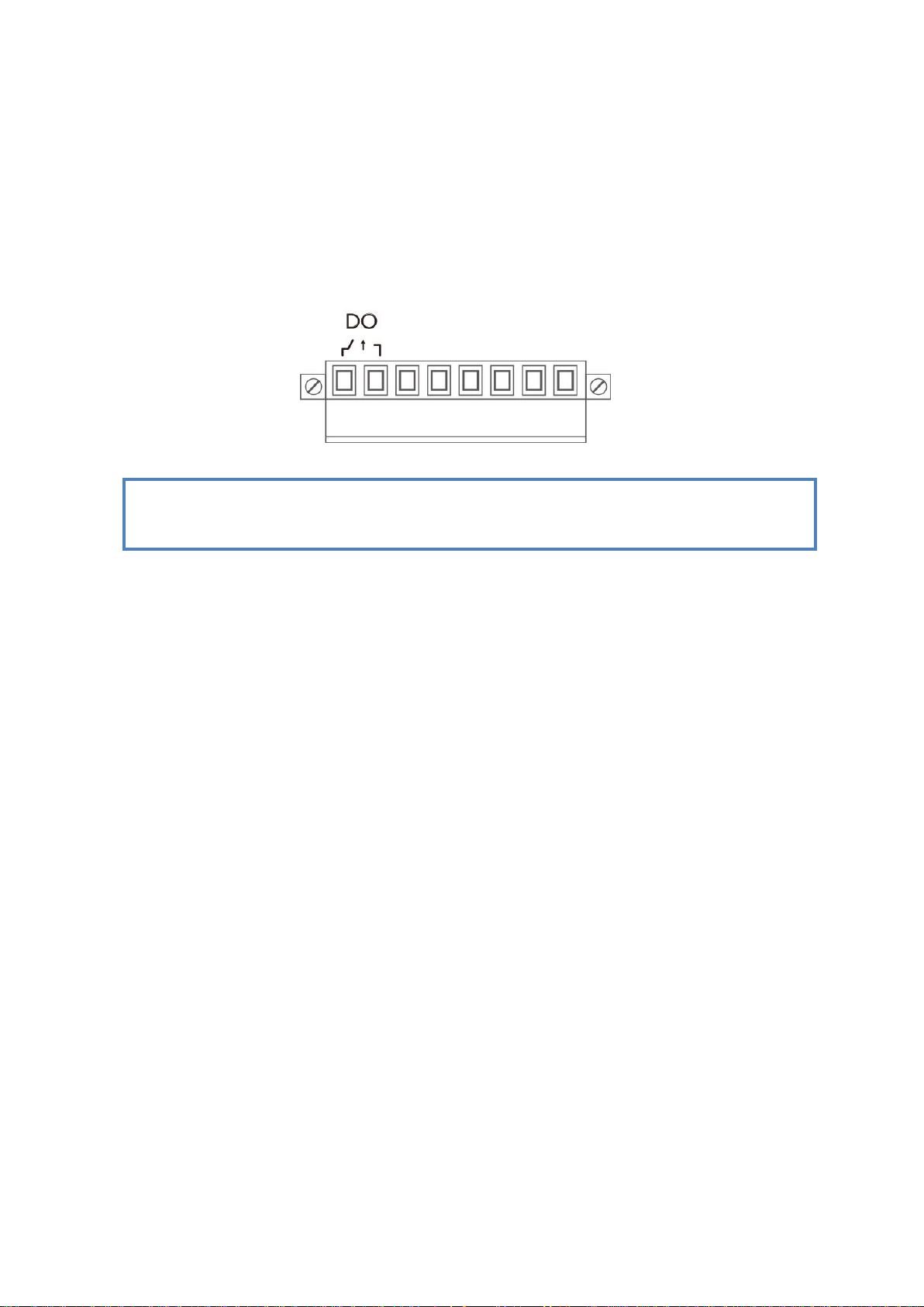
NOTE: The relay contact only supports 0.5 A current, DC 24V. Do not apply voltage and current higher
than the specifications.
The relay output contacts are located on the front panel of the switch. The relay output consists of the 2-pin
terminal block connector that used to detect user-configured events. The two wires attached to the fault contacts
form a close circuit when a user-configured event is triggered. If a user-configured event does not occur, the fault
circuit remains opened. The fault conditions such as power failure, Ethernet port link break or other pre-defined
events which can be configured in the switch. Screw the DO wire tightly after digital output wire is connected.
Page 12
12
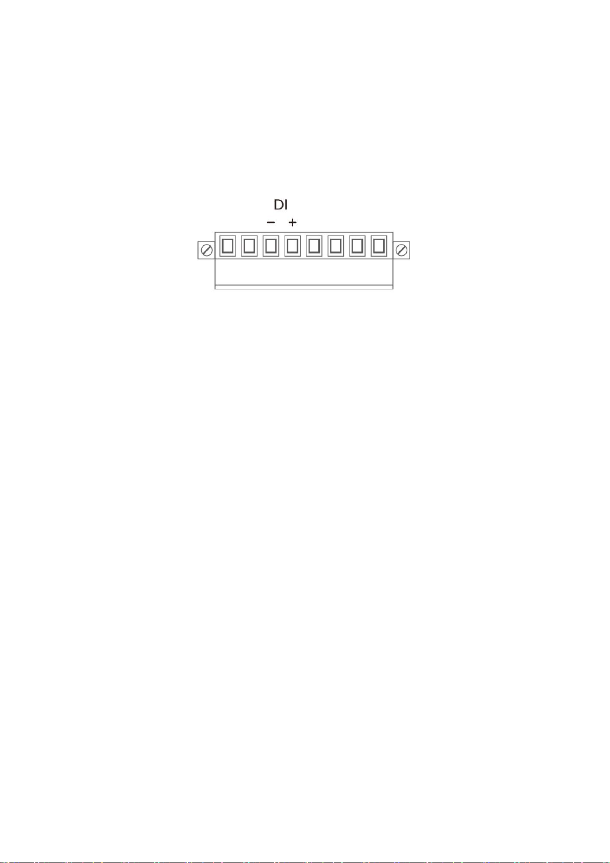
2.4 WIRING THE DIGITAL INPUT (DI)
The Digital Input accepts one external DC type signal input that consists of two contacts on the terminal block
connector on the switch’s top panel. And can be configured to send alert message through Ethernet when the signal
is changed. The signal may trigger and generated by external power switch, such as door open trigger switch for
control cabinet. The switch’s Digital Input accepts DC signal and can receive Digital High Level input DC 11V~30V and
Digital Low Level input DC 0V~10V.
Here are the steps to wire the Digital Input:
STEP 1: Insert the negative and positive wires into the -/+ terminals, respectively.
STEP 2: To keep the wires from pulling loose, tighten the wire-clamp screws on the front of the terminal block
connector.
STEP 3: Insert the terminal block connector prongs into the terminal block receptor, which is located on the switch’s
top panel.
Page 13
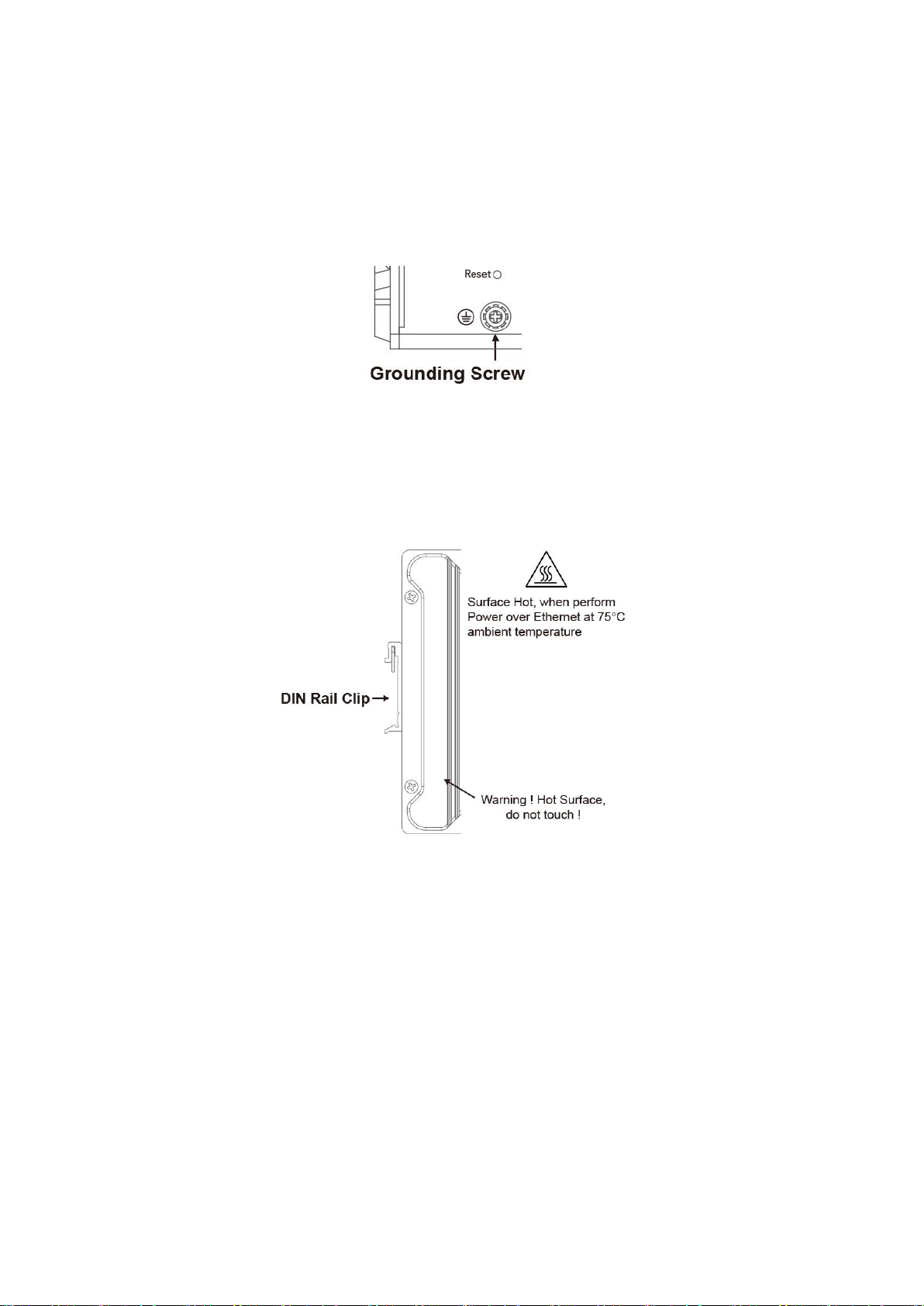
2.5 CONNECTING THE GROUDING SCREW
Grounding screw is located on the front side of the switch. Grounding Screw helps limit the effects of noise due to
electromagnetic interference (EMI) such as lighting or surge protection. Run the ground connection from the ground
screw to the grounding surface prior to connecting devices. And tighten and wire to chassis grounding for better
durability.
2.6 DIN RAIL MOUNTING
The EN50022 DIN-Rail plate should already attached at the back panel of the switch screwed tightly. If you need to
reattach the DIN-Rail attachment plate to the switch, make sure the plate is situated towards the top, as shown by the
following figures.
To mount the switch on DIN Rail track, do the following instruction:
1. Insert the top side of DIN Rail track into the slot of DIN Rail clip.
2. Lightly clip the bottom of DIN-Rail to the track and make sure it attached well.
3. To remove the switch from the track, reverse the steps.
13
Page 14

3. WEB MANAGEMENT CONFIGURATION
To access the management interface, WoMaster has several ways access mode through a network; they are web
management, console management and telnet management. Web interface management is the most common way
and the easiest way to manage a network, through web interface management, a switch interface offering status
information and a subset of switch commands through a standard web browser. If the network is down, another
alternative to access the management interface can be used. The alternative way is by using console and telnet
management which is offer configuration way through CLI Interface. WoMaster also provide excellent alternative by
configure the switch via RS232 console cable if user doesn’t attach user admin PC to the network, or if user loses
network connection to Managed Switch. This manual describes the procedures for Web Interface and how to
configure and monitor the managed switch only. For the CLI management interface please refers to the CLI
Command User Manual.
PREPARATION FOR WEB INTERFACE MANAGEMENT
WoMaster provides Web interface management that allows user through standard web-browser such as Microsoft
Internet Explorer, or Mozilla, or Google Chrome, to access and configure the switch management on the network.
1. Plug the DC power to the switch and connect switch to computer.
2. Make sure that the switch default IP address is 192.168.10.1.
3. Check that PC has an IP address on the same subnet as the switch. For example, the PC and the switch
are on the same subnet if they both have addresses that start 192.168.1.x (Ex: 192.168.10.2). The subnet
mask is 255.255.255.0.
4. Open command prompt and ping 192.168.10.1 to verify that the switch is reachable.
5. Launch the web browser (Internet Explorer or Mozilla Firefox or Google Chrome) on the PC.
6. Type http://192.168.10.1 (or the IP address of the switch). And then press Enter and the login page will
appear.
7. Type user name and the password. Default user name: admin and password: admin. Then click Login.
14
Page 15

In this Web management for Featured Configuration, user will see all of WoMaster Switch’s various configuration
menus at the left side from the interface. Through this web management interface user can configure, monitoring,
and set the administration functions. The whole information used web management interface to introduce the
featured functions. User can use all of the standard web-browser to configure and access the switch on the network.
Following topics are covered in this chapter:
3.1 System
3.2 Ethernet Port
3.3 Power over Ethernet (PoE Models only)
3.4 Redundancy
3.5 VLAN
3.6 QoS
3.7 Multicast
3.8 Routing
3.9 SNMP
3.10 Security
3.11 Warning
3.12 Diagnostics
3.13 Backup / Restore
3.14 Firmware Upgrade
3.15 Reset to Defaults
3.16 Save
3.17 Logout
3.18 Reboot
3.19 Front Panel
15
Page 16
TERMS
DESCRIPTION
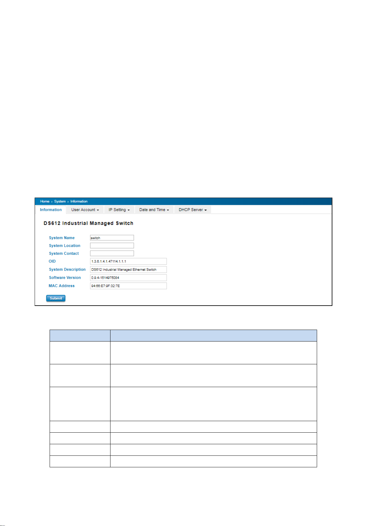
System Name
Default: switch
Set up a name to the switch device.
System Location
Default: Blank
User can specify the switch’s physical location.
System Contact
Default: Blank
User can specify the contact person here. User can type the name, mail
address or other information of the administrator.
OID
Indicates the Object ID of the switch.
System Description
Display the name of the product.
Software Version
Display the firmware latest version that installed in the device.
MAC Address
Display the hardware’s MAC address that assigned by the manufacturer.
3.1 SYSTEM
When the user login to the switch, user will see the system section appear. This section provides all the basic setting
and information or common setting from the switch that can be configured by the administrator.
Following topics is included:
2.1.1 Information
2.1.2 User Account
2.1.3 IP Setting
2.1.4 Date and Time
2.1.5 DHCP Server
3.1.1 INFORMATION
Information section, this section shows the basic information from the switch to make it easier to identify different
switches that are connected to User network. The figure below shows the interface of the Information section.
The description of the Information’s interface is as below:
16
Page 17
TERMS
DESCRIPTION
Name
Default: admin
Key in new user name here.
New Password
Default: admin
Key in new password here.
Confirm Password
Re-type the new password again to confirm it.
NOTE: For any kind of changes in configuration settings always remember to click on Save to save
the settings. Otherwise, all of settings User has made will be lost when the switch is powered off or
restarted.
NOTE: For security consideration, please change the password after first log in.
After finish the configuration, click on Submit to apply User settings.
3.1.2 USER ACCOUNT
WoMaster’ switch supports the management accounts; with the Name default setting is admin and the authority
allow user to configure all of configuration parameters. Below is the User Account section that consists of two
interfaces, Local User and Radius Interface.
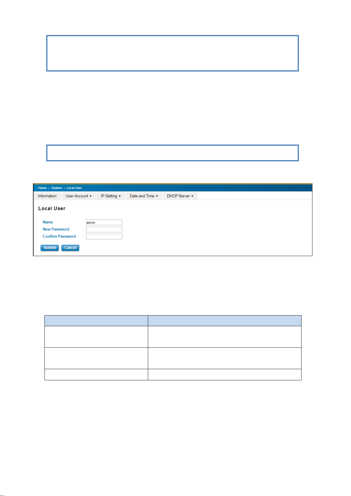
3.1.2.1 LOCAL USER
The Local User interface describes how to configure the system user name and password for the web management
login. To change the Name and Password, user just needs to input a new Name and New Password then confirm the
new password in this Local User section. After finished, click Submit to apply the changes. Don’t forget to Save the
settings. Try to re-login with the new User Name and Password.
The description of the Local User interface is as below:
After finished setting up the User Name and Password, click on Submit to apply the configuration.
17
Page 18
TERMS
DESCRIPTION
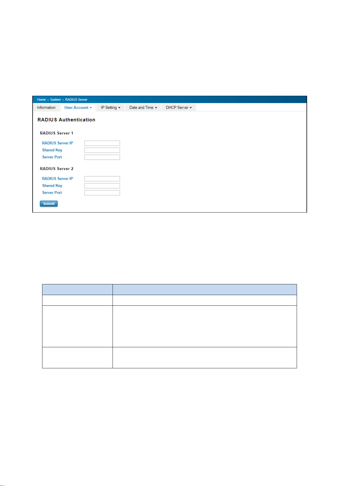
RADIUS Server IP
Radius Server IP Address
Shared Key
Shared key are used to verify that RADIUS messages, with the exception of
the Access-Request message, are sent by a RADIUS-enabled device that is
configured with the same shared key. Shared key also verify that the
RADIUS message has not been modified in transit (message integrity).
Server Port
Set communication port of an external RADIUS server as the authentication
database. The general value is 1812
3.1.2.2 RADIUS SERVER
The Remote Authentication Dial In User Service (RADIUS) mechanism is a centralized “AAA” (Authentication,
Authorization and Accounting) system for connecting to network services. The fundamental purpose of RADIUS is to
provide an efficient and secure mechanism for user account management. RADIUS server system allows you to
access the switch through secure networks against unauthorized access.
How to set up a RADIUS server:
a. Enter the IP address of the RADIUS server in Server IP Address
b. Enter the Shared Secret of the RADIUS server
c. Enter the Server port if necessary, by default RADIUS server listens to port 1812
d. Click Submit
The description of the RADIUS Authentication interface is as below:
18
Page 19
TERMS
DESCRIPTION
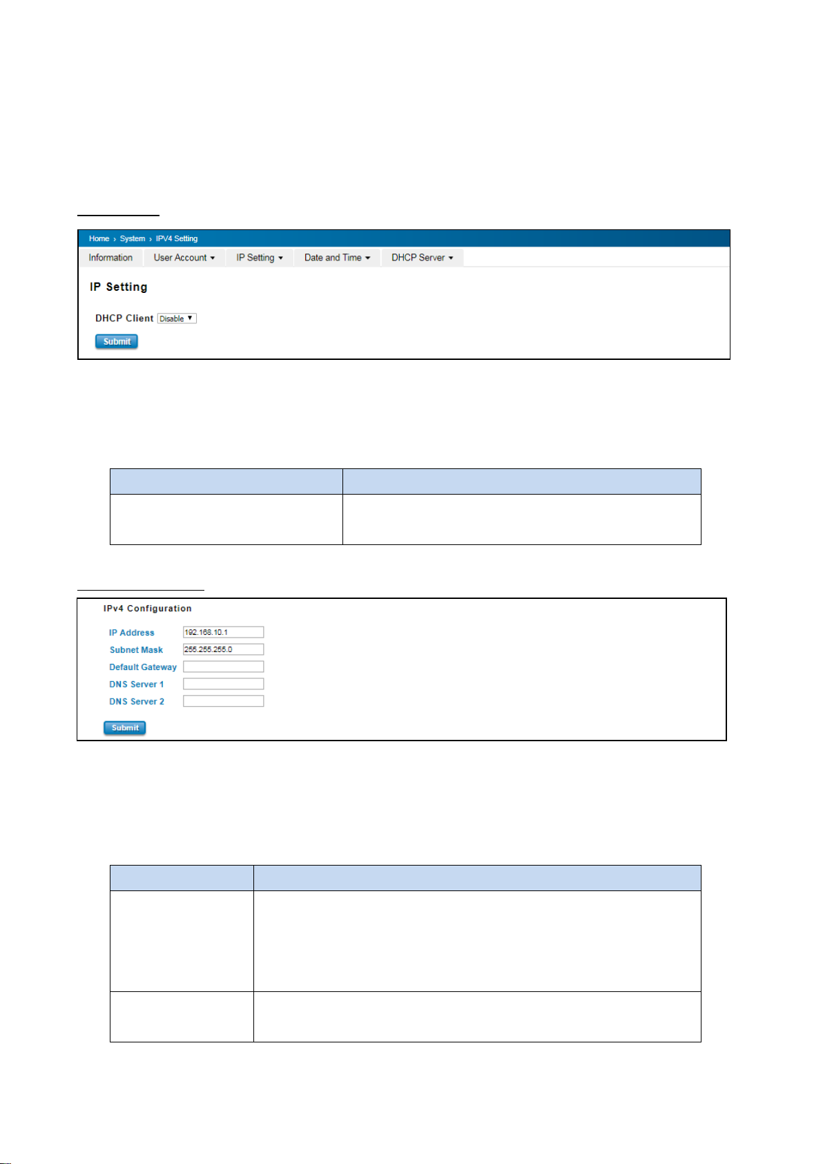
DHCP Client
Select to Enable or Disable to activate or deactivate the
DHCP Client function.
TERMS
DESCRIPTION
IP Address
Default: 192.168.10.1
Set up the IP address reserved by User network for User switch. If DHCP
Client function is enabled, no need to assign an IP address to switch as it will
be overwritten by DHCP server and shown here.
Subnet Mask
Default: 255.255.255.0
Assign the subnet mask for the IP address here. If DHCP Client function is
3.1.3 IP SETTING
IP Setting section allows users to configure both IPv4 and IPv6 values for management access over the network.
WoMaster switch supports both IPv4 and IPv6, and can be managed through either of these address types.
3.1.3.1 IPv4
DHCP Client
When DHCP Client function is enabled, an IP address will be assigned to the switch from the network’s DHCP server.
In this mode, the default IP address will be replaced by the one assigned by DHCP server. If DHCP Client is disabled,
the configured IP settings will be used. The DHCP client will announce the configured System Name as hostname to
provide DNS lookup. The description of the columns is as below:
IPv4 Configuration
The IPv4 Configuration includes the switch’s IP address and subnet mask, as well as the IP address of the default
gateway. In addition, input cells are provided for the IP addresses of a 1st and 2nd DNS server. Configure the
managed switch’s IP settings. The figure below shows the user interface of IPv4 Configuration.
The description of the columns is as below:
19
Page 20
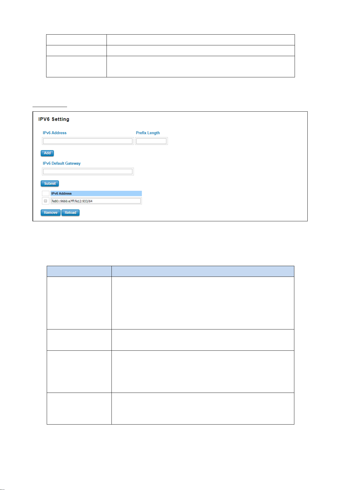
enabled, no needs to assign the subnet mask.
Default Gateway
Assign the gateway for the switch here.
DNS Server 1, DNS
Server 2
Specifies the IP address of the DNS server 1 and 2 that used in user network.
TERMS
DESCRIPTION
Ipv6 Address
Add the IPv6 address. The network portion of the address can be
configured by specifying the Prefix and using a EUI-64 interface ID in the
low order 64 bits. The host portion of the address is automatically
generated using the modified EUI-64 form of the interface identifier
(Switch’s MAC address).
Prefix Length
The size of subnet or netwok, and it equivalent to the subnetmask, but
written in different. Then click Add to apply new address to the system.
Ipv6 Default Gateway
The prefix value must be formatted according to the RFC 2373 “IPv6
Addressing Architecture,” using 8 colon-separated 16-bit hexadecimal
values. One double colon may be used in the address to indicate the
appropriate number of zeros required to fill the undefined fields.
Ipv6 Address
The default IP address of the Switch: fe80::212:77ff:feff:1acb/64
Select existed Ipv6 address and click Remove to delete IP address. Click
Reload to refresh and reload list.
3.1.3.2 IPv6
IPv6 Setting
An Ipv6 address is represented as eight groups of four hexadecimal digits, each group representing 16 bits (two
octets).The groups are separated by colons (the length of Ipv6 address is 128bits. An example of an Ipv6 address is:
fe80::212:77ff:feff:1acb/64.
The description of the columns is as below:
20
Page 21
TERMS
DESCRIPTION
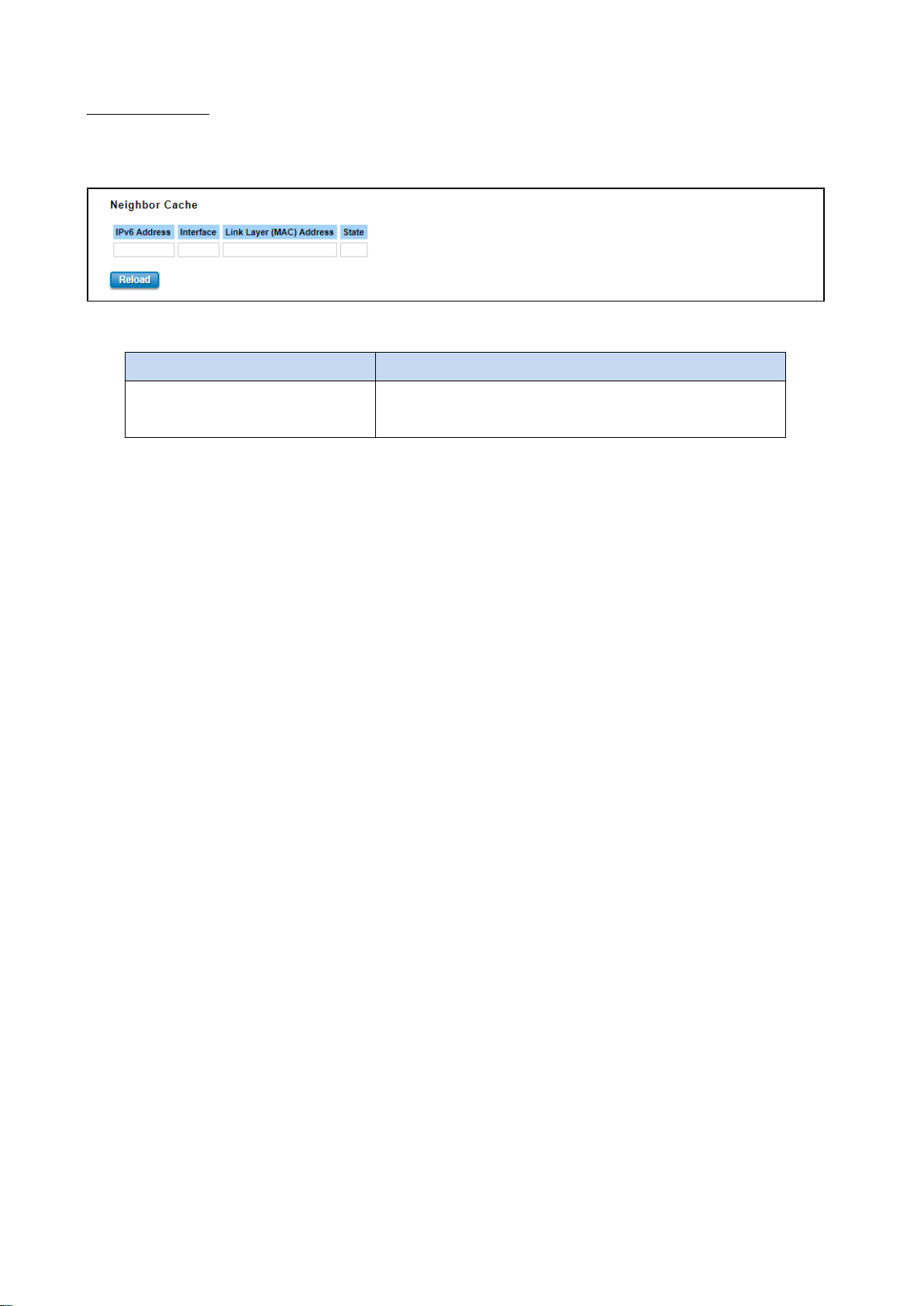
Neighbor Cache
The system will update Neighbor Cache automatically, and
user also can click Reload to refresh the table.
Neighbor Cache
The IPv6 neighbor table includes the neighboring node’s IPv6 address, Interface, MAC Address, and the current state
of the entry.
The description of the columns is as below:
21
Page 22
TERMS
DESCRIPTION
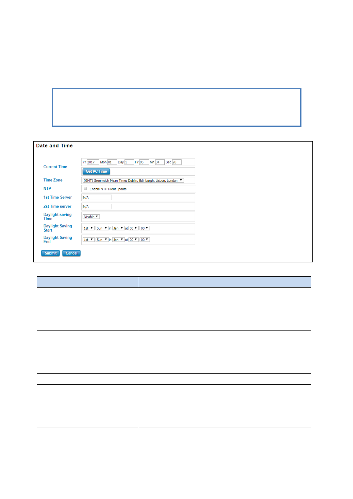
Current Time
User can configure time by input it manually. User also can click the
Get Time from PC to get PC’s time setting.
Time Zone
Choose the Time Zone section to adjust the time zone based on the
user area.
NTP
Enable NTP Client update by checking this box. The system will send
request packet to acquire current time from the NTP server that
assigned.
*Make sure that the switch also has the internet connection.
1st Time Server & 2nd Time Server
Choose from NTP Server List, to adjust User system time.
Daylight Saving Time
Enable the Daylight Saving Function and the setting of function start
and end time or disable it.
Daylight Saving Start & Daylight
Saving End
Allows user to sets the Start and End time individually.
NOTE: The WoMaster’ switch does not have a real-time clock. The user must update the Current
Time to set the initial time for the WoMaster’ switch after each reboot, especially when there is no
NTP server on the LAN or Internet connection.
3.1.4 DATE AND TIME
3.1.4.1 DATE AND TIME SETTING
The WoMaster’ switch has a time calibration function based on information from an NTP server or user specified
time and date, allowing functions such as automatic warning emails to include a time and date stamp.
The description of the columns is as below:
After finished configuring, click on Submit to activate the configuration.
22
Page 23

IEEE 1588 PTP
IEEE 1588
IEEE 1588 was published in 2002, expands the performance capabilities of Ethernet networks to control systems that
operate over a communication network. In recent years an increasing number of electrical power systems have been
using a more distributed architecture with network technologies that have less stringent timing specifications. IEEE
1588 generates a master-slave relationship between the clocks, and enforces the specific timing requirements in
such power systems. All devices ultimately get their time from a clock known as the grandmaster clock. In its basic
form, the protocol is intended to be administration free.”
How Does an Ethernet Switch Affect 1588 Synchronization?
An Ethernet switch potentially introduces multi-microsecond fluctuations in the latency between the 1588
grandmaster clock and a 1588 slave clock. When these fluctuations are incorrect, it will cause synchronization errors.
The magnitude of these fluctuations depends on the design of the Ethernet switch and the details of the
communication traffic. Experiments with prototype implementations of IEEE 1588 indicate that with suitable care
the effect of these fluctuations can be successfully managed. For example, use of appropriate statistics in the 1588
devices to recognize significant fluctuations and use suitable averaging techniques in the algorithms controlling the
correction of the local 1588 clock will be good design means to achieve the highest time accuracy.
Can Ethernet switches be designed to avoid the effects of these fluctuations?
A switch can be designed to support IEEE 1588 while avoiding the effects of queuing. In this case two modifications
to the usual design of an Ethernet switch are necessary:
1. The Boundary Clock and Transparent Clock functionalities defined by IEEE 1588 must be implemented in the
switch.
2. The switch must be configured so that it does not pass IEEE 1588 message traffic using the normal communication
mechanisms of the switch.
Such an Ethernet switch will synchronize clocks directly connected to one of its ports to the highest possible
accuracy.
The main function of IEEE 1588 is to synchronize the clocks of different end devices over a network at speeds faster
than one Micro-second. After time synchronized, the system time will display the correct time of the PTP server.
23
Page 24
TERMS
DESCRIPTION
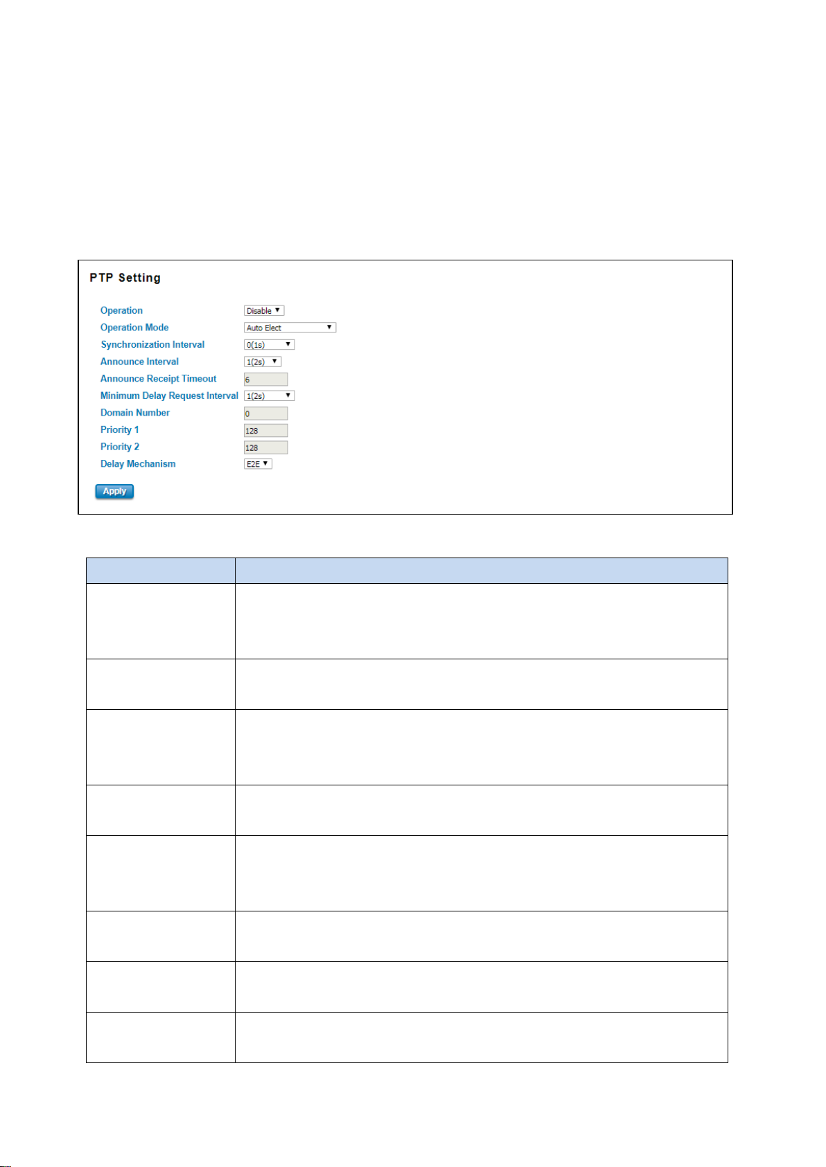
Operation
Default: Disable
Enable/Disable the PTP function. This is the main option that needs to be enabled so
that the PTP function will work
Operation Mode
Default: Auto Elect
Choose Mode (Auto Elect, Preferred Master Clock or Slave)
Synchronization
Interval
Default: 0 (1s)
Set the interval of the sync packet transmitted time. Small interval causes too
frequent sync, which will cause more load to the device and network.
Announce Interval
Default: 1 (2s)
Sets the announce message interval
Announce Receipt
Timeout
Default: 6
The multiple of announce message receipt timeout by the announce message
interval.
Minimum Delay
Request Interval
Default: 1 (2s)
Minimal delay request message interval
Domain Number
Subdomain name (IEEE 1588-2002) or the domain Number (IEEE 1588-2008) fields in
PTP messages
Priority 1
Default: 128
Set the clock priority 1 (PTP version 2). The lower values take precedence to be
3.1.4.2 PTP SETTING
The PTP can be set in this PTP Setting webpage in which the user can configure PTP. The top part of this figure allows
the users to enable or disable the PTP function. To enable PTP on the managed switch, please choose Enable. Note
that the PTP functions will not active if the Operation is disabled. Please see description of PTP Setting in table
description. Note that after setting the desired PTP Setting, please click Apply button to allow the configuration take
effect.
The description of the columns is as below:
24
Page 25
selected as the master clock in the best master clock algorithm, 0 = highest priority,
255 = lowest priority.
Priority 2
Default: 128
Set the clock priority 2 (PTP version 2). The lower values take precedence to be
selected as the master clock in the best master clock algorithm (BMCA), 0 = highest
priority, 255 = lowest priority.
Delay Mechanism
Default: E2E
Configures the delay mechanism in boundary clock mode.
E2E - The delay request or response mechanism used in the boundary clock mode.
P2P - The peer-to-peer mechanism used in the boundary clock mode
3.1.5 DHCP SERVER
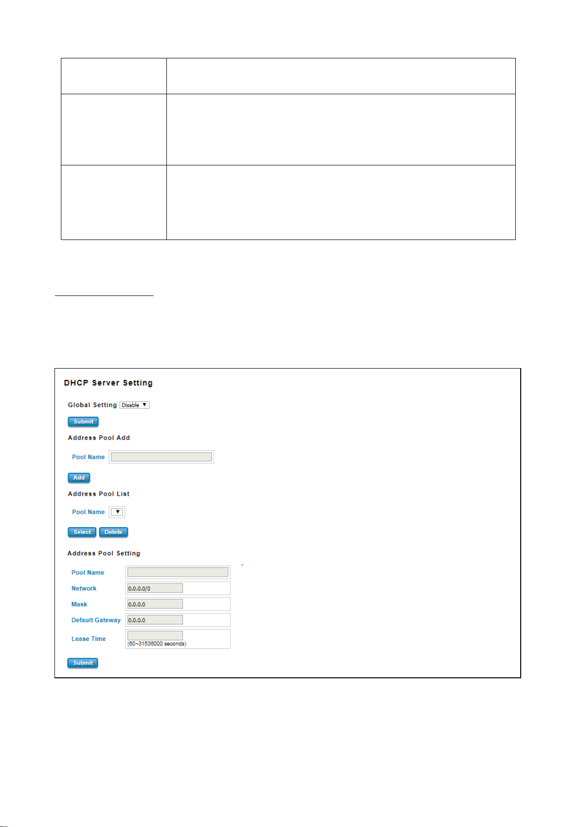
DHCP Server Setting
WoMaster’ switch has DHCP Server Function that will provide a new IP address to DHCP Client. After enable DHCP
Server function, set up the Network IP address for the DHCP server IP address, Subnet Mask, Default Gateway
address and Lease Time for client. Below is the DHCP Server Setting interface
25
Page 26
TERMS
DESCRIPTION
Global Setting
Select to Enable or Disable to activate and deactivate DHCP Server function.
Address Pool Add
Add address pool to local DHCP Server
Address Pool List
Choose the address pool setting that has been entered
Network
Enter the starting IP addresses for the DHCP server’s IP assignment.
Mask
Assign the subnet mask for the IP address here.
Default Gateway
Enter the ending IP addresses for the DHCP server’s IP assignment.
Lease Time
The maximum length of time for the IP address lease. Enter the Lease time in
minutes. (Lease Time range: 60-31536000 seconds)
TERMS
DESCRIPTION
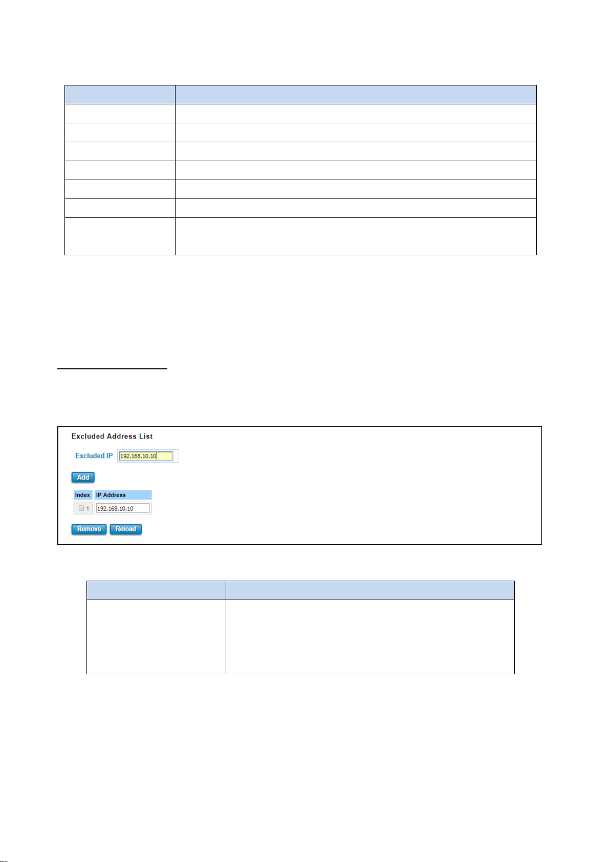
Excluded Address List
Type a specific address into the Excluded IP field for the DHCP
server reserved IP address. Then click Add, to remove an IP
address from the list click Remove. To refresh the list, click
Reload.
The description of the columns is as below:
The DHCP Server will automatically assign an IP address to the computers on the LAN/private network. Be sure to set
user computers to be DHCP clients by setting their TCP/IP settings to “Obtain an IP Address Automatically.” When
user turns the computers on, they will automatically load the proper TCP/IP settings provided by the switch. If User
manually assigns IP addresses to User computers or devices, make sure the IP addresses are outside of this range or
User may have an IP conflict. After finished configuring, click on Submit to activate the configuration.
Excluded Address List
The figure below shows the Excluded Address List, the IP address that is listed in the Excluded Address List table will
not be assigned to the network devices.
The description of the columns is as below:
26
Page 27
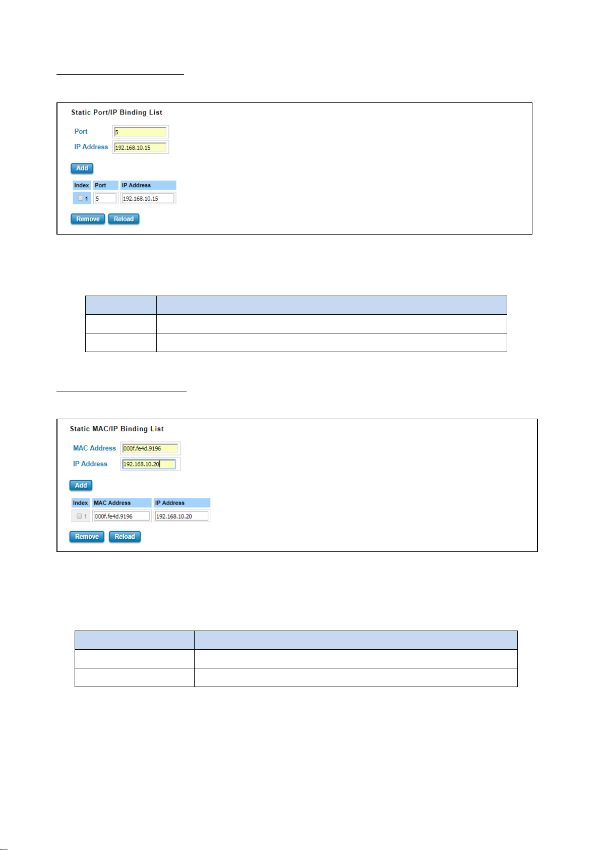
TERMS
DESCRIPTION
Port
The port that wishes binding.
IP Address
The IP address that will assign to the device with the Binding MAC address.
TERMS
DESCRIPTION
MAC Address
The MAC address of the device that wishes binding.
IP Address
The IP address that will assign to the device with the Binding MAC address.
Static Port/IP Binding List
The figure below is the web interface for Static Port/IP Binding List.
Type the specific Port and IP address, and then click Add to add a new Port & IP address binding rule for a specific
client. The description of the columns is as below:
To remove from the binding list, select the index and click Remove. To refresh the list, click Reload.
Static MAC/IP Binding List
The figure below is the web interface for Static MAC/IP Binding List.
Type the specific MAC and IP address, and then click Add to add a new MAC & IP address binding rule for a specific
client.
The description of the columns is as below:
To remove from the binding list, select the index and click Remove. To refresh the list, click Reload.
27
Page 28
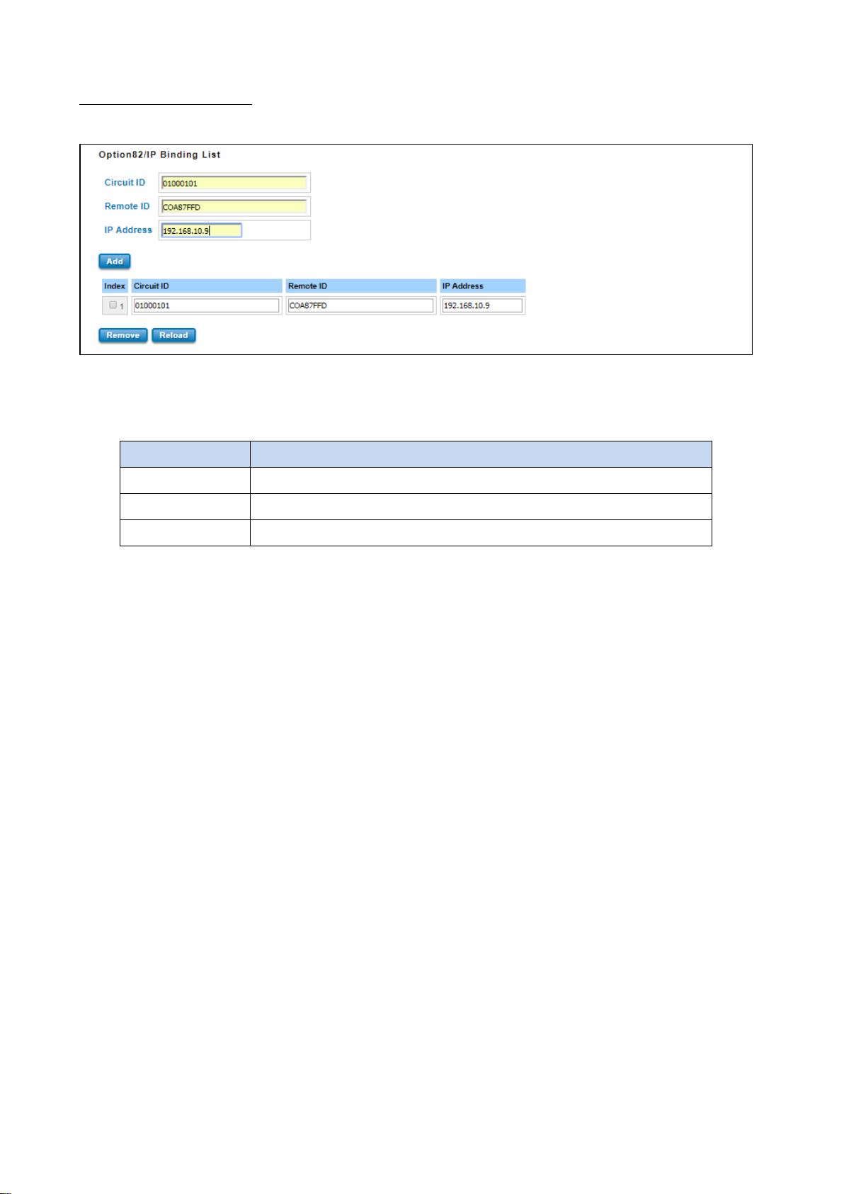
TERMS
DESCRIPTION
Circuit ID
The Circuit ID of the device that wishes binding.
Remote ID
The Remote ID of the device that wishes binding.
IP Address
The IP address that will assign to the device with the Binding MAC address.
Option 82/IP Binding List
The figure below is the web interface for Option 82/IP Binding List.
Type the specific Circuit ID, Remote ID and IP address, and then click Add to add a new binding rule for a specific
client.
The description of the columns is as below:
To remove from the binding list, select the index and click Remove. To refresh the list, click Reload.
28
Page 29
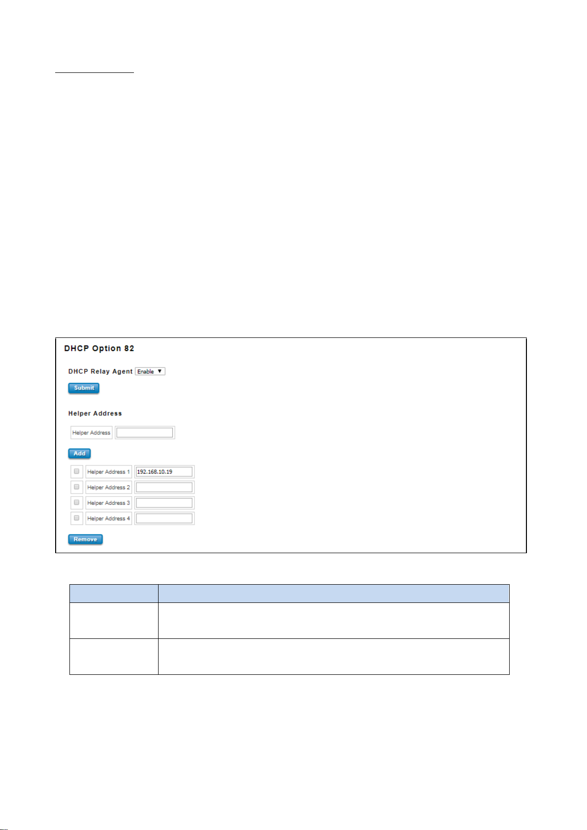
TERMS
DESCRIPTION
DHCP Option 82
Select to Enable or Disable to activate or deactivate DHCP relay agent function, and
then select the modification type of option 82.
Helper Address
There are 4 fields for the DHCP server’s IP address. Fill the field with preferred IP
address of DHCP Server.
DHCP Option 82
The DHCP Relay Agent (or DHCP Option 82) makes it possible for DHCP broadcast messages to be sent over routers.
The DHCP Relay Agent enables DHCP clients to obtain IP addresses from a DHCP server on a remote subnet, or those
that are not located on the local subnet.
DHCP Option 82 is used by the relay agent to insert additional information into the client’s DHCP request. The Relay
Agent Information option is inserted by the DHCP relay agent when forwarding client-originated DHCP packets to a
DHCP server. Servers can recognize the Relay Agent Information option and use the information to implement IP
addresses to Clients.
When DHCP Option 82 is enabled on the switch, a subscriber device is identified by the switch port through which it
connects to the network (in addition to its MAC address). Multiple hosts on the subscriber LAN can be connected to
the same port on the access switch and are uniquely identified.
The Option 82 information contains 2 sub-options, Circuit ID and Remote ID, which define the relationship between
the end device IP and the DHCP Option 82 server. The Circuit ID is a 4-byte number generated by the Ethernet
switch—a combination of physical port number and VLAN ID.
The description of the columns is as below:
And click Submit to activate the DHCP relay agent function. All the DHCP packets from client will be modified by the
policy and forwarded to DHCP server through the gateway port. When Option 82 is enabled on the switch, a
subscriber device is identified by the switch port through which it connects to the network (in addition to its MAC
address).
29
Page 30
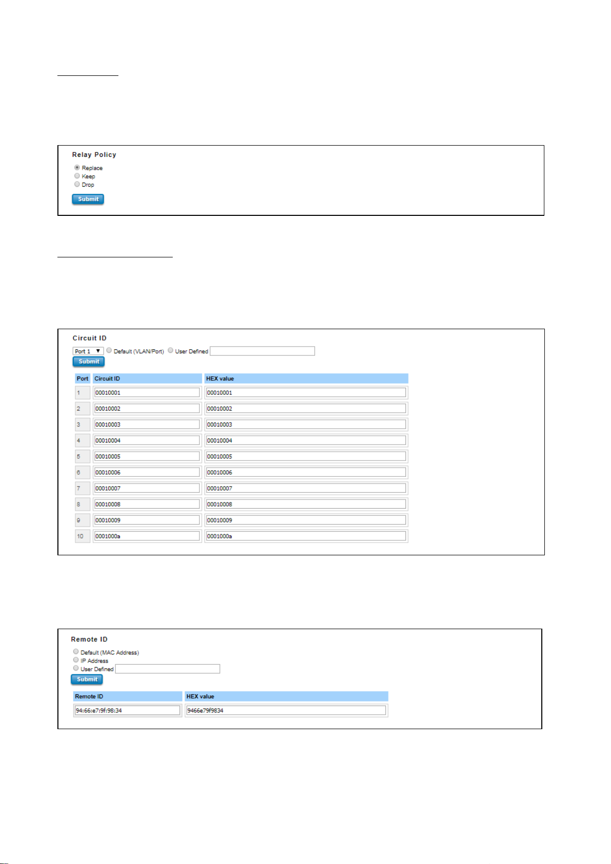
Relay Policy
Replace - Replaces the existing option 82 field and adds new option 82 field. (This is the default setting).
Keep - Keeps the original option 82 field and forwards to server.
Drop - Drops the option 82 field and do not add any option 82 field.
Circuit ID & Remote ID
The DHCP Option 82 information also contains 2 sub-options, Circuit ID and Remote ID, which define the
relationship between the end device IP and the DHCP Option 82 server. The Circuit ID is a 4-byte number generated
by the Ethernet switch. To activate this section, please make sure that DHCP Relay Agent is enabled.
The format of the Circuit ID is shown above: 00–01–00–01, this is where the first byte is “00”, the second and the
third byte “01-00” is formed by the port VLAN ID, and the last byte “01” is formed by the port number. For example:
00–01–00–01 is the Circuit ID of port number 1 with port VLAN ID 1.
The Remote ID identifies the relay agent itself and can be one of the following:
1. The IP address of the relay agent.
30
Page 31
TERMS
DESCRIPTION
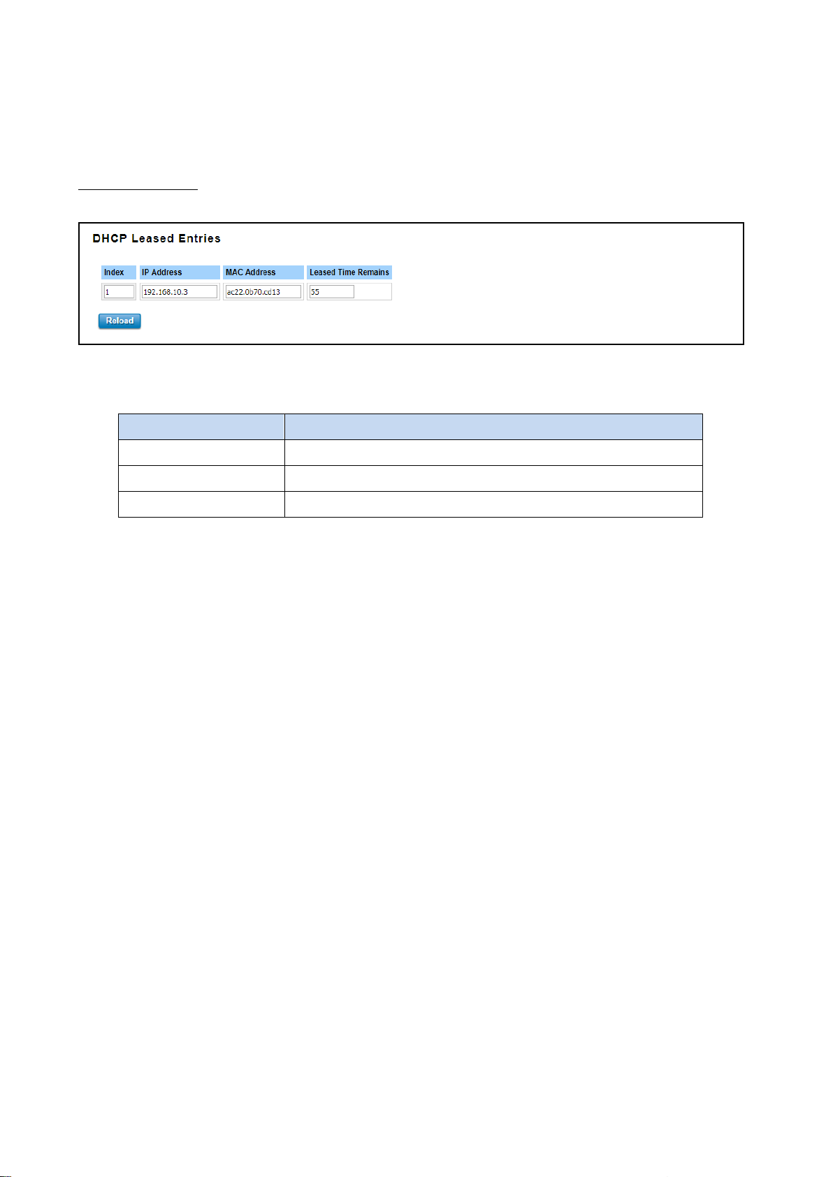
IP Address
IP address that was assigned by switch.
MAC Address
MAC address that was assigned by switch.
Leased Time Remains
Remains time for the IP address leased
2. The MAC address of the relay agent.
3. A combination of IP address and MAC address of the relay agent.
4. A user-defined string.
DHCP Leased Entries
The figure below shows the DHCP Leased Entries. It will show the MAC and IP address that was assigned by switch.
Click the Reload button to refresh the list.
The description of the columns is as below:
31
Page 32
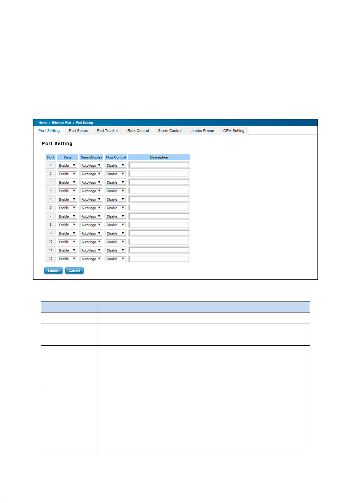
TERMS
DESCRIPTION
Port
Shows port number
State
Default: Enable
Enable or disable a port
Speed/Duplex
Default: AutoNegotiation
Users can set the bandwidth of each port as Auto-negotiation, 100 full,100 half,10
full,10 half mode for Giga Ethernet Port 1~8 (ge1~ge8). For Gigabit Ethernet Port
9~12: (ge9~ge12), it can be set up to 100M Full Duplex(100 Full) only.
Flow Control
Default: Disable
Enable means that User need to activate the flow control function in order to let the
flow control of that corresponding port on the switch to work. Disable means that
User doesn’t need to activate the flow control function, as the flow control of that
corresponding port on the switch will work anyway.
Description
The description of interface.
3.2 ETHERNET PORT
Ethernet Port section is used to access the port configuration and rate limit control. It also allows User to view port
status and port trunk information.
3.2.1 PORT SETTING
Port Settings section allows users to enable or disable each port function; state the speed/duplex of each port; and
enable or disable the flow control of the port.
The description of the columns is as below:
32
Page 33
After finished configuring the settings, click on Submit to save the configuration.
3.2.2 PORT STATUS
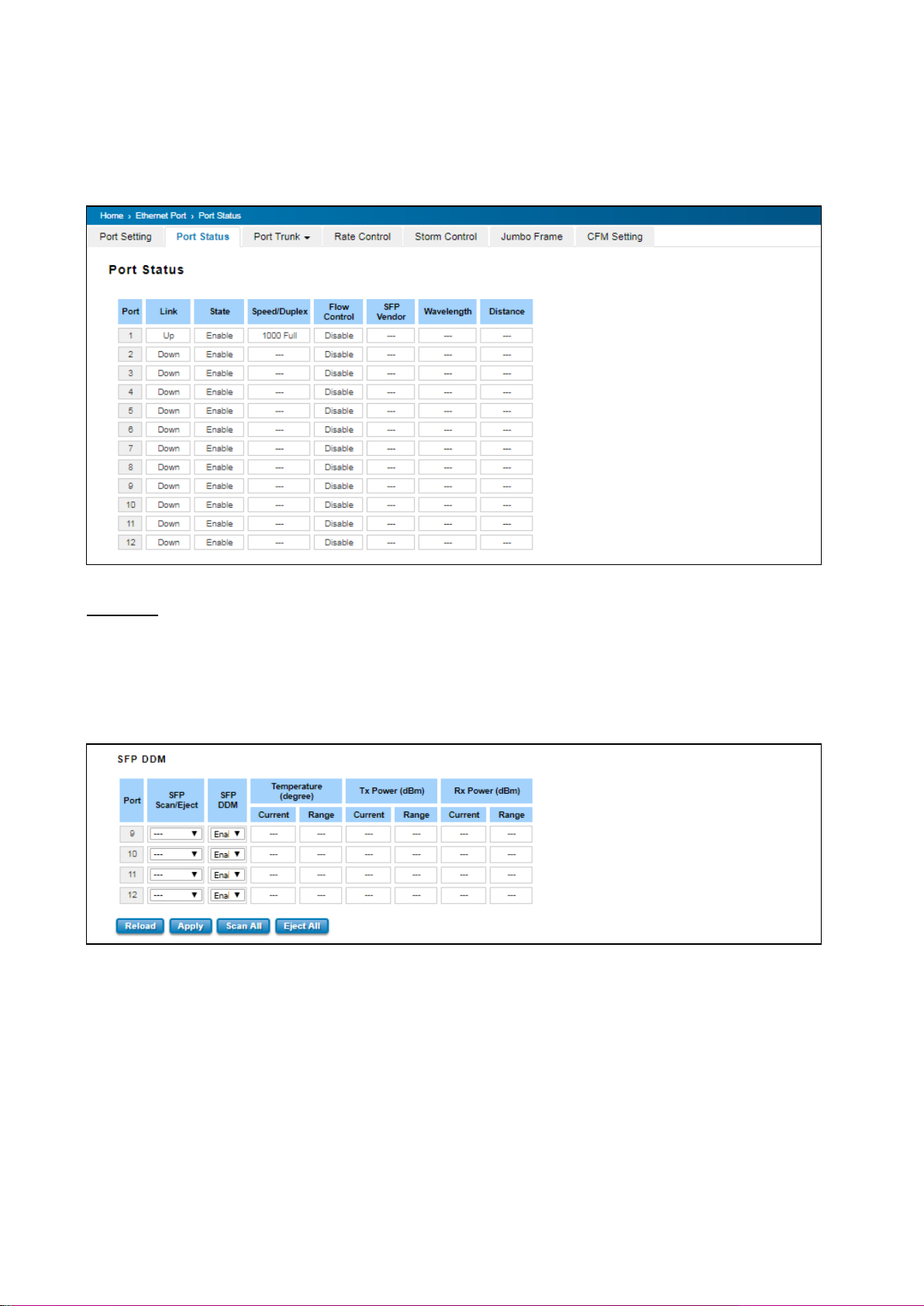
Port Status provides current port status.
SFP DDM
WoMaster’ Industrial Switch supports the SFP module with digital diagnostics monitoring (DDM) function. User can
check the physical or operational status of an SFP module via SFP DDM section. This section shows and configures
the operational status, such as Scan/Eject the SFP, Enable/Disable SFP DDM, Temperature degree, Tx Power statistics,
Rx Power Statistics in real time.
33
Page 34

TERMS
DESCRIPTION
SFP Scan/Eject
Scan the SFP module or Eject the SFP module.
SFP DDM
Enable/Disable the DDM function.
Temperature
The specific temperature range and current temperature
detected of DDM SFP transceiver.
Tx Power (dBm)
The range and current transmit power of DDM SFP
transceiver.
Rx Power (dBm)
The range and current received power of DDM SFP
transceiver.
The description of the Port Status and SFP DDM columns is as below:
Click Reload to reload the all port information, click Scan All to scan the SFP transceiver module and display the
statistics. Eject All to eject the SFP transceiver that User has selected or plugged. User can eject one port or eject all
by click the Eject All button. Click Apply to apply the configuration that just made.
3.2.3 PORT TRUNK
Port Trunk, also called “Link Aggregation”, is a method of combining multiple network connections in parallel to
increase throughput beyond what a single connection could sustain. The aggregated ports can be viewed as one
physical port so that the bandwidth is higher than merely one single Ethernet port. The member ports of the same
trunk group can balance the loading and backup for each other. WoMaster’ industrial managed switches support 2
types of Port Trunk. One is LACP (dynamic) and the other is Static. Link Aggregation Control Protocol (LACP), which is
a protocol running on layer 2, provides a standardized means in accordance with IEEE 802.3ad to bundle several
physical ports together to form a single logical channel. LACP mode is more flexible, and it can change modes, either
trunk or single port. Dynamic Port Trunk also provides a redundancy function, in case one of the links fails. If one of
the trunk members has failed, it will still work well in LACP mode, but it will link down if using static mode. All the
ports within the logical channel or so-called logical aggregator work at the same connection speed and LACP
operation requires full-duplex mode. Static mode is still necessary, because some devices only support static trunk.
Port Trunk Concept
Port trunking protocol that provides the following benefits:
• Flexibility in setting up User network connections, since the bandwidth of a link can be doubled, tripled, or
quadrupled.
• Redundancy—if one link is broken, the remaining trunked ports share the traffic within this trunk group.
• Load sharing—MAC client traffic can be distributed across multiple links.
To avoid broadcast storms or loops in User network while configuring a trunk, first disable or disconnect all ports
that User want to add to the trunk or remove from the trunk. After User finish configuring the trunk, enable or
re-connect the ports.
If all ports on both switch units are configured as 100BaseTX and they are operating in full duplex mode, this means
that users can double, triple, or quadruple the bandwidth of the connection by port trunk between two switches.
When User activates port trunk, certain settings on each port will be reset to factory default values or disabled:
• Communication redundancy will be reset.
34
Page 35
TERMS
DESCRIPTION
Group ID
Default: 0
Group ID is the ID for the port trunk group. Ports with same group ID
are in the same group.
Type
Default: Blank
Static and LACP. Each Trunk Group can only support Static or LACP.
Choose the type User need here.
• 802.1Q VLAN will be reset.
• Multicast Filtering will be reset.
• Port Lock will be reset and disabled.
• Set Device IP will be reset.
• Mirror will be reset.
After port trunk has been activated, User can configure these items again for each trunk port.
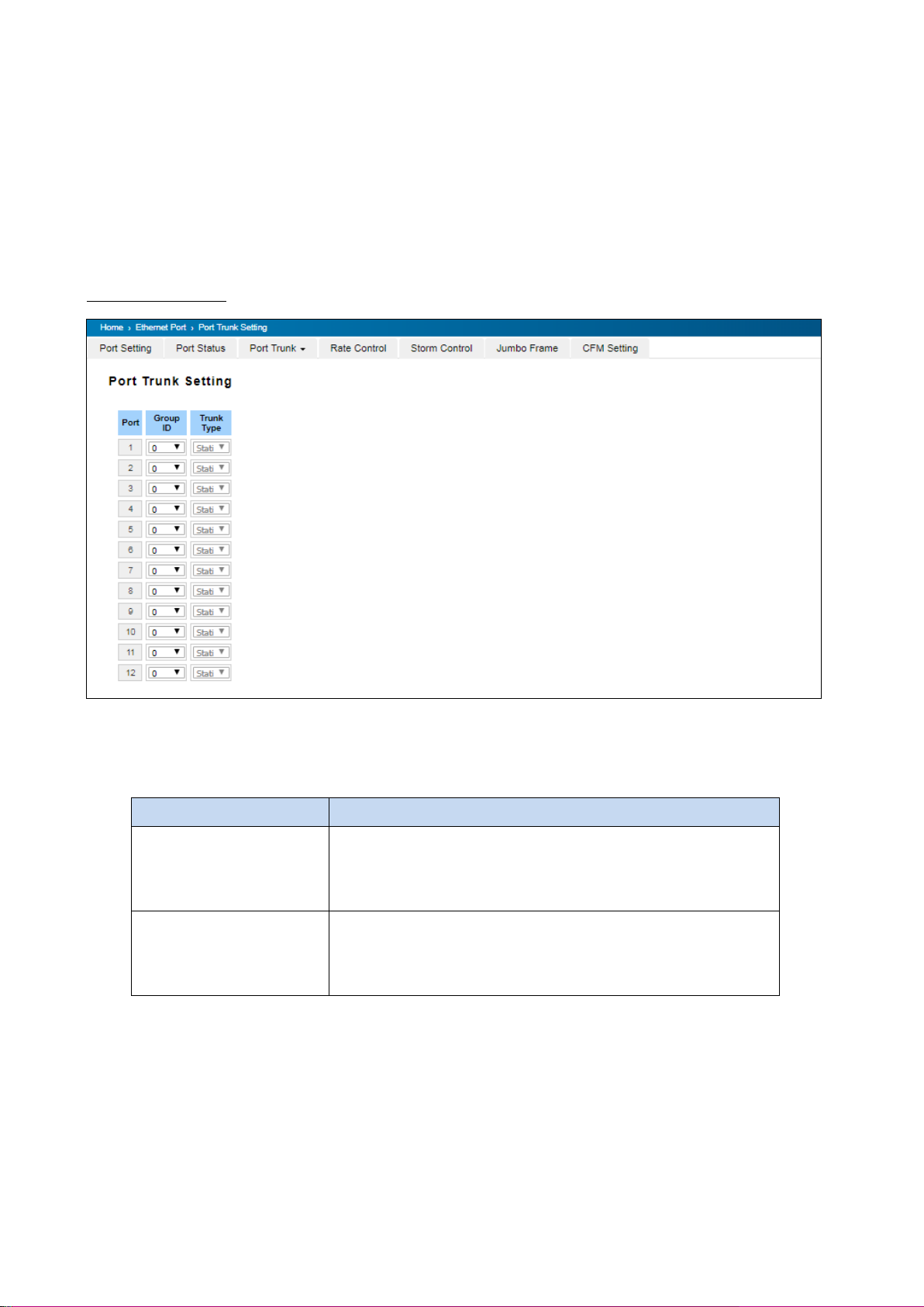
Port Trunk Setting
The switch can support up to 8 trunk groups with 2 trunk members. Since the member ports should use same
speed/duplex, max trunk members would be 8 for 100Mbps, and 2 members for Gigabit.
The description of the columns is as below:
Click on Submit to apply the configuration, and Reload to refresh the table.
35
Page 36
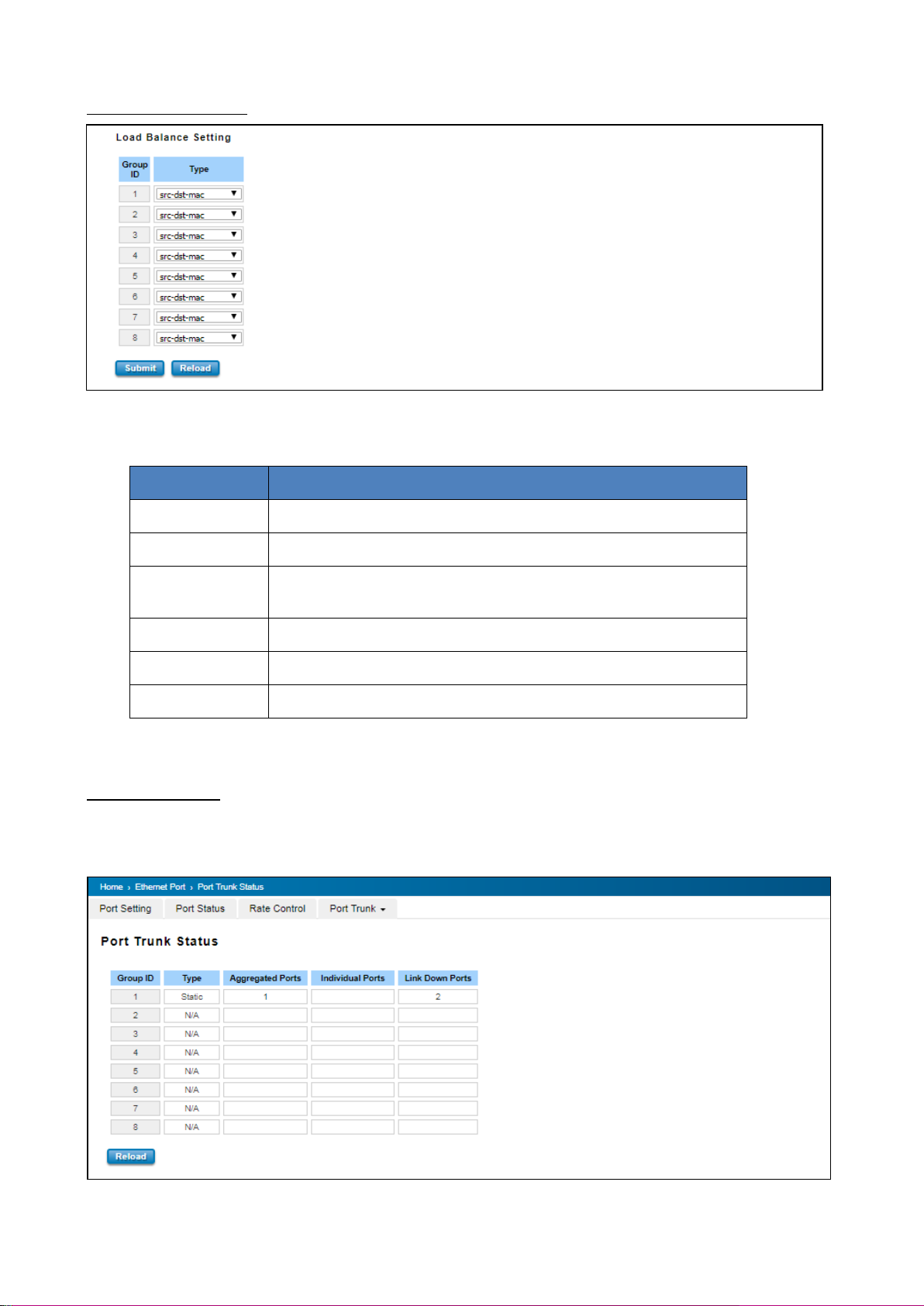
Type
Description
src-mac
load distribution is based on the source MAC address
dst-mac
load distribution is based on the destination-MAC address
src-dst-mac
load distribution is based on the source and destination MAC
address
src-ip
load distribution is based on the source IP address
dst-ip
load distribution is based on the destination IP address
src-dst-ip
load distribution is based on the source and destination IP address
Load Balance Setting
Load Balance Type: Each Trunk Group can support several Load Balance types that can be seen from the table
below:
Click Submit to apply your settings.
Port Trunk Status
This page shows the status of port aggregation. Once the aggregation ports are negotiated well, User will see
following status. The figure below is the Port Trunk Status interface.
36
Page 37
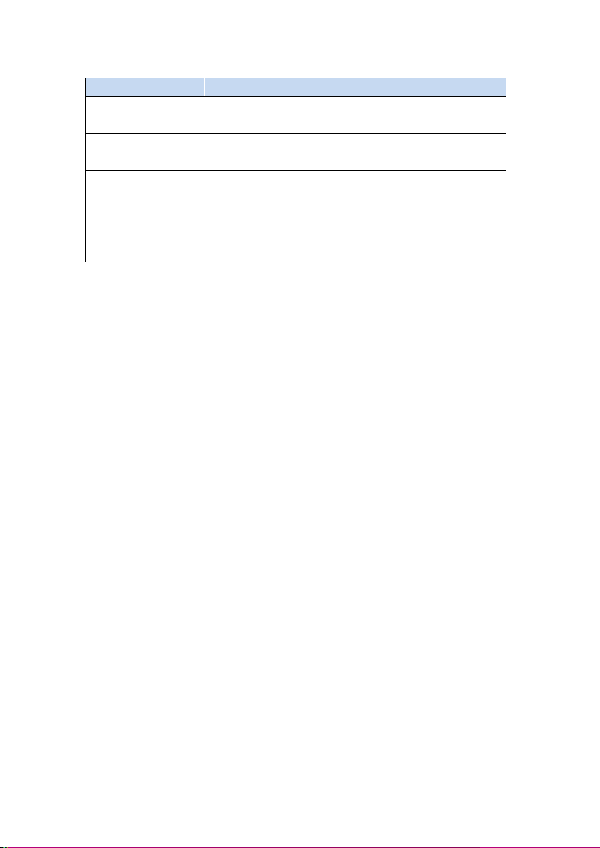
TERMS
DESCRIPTION
Group ID
Display Trunk 1 to Trunk 5 setup in Aggregation Setting.
Type
Static or LACP setup in Aggregation Setting.
Aggregated Ports
When LACP links well, User can see the member ports in aggregated
column.
Individual Ports
When LACP is enabled, member ports of LACP group which are not
connected to correct LACP member ports will be displayed in the
Individual column.
Link Down
When LACP is enabled, member ports of LACP group which are not
linked up will be displayed in the Link Down column.
The description of the columns is as below:
To refresh the list, click Reload.
37
Page 38
TERMS
DESCRIPTION
Packet Type
Select the packet type that wanted to filter.
Ingress
The packet types of the Ingress Rule listed here include
Broadcast Only / Broadcast and multicast / Broadcast,
Multicast and Unknown Unicast or All.
Egress
The packet types of the Egress Rule (outgoing) only support all
packet types.
Rate (Ingress & Egress)
Default value Ingress: 8 Mbps
Default value Egress: 0 Mbps (0 stands for disabling the rate
control for the port.)
Valid values are from 1Mbps-100Mbps for fast Ethernet ports
and gigabit Ethernet ports. The step of the rate is 1 Mbps.
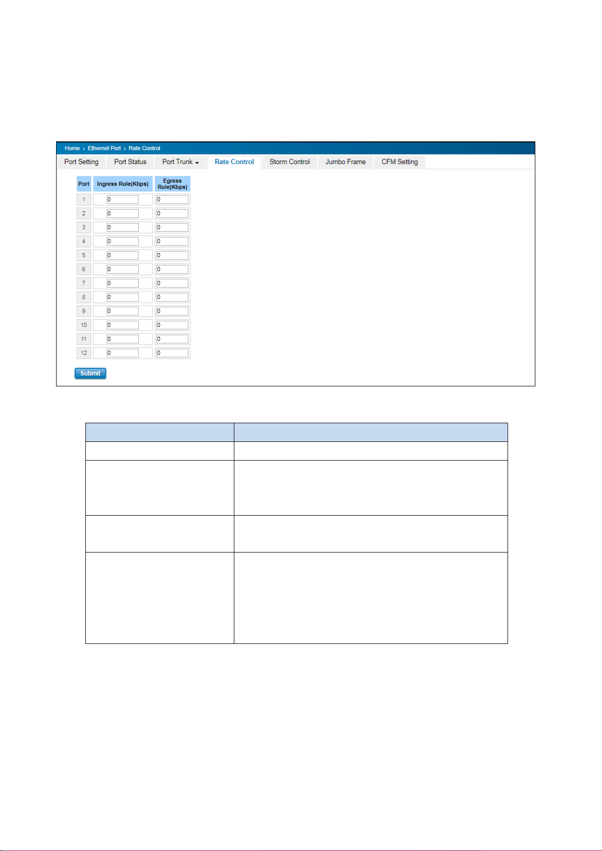
3.2.4 RATE CONTROL
Rate control is a form of flow control used to enforce a strict bandwidth limit at a port. User can program separate
transmit (Egress Rule) and receive (Ingress Rule) rate limits at each port, and even apply the limit to certain packet
types.
The description of the columns is as below:
Click on Submit to apply the configuration.
38
Page 39
TERMS
DESCRIPTION
Broadcast
Default: Disable
Set enable to control Broadcast Packets
DLF
Default: Disable
Set enable to control Destination Lookup Failure packets
Multicast
Default: Disable
Set enable to control Multicast Packets
Rate(Packet/Sec)
Rate limit value 0~262142 packet/sec
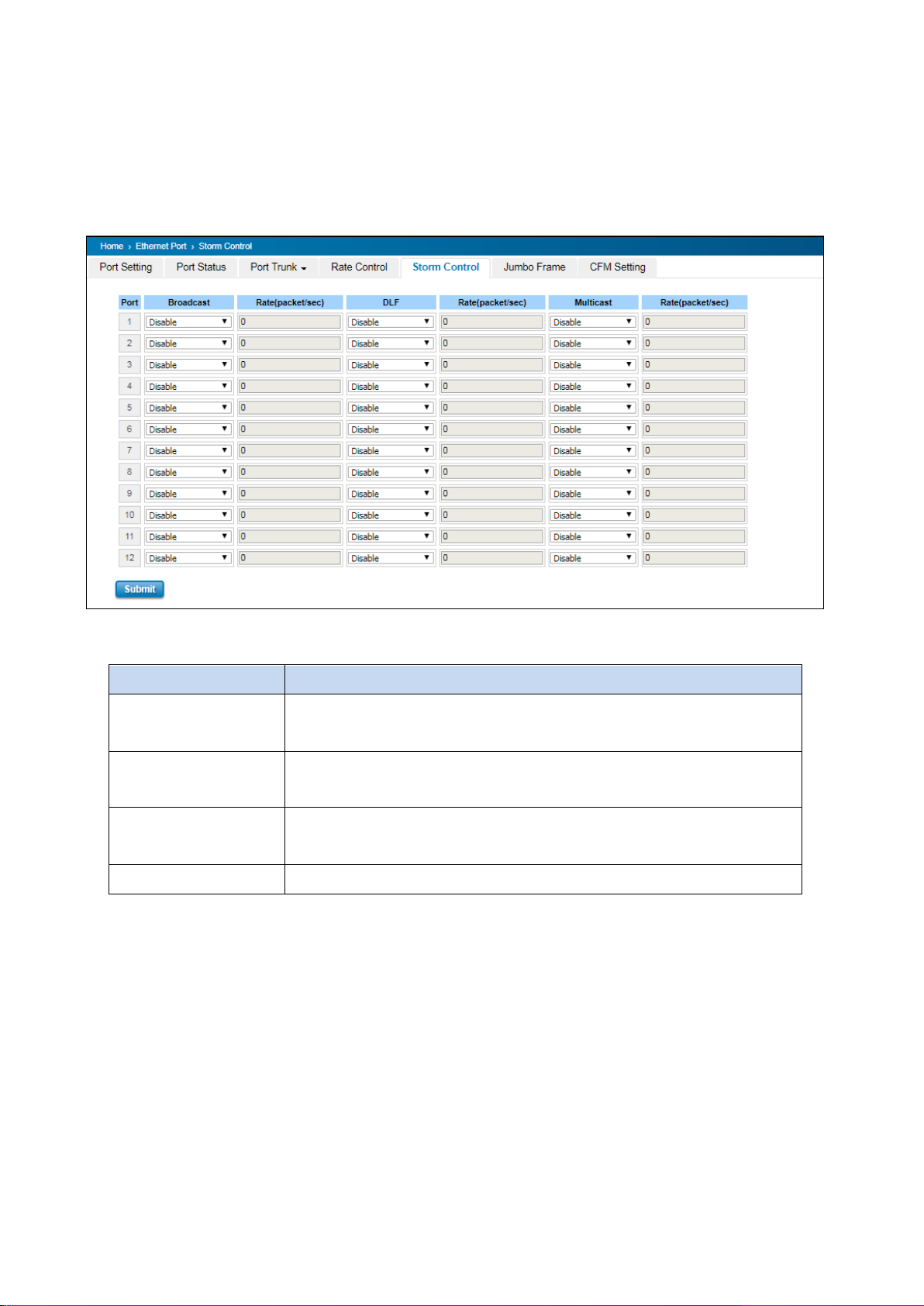
3.2.5 STORM CONTROL
A LAN storm appears when packets flood the LAN, creating excessive traffic and degrading network performance.
Errors in the implementation, mistakes in network configuration, or users issuing a denial-of-service attack can cause
a storm. Storm control prevents traffic on a LAN from being disrupted by a broadcast, DLF, or multicast storm on a
port. In this page, user can configure the storm control for each port.
Click Submit to apply the configuration.
39
Page 40
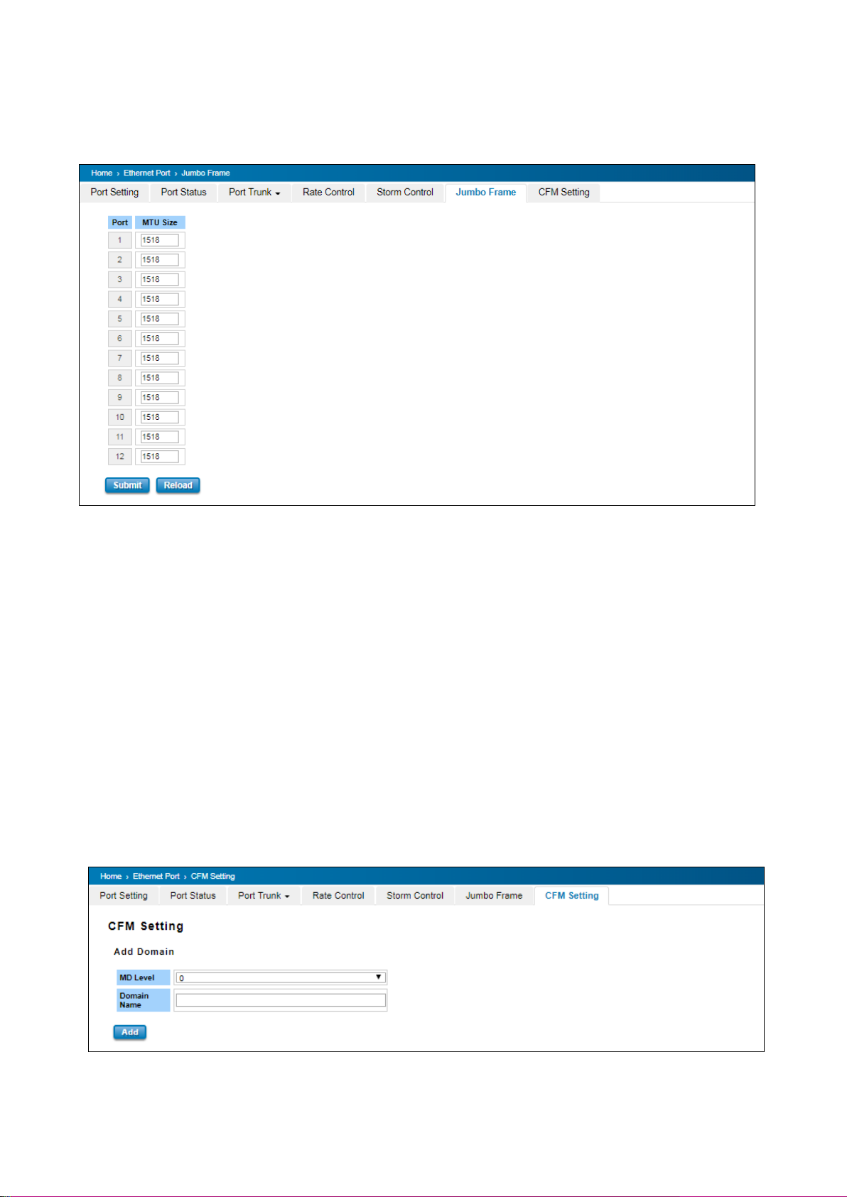
3.2.6 JUMBO FRAME
The switch allows user to configure the size of the Maximum Transmission Unit. The default value is 1,518bytes. The
maximum Jumbo Frame size is 9,216 bytes.
3.2.7 CFM SETTING
Ethernet Connectivity Fault Management (CFM, IEEE 802.1ag) is an end-to-end Ethernet OAM that can cross multiple
domains to monitor the health of the entire service instance. A service instance can be a native Ethernet
VLAN. CFM is a connectivity checking mechanism that uses its own Ethernet frames (its Ethertype is 0x8902 and it
has its own MAC address) to validate the health of the service instance.
Continuity Check Protocol (CCP): "Heartbeating" messages for CFM. The Continuity Check Message (CCM) provides a
means to detect connectivity failures in an MA. CCMs are multicast messages. CCMs are confined to a domain (MD).
These messages are unidirectional and do not solicit a response. Each MEP transmits a periodic multicast Continuity
Check Message inward towards the other MEPs. DP612/DS612 support Hardware CCM transition. The
transition/receiving interval can up to 3.3ms to support detection Gigabit Ethernet cooper interface in 10ms.
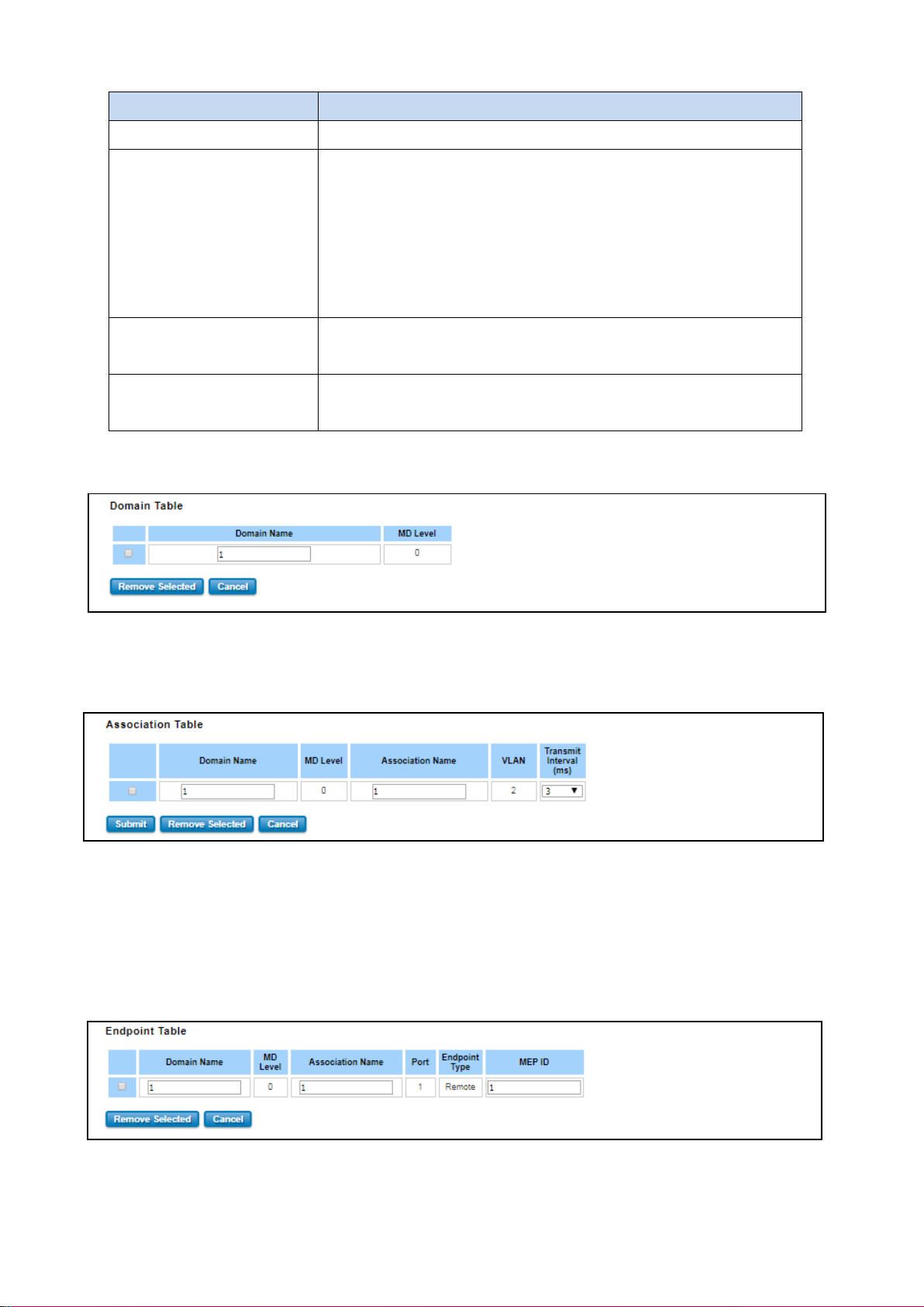
Below is the CFM CCP configuration page. In this page user may configure the Maintenance Domain, Maintenance
Association and the Maintenance association End Point setting.
Add Domain
Add the Domain name and the MD level then click Add.
40
Page 41

TERMS
DESCRIPTION
MD Level
Select the MD Level from 0~7
The eight levels range from 0 to 7. A hierarchical relationship exists between
domains based on levels. The larger the domain, the higher the level value.
Recommended values of levels are as follows:
Customer Domain: Largest (e.g., 7)
Provider Domain: In between (e.g., 3)
Operator Domain: Smallest (e.g., 1)
Domain Name
Enter a new Domain Name. Domain name, maximum of 43 characters
TERMS
DESCRIPTION
Domain Name
Choose the Domain Name that has been added
Association Name
Enter the Association Name. Association name, maximum of 45 characters
VLAN
Choose VLAN that has been assigned
Domain Name
Enter a new Domain Name. Domain name, maximum of 43 characters
Add Association
Choose the Domain Name from the list that has been added up then add a new Association Name for the
Maintenance Association. After that choose the VLAN, Please create VLAN first, and each port set to be “tagged”
Add the Domain association name, end point type, port number and and the MEP ID then click Add.
Add Endpoint
Points at the edge of the domain, define the boundary for the domain. A MEP sends and receives CFM frames
through the relay function, drops all CFM frames of its level or lower that come from the wire side.
All of the configuration above will directly appear at the three table below, Domain Table, Association Table and the
Endpoint Table.
41
Page 42
TERMS
DESCRIPTION
Domain Association Name
Choose the Domain Association Name that has been added
Endpoint Type
Default: Local Endpoint
Choose between Local Endpoint and Remote Endpoint
Local Endpoint: Set the port as the Continuity Check Message (CCM)
sender.
Remote Endpoint: Set the port as the Continuity Check Message (CCM)
receiver.
Port
Default: Port 1
Choose port that need to be assigned
MEP ID
Default: 1
Choose the MEP ID. One MEP refer to one MEP ID
Domain Table
This section shows the Domain entry. User may delete the list, by select the list and click Remove Selected
Association Table
This section shows the Association entry. In this table, user can configure the Configure Continuity Check Message
transmit interval (default 3 ms), and after that click Submit to apply the setting. User may delete the list, by select the
list and click Remove Selected
Endpoint Table
This section shows the Endpoint entry. User may delete the list, by select the list and click Remove Selected
42
Page 43
3.3 POWER OVER ETHERNET (PoE MODELS ONLY)
Power over Ethernet has become increasingly popular due in large part to the reliability provided by PoE Ethernet
switches that supply the necessary power to Powered Devices (PD) when AC power is not readily available or
cost-prohibitive to provide locally. WoMaster’ industrial DIN Rail PoE Switch compliant with IEEE 802.3af and IEEE
802.3at. All of WoMaster’ switches adapt 8-Port PoE injectors in port 1 to port 8, each port with the ability to deliver
30W to compatible IEEE 802.3at standard and provides 240W power budget for hall system.
Power over Ethernet can be used with:
• Surveillance cameras
• Security I/O sensors
• Industrial wireless access points
• Emergency IP phones
3.3.1 PoE STATUS
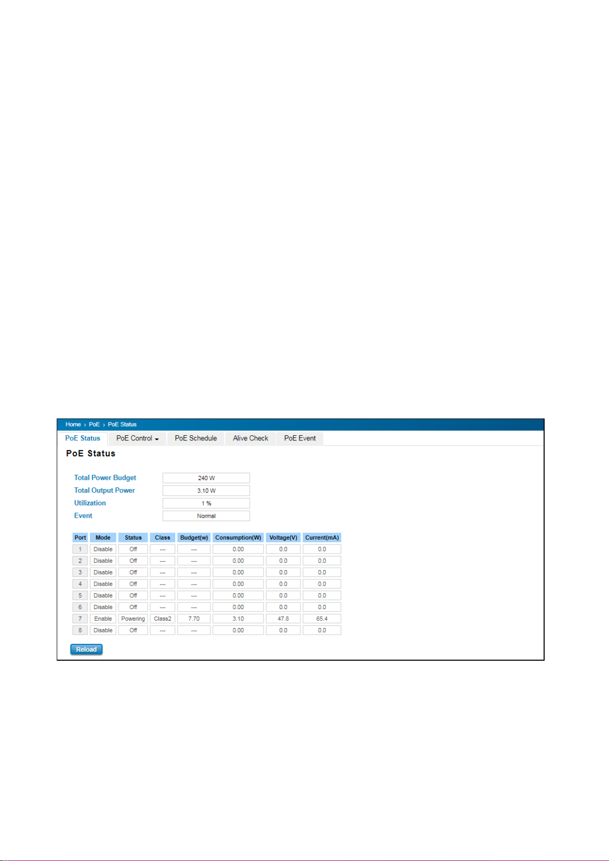
The PoE Status page shows the system PoE status and the operating status of each PoE Port. The information
includes PoE mode, Operation status, and PD class, Power Consumption, Voltage and Current. For example, in the
figure below, Port 7 was enabled and is supplying power to a Class 2 Powered Device (PD) indicated under the
Classification column. The PD device is rated at 47.8V and 65.4mA. The total power consumption for this PD is 3.10W
with Budget 7.70W. To check the status of the PoE port, please click on the Reload button.
43
Page 44
TERMS
DESCRIPTION
Mode
Enable/Disable/Schedule Indicates the PoE port status
Status
Default: Off
PoE status is included Off, Powering, and Searching.
Off – PoE is inactive.
Powering – PoE is enabled and powering the PD.
Searching – Searching the PD which need the power.
Class
Indicates the PD included in which PoE class.
Consumption (W)
Indicates the actual Power consumed value for PoE port
Voltage (V)
Indicates the actual Voltage consumed value for PoE port
Current (mA)
Indicates the actual Current consumed value for PoE port
TERMS
DESCRIPTION
PoE System
Enable or disable system’s PoE function.
Budget (W)
Default: 240W
The power supply maximum output budget.
The description of the columns is as below:
3.3.2 PoE CONTROL
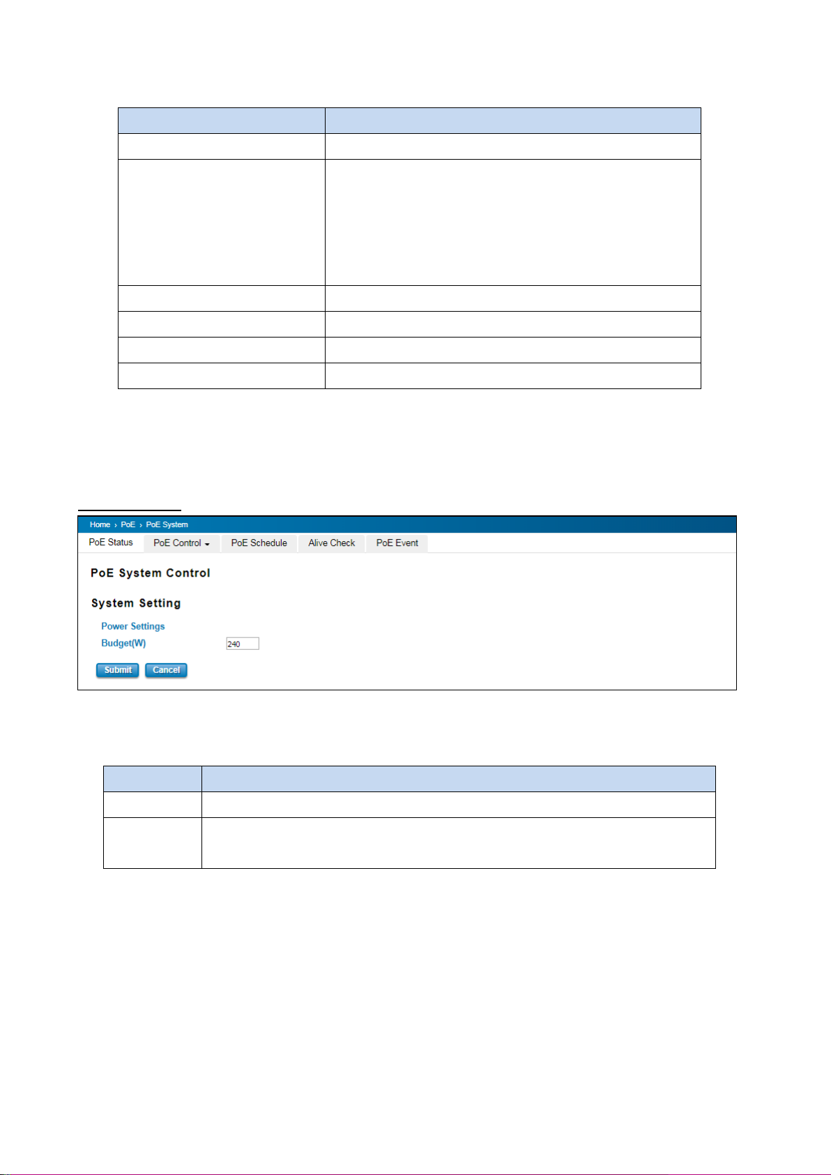
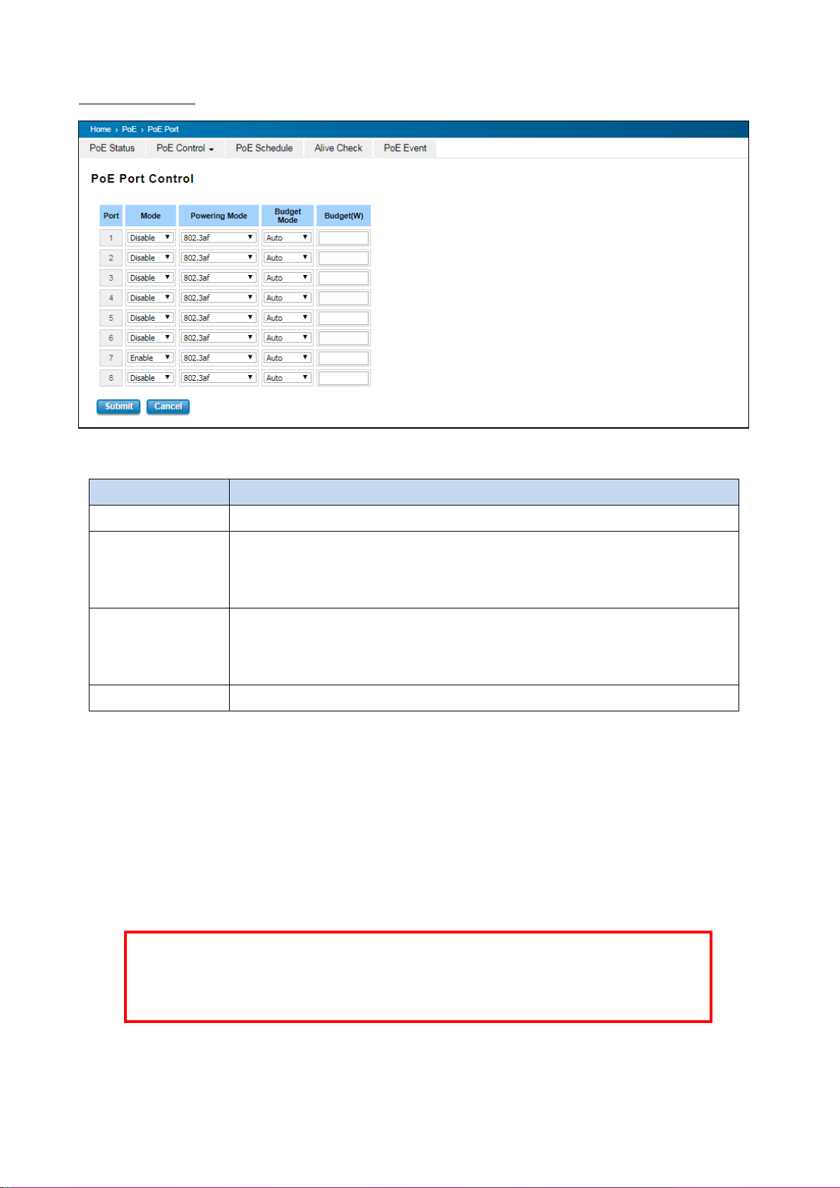
The PoE control includes 3 parts, System Setting, Port setting and PD status detection. The following section will
introduce the function.
System Setting
The figure above is System Setting interface. In this section, user can enable or disable the PoE function.
The description of the columns is as below:
After finished configuring the settings, click on Submit to save the configuration.
44
Page 45
TERMS
DESCRIPTION
Mode
Enable/Disable/Schedule port’s PoE function.
Powering Mode
802.3af, 802.3at (LLDP), 802.3at (2-event) and forced mode.
*Forced mode will ignore the classification behaviors and apply power onto the
RJ-45, uses the forced mode must be carefully.
Budget Mode
Choose budget mode as auto or manual. If auto the budget would be delivered
automatically based on the end device requirement. If user choose manual, user can
input the number at the budget text box.
Budget (W)
Input the budget.
WARNING: During the PoE operating, the surface will accumulate heat and caused surface
temperature becomes higher than ambient temperature. Do remember don’t touch device
surface during PoE operating.
PoE Port Control
The description of the columns is as below:
If the system PoE consumption is over the system budget control, the PoE system will turn off low priority port PoE
function, until the consumption is becomes smaller than the system budget. After finished configuring the settings,
click on Submit to save the configuration.
To enable the IEEE 802.3at High Power PoE function, the power input voltage should be DC 50 ~57V to obtain better
performance. Applies DC 48V to PoE Switch and perform 30W high power output may cause the PoE disable
automatically. To avoid this issue, we suggest adjust the power supply output to 50V DC or higher. In usually, the
Switching power supply adopted adjust resistor for voltage fine tune.
45
Page 46
3.3.3 PoE SCHEDULING
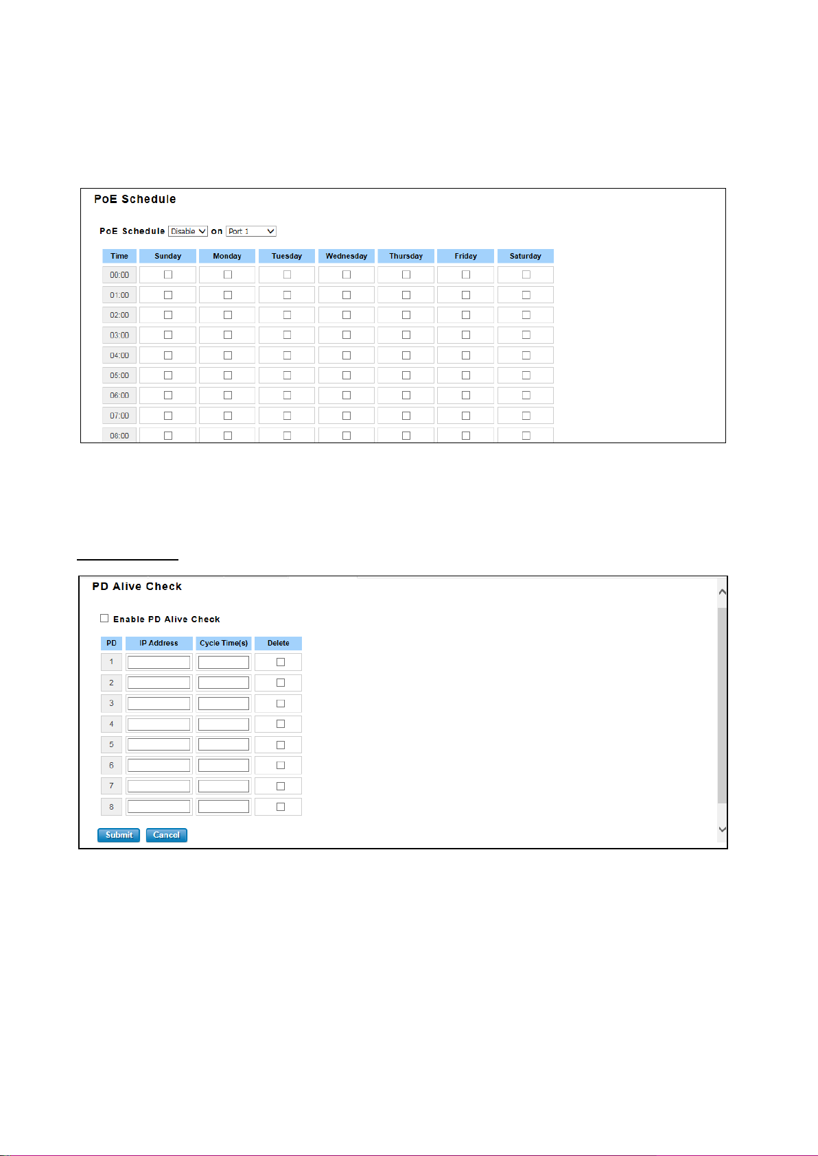
For energy saving or power recycle powered devices, the PoE managed switch’s PoE scheduling interface allows users
to appoint any date and time to enable or disable PoE functions for each PoE port. User need to configure PoE
Scheduling and select a target port manually to enable this function. The figure below is PoE Schedule interface.
The PoE schedule supports hourly and weekly base PoE schedule configuration. Enable and select the target port
and marking the time frame, then click Submit to activate the PoE scheduling function on selected port.
3.3.4 ALIVE CHECK
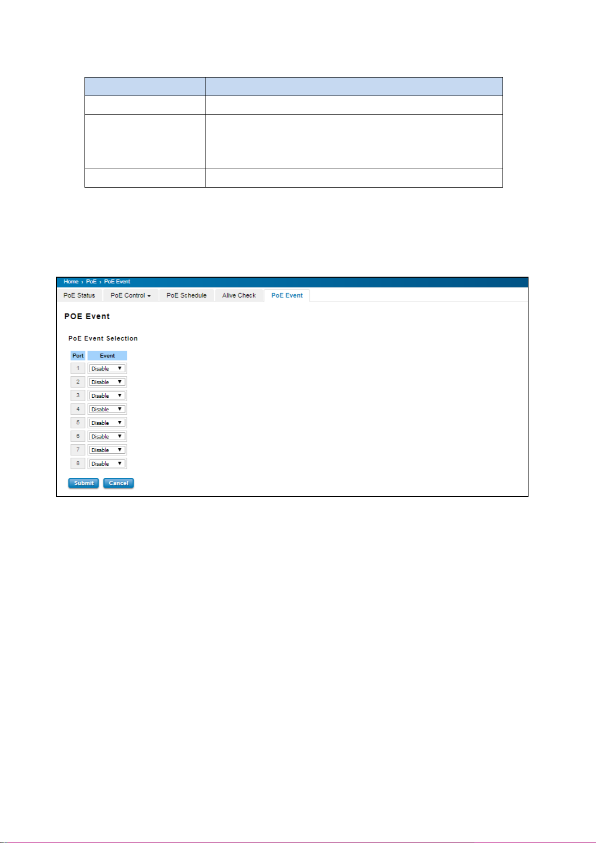
PD Alive Check
WoMaster’ Switches support a useful function that help user to maintain the PD’s status and help use to saving the
maintenance time and money. Once user defined this function, the PoE Switch will request PD system and turn-off
PoE power if PD system does not echo the request. After the duration time (cycle time), the PoE switch will start
request PD again.
46
Page 47
TERMS
DESCRIPTION
IP address
PD’s IP-address that installed on the port.
Cycle time
User measured the PD system boots duration time.
*Most of PD system – IP camera will take at least 40~50 seconds.
Here, we suggest that user sets the cycle time to 90 seconds.
Delete
Delete PD’s IP-address that has been selected.
The description of the columns is as below:
After finished configuring the settings, click on Submit to save the configuration.
3.3.5 PoE EVENT
In this section, user is allowed to configure the PoE Event, the value is Enable and Disable. When the status is
enabled PoE itself will detect the PD, then it will deliver the power when the PD is detected.
47
Page 48
3.4 REDUNDANCY
Redundancy role on the network is to help protect critical links against failure, protects against network loops, and
keeps network downtime at a minimum. Sustainable, uninterrupted data communication network is critical for
industrial applications. Network Redundancy allows user to set up redundant loops in the network to provide a
backup data transmission route in the event that a cable is inadvertently disconnected or damaged. This switch
supports Rapid Spanning Tree Protocol (RSTP)/Multiple Spanning Tree Protocol (MSTP) and ITU-T G.8032 v1/v2
Ethernet Ring Protection Switching (ERPS). ERPS (Ethernet Ring Protection Switching) or ITU-T G.8032 is a loop
resolution protocol, just like STP. Convergence time is much quicker in ERPS. Unlike in STP, most of the ERPS
parameters are management configured – which link to block in the start etc. Normally ERPS is implemented with-in
the same administrator domain, there by having control on the nodes participating in the Ring. This technology
provides sub-50ms protection and recovery switching for Ethernet traffic. This is a particularly important feature for
industrial applications, since it could take several minutes to locate the disconnected or severed cable.
3.4.1 RSTP SETTINGS
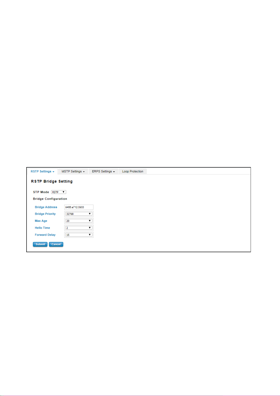
This page allows select the RSTP mode and configuring the global RSTP Bridge Configuration.
The STP mode includes the STP, RSTP, MSTP and Disable. User can select the STP mode for user system first. The
default mode is RSTP enabled. After user selects the STP or RSTP mode; user should continue to configure the global
Bridge parameters for STP and RSTP. If user selects the MSTP mode, user need go to MSTP Configuration page.
Spanning Tree Protocol (STP)
STP is a Layer 2 link management protocol that provides path redundancy while preventing loops in the network. For
a Layer 2 Ethernet network to function properly, only one active path can exist between any two stations.
Spanning-tree operation is transparent to end stations, which cannot detect whether they are connected to a single
LAN segment or a switched LAN of multiple segments.
Rapid Spanning Tree Protocol (RSTP)
If the destination from a switch is more than one path, it will lead to looping condition that can generate broadcast
storms in a network. The spanning tree was created to combat the negative effects of message loops in switched
48
Page 49

NOTE:
1. The bridge priority value must be in multiples of 4096. A device with a lower number has a higher
bridge priority.
2. The Web GUI allows user selects the priority number directly. This is the convenient of the GUI design.
When user configures the value through the CLI or SNMP, user may need to type the value directly.
Please follow the n x 4096 rules for the Bridge Priority.
networks. A spanning tree algorithm is used to automatically sense whether a switch has more than one way to
communicate with a node. It will then select the best path, and block the other path. Spanning Tree Protocol (STP)
introduced a standard method to accomplish this. Rapid Spanning Tree Protocol (RSTP) was adopted and represents
the evolution of STP, providing much faster spanning tree convergence after a topology change.
MSTP (Multiple Spanning Tree Protocol)
MSTP is a direct extension of RSTP that can provide an independent spanning tree for different VLANs. It simplifies
network management by limiting the size of each region, and prevents VLAN members from being segmented from
the group. MSTP can provide multiple forwarding paths and enable load balancing. By understand the architecture,
allow you effectively maintain and operate the correct spanning tree. One VLAN can be mapped to an instance. The
maximum Instance of the switch is 16, with the range is from 0-15. The MSTP builds a separate Multiple Spanning
Tree (MST) for each instance to maintain connectivity among each of the assigned VLAN groups. An Internal Spanning
Tree (IST) is used to connect all the MSTP switches within an MST region. An MST Region may contain multiple MSTP
Instances.
MSTP connects all bridges and LAN segments with a single Common and Internal Spanning Tree that is formed as a
result of the running spanning tree algorithm between switches that support the STP, RSTP, MSTP protocols.
To configure the MSTP setting, the STP Mode of the RSTP Settings page should be changed to MSTP mode first. After
enabled MSTP mode, user can go to the MSTP Settings page.
Bridge Configuration
Bridge Address: This shows the switch’s MAC address.
Priority (0-61440): RSTP uses bridge ID to determine the root bridge, the bridge with the highest bridge ID becomes
the root bridge. The bridge ID is composed of bridge priority and bridge MAC address. So that the bridge with the
highest priority becomes the highest bridge ID. If all the bridge ID has the same priority, the bridge with the lowest
MAC address will then become the root bridge.
Max Age (6-40): Enter a value from 6 to 40 seconds here. This value represents the time that a bridge will wait
without receiving Spanning Tree Protocol configuration messages before attempting to reconfigure.
Hello Time (1-10): Enter a value from 1 to 10 seconds here. This is a periodic timer that drives the switch to send out
BPDU (Bridge Protocol Data Unit) packet to check current STP status. The root bridge of the spanning tree topology
periodically sends out a hello message to other devices on the network to check if the topology is normal. The hello
time is the amount of time the root has waited during sending hello messages.
Forward Delay Time (4-30): Enter a value between 4 and 30 seconds. This value is the time that a port waits before
changing from Spanning Tree Protocol learning and listening states to forwarding state.
49
Page 50
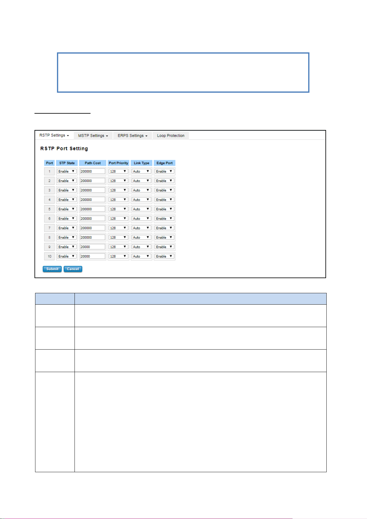
TERMS
DESCRIPTION
STP State
Default: Enable
To enable or disable STP function.
Path Cost
Enter a number between 1 and 200,000,000. This value represents the “cost” of the path to the
other bridge from the transmitting bridge at the specified port.
Priority
Enter a value between 0 and 240, using multiples of 16. This is the value that decides which port
should be blocked by priority in a LAN.
Link Type
There are 3 types for user selects Auto, P2P and Share. Some of the rapid state transitions that
are possible within RSTP depend upon whether the port of concern can only be connected to
another bridge (i.e. it is served by a point-to-point LAN segment), or if it can be connected to two
or more bridges (i.e. it is served by a shared-medium LAN segment). This function allows link
status of the link to be manipulated administratively. Auto - means to auto select P2P or Share
mode.
P2P - means P2P is enabled; the 2 ends work in full duplex mode.
Share - means P2P is disabled; the 2 ends may connect through a share media and work in half
duplex mode.
NOTE: User must follow the rule to configure Hello Time, Forwarding Delay, and Max Age
parameters.
2× (Forward Delay Time – 1 sec) ≥ Max Age Time ≥ 2 × (Hello Time value + 1 sec)
Once user has completed user configuration, click on Submit to apply user settings.
RSTP Port Settings
Select the port user wants to configure and user will be able to view current setting and status of the port.
The description of the columns is as below:
50
Page 51
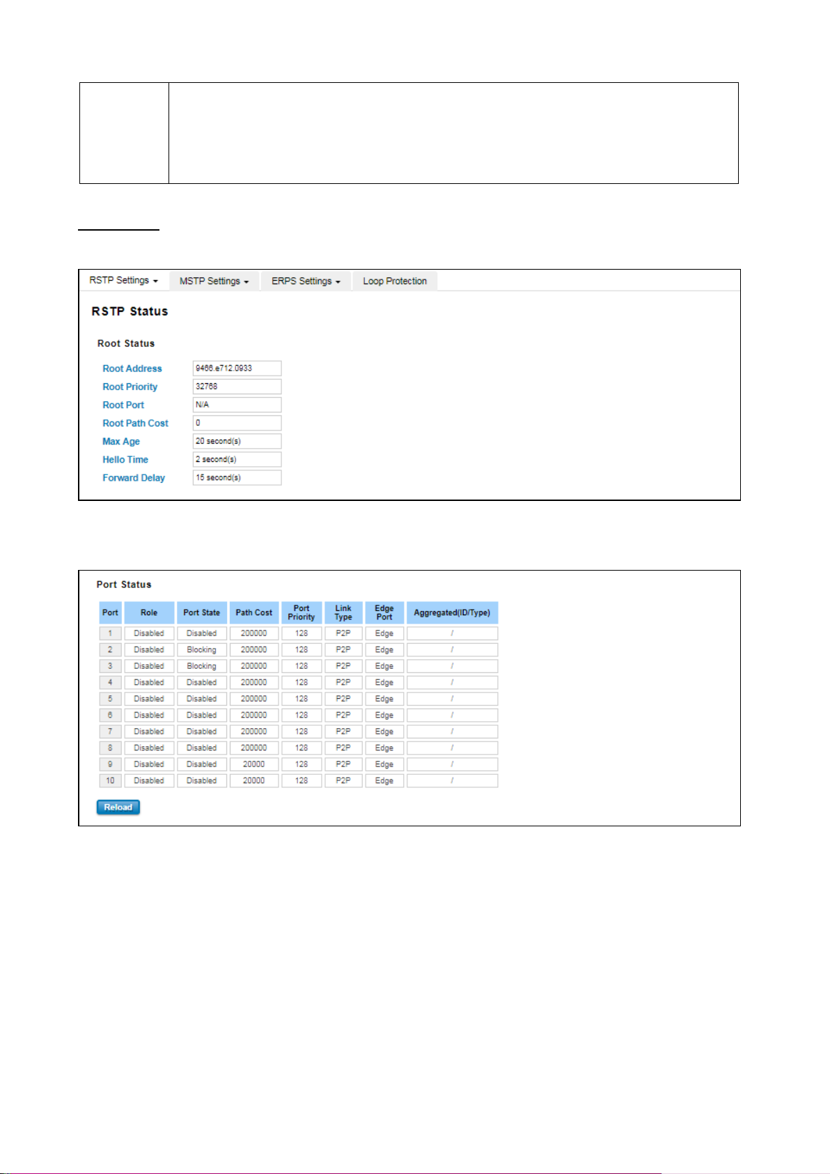
Edge Port
A port directly connected to the end stations cannot create a bridging loop in the network. To
configure this port as an edge port, set the port to the Enable state. When the non-bridge device
connects an admin edge port, this port will be in blocking state and turn to forwarding state in 4
seconds.
Once user finished user configuration, click on Submit to save user settings.
RSTP Status
This page allows user to see the information of the root switch and port status.
Root Status: User can see root Bridge ID, Root Priority, Root Port, Root Path Cost and the Max Age, Hello Time and
Forward Delay of BPDU sent from the root switch.
Port Status: User can see port Role, Port State, Path Cost, Port Priority, Oper P2P mode, Oper edge port mode and
Aggregated (ID/Type).
51
Page 52
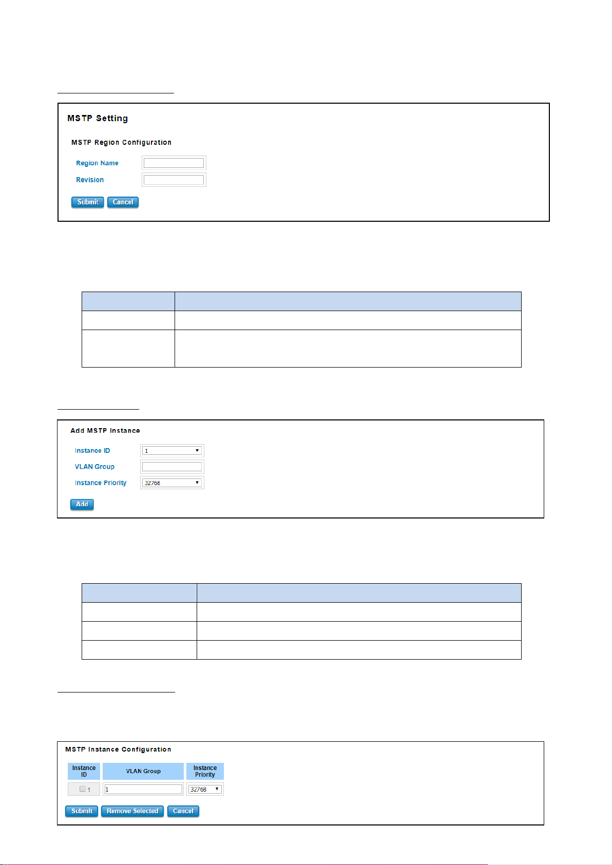
TERMS
DESCRIPTION
Region Name
The name for the Region. Maximum length: 32 characters.
Revision
Default: 0
The revision for the Region. Range: 0-65535
TERMS
DESCRIPTION
Instance ID
Select the Instance ID, the available number is 1-15.
VLAN Group
Type the VLAN ID that user wants mapping to the instance.
Instance Priority
Assign the priority to the instance. (0-61440)
3.4.2 MSTP SETTINGS
MSTP Region Configuration
This page allows configure the Region Name and its Revision, mapping the VLAN to Instance and check current MST
Instance configuration. The network can be divided virtually to different Regions. The switches within the Region
should have the same Region and Revision level.
Once user finished user configuration, click on Submit to apply user settings.
Add MSTP Instance
This page allows mapping the VLAN to Instance and assign priority to the instance. Before mapping VLAN to Instance,
user should create VLAN and assign the member ports first. Please refer to the VLAN setting page. After finish the
configuration, click on Add to apply user settings.
MST Instance Configuration
This page allows user to see the current MST Instance Configuration user added. Click on Submit to apply the setting.
User can Remove the instance in this page.
52
Page 53
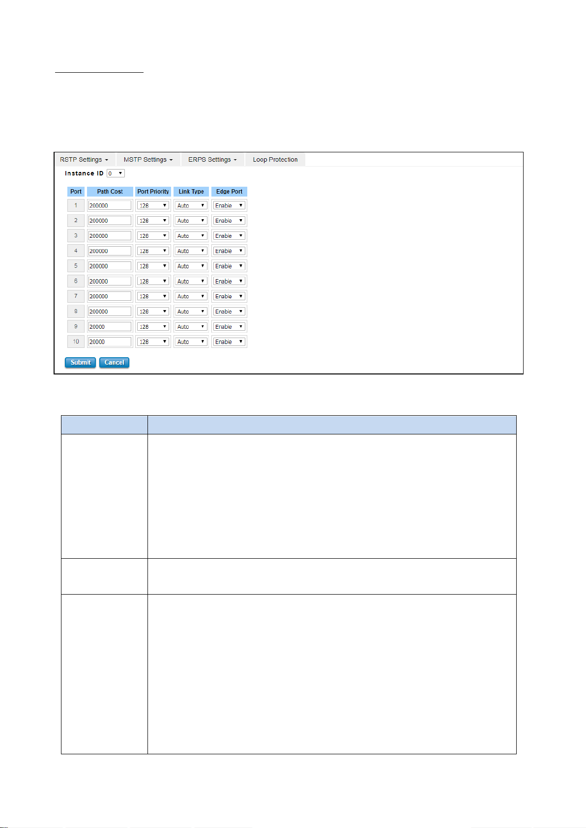
TERMS
DESCRIPTION
Path Cost
Enter a number between 1 and 200,000,000. This value represents the cost of the path to
the other bridge from the transmitting bridge at the specified port. Path cost value is
derived from the media speed of an interface. If a loop occurs, the MSTP uses cost when
selecting an interface to put in the forwarding state. Lower cost values can be assigned to
interfaces that selected first and higher cost values that selected last. If all interfaces
have the same cost value, the MSTP puts the interface with the lowest interface number
in the forwarding state and blocks the other interfaces.
Port Priority
Enter a value between 0 and 240. This is the value that decides which port should be
blocked by priority in a LAN.
Link Type
There are 3 types for user selects Auto, P2P and Share. Some of the rapid state
transitions that are possible within RSTP depend upon whether the port of concern can
only be connected to another bridge (i.e. it is served by a point-to-point LAN segment), or
if it can be connected to two or more bridges (i.e. it is served by a shared-medium LAN
segment). This function allows link status of the link to be manipulated administratively.
Auto - means to auto select P2P or Share mode.
P2P - means P2P is enabled; the 2 ends work in full duplex mode.
Share - means P2P is disabled; the 2 ends may connect through a share media and work
in half duplex mode.
MSTP Port Setting
This page allows configure the Port settings. Choose the Instance ID user wants to configure. The MSTP enabled and
linked up ports within the instance will be listed in this table. Note that the ports not belonged to the Instance, or
the ports not MSTP activated will not display. The meaning of the Path Cost, Priority, Link Type and Edge Port is the
same as the definition of RSTP.
The description of the columns is as below:
53
Page 54
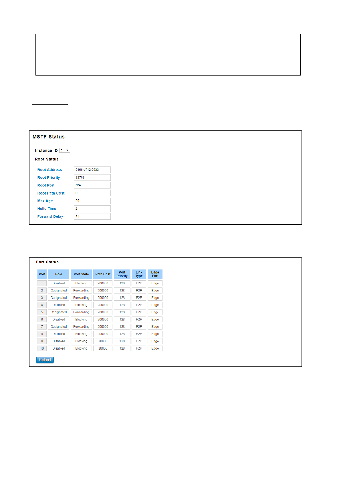
Edge Port
A port directly connected to the end stations cannot create a bridging loop in the
network. To configure this port as an edge port, set the port to the Enable state. When
the non-bridge device connects an admin edge port, this port will be in blocking state and
turn to forwarding state in 4 seconds.
Once user finished user configuration, click on Submit to save user settings.
MSTP Status
This page allows user to see the current MSTP status. Choose the Instance ID first. If the instance is not added, the
information remains blank. The Root Information shows the setting of the Root switch.
Root Status: User can see Root Address, Root Priority, Root Port, Root Path Cost and the Max Age, Hello Time and
Forward Delay of BPDU sent from the root switch based on the Instance ID.
Port Status: User can see port Role, Port State, Path Cost, Port Priority, Link Type and the Edge Port within the
instance. Click Reload to refresh the information display.
54
Page 55
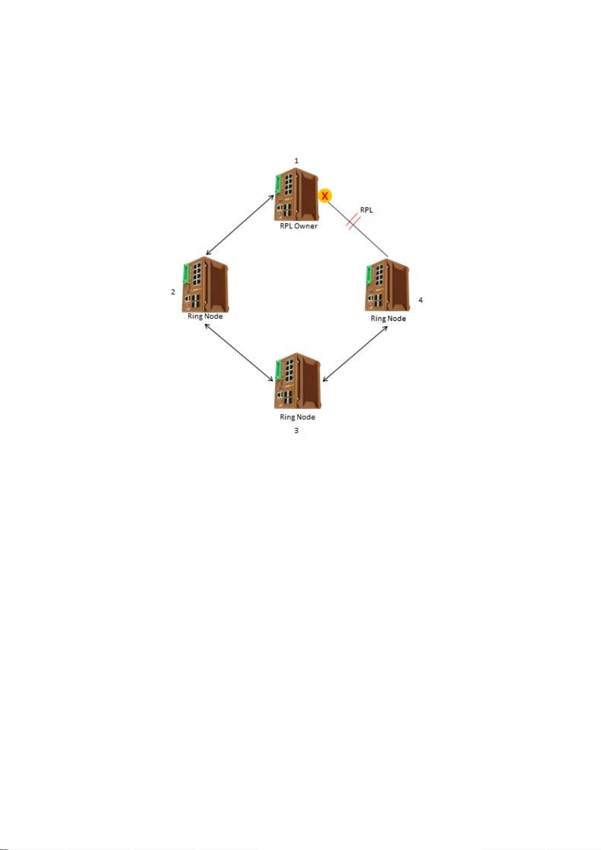
3.4.3 ERPS SETTINGS
Ethernet Ring Protection Switching (ERPS) is a protocol for Ethernet layer network rings. The protocol specifies the
protection mechanism for sub-50ms delay time. The ring topology provides multipoint connectivity economically by
reducing the number of links. ERPS provides highly reliable and stable protection in the ring topology, and it never
forms loops, which can affect network operation and service availability.
The figure above shows that each Ethernet Ring Node is connected to other Ethernet Ring Nodes that participating in
the same Ethernet Ring using two independent links. In the Ethernet ring, loops can be avoided by guaranteeing that
traffic may flow on all but one of the ring links at any time. This particular link is called Ring Protection Link (RPL). A
control message called Ring Automatic Protection Switch (R-APS) coordinates the activities of switching on/off the
RPL. Under normal conditions, this link is blocked by the Owner Node. Thus, loops can be avoided by this mechanism.
In case an Ethernet ring failure occurs, one designated Ethernet Ring Node called the RPL Owner Node will be
responsible for unblocking its end of the RPL to allow RPL to be used as a backup link. The RPL is the backup link
when one link failure occurs.
WoMaster managed switches provide a number of Ethernet ring protocol. The ERPS/Ring section is subdivided into
two menus, which are: ERPS Setting and ERPS Status.
55
Page 56
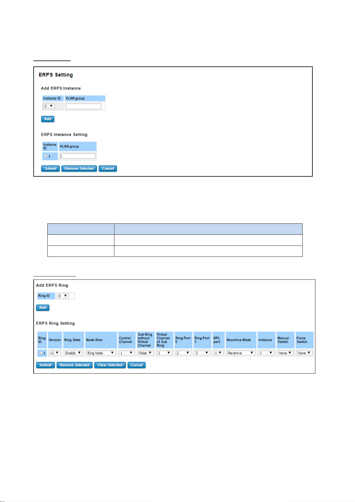
TERMS
DESCRIPTION
Instance ID
Select the Instance ID, the available number is 1-15.
VLAN Group
Type the VLAN ID that user wants mapping to the instance.
3.4.3.1 ERPS SETTINGS
ERPS Setting
Add ERPS Instance is a section for mapping the VLAN to Instance. Before mapping VLAN to Instance, user should
create VLAN and assign the member ports first. Please refer to the VLAN setting page.
After click the Add button, the Instance ID and the VLAN group information will directly display in the ERPS Instance
Setting section.
Add ERPS Ring
Add ERPS Ring is a section to add the Ring ID of the created Protection group; it must be an integer value between 0
and 31. The maximum numbers of ERPS Protection Groups that can be created are 32. Click the ID of a Protection
group to enter the configuration page. After click Add button, one line will be directly created in the ERPS Ring
Setting section. The ERPS Ring Setting section is a table that used to set up the ERPS Ring configuration.
56
Page 57

TERMS
DESCRIPTION
Ring ID
Display the Ring ID
Version
ERPS Protocol Version - v1 or v2.
Ring State
Default: Disable
Enable - Ring Status is enable
Disable - Ring Status is disable
Node Role
It can be either RPL owner or RPL Neighbor or Ring Node.
Control Channel
Default: 1
Control channel is implemented using a VLAN. Each ERP instance uses a
tag-based VLAN for sending and receiving R-APS messages. (1-4094)
Sub Ring without Virtual
Channel
Default: False
True – if doesn’t have a virtual channel
False – if have any virtual channel
Virtual Channel of Sub Ring
Default: 1
Sub-rings can have a virtual channel on the interconnected node. Choose the
number based on the VLANs Range (1-4094)
Ring Port 0
This will create a Port 0 of the switch in the Ring. Choose the port number that
belongs to Ring port 0
Ring Port 1
This will create Port 1 of the switch in the Ring. As interconnected sub-ring will
have only one ring port, "Port 1" is configured as "0" for interconnected
sub-ring. "0" in this field indicates that no "Port 1" is associated with this
instance. Choose the port number that belongs to Ring port 1.
RPL Port
This allows you to select the east port or west port as the RPL block.
Revertive Mode
Default: Revertive
Revertive mode, after the conditions causing a protection switch has cleared;
the traffic channel is restored to the working transport entity that is blocked on
the RPL. In Non-Revertive mode, the traffic channel continues to use the RPL, if
it is not failed, after a protection switch condition has cleared.
Instance
Select the Instance ID, the available number is 1-15.
Manual Switch
Default: None
In the absence of a failure or FS, Manual Switch command forces a block on the
ring port where the command is issued.
Choose 0 or 1, refers to Ring Port 0 or Ring Port 1.
Force Switch
Default: None
Forced Switch command forces a block on the ring port where the command is
issued. Choose 0 or 1, refers to Ring Port 0 or Ring Port 1.
Below is the description table.
57
Page 58
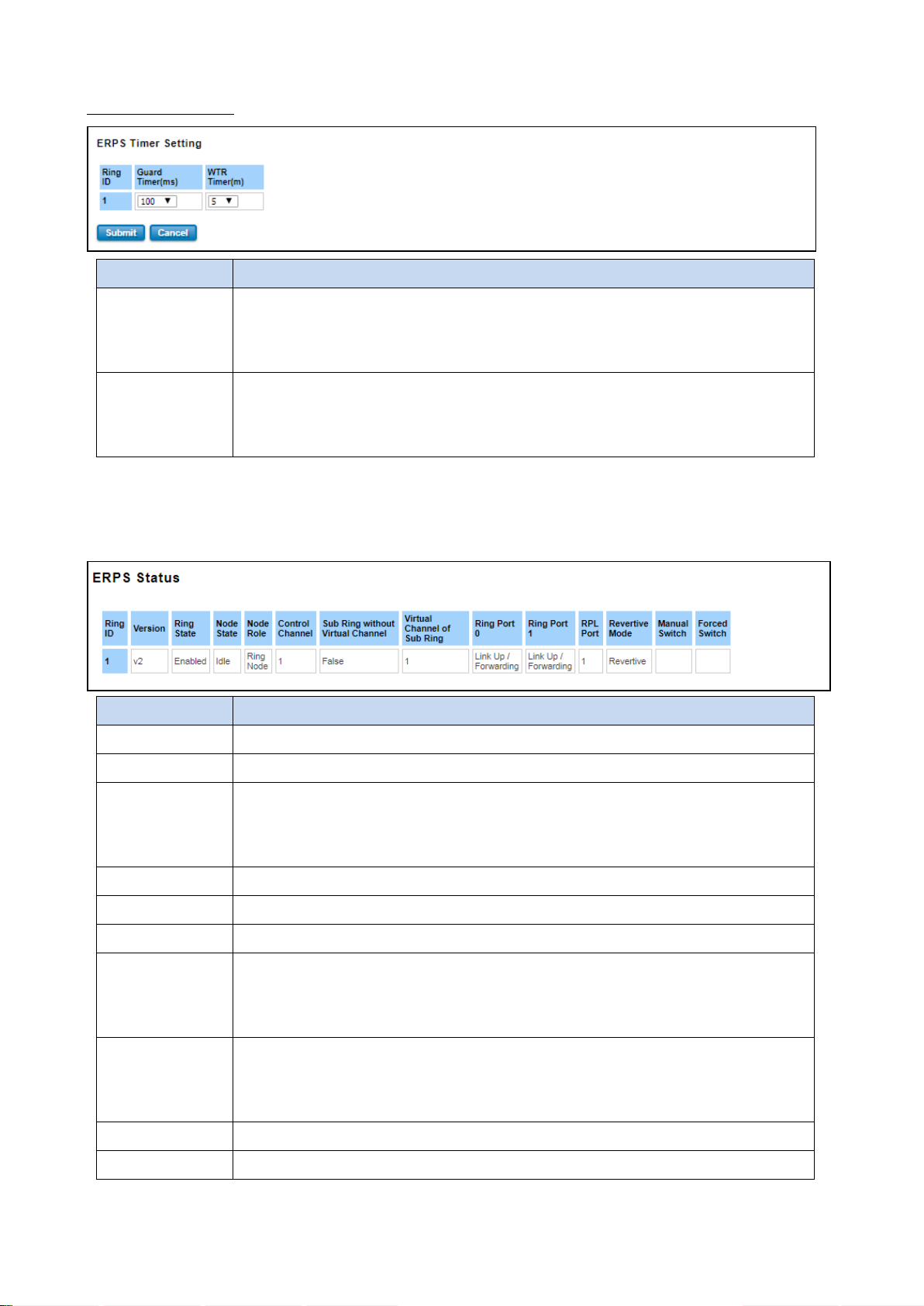
TERMS
DESCRIPTION
Guard Timer (ms)
Guard timeout value to be used to prevent ring nodes from receiving outdated R-APS
messages. The period of the guard timer can be configured in 10 ms steps between 10 ms
and 2000 ms, with a default value of 100 ms.
WTR Timer (m)
The Wait To Restore timing value to be used in revertive switching. The period of the
WTR time can be configured by the operator in 1 minute steps between 5 and 12 minutes
with a default value of 5 minutes.
TERMS
DESCRIPTION
Ring ID
Display the Ring ID
Version
ERPS Protocol Version - v1 or v2.
Ring State
Default: Disable
Enabled - Ring Status is enable
Disabled - Ring Status is disable
Node State
Status from the Ring is Idle, Protection or Pending.
Node Role
It can be either RPL owner or RPL Neighbor or Ring Node.
Control Channel
Control Channel is referred to the VLANs number (1-4094)
Sub Ring without
Virtual Channel
Default: False
True – if have a virtual channel
False – if doesn’t have any virtual channel
Virtual Channel of
Sub Ring
Default: 1
Sub-rings can have a virtual channel on the interconnected node. Choose the number
based on the VLANs Range (1-4094)
Ring Port 0
The status from the port Link up/link down and Forwarding/Blocking
Ring Port 1
The status from the port Link up/link down and Forwarding/Blocking
ERPS Timer Setting
3.4.3.2 ERPS STATUS
In this section, user can check the ERPS Status, Timer Status and Statistics from the Ring.
58
Page 59
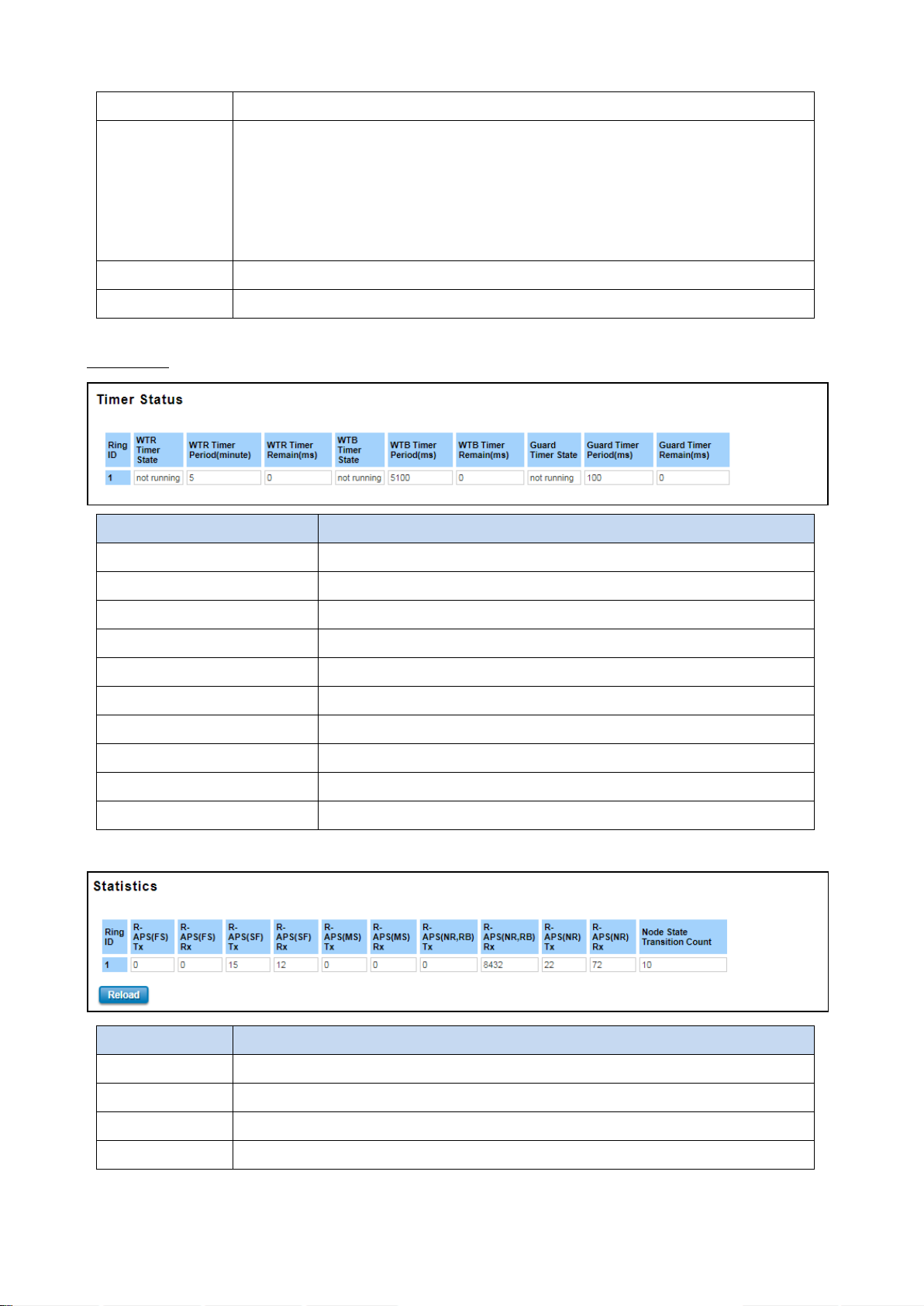
RPL Port
The port status as the RPL block.
Revertive Mode
Default: Revertive
Revertive mode, after the conditions causing a protection switch has cleared; the traffic
channel is restored to the working transport entity that is, blocked on the RPL. In
Non-Revertive mode, the traffic channel continues to use the RPL, if it is not failed, after
a protection switch condition has cleared.
Manual Switch
Status from the Ring Port 0 and 1 or None
Force Switch
Status from the Ring Port 0 and 1 or None
TERMS
DESCRIPTION
Ring ID
Display the Ring ID
WTR Timer State
Running or not Running status
WTR Timer Period (minute)
WTR timeout in milliseconds.
WTR Timer Remain (ms)
Remaining WTR timeout in milliseconds.
WTB Timer State
Running or not Running status
WTB Timer Period (ms)
WTB timeout in milliseconds.
WTB Timer Remain (ms)
Remaining WTB timeout in milliseconds.
Guard Timer State
Running or not Running status
Guard Timer Period (ms)
Guard Timer timeout in milliseconds.
Guard Timer Remain (ms)
Remaining Guard Timer timeout in milliseconds.
TERMS
DESCRIPTION
Ring ID
Display the Ring ID.
R-APS(FS) Tx
The number of R-APS messages with Forced Switch (FS) being sent.
R-APS(FS) Rx
The number of R-APS messages with Forced Switch (FS) being received.
R-APS(SF) Tx
The number of R-APS messages with Signal Fail (SF) being sent.
Timer Status
59
Page 60

R-APS(SF) Rx
The number of R-APS messages with Signal Fail (SF) being received.
R-APS(MS) Tx
The number of R-APS messages with Manual Switch (MS) being sent.
R-APS(MS) Rx
The number of R-APS messages with Manual Switch (MS) being received.
R-APS(NR, RB) Tx
The number of R-APS messages with a No Request, RPL Blocked (NR,RB) being sent.
R-APS(NR, RB) Rx
The number of R-APS messages with a No Request, RPL Blocked (NR,RB) being received.
R-APS(NR) Tx
The number of R-APS messages with a No Request (NR) being sent.
R-APS(NR) Rx
The number of R-APS messages with a No Request (NR) being received.
Node State
Transition Count
The number of state transition that detected in the Ring.
60
Page 61

TERMS
DESCRIPTION
Primary VLAN
The uplink port is usually the primary VLAN. A primary VLAN contains promiscuous ports
that can communicate with lower Secondary VLANs.
Secondary VLAN
The client ports are usually defined within secondary VLAN. The secondary VLAN includes
Isolated VLAN and Community VLAN. The client ports can be isolated VLANs or can be
grouped in the same Community VLAN. The ports within the same community VLAN can
communicate with each other.
3.5 VLAN
A VLAN is a group of devices that can be located anywhere on a network, but which communicate as if they are on
the same physical segment. With VLANs, User can segment User network without being restricted by physical
connections—a limitation of traditional network design. With VLANs User can segment User network into:
• Departmental groups—User could have one VLAN for the marketing department, another for the finance
department, and another for the product development department.
• Hierarchical groups—User could have one VLAN for directors, another for managers, and another for general staff.
• Usage groups—User could have one VLAN for email users and another for multimedia users.
Benefits of VLANs
The main benefit of VLANs is that they provide a network segmentation system that is far more flexible than
traditional networks. Using VLANs also provides User with three other benefits:
• VLANs ease the relocation of devices on networks: With a VLAN setup, if a host originally on the Marketing VLAN,
is moved to a port on another part of the network, and retains its original subnet membership, User only needs to
specify that the new port is on the Marketing VLAN. User does not need to do any re-cabling.
• VLANs provide extra security: Devices within each VLAN can only communicate with other devices on the same
VLAN. If a device on the Marketing VLAN needs to communicate with devices on the Finance VLAN, the traffic must
pass through a routing device or Layer 3 switch.
• VLANs help control traffic: VLANs increase the efficiency of User network because each VLAN can be set up to
contain only those devices that need to communicate with each other.
This switch also has private VLAN functions; it helps to resolve the primary VLAN ID shortage, client ports’ isolation
and network security issues. A private VLAN partitions the Layer 2 broadcast domain of a VLAN into subdomains,
allowing User to isolate the ports on the switch from each other. A subdomain consists of a primary VLAN and one or
more secondary VLANs. All VLANs in a private VLAN domain share the same primary VLAN. The secondary VLAN ID
differentiates one subdomain from another. The secondary VLANs may either be isolated VLANs or community
VLANs. A host on an isolated VLAN can only communicate with the associated promiscuous port in its primary VLAN.
Hosts on community VLANs can communicate among themselves and with their associated promiscuous port but
not with ports in other community VLANs. The Private VLAN provides primary and secondary VLAN within a single
switch.
61
Page 62
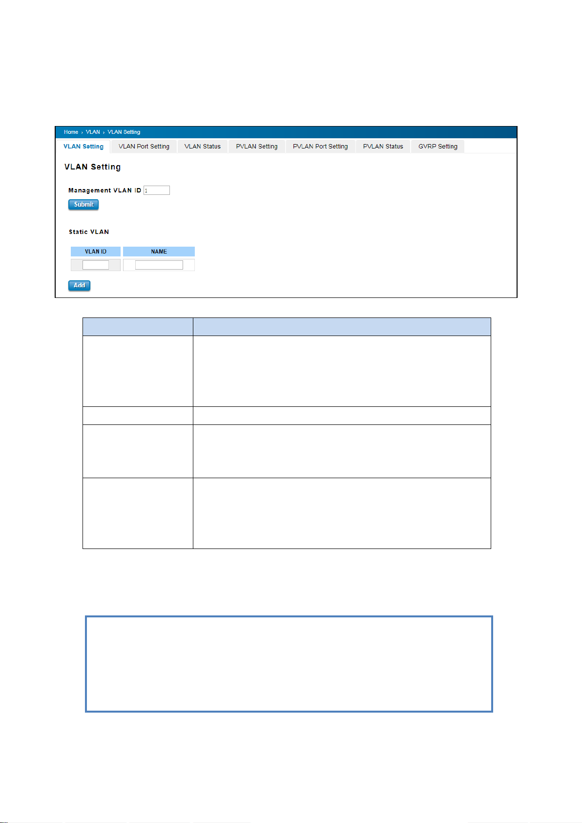
TERMS
DESCRIPTION
Management VLAN ID
Default : 1.
The switch supports management VLAN. The management VLAN ID is
the VLAN ID of the CPU interface so that only member ports of the
management VLAN can ping and access the switch.
Static VLAN
User can assign a VLAN ID and VLAN Name for new VLAN here.
VLAN ID
Default: 1
Used by the switch to identify different VLANs. Valid VLAN ID is
between 1 and 4094.
Name
A reference for network administrator to identify different VLANs. The
available character is 12 for User to input. If User don’t input VLAN
name, the system will automatically assign VLAN name for the VLAN.
The rule is VLAN (VLAN ID).
NOTE:
1. Before User changed the management VLAN ID by Web and Telnet, remember that the port
attached by the administrator should be the member port of the management VLAN;
otherwise the administrator can’t access the switch via the network.
2. WoMaster switch supports max 256 groups VLAN.
3.5.1 VLAN SETTING
To configure 802.1Q VLAN and port-based VLANs on the WoMaster switch, use the VLAN Settings page to configure
the ports. , User can assign Management VLAN, create the static VLAN, and assigns the Egress rule for the member
ports of the VLAN.
The description of the columns is as below:
The steps to create a new VLAN: Type in VLAN ID and NAME, and press Add to create a new VLAN. Then User can see
the new VLAN in the Static VLAN Configuration table. After created the VLAN, the status of the VLAN will remain in
Unused until User adds ports to the VLAN.
62
Page 63
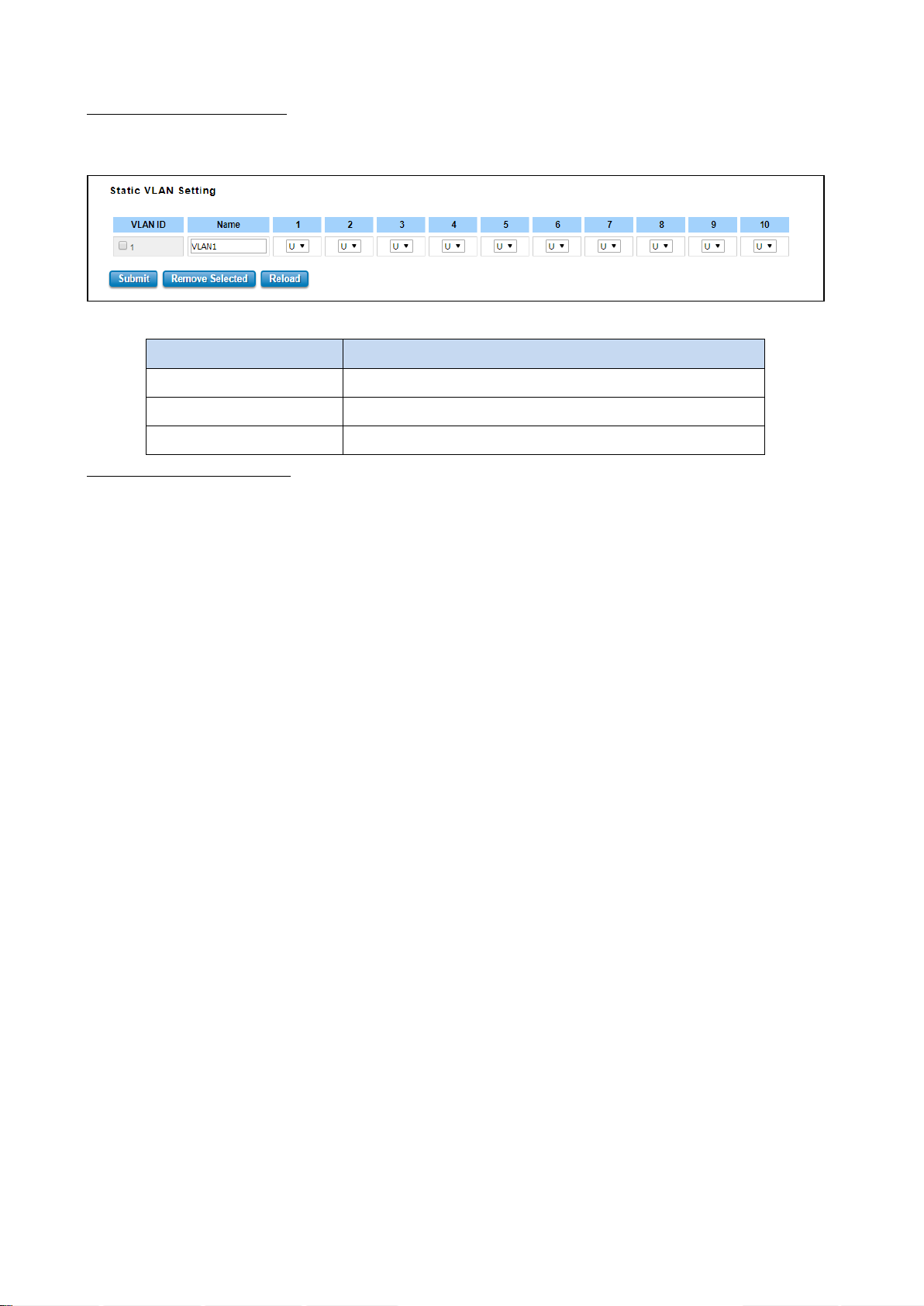
TERMS
DESCRIPTION
--
Not available
U/Untag
Indicates that egress/outgoing frames are not VLAN tagged.
T/Tag
Indicates that egress/outgoing frames are to be VLAN tagged.
Static VLAN Configuration
Static VLAN Configuration table is presented on the figure below. User can see the created VLANs and specify the
egress (outgoing) port rule to be Untagged or Tagged here.
The description of the columns is as below:
Steps to configure Egress rules :
Select the VLAN ID. Entry of the selected VLAN turns to light blue. Assign Egress rule of the ports to U or T. Press
Submit to apply the setting. If User wants to remove one VLAN, select the VLAN entry. Then press Remove button.
63
Page 64
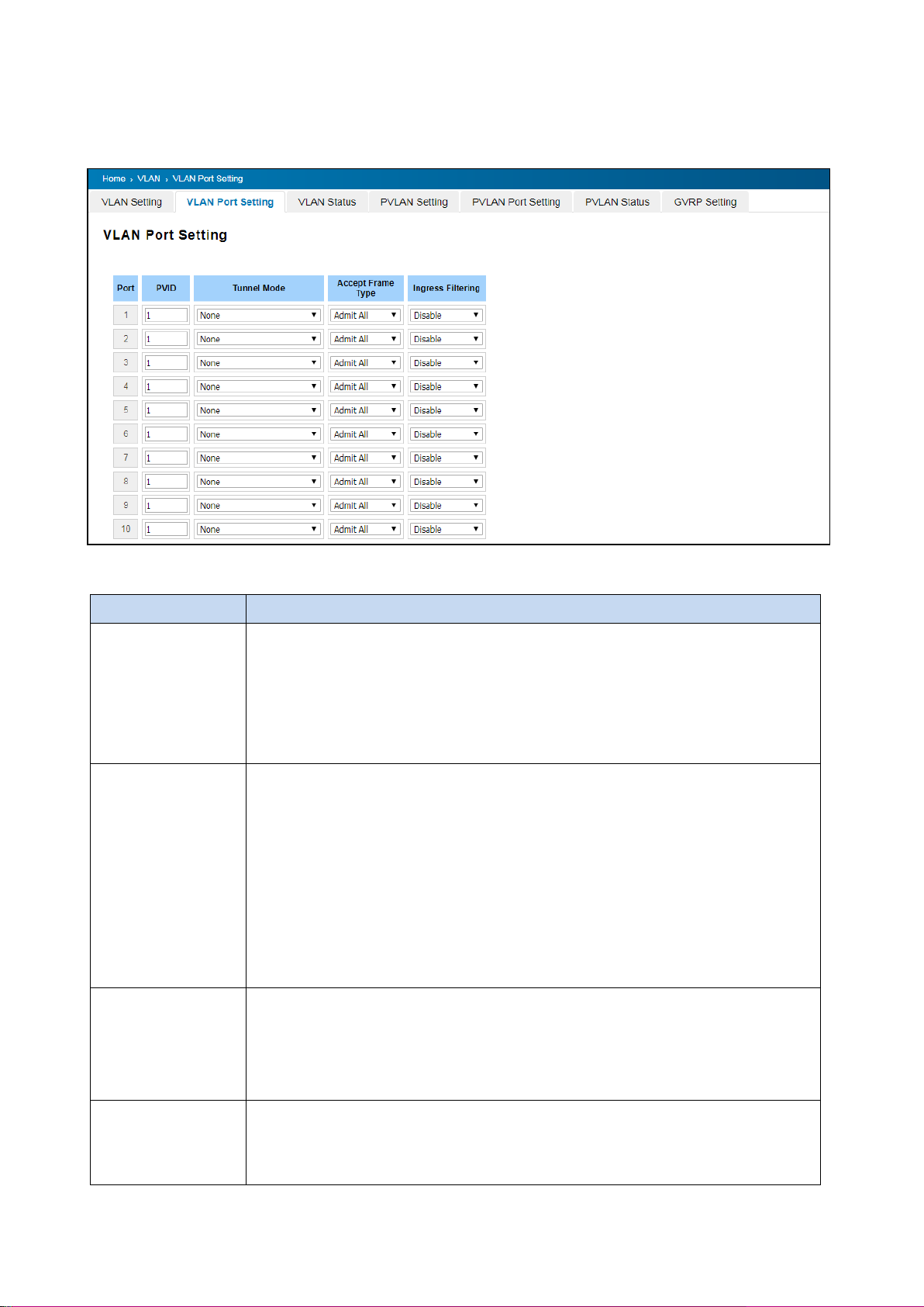
TERMS
DESCRIPTION
PVID
The abbreviation of the Port VLAN ID. PVID allows the switches to identify which port
belongs to which VLAN. To keep things simple, it is recommended that PVID is
equivalent to VLAN IDs. The values of PVIDs are from 0 to 4095. But, 0 and 4095 are
reserved. User can’t input these 2 PVIDs. 1 is the default value. 2 to 4094 are valid and
available in this column.
Tunnel Mode
Default: None
None : This is Port that no using Q in Q
802.1Q Tunnel: As the Ingress port, is connected to the client port. Configures Q in Q
tunneling for a client access port to segregate and preserve customer VLAN IDs for
traffic crossing the service provider network.
802.1Q Tunnel Uplink: As the egress port, that is, the middle switch port. Configures Q
in Q tunneling for an uplink port to another device within the service provider network.
802.1Q Tunnel Uplink-Add-PVID: Assign second VLAN tag for specify VLANs.
Accept Frame Type
This column defines the accepted frame type of the port. There are 2 modes User can
select, Admit All and Tag Only. Admit All mode means that the port can accept both
tagged and untagged packets. Tag Only mode means that the port can only accept
tagged packets.
Ingress Filtering
Ingress filtering helps VLAN engine to filter out undesired traffic on a port. When Ingress
Filtering is enabled, the port checks whether the incoming frames belong to the VLAN
they claimed or not. Then the port determines if the frames can be processed or not.
3.5.2 VLAN PORT SETTING
VLAN Port Setting allows User to setup VLAN port parameters to specific port.
The description of the columns is as below:
64
Page 65
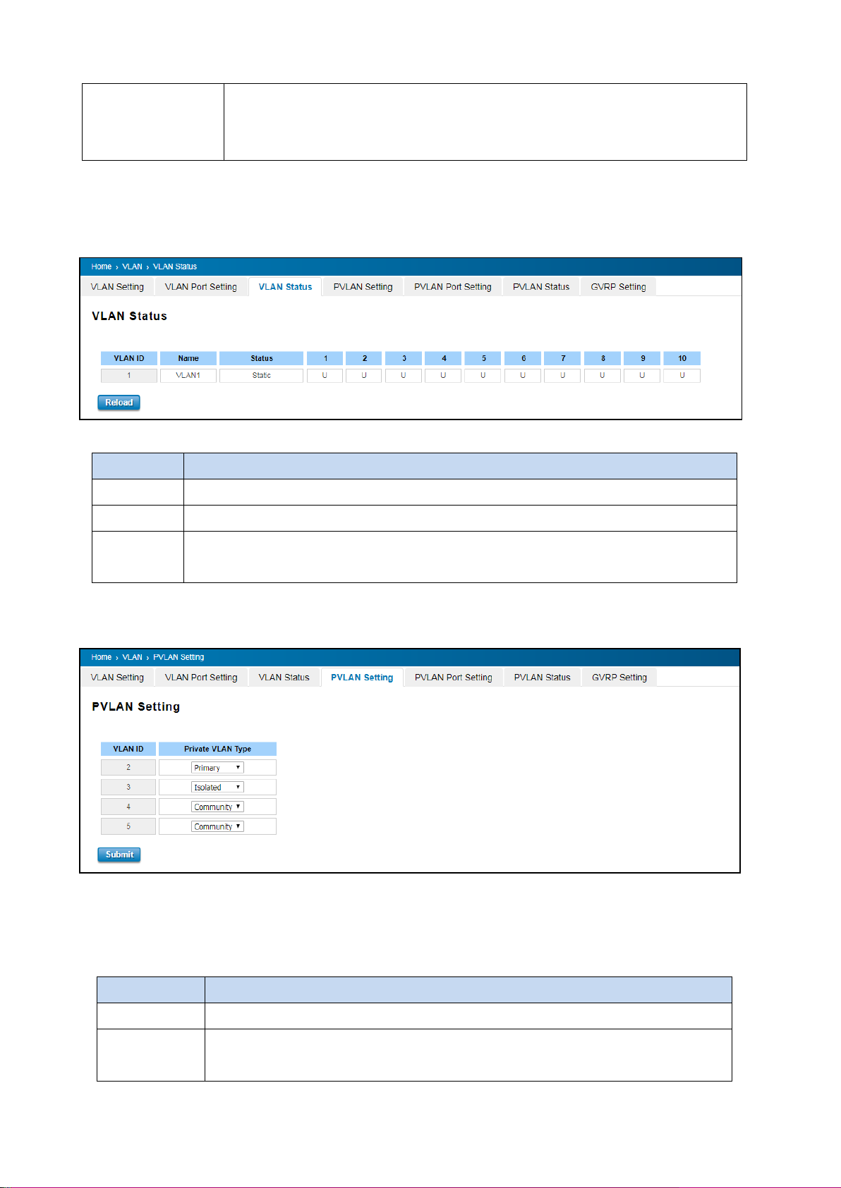
For example, if a tagged frame from Engineer VLAN is received, and Ingress Filtering is
enabled, the switch will determine if the port is on the Engineer VLAN’s Egress list. If it
is, the frame can be processed. If it’s not, the frame would be dropped.
TERMS
DESCRIPTION
VLAN ID
ID of the VLAN.
Name
Name of the VLAN.
Status
Static shows this is a manually configured static VLAN. This VLAN is not workable yet.
Dynamic means this VLAN is learnt by GVRP.
TERMS
DESCRIPTION
None
The VLAN is not included in Private VLAN.
Primary
The VLAN is the Primary VLAN. The member ports can communicate with secondary
ports.
3.5.3 VLAN STATUS
This table shows User current status of User VLAN, including VLAN ID, Name, Status, and Egress rule of the ports.
The description of the columns is as below:
After created the VLAN, the status of this VLAN will remain in unused status until User adds ports to the VLAN.
3.5.4 PVLAN SETTING
The figure above is PVLAN Setting interface. PVLAN Configuration allows User to assign Private VLAN type. After
created VLAN in VLAN Configuration page, the available VLAN ID will display here. Choose the Private VLAN types for
each VLAN User wants configure.
The description of the columns is as below:
65
Page 66
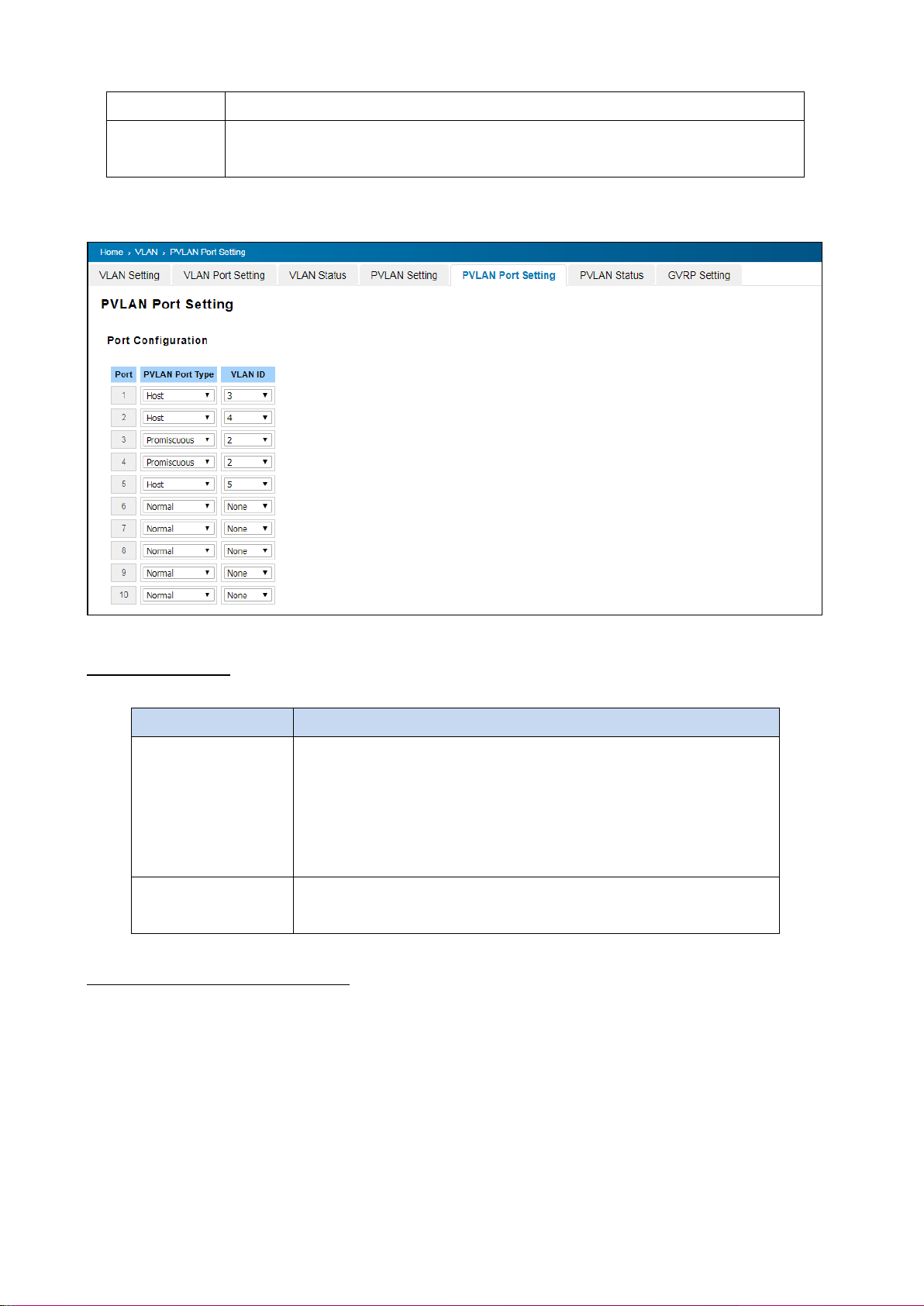
Isolated
The VLAN is the Isolated VLAN. The member ports of the VLAN are isolated.
Community
The VLAN is the Community VLAN. The member ports of the VLAN can communicate
with each other.
TERMS
DESCRIPTION
PVLAN Port Type
Normal: The Normal port is None PVLAN ports; it remains its original
VLAN setting.
Host: The Host type ports can be mapped to the Secondary VLAN.
Promiscuous: The promiscuous port can be associated to the Primary
VLAN.
VLAN ID
After assigned the port type, the web UI display the available VLAN ID the
port can associate to.
3.5.5 PVLAN PORT SETTING
PVLAN Port Setting page allows configure Port Configuration and Private VLAN Association.
Port Configuration
The description of the columns is as below:
Private VLAN Association (PVLAN)
Secondary VLAN: Secondary VLAN is included Isolated and Community VLAN Type that assigned in Private
VLAN Configuration section. User can select the Secondary VLAN ID here.
Primary VLAN: Primary VLAN is included the Primary VLAN Type that assigned in Private VLAN Configuration
section. User can select the Primary VLAN ID here.
66
Page 67
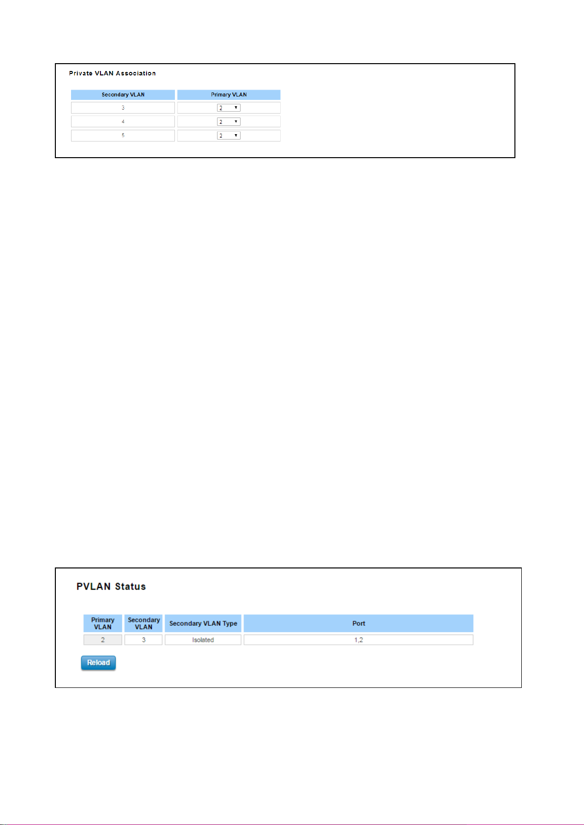
Before configuring PVLAN port type, the Private VLAN Association should be done first.
For example:
1. VLAN Create: VLAN 2-5 are created in VLAN Configuration section.
2. Private VLAN Type: VLAN 2-5 has its Private VLAN Type configured in Private VLAN Configuration page.
VLAN 2 is belonged to Primary VLAN. VLAN 3-5 are belonged to secondary VLAN (Isolated or Community).
3. Private VLAN Association: Associate VLAN 3-5 as the Secondary VLAN to VLAN 2 as the Primary VLAN in
Private VLAN Association first.
4. Private VLAN Port Configuration
VLAN 2 – Primary -> The member port of VLAN 2 is promiscuous port.
VLAN 3 – Isolated -> The Host port can be mapped to VLAN 3.
VLAN 4 – Community ->The Host port can be mapped to VLAN 3.
VLAN 5 – Community ->The Host port can be mapped to VLAN 3.
5. Result:
VLAN 2 -> VLAN 3, 4, 5; member ports can communicate with ports in secondary VLAN.
VLAN 3 -> VLAN 2, member ports are isolated, but it can communicate with member port of VLAN 2..
VLAN 4 -> VLAN 2, member ports within the community can communicate with each other and communicate
with member port of VLAN 2.
VLAN 5 -> VLAN 2, member ports within the community can communicate with each other and communicate
with member port of VLAN 2.
3.5.6 PVLAN STATUS
This page allows User to see the Private VLAN status information.
67
Page 68
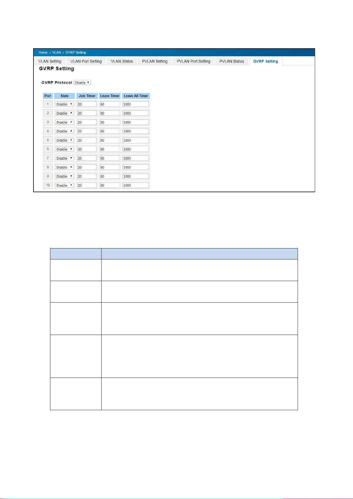
TERMS
DESCRIPTION
GVRP Protocol
Default: Disable
Allow user to enable / disable GVRP function globally.
State
Default: Disable
After enable GVRP globally, here still can enable/disable GVRP by port.
Join Timer
Default: 20
Controls the interval of sending the GVRP Join BPDU. An instance of this timer
is required on a per-Port, per-GARP Participant basis
Leave Timer
Default: 60
Control the time to release the GVRP reservation after received the GVRP
Leave BPDU. An instance of the timer is required for each state machine that is
in the LV state.
Leave All Timers
Default: 1000
Controls the period to initiate the garbage collection of registered VLAN. The
timer is required on a per-Port, per-GARP Participant basis
3.5.7 GVRP SETTING
GVRP (GARP VLAN Registration Protocol) is a protocol that facilitates control of virtual local area networks (VLANs)
within a larger network. GVRP conforms to the IEEE 802.1Q specification, which defines a method of tagging frames
with VLAN configuration data. This allows network devices to dynamically exchange VLAN configuration information
with other devices. GVRP allows users to set-up VLANs automatically rather than manual configuration on every port
of every switch in the network. The description of the columns is as below:
68
Page 69
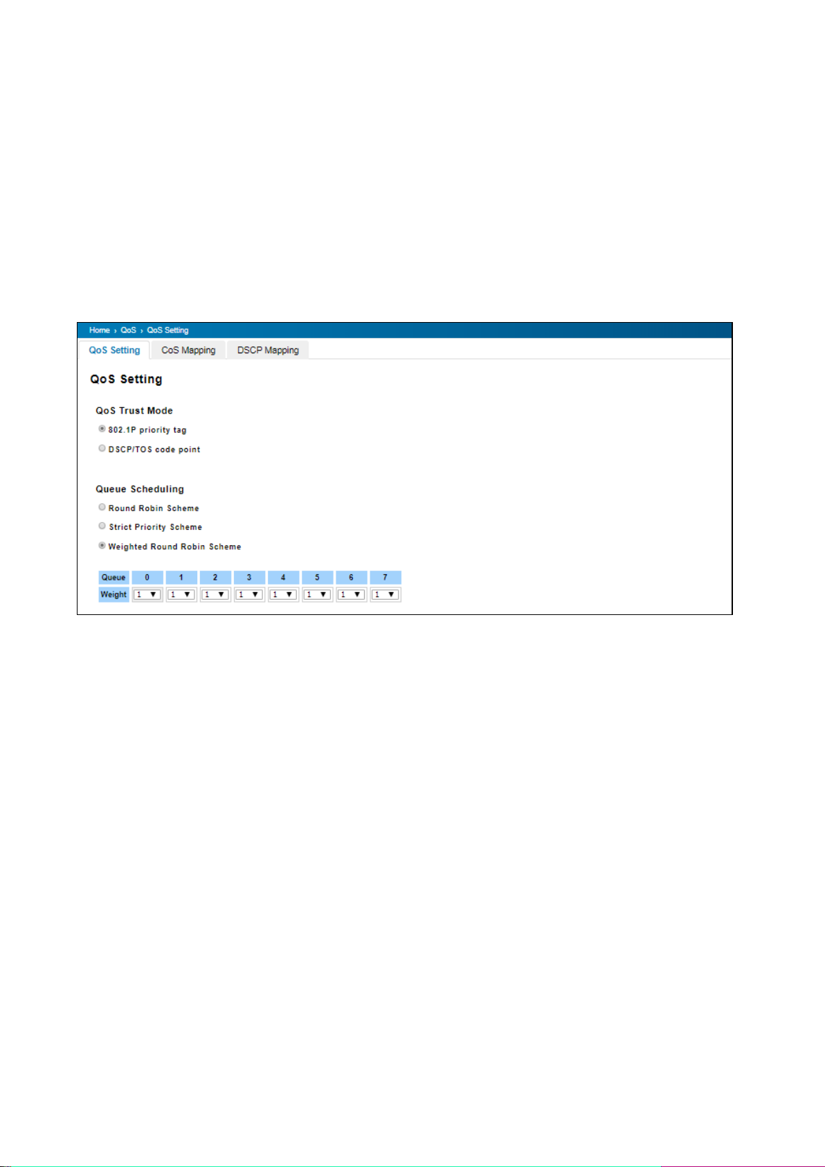
3.6 QUALITY of SERVICE (QoS)
Quality of Service (QoS) is the ability to provide different priority to different applications, users or data flows, or to
guarantee a certain level of performance to a data flow. QoS guarantees are important if the network capacity is
insufficient, especially for real-time streaming multimedia applications. QoS can also help to reduce traffic problems
and ensure high-priority traffic is delivered first. This section allows User to configure Traffic Prioritization settings for
each port with regard to setting priorities.
3.6.1 QoS SETTING
The figure below shows QoS Setting.
QoS Trust Mode
802.1P Priority Tag: If 802.1P is selected the switch relies on a packet's CoS information to determine priority. This is
related to the settings in the CoS-Queue Mapping page
DSCP/TOS Code Point: If DSCP/TOS is selected the switch relies on a packets differentiated services code point
information to determine the priority. This is related to the settings in the DSCP-Priority Mapping page.
Queue Scheduling
Select the Queue Scheduling rule:
- Use Round Robin Scheme: The Round Robin scheme means all the priority has the same privilege, the traffic
is forward cyclic from highest to lowest.
- Use strict priority scheme: The priority here always the higher queue will be processed first, except the higher
queue is empty.
- Use Weighted Round Robin scheme. This scheme allows users to assign new weight ratio for each class. The
10 is the highest ratio. The ratio of each class is as below:
Wx / W0 + W1 + W2 + W3 + W4 + W5 + W6 + W7 (To tal volume of Queue 0-7)
69
Page 70
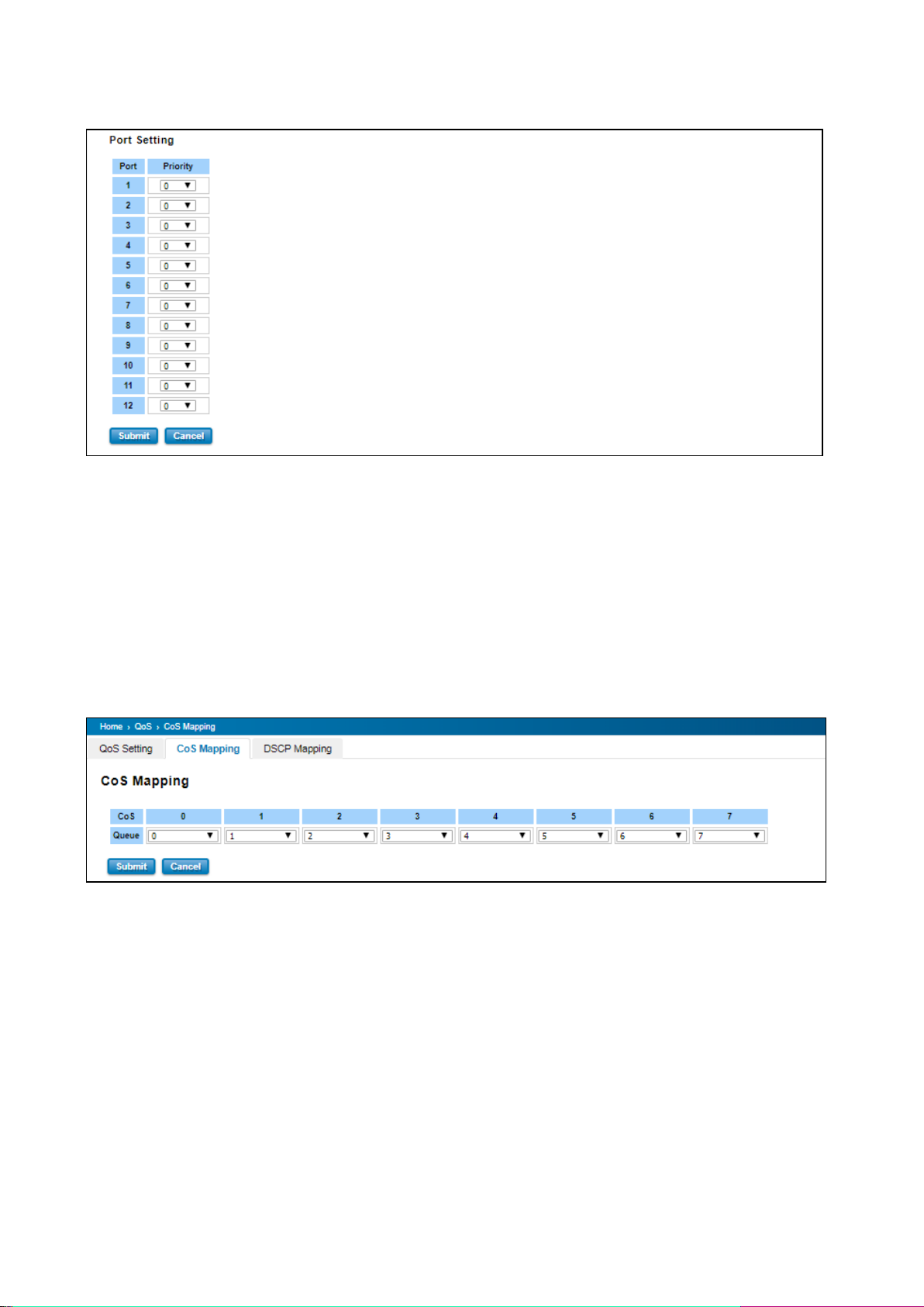
Port Setting
Choose the Queue value of each port, the port then has its default priority. The Queue 7 is the highest port-based
queue, 0 is the lowest queue. The traffic injected to the port follows the queue level to be forwarded, but the
outgoing traffic does not bring the queue level to next switch. Click the Apply button to apply the configuration
changes.
3.6.2 CoS MAPPING
This section allows user to change CoS values to Physical Queue mapping table. WoMaster switch only supports 4
physical queues, Lowest, Low, Middle and High represent by numbers from 0 to 3. In WoMaster switch, users can
freely assign the mapping table or follow the suggestion of the 802.1p standard. Below is the interface.
User can find CoS values 1 and 2 are mapped to physical Queue 0, the lowest queue. CoS values 0 and 3 are mapped
to physical Queue 1, the low/normal physical queue. CoS values 4 and 5 are mapped to physical Queue 2, the middle
physical queue. CoS values 6 and 7 are mapped to physical Queue 3, the high physical queue. After configuration,
press Submit to enable the settings.
70
Page 71
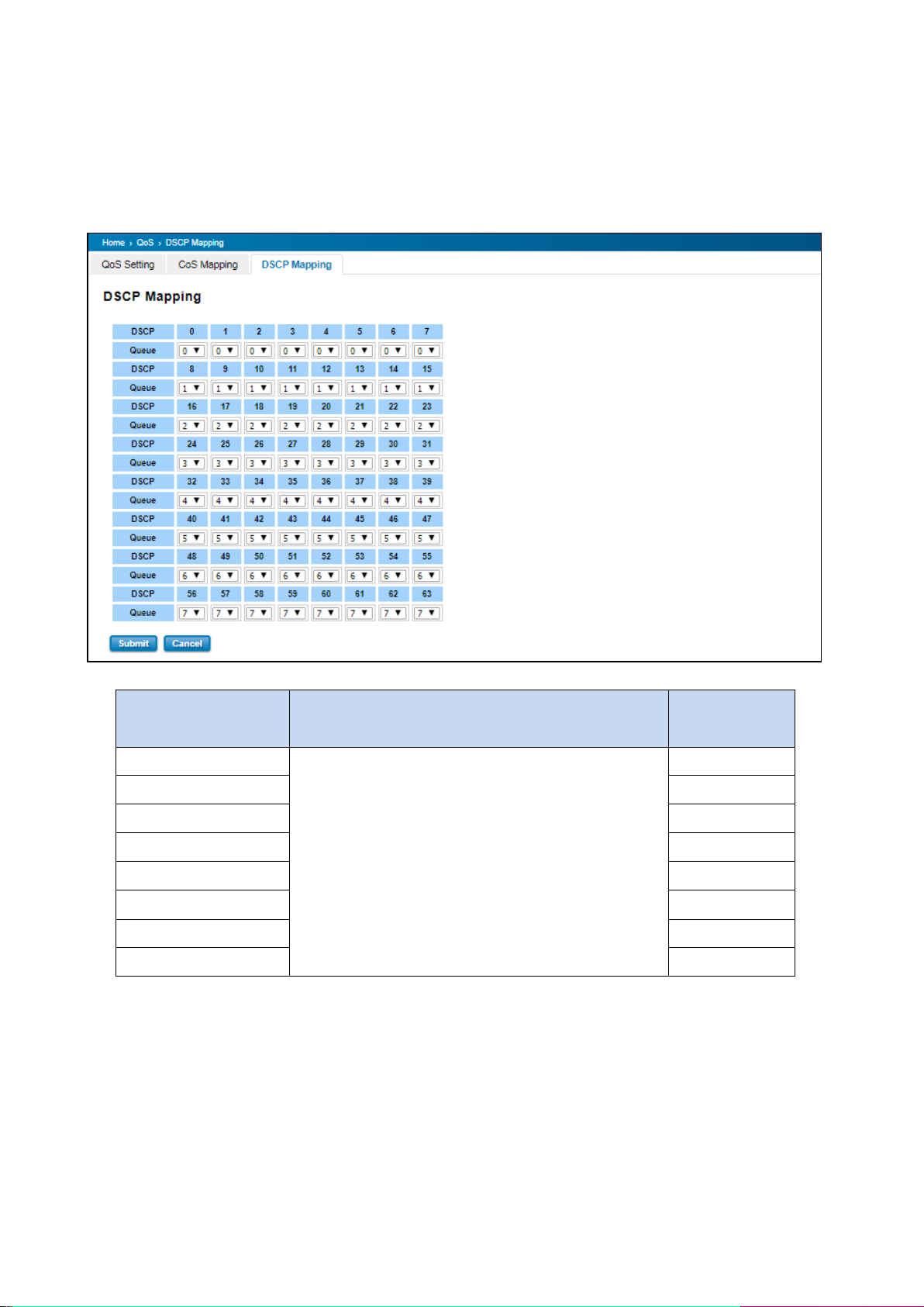
DSCP Value and Priority
Queues Setting
Description
Factory Default
0 to 7
Maps different TOS values to one of 8 different egress
queues.
0
8 to 15
1
16 to 23
2
24 to 31
3
32 to 39
4
40 to 47
5
48 to 55
6
56 to 63
7
3.6.3 DSCP MAPPING
This page is to change DSCP values to Physical Queue mapping table. Since the switch fabric only supports 4 physical
queues, Lowest, Low, Middle and High. Users should therefore assign how to map DSCP value to the level of the
physical queue. Users can freely change the mapping table to follow the upper layer 3 switch or routers’ DSCP
setting.
After configuration, press Submit to enable the settings.
71
Page 72

MESSAGE
DESCRIPTION
Query
A message sent from the querier (an IGMP router or a switch) which asks for
a response from each host that belongs to the multicast group.
Report
A message sent by a host to the querier to indicate that the host wants to be
or is a member of a given group indicated in the report message.
Leave Group
A message sent by a host to the querier to indicate that the host has quit as
a member of a specific multicast group.
3.7 MULTICAST
Multicasts are similar to broadcasts, they are sent to all end stations on a LAN or VLAN. Multicast filtering is the
function, which end stations can receive the multicast traffic if the connected ports had been included in the specific
multicast groups. With multicast filtering, network devices only forward multicast traffic to the ports that are
connected to the registered end stations. For multicast filtering, WoMaster’ switch uses IGMP Snooping technology.
IGMP (Internet Group Management Protocol) is an Internet Protocol that provides a way for internet device to
report its multicast group membership to adjacent routers. In effect, IGMP Snooping manages multicast traffic by
making use of switches, routers, and hosts that support IGMP. IGMP has three fundamental types of messages, as
shown below:
User can enable IGMP Snooping and IGMP Query functions in this section. User will see the information of the IGMP
Snooping function in this section, including different multicast groups’ VID and member ports, and IP multicast
addresses that range from 224.0.0.0 to 239.255.255.255.
In this section, Force filtering can determine whether the switch flooding is unknown multicast or not.
Following commands are included in this group:
3.7.1 IGMP Query
3.7.2 IGMP Snooping
3.7.3 GMRP Setting
72
Page 73
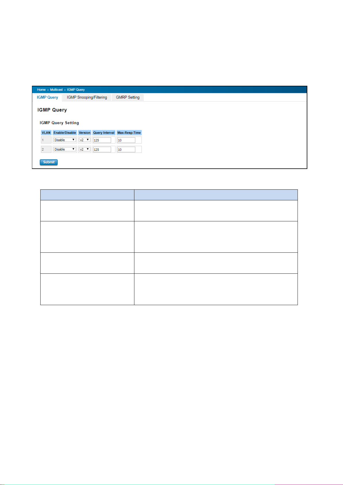
TERMS
DESCRIPTION
Enable
Default: Disable
Enable the IGMP Query function
Version
Default: V2
V1 means IGMP V1 General Query
V2 means IGMP V2 General Query.
Query Interval(s)
Default: 125
The period of query sent by querier.
Max-Resp-Time
Default: 10
The span querier detects to confirm there are no more directly
connected group members on a LAN.
3.7.1 IGMP QUERY
This page allows users to configure IGMP Query feature. Since the device can only be configured by member ports
of the management VLAN, IGMP Query can only be enabled on the management VLAN. If User wants to run IGMP
Snooping feature in several VLANs, User should notice that whether each VLAN has its own IGMP Querier first.
The IGMP querier periodically sends query packets to all end-stations on the LANs or VLANs that are connected to it.
For networks with more than one IGMP querier, a switch with the lowest IP address becomes the IGMP querier.
Once User finished configuring the settings, click on Submit to apply User configuration.
73
Page 74
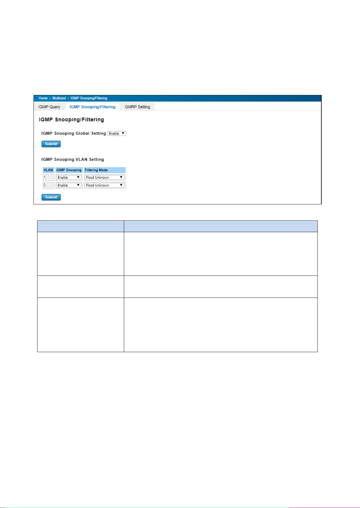
TERMS
DESCRIPTION
IGMP Snooping Global Setting
User can select Enable or Disable here. After enabling IGMP Snooping, User
can then enable IGMP Snooping for specific VLAN. User can enable IGMP
Snooping for some VLANs so that some of the VLANs will support IGMP
Snooping and others won’t.
IGMP Snooping
Select the Enable to activate the IGMP Snooping. In the same way, User can
also Disable IGMP Snooping for certain VLANs.
Filtering Mode
It allows the switch to filter the unknown-multicast data flow. Multicast
Filtering Mode is Flood unknown, discard unknown and source only
learning.
- Flood Unknown: The switch would filter the unknown packets that
transmit through the network
3.7.2 IGMP SNOOPING
This page is to enable IGMP Snooping feature, assign IGMP Snooping for specific VLAN, and view IGMP Snooping
table from dynamic learnt or static manual key-in. WoMaster’ Switch support IGMP snooping V1/V2/V3
automatically and IGMP query V1/V2. Enabling IGMP Snooping allows the ports to detect IGMP queries, report
packets, and manage multicast traffic through the switch.
74
Page 75
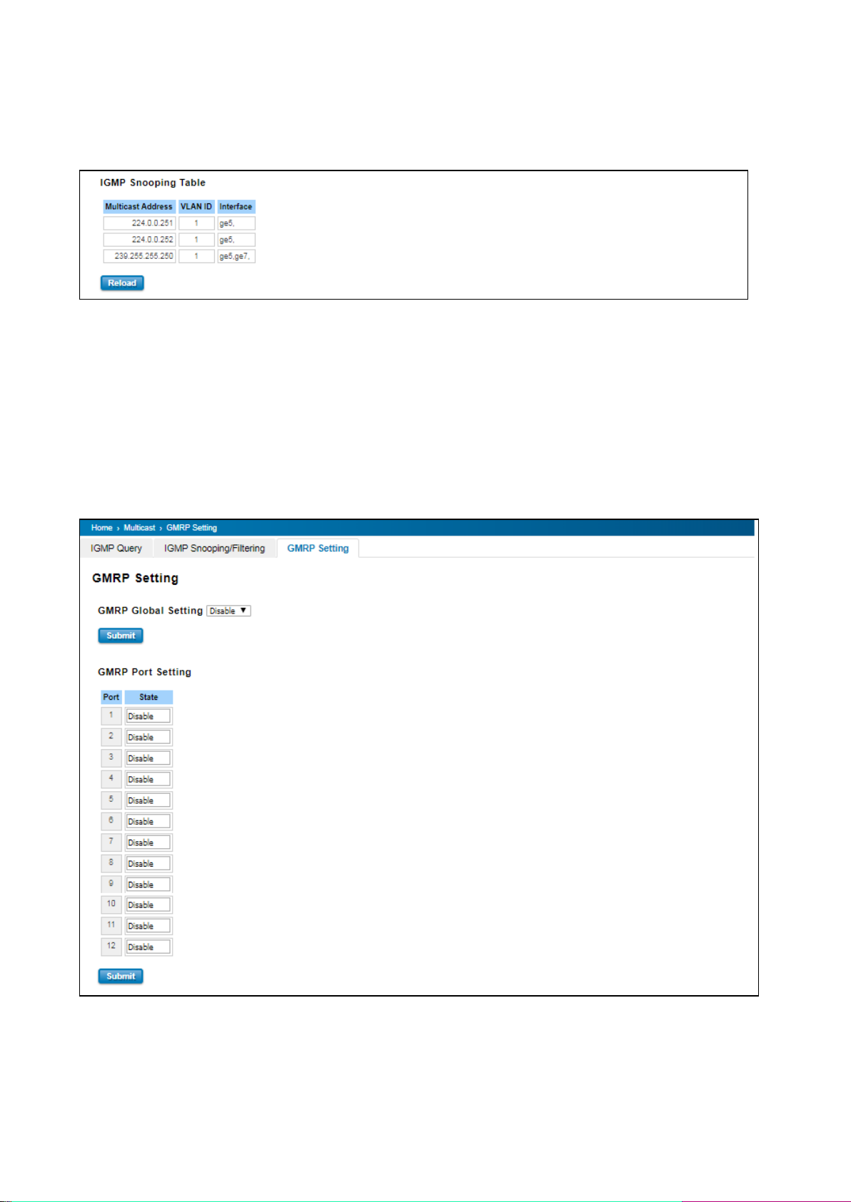
IGMP Snooping Table: In the table, User can see multicast group IP address, VLAN ID it belongs to, and member
ports of the multicast group. WoMaster Managed Switch series supports 256 multicast groups. Click on Reload to
refresh the table.
3.7.3 GMRP SETTING
GARP Multicast Registration Protocol (GMRP) is a Generic Attribute Registration Protocol (GARP) application that
provides a constrained multicast flooding facility similar to IGMP snooping. GMRP and GARP are industry-standard
protocols defined by the IEEE 802.1P. The GMRP Setting allows bridges and end stations to dynamically register group
membership information with the MAC bridges attached to the same LAN segment and for that information to be
disseminated across all bridges in the Bridged LAN that supports extended filtering services. Enable to activate the
function.
75
Page 76
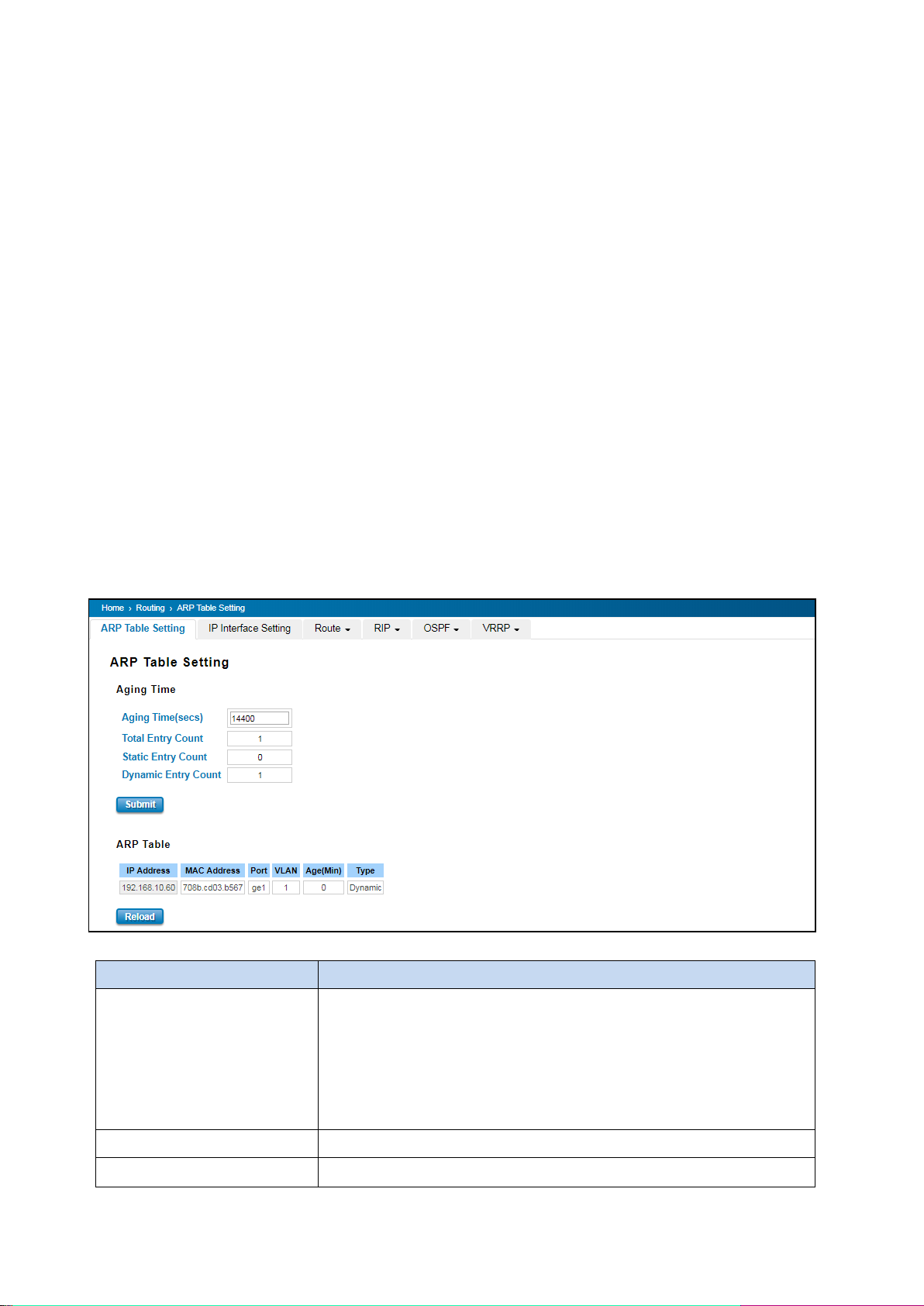
TERMS
DESCRIPTION
Aging Time (secs)
Default: 14400 seconds
Set the Age time for the ARP entry. Once there is no packet (IP+MAC) hit
the entry within the time, the entry will be aged out. Short ARP age time
leads the entry aged out easier and re-learn often, the re-learn progress
lead the communication stop.
Total Entry Count
Count of total entries from the ARP Table.
Static Entry Count
Count the static entries that user configured.
3.8 ROUTING
Routing Feature is the most important feature of the Layer 3 Switch. Layer 3 routing feature is requested since the
hosts located in different broadcast domain can’t communicate each other, once there is a need to communicate
among the different VLANs. WoMaster Switch combines Layer 2 switching and Layer 3 routing within the single
platform. In the Routing Configuration pages allows users create the Routing Interfaces, enable routing capability,
enable unicast/multicast routing protocols, configure router redundancy policy and check the related routing
information.
3.8.1 ARP TABLE SETTING
Address Resolution Protocol is a network layer protocol that query by broadcast and reply by unicast packet format.
It assists IP protocol to get the MAC address of an IP destination due to the unique MAC address in the network. It is
so important to find out the destination MAC address so then the traffic can be correctly and smoothly directed to
the destination.
An ARP table is include the table with MAC Address/IP Address, and keep the information from the ARP reply, saving
ARP operation for frequent communication and the entries are timeout with an aging mechanism. Below is the
configuration page that allows user to configure the Age Time of the ARP entry and see the count of static and
dynamic entry count.
76
Page 77
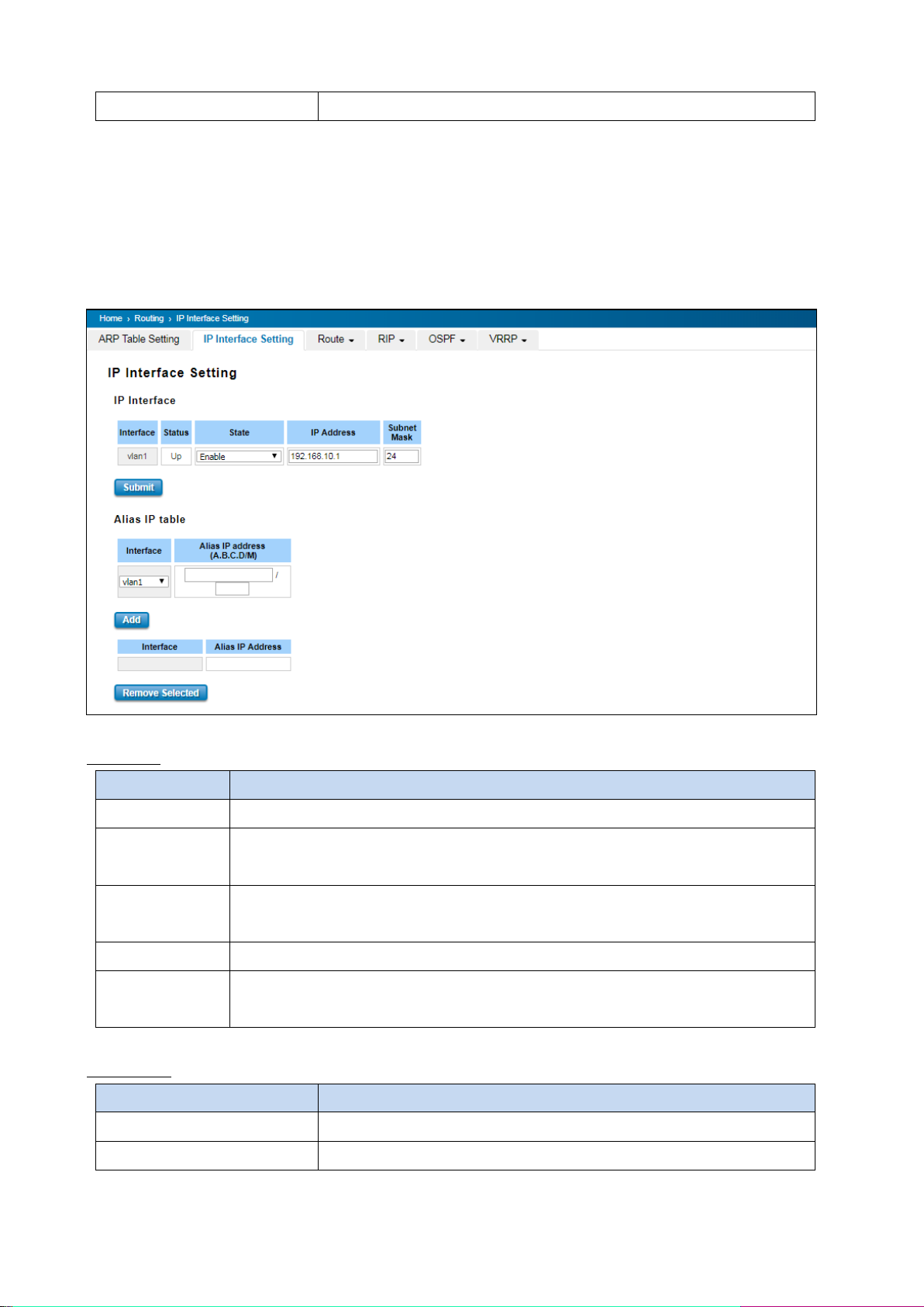
Dynamic Entry Count
Count the ARP table dynamically learnt.
TERMS
DESCRIPTION
Interface
The name of the IP interface.
Status
After enabled the routing state, the Status shows Up. After disabled the routing state, the
status shows Down
State
Enable or Disable the IP Routing Interface state. After disabled, the interface just work as
a layer 2 VLAN. After enabled, the interface can support IP routing feature.
IP Address
Assign the IP Address for the target IP Interface.
Subnet Mask
Choose the subnet mask here. For example, 255.255.255.0 represents for the typical Class
C, or so-call 24-bits mask. There are 256 IP Addresses within the range.
TERMS
DESCRIPTION
Interface
Select the interface.
Alias IP Address (A.B.C.D/M)
The alias IP and its subnet mask
Click Submit to apply the configuration.
3.8.2 IP INTERFACE SETTING
Through this page, user is allowed to enable the IP Routing interface and assign the IP Address. First create the VLAN
Interface and assign the member port to the VLAN before creating IP Interface, please refer to the VLAN
Configuration page. The IP Interface table listed all the created VLAN automatically; user can change the setting for
each VLAN here.
IP Interface
Alias IP Table
77
Page 78
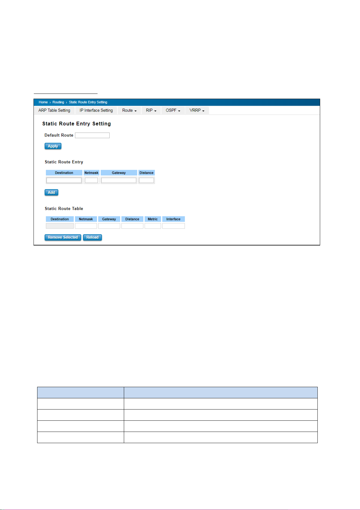
TERMS
DESCRIPTION
Destination
The destination address of static route entry.
Netmask
The destination address netmask of static route entry.
Gateway
The gateway IP address of static route entry.
Distance
The distance of static route entry.
Click the Add to add an alias IP address for the selected interface. Click the Remove Selected to remove the selected
alias IP address of an interface.
3.8.3 ROUTE
This configuration page allowed user to configure the route entry and display the route table.
Static Route Entry Setting
Default Route
The default route allows the stub network to reach all unknown networks through the route. The stub area has only
one way and one route to other networks. Within the stub area, there are multiple networks and run their own
routing protocols, however, while the want communicate with unknown network, the traffic will be forwarded to
the default route. While configuring Default Route, the IP address of the next hop router/switch is the only setting
needs to be specified.
Static Route Entry
Static route entries go to and go from a stub network to another stub network. The static route is usually configured
to connect the neighbor router/switch; the both routers/switches then can communicate through the route.
While configuring Static Route, all the fields in Route entry like the destination network and its netmask, the valid
route interface to the destination and distance are needed to be specified.
Click the Add button to add a static route entry.
78
Page 79
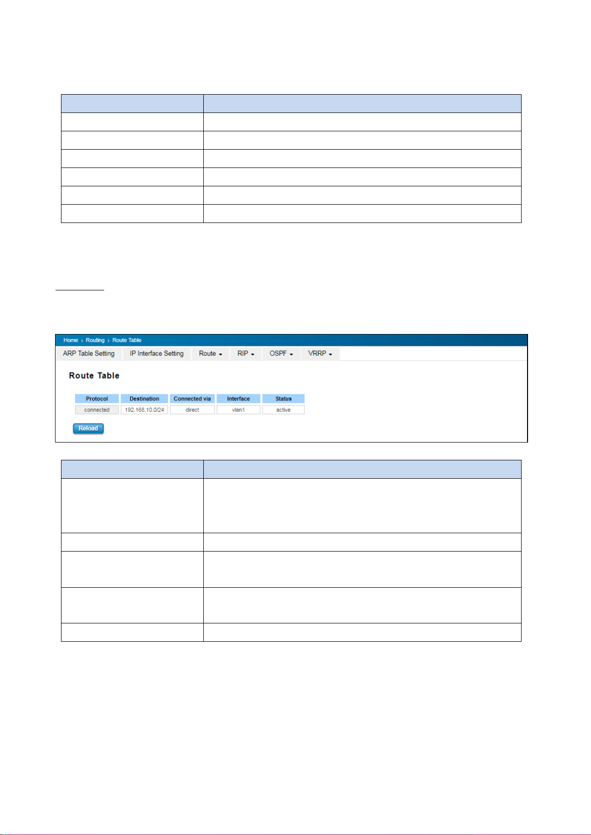
TERMS
DESCRIPTION
Destination
The destination address of static route entry.
Netmask
The destination address netmask of static route entry.
Gateway
The gateway IP address of static route entry.
Distance
The distance of static route entry.
Metric
The metric of static route entry.
Interface
The IP interface of static route entry.
TERMS
DESCRIPTION
Protocol
The field shows the entry is a local interface or learnt from the routing
protocol. The connected represents for the local interface. The OSPF shows
the entry is learnt from the routing protocol, OSPF.
Destination
The destination address of static route entry.
Connected via
The IP interface wherever the network learnt from. The interface is usually
the next hop’s IP address.
Interface
Show the VLAN Interface wherever the network connected to or learnt
from.
Status
Shows the entry status is active or not.
Static Route Table
This table displays the routing table information after user adds the static route entry form.
Click the Remove Selected button to remove selected route entry. Click the Reload button to reload Route Entry
Table information.
Route Table
Once the routing interfaces changed, the system maintains information and updates the routing table. It is important
to find out the possible and best route in the field especially when troubleshooting the network problem.
79
Page 80
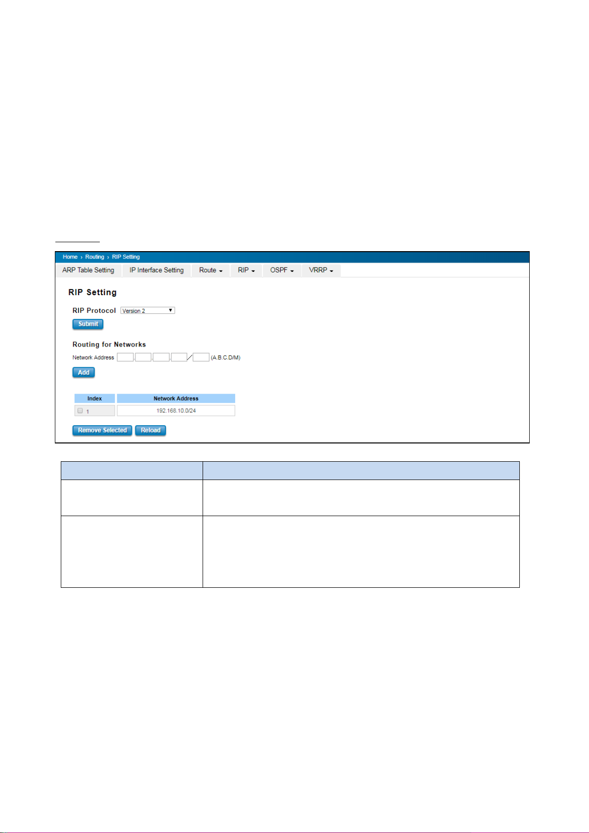
TERMS
DESCRIPTION
RIP Protocol
Choose the RIP Version 1 or Version 2 or Disable RIP protocol in here.
Click the Apply button to apply RIP protocol setting.
Routing for Networks
All the networks no matter directly connected or learnt from other
router/switch should be added to the switch. The format is IP Network/bit
mask. For example, 192.168.10.0/24. After type the network address, click
the Add to add a routing network.
3.8.4 RIP
Routing Information Protocol was in widespread use years before it was standardized in as RFC 1058 in 1988 and the
version 2 of RIP was completed in 1994. RIP is the most known Distance Vector type dynamic routing protocol, or
known as Hop Based routing protocol. It uses hop count as a distance metric, each router advertises its routing table
every 30 seconds. The maximum routers RIP can support is 15, the 16th router represents Infinity.
When a router receives a neighbor’s table, it examines it entry by entry. If the destination is new, it is added to the
local routing table. If the destination is known before and the update provides a smaller metric, the existing entry in
the local routing table is replaced. Adds 1 (or sometimes more if the corresponding link is slow) to the metric. If no
route updated within the cycles, the entry is removed.
RIP Setting
Click the Add button to add a routing network. Click the Remove Selected button to remove selected network
address. Click the Reload button to reload RIP information.
80
Page 81
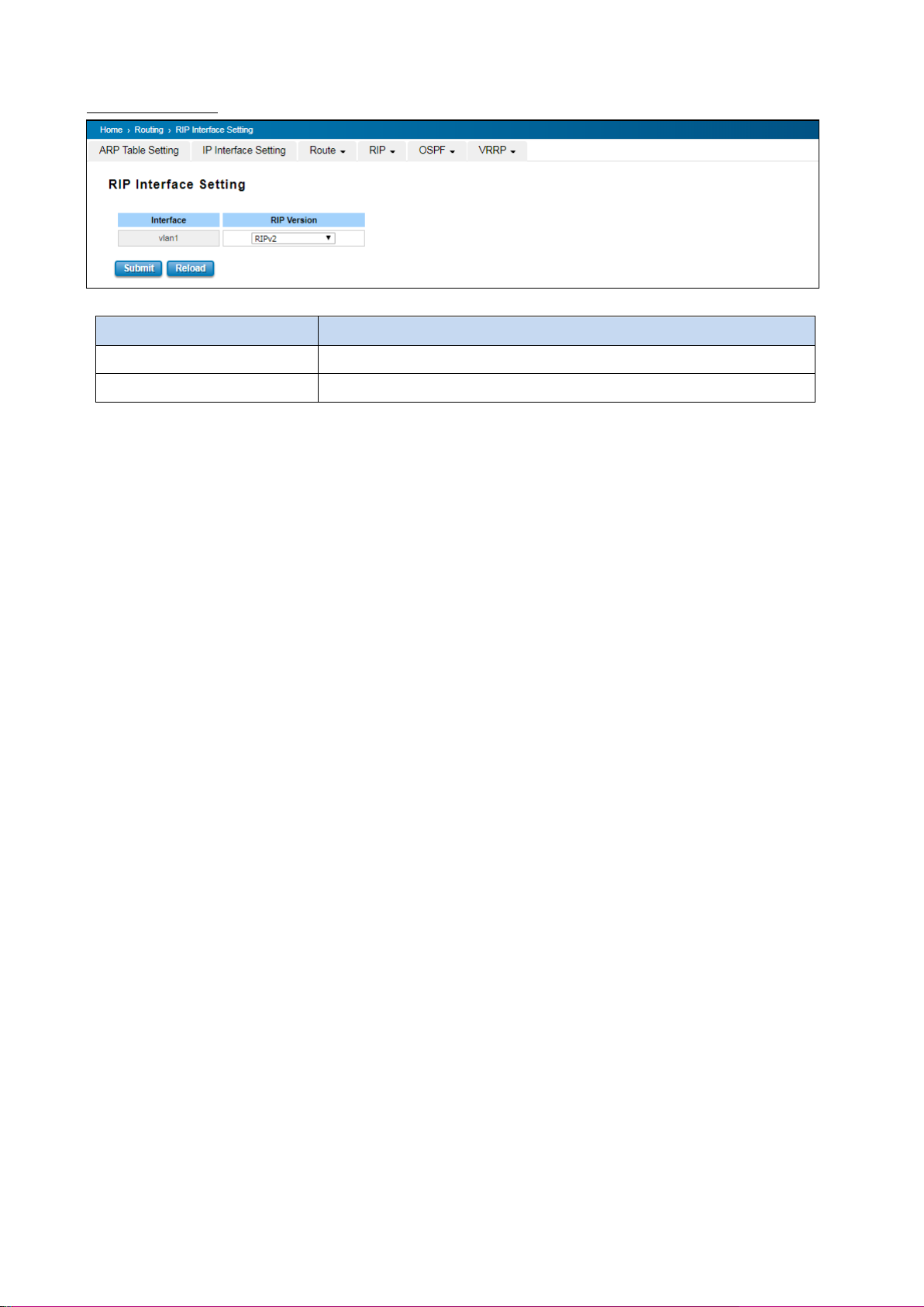
TERMS
DESCRIPTION
Interface
The IP interface.
RIP Version
RIP version of IP interface. (RIPv1, RIPv2 and Both)
RIP Interface Setting
Click the Submit button to apply RIP interface settings. Click the Reload button to reload RIP interface configuration.
81
Page 82
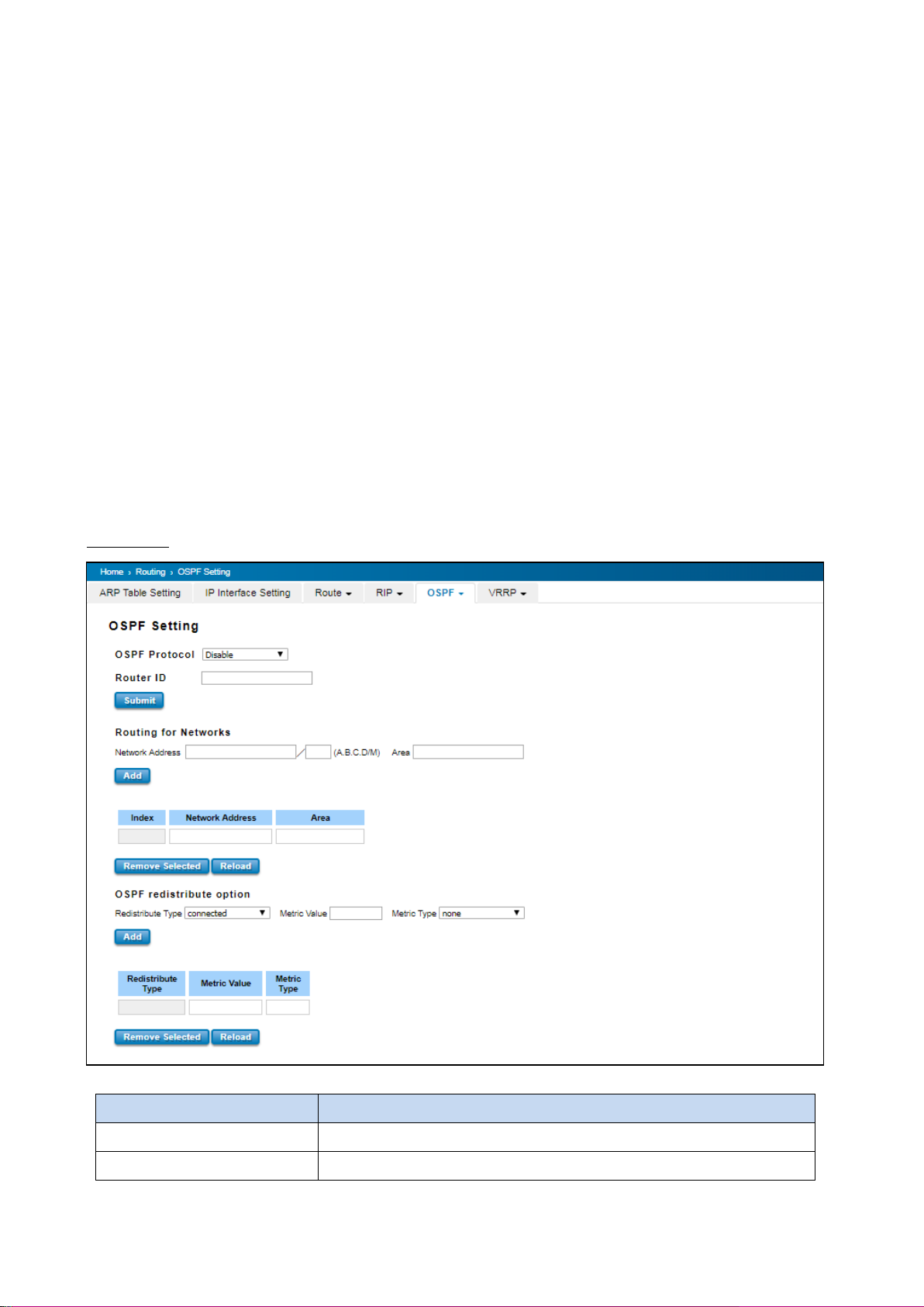
TERMS
DESCRIPTION
OSPF Protocol
Enable or Disable the OSFP routing protocol.
Router ID
The router ID can be any IP address, however, the IP address of the existed
3.8.5 OSPF
Open Shortest Path First is a link-state protocol that equips the IP, mask, the type of network, the routers connected
to that network. The State is its relationship to its neighboring routers. The Metric is the distance between the 2
links; it is usually the bandwidth of the link in link-state protocol. The Link State Database is the collection of all these
link states. The destination network address, the shortest metric to the network and the IP address of the next hop
are specified in the link state database.
The OSPF is a complex protocol which defines the role of the router/switch when it is installed in different Areas. The
Area is a group of routers, the OSPF uses flooding to exchange link-state updates between routers. The routers
within the same area update its routing table. Any change in routing information is flooded to all routers in the same
area.
WoMaster Layer3 Managed Switch design comforts to the OSPF Version 2 specification. Typically, the switch acts as
the Internal Router, a router within the area; the Designated Router, the Master router in the same broadcast
domain within the area; the Area Board Router which is the boundary router between different area. While
configuring the OSPF network, the area ID should be configured with the same IP address or the same area ID. The
0.0.0.0 is usually used.
OSPF Setting
82
Page 83
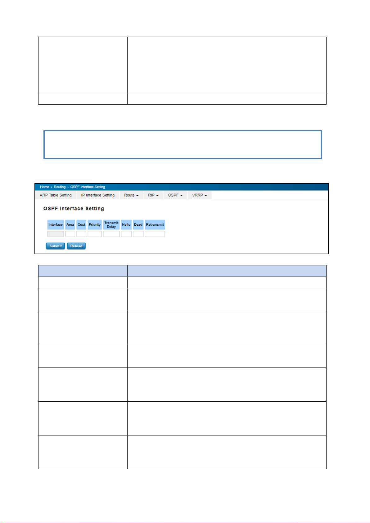
local interface is suggested. With such IP address, you can find the
router/switch easier.
Router ID is used while connected multiple OSPF routers/switches to the
same broadcast domain, the lowest Router ID will be selected as the
Designated Router in the network.
Routing for Network
Type the Network Address and the Area ID in the field.
TERMS
DESCRIPTION
Interface
The VLAN Interface name.
Area
The area ID of the Interface you added. The Area ID must be the same for all
routers/switches on a network.
Cost
The distance of this link/Interface, the default is identified depends on what
the bandwidth is by the system. The value can be changed to decide the
best router.
Priority
The priority of this link/Interface. Set priority to help find the OSPF
designated router for a network. The default is 1. The range is 0 to 255.
Transmit Delay
The transmit delay timer of this link/Interface. Transmit Delay is the
estimated number of seconds to wait before sending a link state update
packet. The default value is 1 second.
Hello
The Hello timer of this link/Interface. The value must be the same for all
routers/switches on a network. The default value is 10 seconds. The min.
value is 1.
Dead
The Dead Interval Timer of this link/Interface. The Dead timer is the time to
identify whether the interface is down or not before the neighbors declare
the OSPF router to be down. The default value is 4 times (40 seconds) than
NOTE: All the Area ID of the router/switch within the same area should use the same IP address or ID. All
the network address should be added.
Click Add to apply the setting then the new entry will appear in the network table below. Click the Remove Selected
button to remove the selected network. Click the Reload button to reload the table.
OSPF Interface Setting
83
Page 84
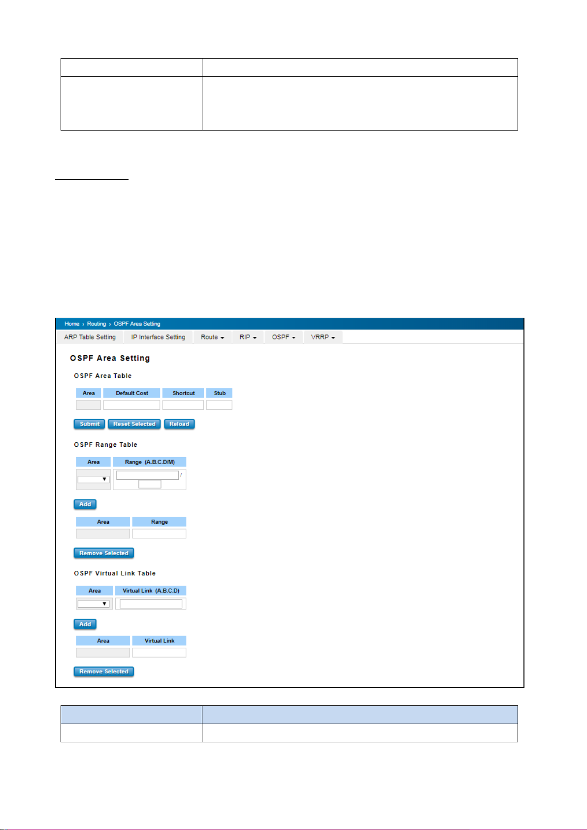
the Hello interval (default is 10).
Retransmit
The count of Retransmit of this link/Interface. The Retransmit time specifies
the number of seconds between link state advertisement transmissions.
The default value is 5 seconds.
TERMS
DESCRIPTION
Area
This field indicates the area ID. Select the ID you want to modify here.
Once finish configuring the settings, click on Apply to apply configuration.
OSPF Area Setting
This page allows user to configure the OSPF Area information.
An OSPF domain is divided into different areas. Areas are logical grouping of hosts and networks, including their
routers having interfaces connected to any of the included networks. Each area maintains its own link state database.
In OSPF, all areas must be connected to a backbone area. The backbone area is responsible for distributing routing
information between non-backbone areas. The WoMaster Switch is usually installed as internal router of a single
Area environment. While there are multiple areas in the network, this page allows modify the Area information and
Virtual Link.
84
Page 85
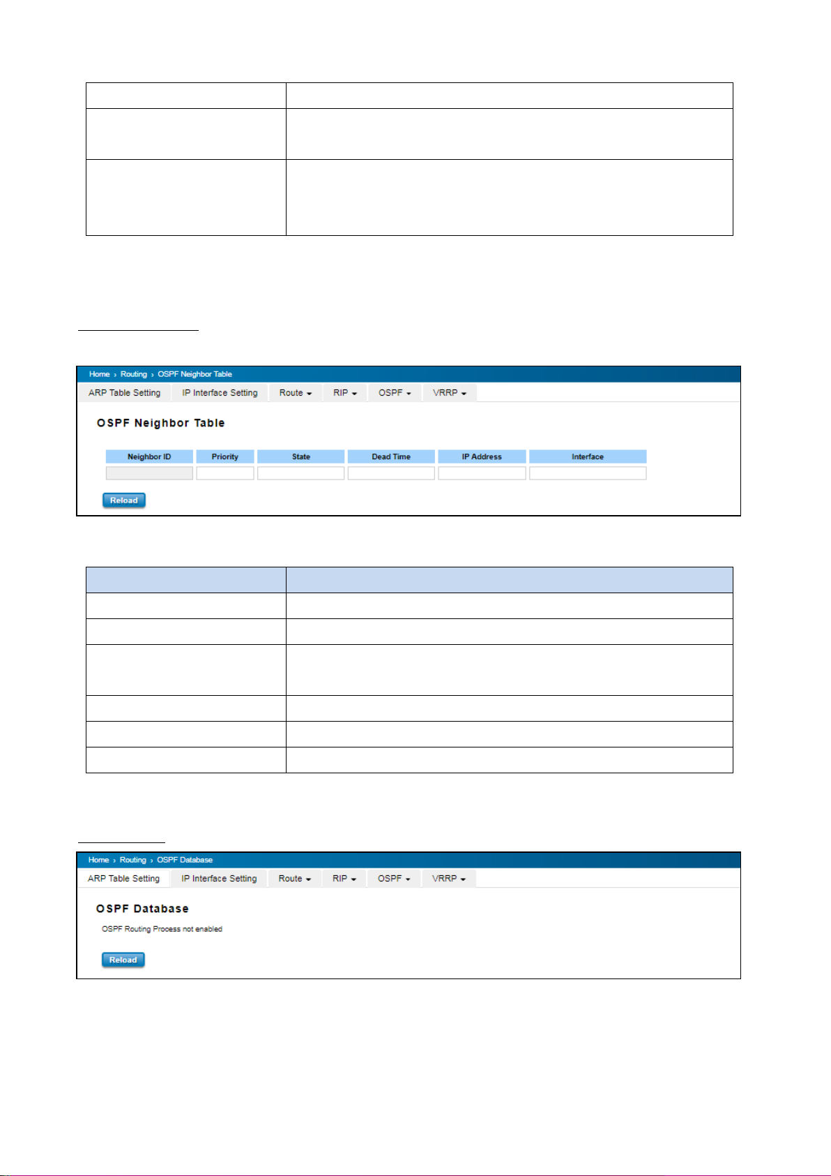
Default Cost
The default cost of the area ID.
Shortcut
No Defined, Disable, Enable. This indicates whether the area is the OSPF
ABR shortcut mode.
Stub
Represents whether the specified Area is a stub area or not. The possible
values are No Defined, No Summary and Summary. Summary is used to
advertise summary routes.
TERMS
DESCRIPTION
Neighbor ID
Display the Router ID of the Neighbor routers/switches.
Priority
Show the priority of the link.
State
While the State is changed to Full, which means the exchange progress is
done.
Dead Time
The activated time of the link.
IP Address
Shows the learnt IP interface of the next hops.
Interface
Shows the connected local interface.
Click the Apply button to apply OSPF area settings. Click the Remove Selected button to remove selected area.
Click the Reload button to reload OSPF area configurations.
OSPF Neighbor Table
This page allows user to see the OSPF Neighbor information. The Neighbor interface and its state will be listed here.
The Hello packets are exchanged between the switch to next switches.
Click Reload to update the information from the table.
OSPF Database
Click Reload to update the information.
85
Page 86
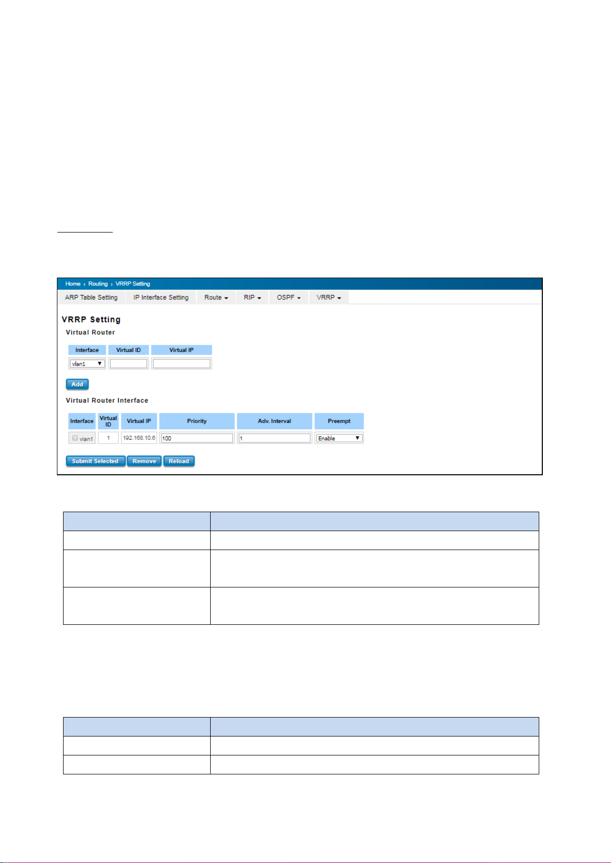
TERMS
DESCRIPTION
Interface
Select the interface for the VRRP domain.
VirtualID
This is a virtual ID range from 1~255. The switches within the same VRRP
domain should have the same Virtual ID.
Virtual IP
This is the virtual IP of the VRRP domain. This is the Gateway IP of the
clients.
TERMS
DESCRIPTION
Interface
Select the interface for the VRRP domain.
VirtualID
This is a virtual ID range from 1~255. The switches within the same VRRP
3.8.6 VRRP
The VRRP represent for the Virtual Router Redundancy Protocol. To further ensure the high reliability of an
environment, WoMaster switch supports the VRRP protocol allowing the hosts to continuously direct traffic to the
default gateway without the default gateway configuration change. The figure for example, there are 3 VRRP-aware
switches with the same Virtual IP of the VRRP, but different IP address of their VLAN/IP interface.
One is selected as the VRRP Master and the others are VRRP Backup. The client PCs has the same gateway IP which is
the virtual IP of the 3 switches. Once the VRRP Master switch or the VLAN interface failure, the VRRP Backup switch
will act as the new Master immediately, thus the communication from the client PC will not stop.
VRRP Setting
The fields allow you to create the Virtual Router Interface. All the layer 3 switches within the same VRRP domain
should be located within the same IP network and equips with the same Virtual ID and Virtual IP address.
Virtual Router
Click Add once finish the configuration. Then a new entry is created in the Virtual Router Interface Configuration
page. After the VRRP interface is created, user can see the new entry and adjust the settings to decide the policy of
the VRRP domain.
Virtual Router Interface
86
Page 87
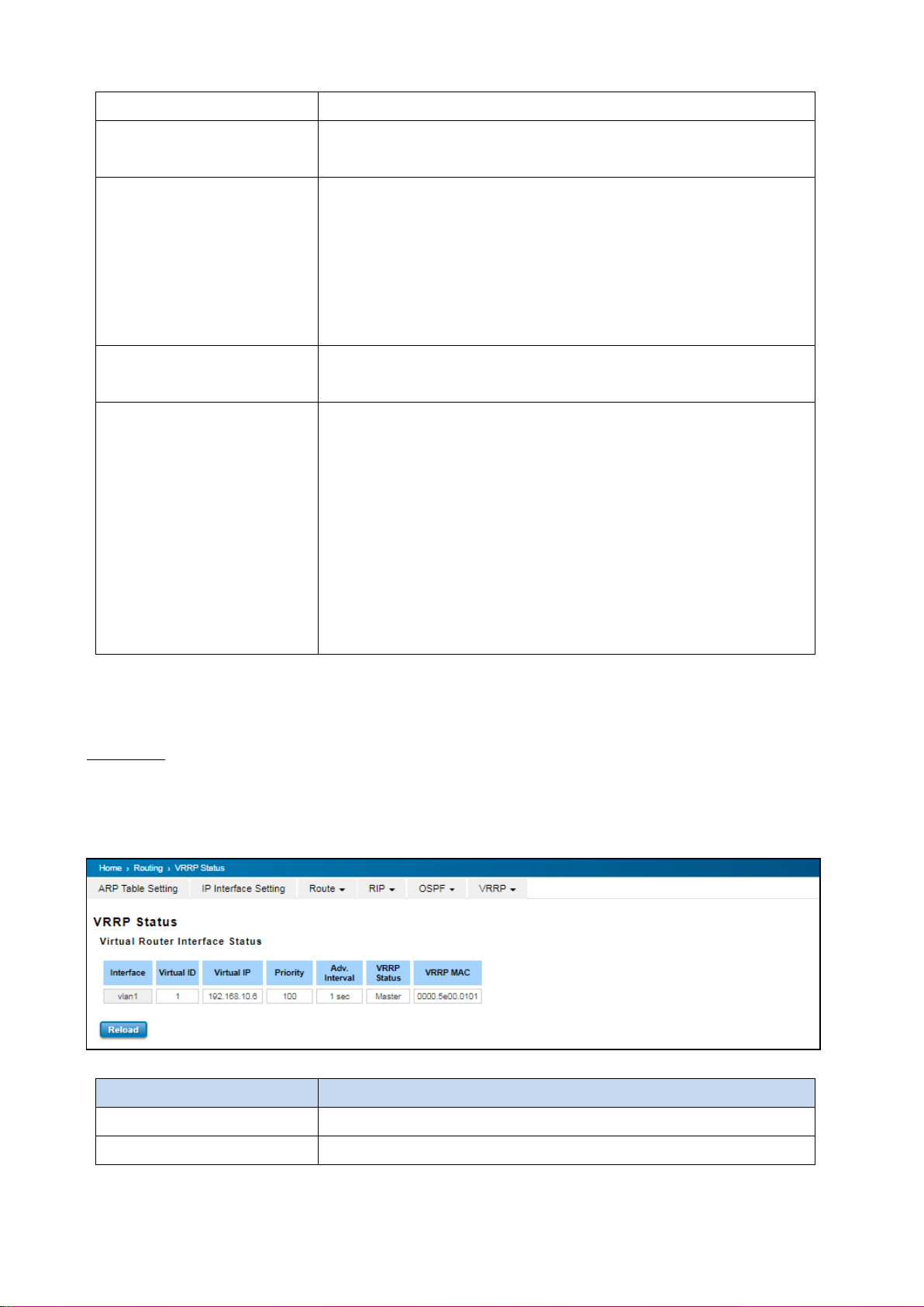
domain should have the same Virtual ID.
Virtual IP
This is the virtual IP of the VRRP domain. This is the Gateway IP of the
clients.
Priority
The priority of the entry of this switch. In VRRP domain, the VRRP switches
must have the same Virtual ID and Virtual IP settings and choose who
should be the VRRP Master switch. The switch equips with the highest
priority will be selected as the VRRP master. The priority setting field can be
manually changed, the range is from 1~254, 255 for virtual IP owner and
100 for backup by default.
Adv. Interval
This field indicates how often the VRRP switches exchange the VRRP
settings.
Preempt
While the VRRP Master link is failure, the VRRP Backup will take over its job
immediately. However, while the VRRP master link is recovered, who should
be the Master? The Preempt decide whether the VRRP master should be
recovered or not.
While the Preempt is Enable and the interface is VRRP Master, the interface
will be recovered.
While the Preempt is Disable and the interface is VRRP Master, there is no
change while the link is recovered. The VRRP backup acts as the Master
before restart the switches.
TERMS
DESCRIPTION
Interface
Select the interface for the VRRP domain.
VirtualID
This is a virtual ID range from 1~255. The switches within the same VRRP
Click the Submit Selected button to apply the configuration. Click the Remove Selected button to remove selected
setting. Click the Reload button to reload table.
VRRP Status
The VRRP represent for the Virtual Router Redundancy Protocol. To further ensure the high reliability of an
environment, the Layer 3 switch supports the VRRP protocol allowing the hosts to continuously direct traffic to the
default gateway without the default gateway configuration change.
87
Page 88

domain should have the same Virtual ID.
Virtual IP
This is the virtual IP of the VRRP domain. This is the Gateway IP of the
clients.
Priority
The priority of the entry of this switch. In VRRP domain, the VRRP switches
must have the same Virtual ID and Virtual IP settings and choose who
should be the VRRP Master switch. The switch equips with the highest
priority will be selected as the VRRP master. The priority setting field can be
manually changed, the range is from 1~254, 255 for virtual IP owner and
100 for backup by default.
Adv. Interval
This field indicates how often the VRRP switches exchange the VRRP
settings.
VRRP Status
While the VRRP Master link is failure, the VRRP Backup will take over its job
immediately
VRRP MAC
This field indicates the VRRP MAC in this configuration entry.
88
Page 89
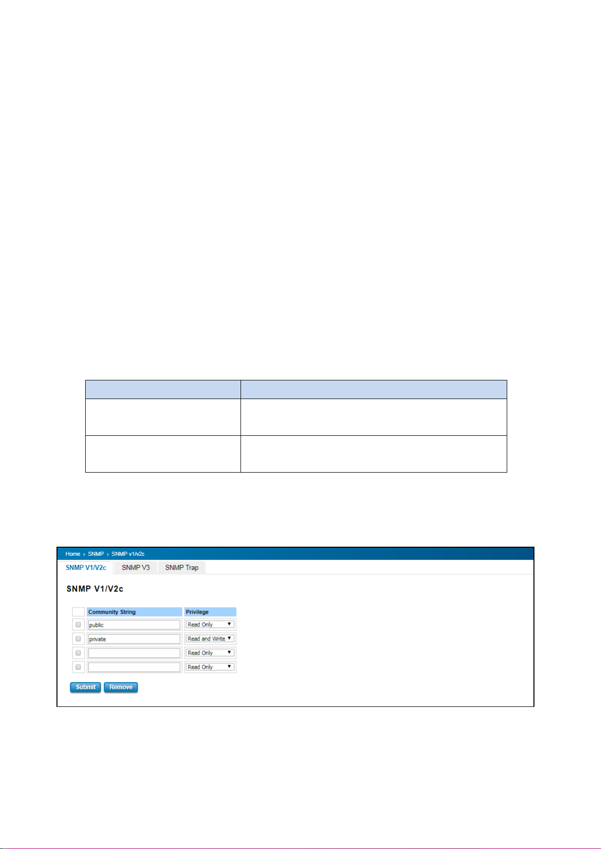
PRIVILEGE
DESCRIPTION
Read Only
User only has the ability to read the values of MIB tables.
Default community string is Public.
Read and Write
User has the ability to read and set the values of MIB tables.
Default community string is Private.
3.9 SNMP
SNMP is a standard TCP/IP protocol for network management. Network administrators use SNMP to monitor and
map network availability, performance, and error rates. System management software uses SNMP to allow
administrators to remotely monitor and manage thousands of systems on a network, often by presenting the data
gathered from monitored devices in a snapshot or dashboard view. WoMaster Managed Switch support SNMP v1
and v2c and V3.
SNMP managed network consists of two main components: agents and a manager. An agent is a management
software module that resides in a managed switch. An agent translates the local management information from the
managed device into a SNMP compatible format. The manager is the console through the network.
3.9.1 SNMP V1/V2c SETTING
In this page allows users to define the new community string set and remove the unwanted community string. The
community string can be viewed as the password because SNMP V1/V2c doesn’t request User to enter password
before User tries to access SNMP agent.
The community includes 2 privileges, Read Only and Read and Write.
WoMaster Managed Switch allows users to assign 4 community strings. Type the community string and select the
privilege. Then press Submit. When User first installs the device in User network, we highly recommend User to
change the community string. Since most SNMP management application uses Public and Private as their default
community name, this might be the leakage of the network security.
3.9.2 SNMP V3
SNMP v3 can provide more security functions when the user performs remote management through SNMP protocol.
89
Page 90
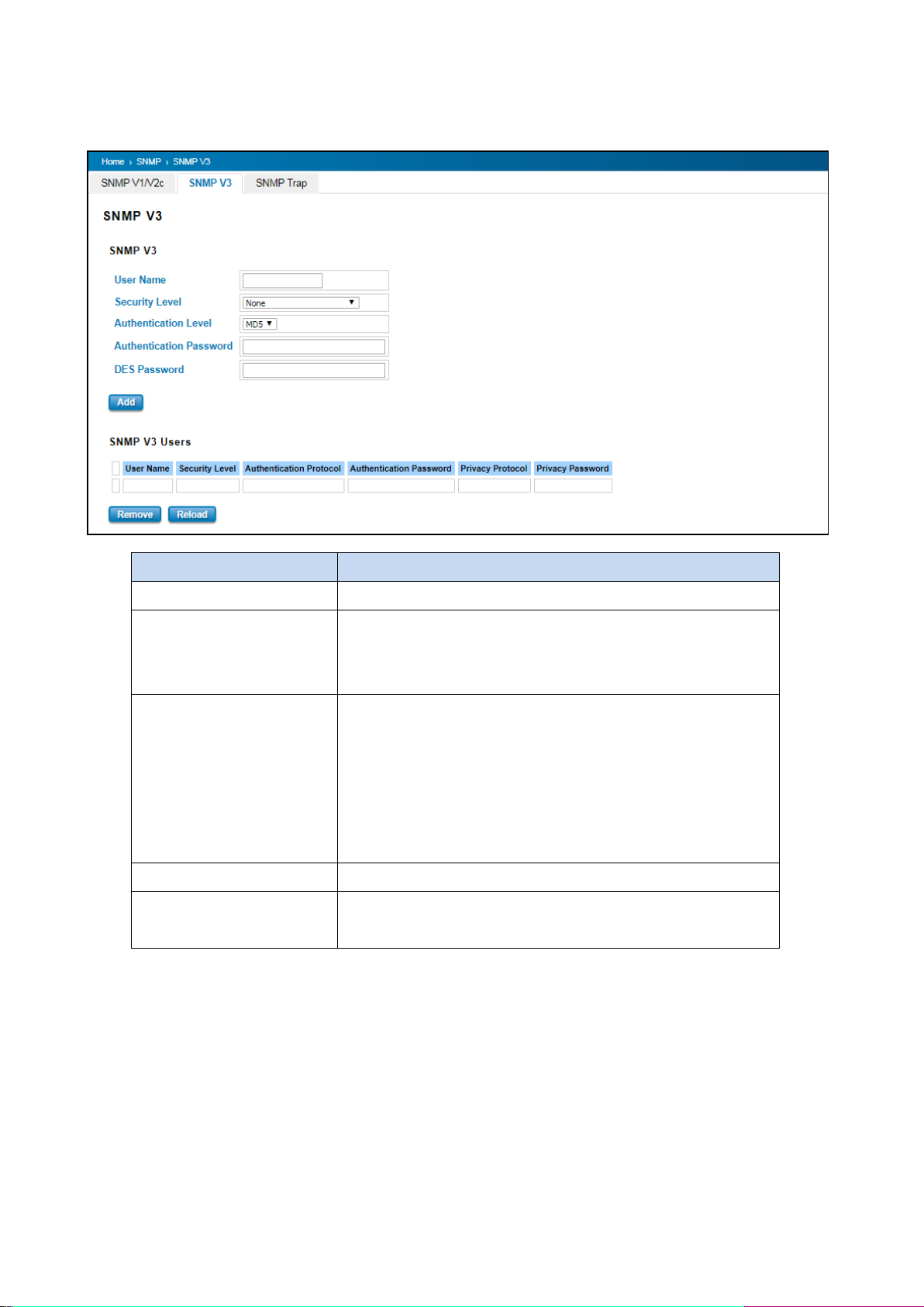
TERMS
DESCRIPTION
User Name
Set up the user name.
Security Level
Default: None
Here the user can select the following levels of security: None, User
Authentication, and Authentication with privacy.
Authentication Level
Default: MD5
MD5 (Message-Digest algorithm 5) is a widely used cryptographic
hash function with a 128-bit hash value. SHA (Secure Hash
Algorithm) hash functions refer to five Federal Information
Processing Standard-approved algorithms for computing a
condensed digital representation.
Authentication Password
Here the user enters the SNMP v3 user authentication password.
DES Password
Here the user enters the password for SNMP v3 user DES
Encryption.
It delivers SNMP information to the administrator with user authentication; all of data between the switch and the
administrator are encrypted to ensure secure communication.
3.9.3 SNMP TRAP
SNMP Trap is the notification feature defined by SNMP protocol. All the SNMP management applications can
understand such trap messages generated by the switch. If no trap manager is defined, no traps will be issued. To
define a management station as a trap manager, assign an IP address, enter the SNMP community strings, and select
the SNMP trap version. Below is the SNMP Trap Interface.
90
Page 91
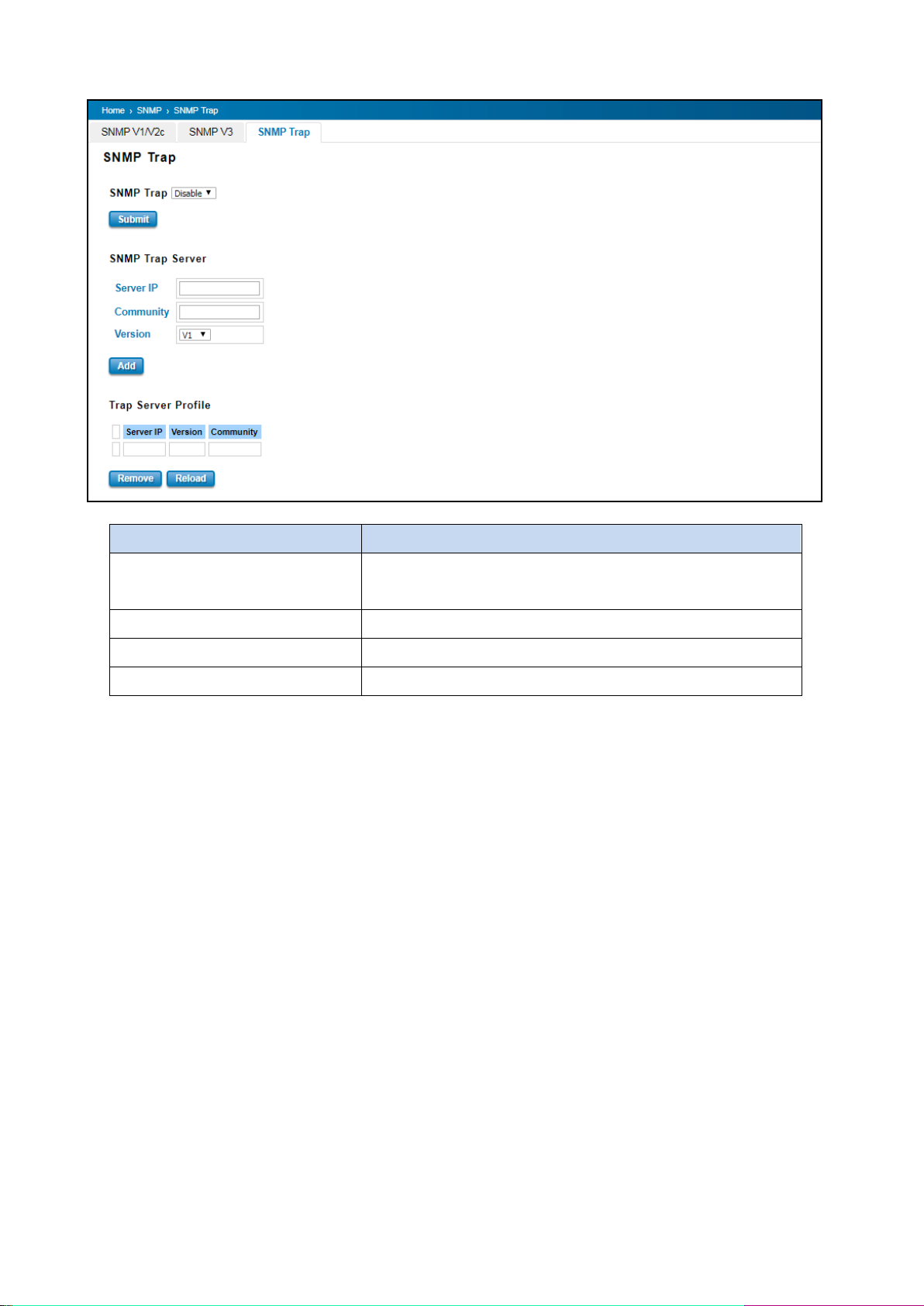
TERMS
DESCRIPTION
SNMP Trap
Default: Disable
Enable / Disable SNMP Trap
Server IP
Enter the IP address of the trap manager.
Community
Enter the community string for the trap station.
Version
Select the SNMP trap version type—v1 or v2c.
After configuration, Click Add then User can see the change of the SNMP pre-defined standard traps.
91
Page 92
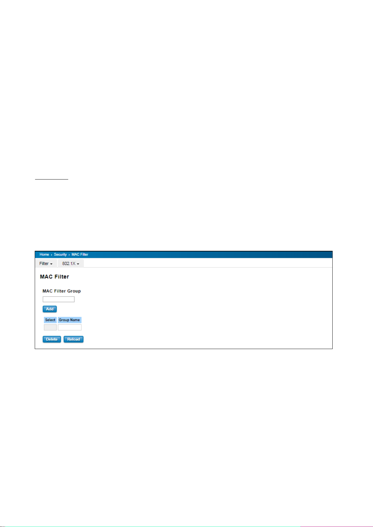
3.10 SECURITY
WoMaster Switch provides several security features for User to secure access to its management functions and it
can be remotely managed (monitored and configured).
Following topics are included in this section:
3.10.1 Filter
3.10.2 IEEE 802.1X
3.10.1 FILTER
Filter is known as Access Control List feature. There are 2 major types; one is MAC Filter that allows user to define
the access rule based on the MAC address flexibility. Another one is IP Filter. It includes the IP security, IP Standard
access list and advanced IP based access lists.
MAC Filter
Network security can be increased by limiting access on a specific port only to users with specific MAC addresses.
Mac Filter feature allows User to stop the MAC address learning for specific port. After stopping MAC learning, only
the MAC address listed in the list can access the switch and transmit/receive traffic. This is a simple way to secure
User network environment and not to be accessed by hackers.
MAC Filter Group
Create a group of MAC Filters by entering a name and clicking the Add button to create a new Filter Group. The MAC
Filter Group table provides the following information. Select the entry and click the Delete button then the Filter
Group is deleted. Click the Reload button to reload the MAC Filter Group table.
92
Page 93
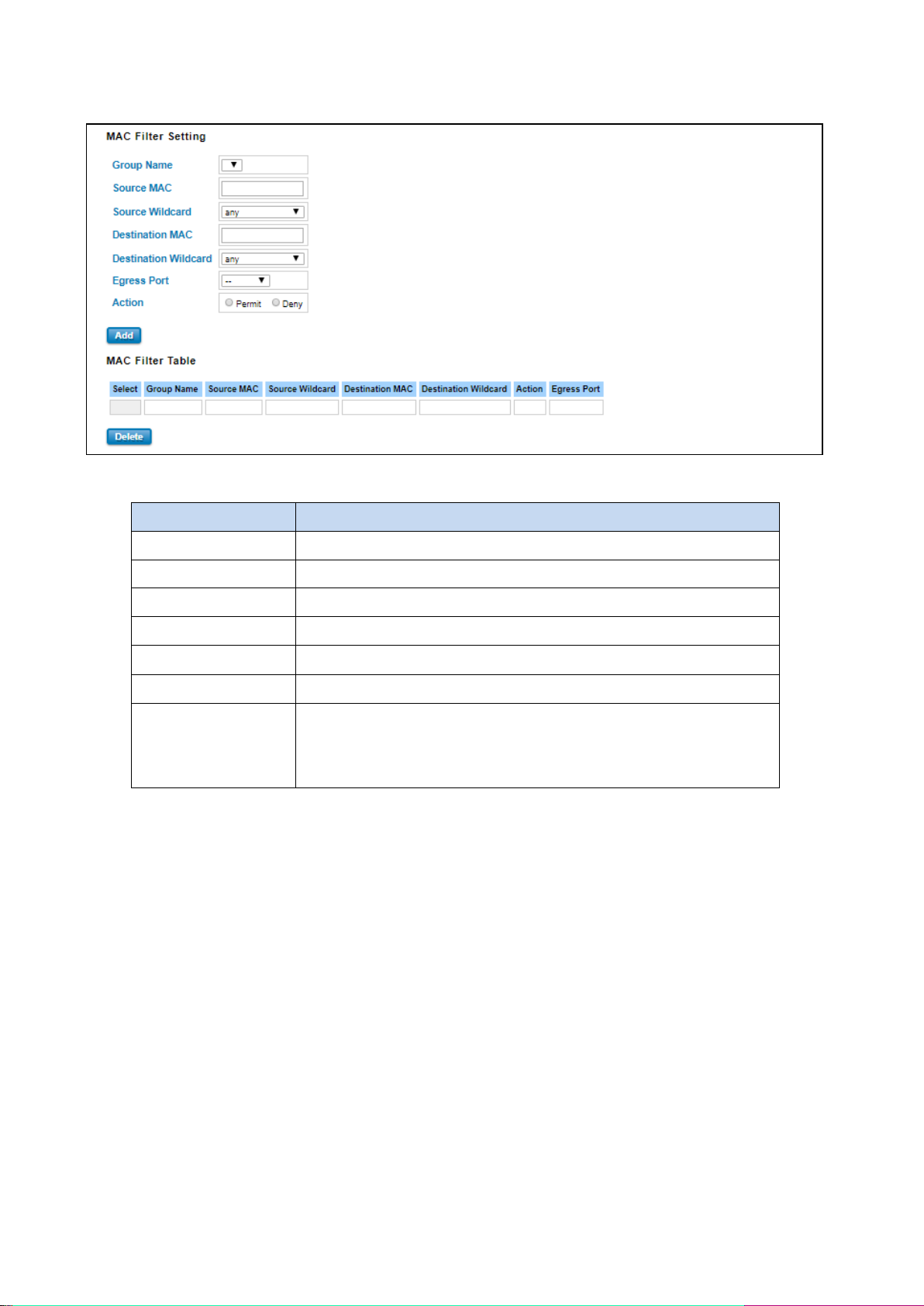
TERMS
DESCRIPTION
Group Name
This is the name of the MAC Filter Group.
Source MAC
This is the source MAC Address of the packet.
Source Wildcard
This is the mask of the MAC Address.
Destination MAC
This is the destination MAC Address of the packet.
Destination Wildcard
This is the mask of the MAC Address.
Egress Port
This is the outgoing (exiting) port number.
Action
This is the filter action, which is to deny or permit the packet.
Permit: to permit traffic from specified sources.
Deny: to deny traffic from those sources.
MAC Filter Setting
In this form user may configure the MAC Filter Setting. The description of the columns is as below:
Once User finishes configuring the settings, click on Submit/Add to apply User configuration.
93
Page 94
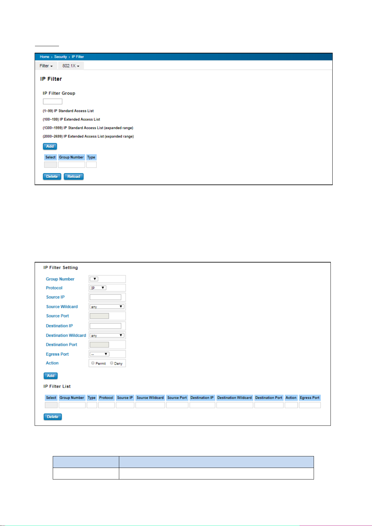
TERMS
DESCRIPTION
Group Number
Number of the Filter Group.
IP Filter
User can create a group of IP Filters with following numbers.
1 - 99: IP Standard Access List
100 – 199: IP Extended Access List
1300 – 1999: IP Standard Access List (expanded range)
2000 – 2699: IP Extended Access List (expanded range)
After entering the IP Filter Group number, click the Add to create the new Filter Group.
IP Filter Setting
94
Page 95
Protocol
This is the L4 protocol (IP/TCP/UDP/ICMP).
Source IP
This is the source IP address of the packet.
Source Wildcard
This is the mask of the IP address.
Source Port
This is the source port of L4 protocol (TCP/UDP)
Destination IP
This is the destination IP address of the packet.
Destination Wildcard
This is the mask of the IP address.
Destination Port
This is the destination port of L4 protocol (TCP/UDP).
Egress Port
This is the outgoing (exiting) port number.
Action
This is the filter action, which is to deny or permit the packet.
Permit: to permit traffic from specified sources.
Deny: to deny traffic from those sources.
TERMS
DESCRIPTION
Select
Selected the entry for delete.
Group Number
Number of the Filter Group.
Type
This is the filter group type (standard or extended).
Protocol
This is the L4 protocol (IP/TCP/UDP/ICMP).
Source IP
This is the source IP address of the packet.
Source Wildcard
This is the mask of the IP address.
Source Port
This is the source port of L4 protocol (TCP/UDP)
Destination IP
This is the destination IP address of the packet.
Destination Wildcard
This is the mask of the IP address.
Destination Port
This is the destination port of L4 protocol (TCP/UDP).
Action
This is the filter action, which is to deny or permit the packet. Click the
Delete button to remove the Filter that has been selected.
Egress Port
This is the outgoing (exiting) port number.
IP Filter List
95
Page 96
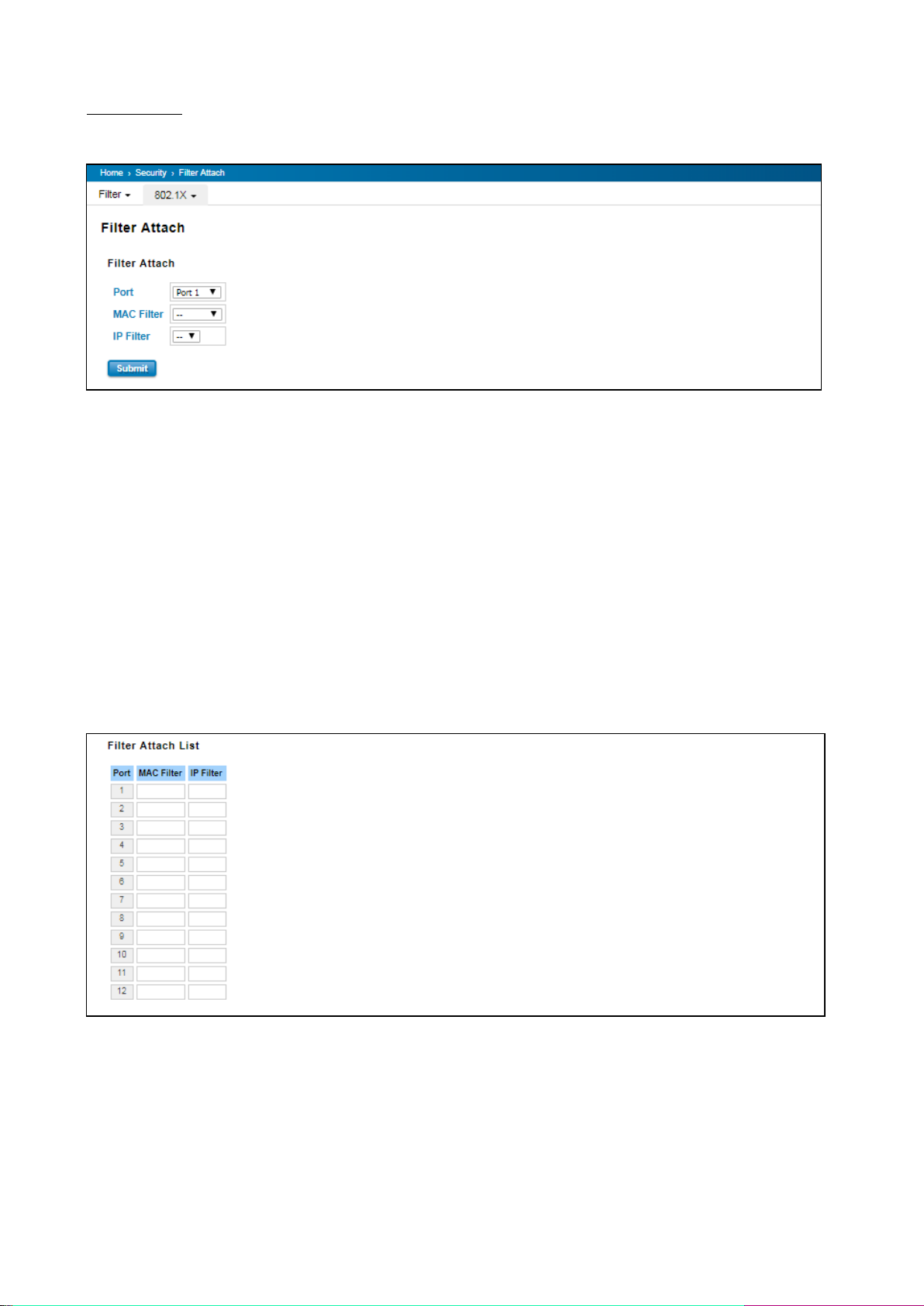
Filter Attach
This page allows you to attach filters created on the IP Filter and MAC Filter pages to ports on the switch.
Port: The port you want to attach a filter to.
MAC Filter: Select a MAC address based filter to attach to the interface. Select "--" to remove an
attached MAC address filter.
IP Filter: Select an IP address based filter to attach to the interface. Select "--" to remove an attached IP
address filter.
Click the Apply button to apply the configurations.
Filter Attach List
This table displays what filters are currently attached to each port.
Port: The port the filters are attached to.
MAC Filter: The MAC address filter attached to the port.
IP Filter: The IP address filter attached to the port.
96
Page 97
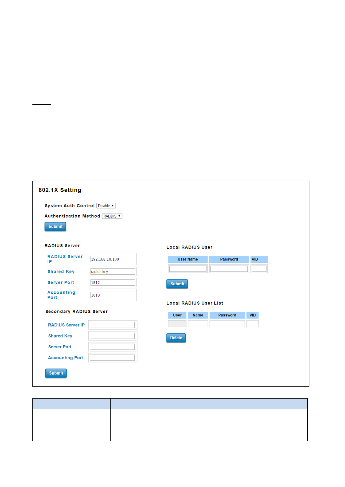
TERMS
DESCRIPTION
System Auth Control
To enable or disable the 802.1X authentication.
Authentication Method
Radius is a authentication server that provide key for authentication, with this
method, user must connect switch to server. If user selects Local for the
3.10.2 IEEE 802.1X
802.1X is an IEEE Standard for Port-based Network Access Control that provides an authentication mechanism to
devices that wish to attach to a LAN or WLAN. Port-based network access control protocol contains 3 parts,
supplicant, authenticator, and authentication server. W ith 802.1X authentication, a username can be linked with an
IP address, MAC address, and port. This provides greater visibility into the network. 802.1X also provides more
security because it only allows traffic transmitting on authenticated ports or MAC addresses.
RADIUS
RADIUS is used in the authentication process. Database of authorized users is maintained on a RADIUS server. There
is an authenticator, our switch enabling 802.1X, to forward the authentication requests between authentication
(RADIUS) server and client. Allowing or denying the requests decides if the client can connect to a LAN/WAN or not.
802.1X Setting
IEEE 802.1X is the protocol that performing authentication to obtain access to IEEE 802 LANs. It is port-base network
access control. With the function, WoMaster switch could control which connection is available or not.
The description of the columns is as below:
97
Page 98
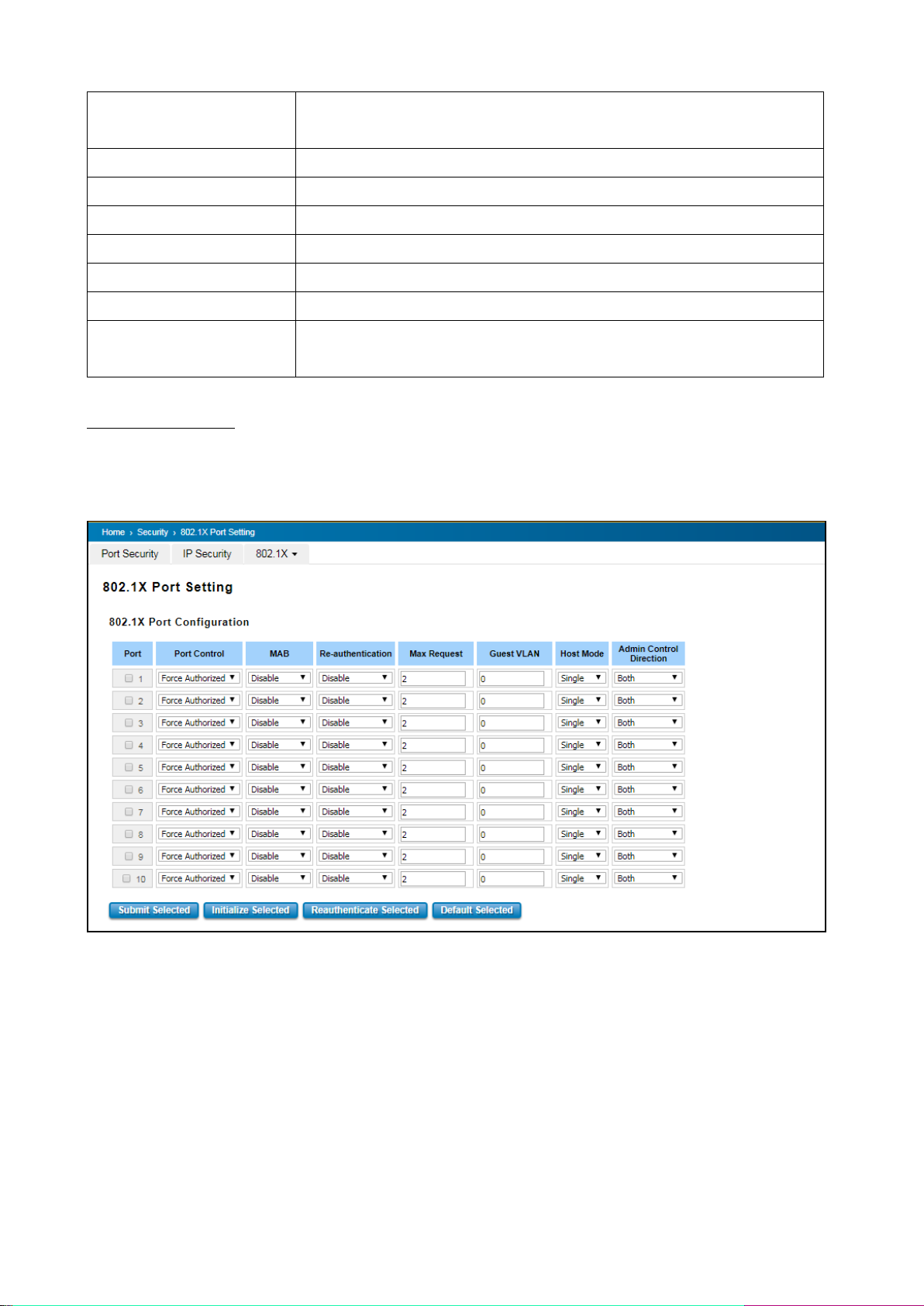
authentication method, switch use the local user data base which can be created
in this page for authentication.
Radius Server IP
The IP address of Radius server
Shared Key
It is the password for communicate between switch and Radius Server.
Server Port
UDP port of Radius server.
Accounting Port
Port for packets that contain the information of account login or logout.
Secondary Radius Server IP
Secondary Radius Server could be set in case of the primary radius server down.
802.1X Local User
Here User can add Account/Password for local authentication.
802.1X Local User List
This is a list shows the account information; User also can remove selected
account.
802.1X Port Setting
After the configuration of Radius Server or Local user list, user also need configure the authentication mode,
authentication behavior, applied VLAN for each port and permitted communication. The following information will
explain the port configuration.
98
Page 99
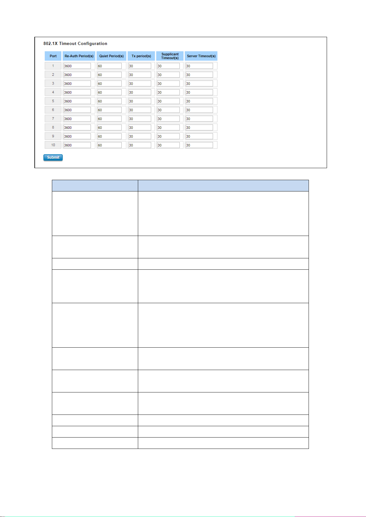
TERMS
DESCRIPTION
Port control
Force Authorized means this port is authorized; the data is free
to in/out. Force unauthorized just opposite, the port is blocked. If
users want to control this port with Radius Server, please select
Auto for port control.
Re-authentication
Default: 3600 seconds
If enable this field, switch will ask client to re-authenticate.
Max Request
The maximum times that the switch allow client request.
Guest VLAN
0 to 4094 is available for this field. If this field is set to 0, that
means the port is blocked after authentication fail. Otherwise,
the port will be set to Guest VLAN.
Host Mode
If there are more than one device connected to this port, set the
Host Mode to single means only the first PC authenticate success
can access this port. If this port is set to multi, all the devices can
access this port once any one of them pass the authentication.
Control Direction
Determined devices can end data out only or both send and
receive.
Re-Auth Period
Control the Re-authentication time interval, 1~65535 are
available.
Quiet Period
When authentication failed, Switch will wait for a period and try
to communicate with radius server again.
Tx period
The time interval of authentication request.
Supplicant Timeout
The timeout for the client authenticating
Sever Timeout
The timeout for server response for authenticating.
The description of the columns is as below:
Once User finishes configuring the settings, click on Submit to apply User configuration.
Click Initialize Selected to set the authorize state of selected port to initialize status.
99
Page 100
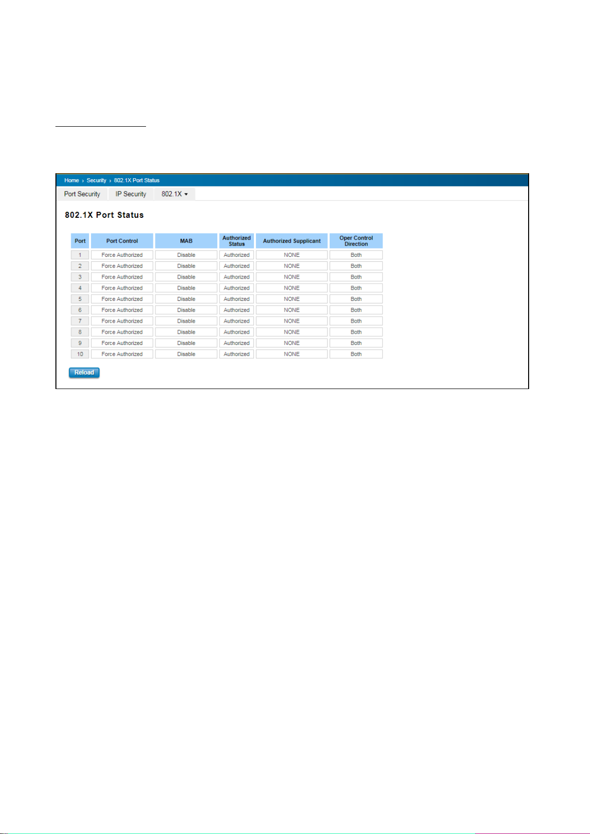
Click Re-authenticate Selected to send EAP Request to supplicant to request re-authentication.
Click Default Selected to reset the configurable 802.1X parameters of selected port to the default values.
802.1X Port Status
User can observe the port status for Port control, Authorized Status, Authorized Supplicant and Open Control
Direction from each port.
100
 Loading...