

Wolo BAS-100 User Manual
INSTALLATION INSTRUCTIONS
Model BAS-100 Back-Up Alarm
Activation Switch
Your choice of a Wolo activation switch is a perfect choice to control your vehicle’s back-up alarm system.
Wolo’s products are manufactured with the best quality materials that are carefully inspected and tested before
being packaged. Precision workmanship and quality components will assure years of dependable service. If you
need help installing your Wolo product, or have any questions, our technicians are available to answer your
questions, Monday through Friday from 9 AM to 4 PM EST at 1-888-550-HORN (4676).
Before installation is attempted, it is important to read these instructions completely. The lives of people are
dependent on a proper installation of the activation switch to operate the back-up alert system. The person doing
the installation must have advanced knowledge of the proper method for mounting, securing the activation
switch and the electrical system wiring of the vehicle. Again, read these instructions completely and note any
messages marked “IMPORTANT” or “WARNING’’. A safe installation will prevent serious injury or dam-
age to the vehicle.
The Model BAS-100 is designed for commercial vehicles that are not equipped with a back-up light system.
IMPORTANT: When determining the mounting location for the Model BAS-100 activation switch, ensure the
mounting location provides proper function without interfering with the vehicle’s operation, moving parts and the
operator and passengers’ safety.
IMPORTANT: Before working under the vehicle make sure the wheels are
CHOCKED to prevent the vehicle from moving.
1. Select the mounting location for the bracket and switch next to the linkage that
engages the vehicle into reverse. IMPORTANT: The coiled spring actuator
extension arm needs to be positioned so that end will be moved a minimum of
one inch (1”) when the linkage is positioned into reverse.
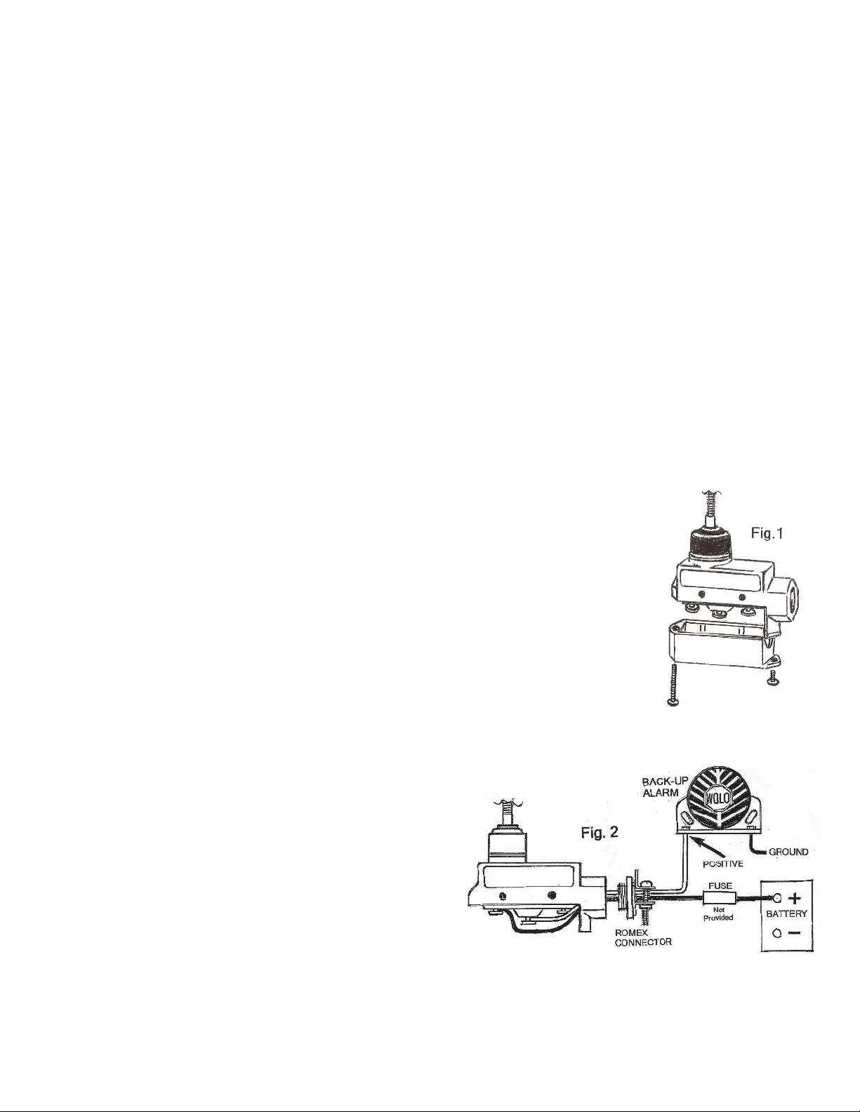
2. Remove the two Phillips head screws that secure cover to the switch’s housing.
When the cover is removed, you will have access to the internal micro switch. See
Fig. 1
3. Install the provided 3/8” Romex wire strain connector to the switch housing.
Wires that will be connected to the micro switch, will be routed through the
Romex connector. See Fig. 2.
4. Connect a wire, 16 gauge or heavier, to the back-up alarms positive wire or terminal. The other end of the
wire is connected to the actuator’s micro switch center
screw post, which is marked NORMALLY OPEN. See
Fig. 2.
5. Connect a wire, 16 gauge or heavier to the actuator’s
micro switch screw post marked COMMON. The other
end of the wire is connected to a positive power source.
WARNING: Protect the vehicle by installing an inline
fuse at the power source. Refer to the back-up alarm’s
specification sheet for the recommend fuse amperage.
Inline fuse holder not included. DO NOT INSTALL
THE FUSE INTO THE FUSE HOLDER UNTIL THE
INSTALLATION IS COMPLETE. See Fig.2.
6. Tighten the two screws of the Romex connector to secure wires.
7. The cover removed in step 2, is placed back onto the housing and secured.
8. Attach the mounting bracket to switch housing using the hardware provided. If the internal switch does not
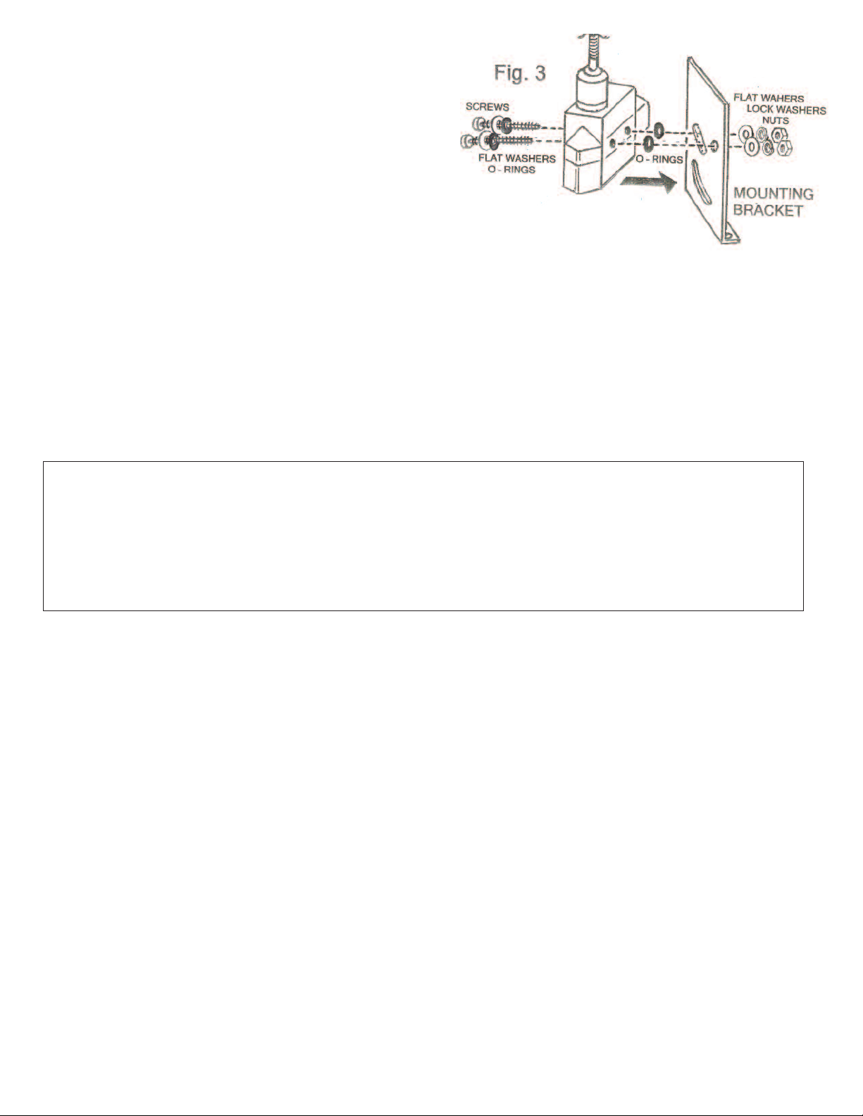
align with the two mounting holes, use a thin pointed
punch to align the holes in the switch with the housing.
IMPORTANT: Make sure that the O-rings are installed as
shown to ensure a watertight installation. See Fig. 3.
9. Secure the switch an mounting bracket to the vehicle.
10. Install the fuse into the fuse holder.
11. Test the back-up alarm system to ensure proper operation
before vehicle is placed into service.
WARRANTY
Wolo Manufacturing Corporation (“Wolo”) warranties to the original purchaser, for three months from the date of purchase, that this product is free from defects in workmanship and materials. If there is such a proven defect, Wolo, at
its option, will either repair or replace the item free of charge, if it is returned to Wolo within three months from the
date of purchase together with proof of purchase as described below. Wolo reserves the right to inspect any defect
prior to settling any warranty claim by repair or replacement. This warranty is limited as above provided and Wolo will
not be responsible for fire or other casualty or accident, due to neglect, abuse, abnormal use, modifications, faulty
installation of this product, or natural causes.
ANY EXPRESSED WARRANTY NOT PROVIDED HEREIN IS EXCLUDED AND DISCLAIMED. THE IMPLIED WARRANTIES OF MERCHANTABILITY AND OF FITNESS FOR A PARTICULAR PURPOSE ARE EXPRESSLY LIMITED TO
A TERM OF THREE (3) MONTHS. UNDER NO CIRCUMSTANCES SHALL WOLO BE LIABLE TO PURCHASER OR ANY
OTHER PERSON FOR ANY SPECIAL OR CONSEQUENTIAL DAMAGES, WHETHER ARISING OUT OF BREACH OF
WARRANTY OR OTHERWISE.
To obtain warranty service, return the product prepaid, and include the original bill of sale showing the date of purchase.
Provide with the return a brief description of the problem. Also, include with the return a check or money order in the
amount of $10.00 to cover return shipping. Mail to:
Wolo Manufacturing Corp.
One Saxwood Street, Deer Park, NY 11729
Attn: Warranty Service
E-mail: tech@wolo-mfg.com
© 2012 Wolo Mfg. Corp. All Rights Reserved
 Loading...