

Wolo 815 User Manual
Your purchase of a Wolo’s Challenger Horn System is a perfect choice to
compliment your vehicle. Wolo’s products are manufactured with the finest
materials. Each horn is tested to insure it meets all manufacturing specification,
before it is packaged. If you need help installing your new Wolo horn, our
technicians are available to answer your questions, Monday through Friday from
9 AM to 4 PM EST by calling 1-888-550-HORN (4676).
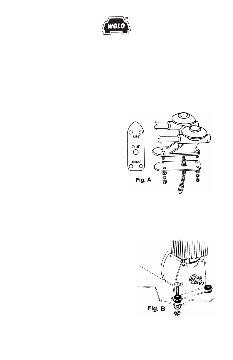
HORN INSTALLATION (Fig. A)
1. Locate the desired area you wish to
mount the dual trumpet air horn. For best
results, the front of the horn should be
unobstructed so that the sound can carry
straight ahead.
2. Use the horn’s rubber gasket as a
template, mark hole locations and drill to
sizes as shown in Fig. A.
3. Secure the horn with the hardware
provided. Tighten screws evenly to
provide a good watertight seal..
4. Secure the flexible inlet hose into the
base of the horn base. Do not remove
the Teflon tape on the threaded end of the hose. The tape is used to help
prevent air leaks.
CAUTION: Avoid making any kinks or sharp bends in
flexible hose that will reduce airflow and alter the horn’s sound.
COMPRESSOR INSTALLATION (Fig. B)
5. Locate an area in the engine compartment
that is dry and safe from the heat of the
exhaust manifold heat. Try to mount
compressor as far to the front of vehicle as
possible to provide a good airflow around
compressor.
IMPORTANT! Do not mount on fender well
or other flexible material.
6. Using the compressors mounting brackets
as a template, mark the hole locations and
drill to size. 15/64’’. Secure the compressor
to the mounting surface with the hardware
provided.
INSTALLATION INSTRUCTIONS
For Model 815
CHALLENGER LV
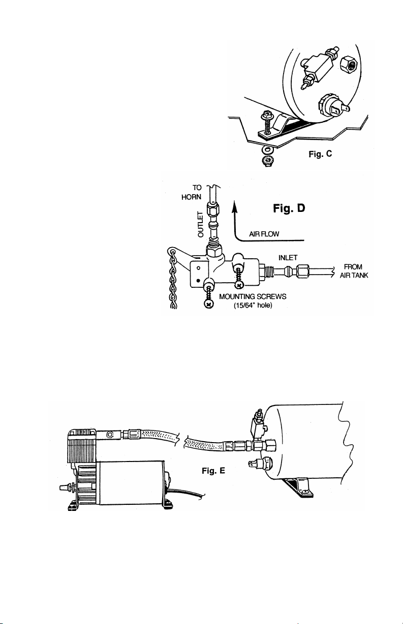
TANK INSTALLATION (Fig. C)
7. Locate a convenient area in the vehicle to
mount the air storage tank.
IMPORTANT!
When selecting a mounting location for the
tank, make sure that the compressor metal
braided hose is close enough to connect to
the tanks brass female fitting.
8. Use the tanks mounting bracket as a
template, mark the hole locations and drill
to size 15/64”. Secure tank with hardware
provided using the rubber gasket to
prevent vibration noise.
LANYARD VALVE
INSTALLATION (Fig. D)
9. Mount the lanyard valve
with the screws provided
in a convenient location
so that the chain can be
easily reached. Using the
lanyard valve as a
template, mark hole
locations and drill to size
5/16”.
IMPORTANT:
When connecting the air
hose to the lanyard valve,
they must be connected
only as shown in Fig. D.
HOSE INSTALLATION (Fig. E)
10. Connect the metal braided hose from the compressor to the tanks female
brass fitting.
11. Using the 1/4” plastic high pressure hose provided, cut to size to connect
the horn’s flexible inlet hose to the lanyard’s outlet fitting.
12. Unscrew the brass-fitting nut from the flexible inlet hose. Place the brassfitting nut onto the hose. Push the hose onto the male fitting of the flexible
hose and tighten the brass nut.
CAUTION: Do not over tighten nut.
13. Connect the other end of the hose to the outlet fitting of the lanyard’s valve.
Follow the same procedure as above number 12.
14. Using the 1/4” plastic high pressure hose provided, cut to size so to connect
the lanyard valves inlet fitting to the tank. Follow the same procedure as
above number 12 to connect hose to the lanyard and tank.
 Loading...