

Wolo 160 User Manual
INSTALLATION INSTRUCTIONS
Model 160-24 OCEAN ALERT MINI ™
24-Volt
Your purchase of a Wolo OCEAN ALERT™ Air Horn will complement your boat while offering an extra
level of protection. Wolo’s products are manufactured with the finest materials. Each horn is tested to ensure
it meets all of our manufacturing specifications, before being packaged. If you need help installing your new
Wolo horn, our technicians are available to answer your questions, Monday thru Friday, 9 AM to 4 PM EST
at 1-888-550-HORN (4676).
Before installation of the horn is attempted, it is important to read these instructions completely. The lives of
people can be dependent on a proper installation of the horn. The person doing the installation must have
knowledge of the proper method for mounting and securing the horn to the exterior of the boat as well as
knowledge of the boat’s electrical system. Again, read the instructions completely and note any messages
marked “IMPORTANT” or “WARNING’’. A safe installation will prevent injury or damage to the boat.
WARNING: Installation of the OCEAN ALERT requires drilling. The installer must carefully inspect both sides
of the selected mounting locations to ensure that there are no wires, fuel line and or any other components that
could be damaged by drilling.
WARNING: If any wires are routed through drilled holes; always de-burr ensuring that there are no sharp
edges. Install a rubber grommet into all metal holes that wires are being routed through.
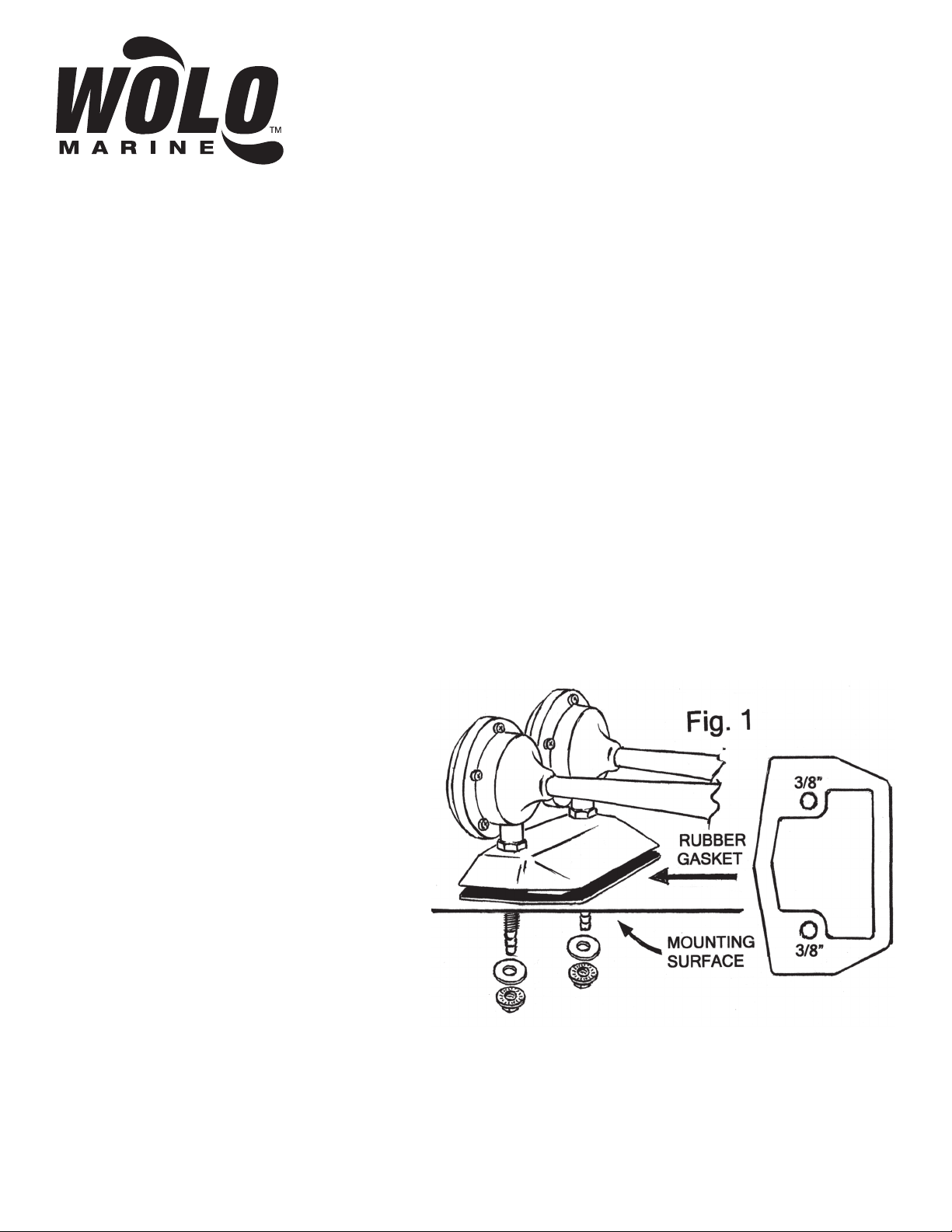
MOUNTING TRUMPET: Fig. 1
IMPORTANT: The horn should be mounted
facing forward whenever possible. The NMMA
Certification Program requires this for boats 39’
or longer.
1. Locate the desired mounting location of the
trumpet. For best results, the front of the horn
should be unobstructed so that the sound can
carry straight ahead.
IMPORTANT: FOR BEST PERFORMANCE
AND SOUND, ALWAYS MOUNT THE
COMPRESSOR CLOSE TO TRUMPET,
KEEPING THE HOSE LENGTH AS SHORT
AS POSSIBLE. THE COMPRESSOR
MUST BE MOUNTED IN A DRY INTERIOR
LOCATION).
air
inlet
tubes
2. Use the horn’s gasket as a template, mark
hole locations and drill to size.
3. Thread the two chrome air inlet tubes into the base of the horn.
4. Mount and secure the horn as shown in Fig. 1.
IMPORTANT: Be sure to use the rubber gasket provided to protect against water leaks. Tighten the base plate
nuts that thread onto air inlet tubes evenly to ensure a watertight seal.
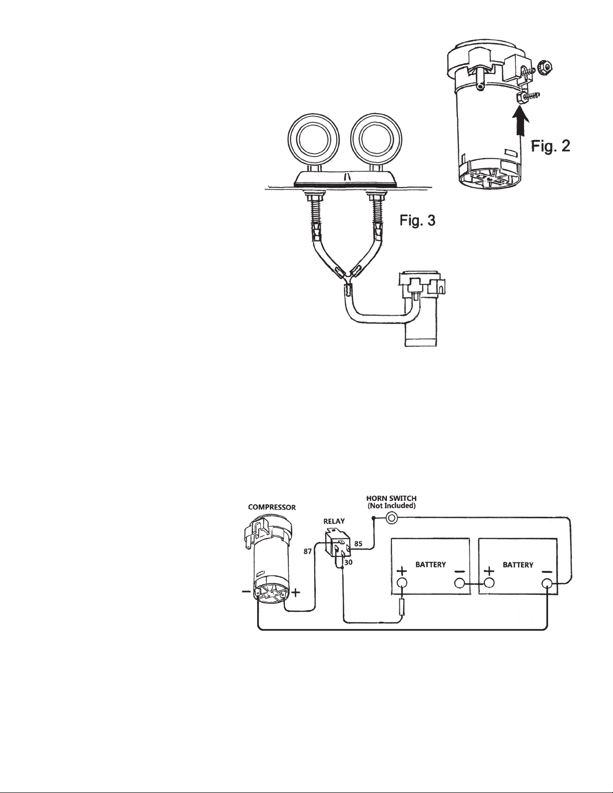
COMPRESSOR INSTALLATION: Fig. 2 & 3
5. Install the compressor in a dry interior location.
IMPORTANT: The compressor should not be mounted further than 30 inches
from the trumpet to ensure best sound.
6. To secure the compressor, drill one
3/16” hole. When possible, mount the
compressor vertically (air outlet on top).
Install the head of the bolt into the slot
on the side of the compressor. Secure
the compressor using the lock washer/
nut provided as shown in Fig. 2.
7. Using the plastic tubing provided, cut
to size and connect the compressor to
the horn’s two air inlets using the “Y”
air
inlet
tubes
connector provided as shown in Fig. 3.
WARNING: Avoid making any kinks
or sharp bends in plastic tubing that
can reduce air flow and alter the horn’s
sound. For best performance and sound
always keep the plastic tubing as short
as possible
WIRING:
ELECTRICAL CONNECTIONS FOR USING A NEW HORN BUTTON SWITCH Fig. 4
8. Install the horn relay provided, locate close to the compressor in a dry interior location with the terminals
facing downward.
9. Connect relay terminal 87 to the compressor’s positive (+) terminal. Use 16-gauge wire or heavier.
10. Connect relay terminal 85 to the horn button switch terminal. (Horn switch not provided).
11. The horn switch’s other terminal
is connected to negative (-) such as
the (-) battery post or any clean metal
Fig. 4
negative surface. Use 18 gauge wire or
heavier.
12. Connect relay terminal 30 &
86 to positive (+) 24-volts such as
battery, alternator, fuse block or
etc., using 16-gauge wire or heavier.
86
IMPORTANT: Protect the electrical
circuit with the fifteen (15)-amp inline
fuse provided. WARNING: The inline
fuse must be connected directly to the
15 AMP
FUSE
power source.
13. Connect the compressor’s negative
(-) terminal to boat’s battery, (-) post or
any clean metal negative surface. Use not less than 16-gauge wire.
RECAP OF RELAY TERMINAL CONNECTIONS:
Relay terminals 30 & 86: the two terminals are connected to 24-volts (+) positive, using the 15-amp inline fuse.
Relay terminal 85: is connected to horn switch.
The horn switch’s other terminal: is connected to negative (-) battery post.
Relay terminal 87: is connected to the compressor’s (+) motor terminal.
The compressor’s negative (-) terminal is connected the boat’s negative (-) battery post.
 Loading...