

Page 1
User Manual
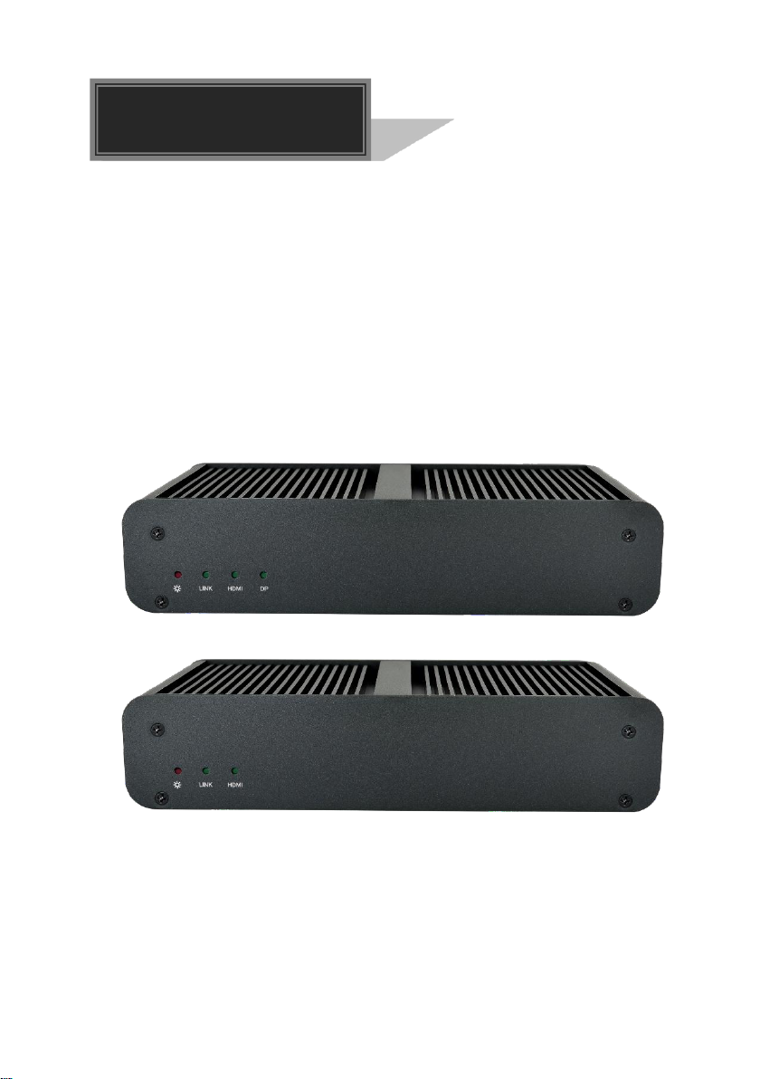
4K IP Streaming Extender
All Rights Reserved
Version: HDTVIPA100_2019V1.0
Page 2

4K IP Streaming Extender
Preface
Read this user manual carefully before using the product. Pictures shown in this
manual are for reference only. Different models and specifications are subject to real
product.
This manual is only for operation instruction, please contact the local distributor for
maintenance assistance. The functions described in this version were updated till
November, 2018. In the constant effort to improve the product, we reserve the right to
make functions or parameters changes without notice or obligation. Please refer to the
dealers for the latest details.
FCC Statement
This equipment generates, uses and can radiate radio frequency energy and, if not
installed and used in accordance with the instructions, may cause harmful interference
to radio communications. It has been tested and found to comply with the limits for a
Class A digital device, pursuant to part 15 of the FCC Rules. These limits are designed
to provide reasonable protection against harmful interference in a commercial
installation.
Operation of this equipment in a residential area is likely to cause interference, in which
case the user at their own expense will be required to take whatever measures may be
necessary to correct the interference.
Any changes or modifications not expressly approved by the manufacture would void
the user’s authority to operate the equipment.
Page 3

4K IP Streaming Extender
SAFETY PRECAUTIONS
To ensure the best performance from the product, please read all instructions carefully
before using the device. Save this manual for further reference.
Unpack the equipment carefully and save the original box and packing material for
possible future shipment.
Follow basic safety precautions to reduce the risk of fire, electrical shock and injury
to persons.
Do not dismantle the housing or modify the module. It may result in electrical shock
or burn.
Using supplies or parts not meeting the products’ specifications may cause
damage, deterioration or malfunction.
Refer all servicing to qualified service personnel.
To prevent fire or shock hazard, do not expose the unit to rain, moisture or install
this product near water.
Do not put any heavy items on the extension cable in case of extrusion.
Do not remove the housing of the device as opening or removing housing may
expose you to dangerous voltage or other hazards.
Install the device in a place with fine ventilation to avoid damage caused by
overheat.
Keep the module away from liquids.
Spillage into the housing may result in fire, electrical shock, or equipment damage.
If an object or liquid falls or spills on to the housing, unplug the module immediately.
Do not twist or pull by force ends of the optical cable. It can cause malfunction.
Do not use liquid or aerosol cleaners to clean this unit. Always unplug the power to
the device before cleaning.
Unplug the power cord when left unused for a long period of time.
Information on disposal for scrapped devices: do not burn or mix with general
household waste, please treat them as normal electrical wastes.
Page 4

4K IP Streaming Extender
Table of Content
1. Product Introduction .................................................................................................... 1
1.1 About 10G Network ........................................................................................... 1
1.2 Features ............................................................................................................ 2
1.3 Package List ...................................................................................................... 2
2. Specification ............................................................................................................... 4
3. Panel Description ........................................................................................................ 5
3.1 HDTVIPA100-TX Front Panel ............................................................................5
3.2 HDTVIPA100-TX Rear Panel.............................................................................5
3.3 HDTVIPA100-RX Front Panel.............................................................................6
3.4 HDTVIPA100-RX Rear Panel ............................................................................7
4. System Connection ..................................................................................................... 8
4.1 Usage Precaution .............................................................................................. 8
4.2 Connection Type ................................................................................................ 8
4.3 System Diagram ................................................................................................ 9
4.4 Hardware Setup ............................................................................................... 10
5. GUI Control ............................................................................................................... 12
5.1 Basic Configuration ......................................................................................... 12
5.2 Device Configuration ....................................................................................... 13
5.3 Video Routing Tab ........................................................................................... 15
5.3.1 Video Switching ..................................................................................... 16
5.3.2 Send single source to all RX devices .................................................... 17
5.3.3 Stopping/Starting Video ......................................................................... 17
5.3.4 Disconnecting Source from RX .............................................................. 17
5.4 Wall Routing Tab .............................................................................................. 18
5.4.1 Configuring a Video Wall ....................................................................... 18
5.4.2 Preset Setting ........................................................................................ 19
5.4.3 Removing Decoder (RX) from Video Wall ............................................. 20
5.4.4 Changing Output Resolution for Video Wall Decoders .......................... 20
5.5 HDMI Audio Routing Tab ................................................................................. 21
5.6 Analog Audio Routing tab ................................................................................ 23
5.7 RS-232 Routing Tab ........................................................................................ 25
Page 5

4K IP Streaming Extender
5.7.1 Assign Sender to all Receivers .............................................................. 25
5.7.2 To send RS-232 data from Control layer to a device ............................. 25
5.8 Infrared Routing Tab ........................................................................................ 27
5.8.1 Assign Sender to all Receivers .............................................................. 27
5.8.2 To send IR data from Control layer to a device ...................................... 27
5.9 Global Command Options and Settings .......................................................... 29
5.9.1 Decoder Settings options ...................................................................... 29
5.9.2 Encoder Settings options ....................................................................... 35
5.10 Group management ....................................................................................... 40
5.11 System Management Tab .............................................................................. 41
5.11.1 Device Firmware Upgrade ................................................................... 41
5.11.2 System Backup and Restore ............................................................... 42
5.11.3 System Logs ........................................................................................ 44
5.11.4 Security Setting .................................................................................... 45
5.12 Routing Table ................................................................................................. 46
6. Panel Drawing .......................................................................................................... 49
7. Troubleshooting & Maintenance ............................................................................... 50
8. Customer Service ..................................................................................................... 51
Page 6

4K IP Streaming Extender
1. Product Introduction
The 4K/60 HDR HDMI Over IP series is a network AV TX/RX w/HDMI and DP inputs up to
4K/60Hz/4:4:4, HDR. It is designed for HDMI/DP transmission over IP network with
external audio and control signals at distances up to 100m over copper cable. It works
with one control PC (Wake on LAN) and one 10GbE Switch to control a variety of
functions.
The HDTVIPA100 series provides one of the most advanced IP Streaming solutions on the
market utilizing AptoVision BlueRiver™ NT+ technology, which synergizes various
IP/AV standards to work together as one. It combines a variety of 4K IP technologies
and features under one unified protocol using a simplified topology.
The HDTVIPA100 series features uncompressed video with zero-latency from encoder to
decoder, seamless switching, Video wall, 1G Ethernet, IR, RS232, audio
embedding/de-embedding, audio down-mixing, etc. The control PC merge all functions
into Web-GUI, it means that user control system functions over multiple OS which
support browser anywhere in the same local area network.
Compares with traditional HDBaseT matrix AV Switching, IPA100 features low, easy
installation, more interoperability and flexibility. It is ideal for distributing AV over 10
Gigabit Ethernet in enterprises and other large-scale installations.
1.1 About 10G Network
Unlike traditional AV extension technology such as HDBaseT where transmitters and
receivers are connected point to point or joined together using custom matrix switch,
transmitters and receiver units based on BlueRiver NT and NT+ technology are
interconnected using standard of the shelf 10G Layer 2/3 network switches.
Through this architecture all signals are now packed into data packets that are
independently routed. Not only does this allow sending data from one transmitter to one
receiver (1 to 1) or one transmitter to many receivers (1 to many).
An added benefit of packet data transmission is that each signal type (video, audio,
RS232 etc.) is routed independently and not necessary to the same destination. As an
example, HDMI video received by particular Transmitter goes to 4 receivers, while the
audio goes to all receivers.
This flexibility in signal routing enables multiple applications including: matrix switching,
scalers and video-walls.
1
Page 7

4K IP Streaming Extender
1.2 Features
AptoVision BlueRiver™ NT+ technology. NT1000 chip is implemented in the
transmitter and NT2000 chip is implemented in the receiver.
Streams uncompressed video with zero-latency, audio, and control, with the
flexibility of transmitting them together or to separate network destinations.
Supports HDMI 2.0 and video resolution up to 4K@60Hz 4:4:4 8bit, 1080P 3D.
18Gbps high bandwidth and supports HDR 10 and Dolby Vision.
Automatically detect and switch HDMI and DP inputs.
Transmits and receive RS232 and IR to any units by using Unicast or Broadcast
IPV4 protocol or local control by API server.
IPA100 series are configurable HDCP 2.2 compliant from encoder to decoder.
Allows a video source to be stretched across multiple displays.
Seamless switching between different encoder with selectable output resolutions
up to 4K scaling ability.
Encoder route HDMI audio, external audio as an independent streaming for
decoder embedding.
BlueRiver NT+ Series is compatible with SDVoE, offering zero-latency AV-over-IP
with true 4K/60 and video processing.
1.3 Package List
WolfPack™ 4K/60 HDR HDMI Over IP-TX:
1x WolfPack™ 4K/60 HDR HDMI Over IP Transmitter (Encoder)
2x Mounting Ears with 6 Screws
4x Plastic Cushion
1x 3-pin Terminal Block
1x Power Adaptor (12V DC 2A)
1x User Manual
2
Page 8

4K IP Streaming Extender
WolfPack™ 4K/60 HDR HDMI Over IP-RX:
1x WolfPack™ 4K/60 HDR HDMI Over IP Transmitter (Decoder)
2x Mounting Ears with 6 Screws
4x Plastic Cushion
1x 3-pin Terminal Block
1x Power Adaptor (12V DC 2A)
1x User Manual
Note: Please contact your distributor immediately if any damage or defect in the
components is found.
3
Page 9

4K IP Streaming Extender
Video Input
(1) HDMI, (1) DP
Video Input Connector
(1) Type-A female HDMI, (1) DisplayPort
HDMI Input Resolution
Up to 4Kx2K@60Hz 4:4:4 8bit
DP Input Resolution
Up to 4Kx2K@60Hz 4:4:4 8bit
Audio Input
(1) AUDIO
Audio Input Connector
(1) 3.5mm jack
Control
(1) 10G LAN, (1) IR IN, (1) IR OUT, (1) RS232,
(1) ETHERNET
Control Connector
(2) RJ45, (2) 3.5mm jack, (1) 3-pin terminal block
Video Output
(1) HDMI
Video Output Connector
(1) Type-A female HDMI
HDMI Output Resolution
Up to 4Kx2K@60Hz 4:4:4 8bit
Audio Output
(1) AUDIO
Audio Output Connector
(1) 3.5mm jack
Control
(1) 10G LAN, (1) IR IN, (1) IR OUT, (1) RS232,
(1) ETHERNET
Control Connector
(2) RJ45, (2) 3.5mm jack, (1) 3-pin terminal block
General
External Power Supply
Input: AC 100~240V, 50/60Hz, Output: 12V DC 2A
Power Consumption
TX:19W (Max);
RX:21W (Max)
Operation Temperature
-10℃ ~ +55℃
Storage Temperature
-25℃ ~ +70℃
Relative Humility
10%-90%
Dimension (W*H*D)
224.0mm x 49.2mm x 110.0mm
Net Weight
TX:1.15KG; RX:1.18KG
2. Specification
WolfPack™ 4K/60 HDR HDMI Over IP TX
WolfPack™ 4K/60 HDR HDMI Over IP RX
4
Page 10
4K IP Streaming Extender
LINK
DPHDMI
1
2
3
4
HDMI IN
AUDIO IN
IR IN
RS232
Tx Rx
IR OUT DC 12V
ETHERNET
1
2
3
4
5
6
7
8
9
3. Panel Description
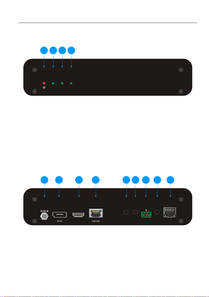
3.1 WolfPack™ 4K/60 HDR HDMI Over IP-TX Front Panel
① POWER LED: The LED illuminates red when power is applied.
② LINK LED: The LED indicates if Ethernet packets are transmitted.
LED off: Packets are not transmitted
LED blinking: Packets are transmitted
③ HDMI LED: The LED illuminates green when the HDMI video source is selected.
④ DP LED: The LED illuminates green when the DP video source is selected.
3.2 WolfPack™ 4K/60 HDR HDMI Over IP-TX Rear Panel
① DC 12V: DC barrel port for AC power adapter connection.
② DP IN: DisplayPort input port to connect DP video source device.
③ HDMI IN: Type-A female HDMI port to connect HDMI video source device.
④ 10G LAN: RJ45 port to connect RX or Network Switch with CATx cable.
5
Page 11
4K IP Streaming Extender
LINK
HDMI
1
2
3
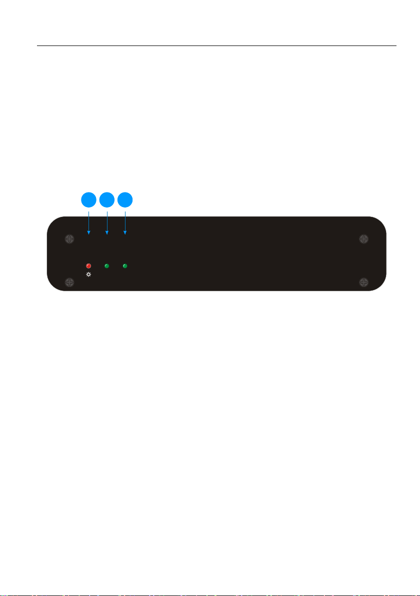
⑤ IR IN: 3.5mm jack to connect an IR receiver for IR routing control.
⑥ IR OUT: 3.5mm jack to connect an IR emitter for IR routing control.
⑦ RS232: 3-pin terminal block for RS232 routing control. Supports point to point
unicast and point to multipoint broadcast configuration.
⑧ AUDIO IN: 3.5mm jack to connect audio source.
⑨ ETHERNET: RJ45 port to connect PC that need to access LAN.
3.3WolfPack™ 4K/60 HDR HDMI Over IP-RX Front Panel
① POWER LED: The LED illuminates red when power is applied.
② LINK LED: The LED indicates if Ethernet packets are received. It also indicates if
FPGA SERDES can detect a valid signal.
LED off: Packets are not received and RX SERDES is NOT linked.
LED blinking: Packets are received and the RX SERDES IS linked.
Steady light: Packets are not transmitted and the RX SERDES is linked.
③ HDMI LED: The LED illuminates green when connect to display.
6
Page 12
4K IP Streaming Extender
HDMI OUT AUDIO OUT
IR IN
RS232
Tx Rx
IR OUT DC 12V
ETHERNET
1
2
3
4
5
6
7
8
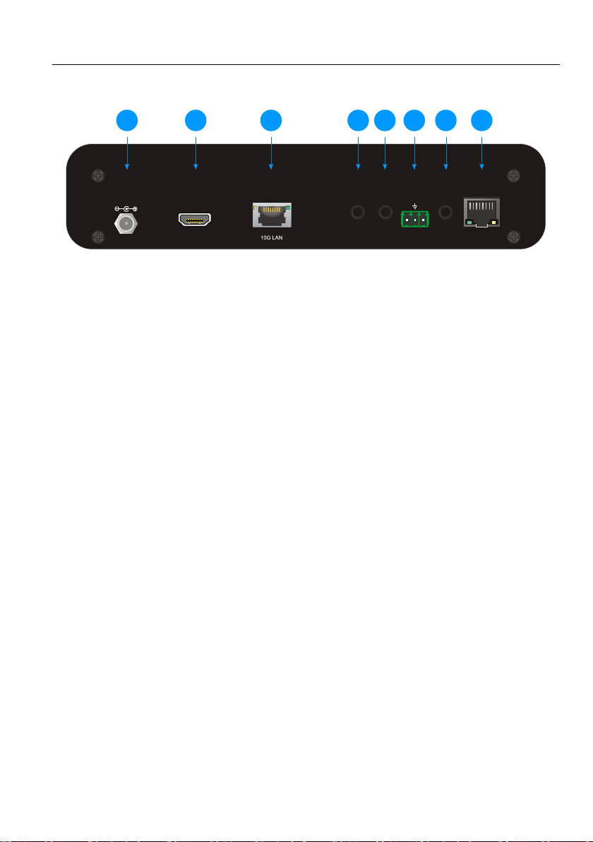
3.4WolfPack™ 4K/60 HDR HDMI Over IP-RX Rear Panel
① DC 12V: DC barrel port for AC power adapter connection.
② HDMI OUT: Type-A female HDMI port to connect HDMI display device.
③ 10G LAN: RJ45 port to connect TX or Network Switch with CATx cable.
④ IR IN: 3.5mm jack to connect an IR receiver for IR routing control.
⑤ IR OUT: 3.5mm jack to connect an IR emitter for IR routing control.
⑥ RS232: 3-pin terminal block for RS232 routing control. Supports point to point
unicast and point to multipoint broadcast configuration.
⑦ AUDIO OUT: 3.5mm jack to connect audio output device.
⑧ ETHERNET: RJ45 port to connect PC that need to access LAN.
7
Page 13

4K IP Streaming Extender
4. System Connection
4.1 Usage Precaution
Make sure all components and accessories included before installation.
System should be installed in a clean environment with proper temperature and
humidity.
All of the power switches, plugs, sockets, and power cords should be insulated and
safe.
4.2 Connection Type
There are five types of connection way can be chosen:
Extender (Point-to-Point Application)
In a point to point configuration, there is no need for a Switch. Distribute full,
uncompressed data up to 4K@60Hz 4:4:4 resolution as well as 1G Ethernet, audio and
control signals over IP - Surpass the limitations of other technologies.
Splitter (Point-to-Many Application)
With only one IPA100E-TX transmitter and one 10G Ethernet Switch, any A/V signal
can be flawlessly and instantly distributed to a near limitless number of receivers and
screens, any number of times.
Matrix (Many-to-Many Application)
The combination of switching and splitting enables a completely scalable matrix
system. Independently route video, audio, IR and RS232 control signal from any source
to any endpoint. The IPA100 series allows for on-the-fly upgrading and a virtually
unlimited number of I/O ports.
8
Page 14
4K IP Streaming Extender
Video Wall Application
Create and manage video walls in setups up to 5x5 screens. The IPA100 series
product line features full bezel correction and instant seamless switching of full
bandwidth source material as well as further innovative features for video wall
management.
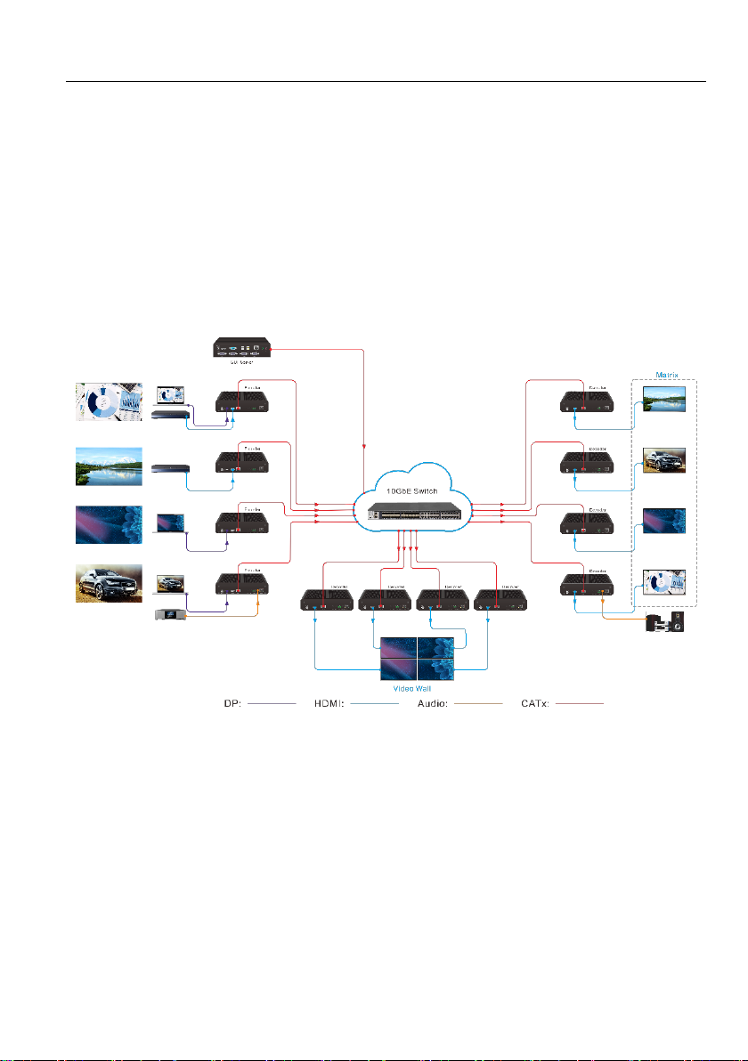
4.3 System Diagram
The following diagram illustrates typical input and output connection that can be utilized
with the extender:
Matrix System
9
Page 15

4K IP Streaming Extender
4.4 Hardware Setup
The IPA100 extender set you have received include one transmitters (TX) and one
receivers (RX).
Please follow the steps below to complete the system installation:
1) Connect the power supply (12V DC) to the power connectors.
2) Connect the video/graphics source device to the HDMI input connector on each TX
unit.
3) Connect the video display device to the HDMI output connector on each RX unit.
4) (Optional) Connect audio sources to the audio input connector of the TX if you
want to test additional audio extension.
5) (Optional) Connect audio output device (e.g. speaker or headphone) to the audio
output connector of the RX if you want to test additional audio extension.
6) (Optional) Connect RS232 devices as needed if you want to test RS232 serial
extension between TX and RX units.
7) (Optional) Connect GbE compatible Ethernet devices as needed for testing the 1
Gig Ethernet ports of any TX or RX units.
8) (Optional) Connect compatible IR emitter modules to the IR output connectors of
any TX or RX.
9) (Optional) Connect compatible IR receiver modules to the IR input connectors of
any TX or RX.
10) Connect a 10G Ethernet cable (Cat-6a recommended) from the 10GbE port each
TX and RX unit to any available 10GBaseT port.
11) Connect the control PC to the GbE port of any HDTVIPA100 device or to a
Cat-x port of the 10GbE switch (except the management/console port of the
switch).
12) The hardware setup is now complete.
Note that any TX can also be connected directly to a RX without the 10GbE switch
in the middle using fiber cable or Cat-x cable to test point to point functionality.
10
Page 16

4K IP Streaming Extender
Manufacturer
Model Number
BlackBox
LGB5028A
Netgear
ProSAFE PLUS XS708E
Netgear
ProSAFE Smart XS708T/712T/716T/728T/748T
Netgear
M4300 Series
Netgear
M7300-24XF XSM7224S
Speed-NT
UK-6000 Series
Extreme Network
Summit X670 Series
Arista Networks
7050X Series
Note that in order to test switching functionality through a 10GbE switch; you must
use a 10GbE layer 2, layer 3 switch with IGMP snooping capabilities. Ensure that
the IGMP snooping setting is enabled and broadcast setting is disabled using the
appropriate configuration software provided the switch manufacturer.
Switch list: The below table contains the Ethernet switches validated and known to
work with IPA series device.
Note that NetGear M4300 Series are recommended.
11
Page 17
4K IP Streaming Extender
5. GUI Control
5.1 Basic Configuration
The web-based GUI is used to configure and control signal extension, routing and
switching between TX and RX units.
Before proceeding GUI, make sure all IPA units are powered ON. Then ensure that the
IP addresses of PC and all IPA units are on the same local area network (LAN). If this is
not the case, please manually set IP address mode as DHCP.
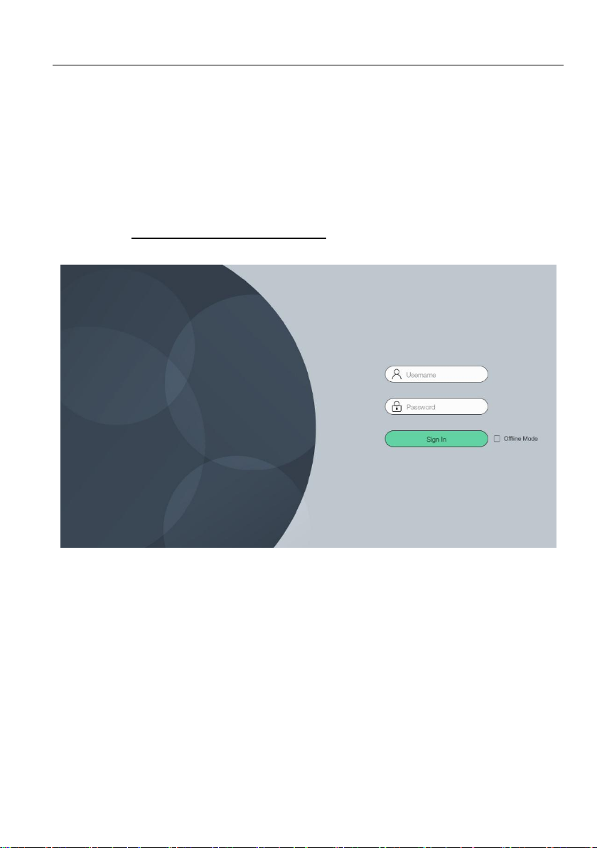
Please type the IP Address of the control PC in the internet browser, and it will enter
the below log-in webpage:
Username: admin
Password: admin
Please type the user name and password, and then click Sign In.
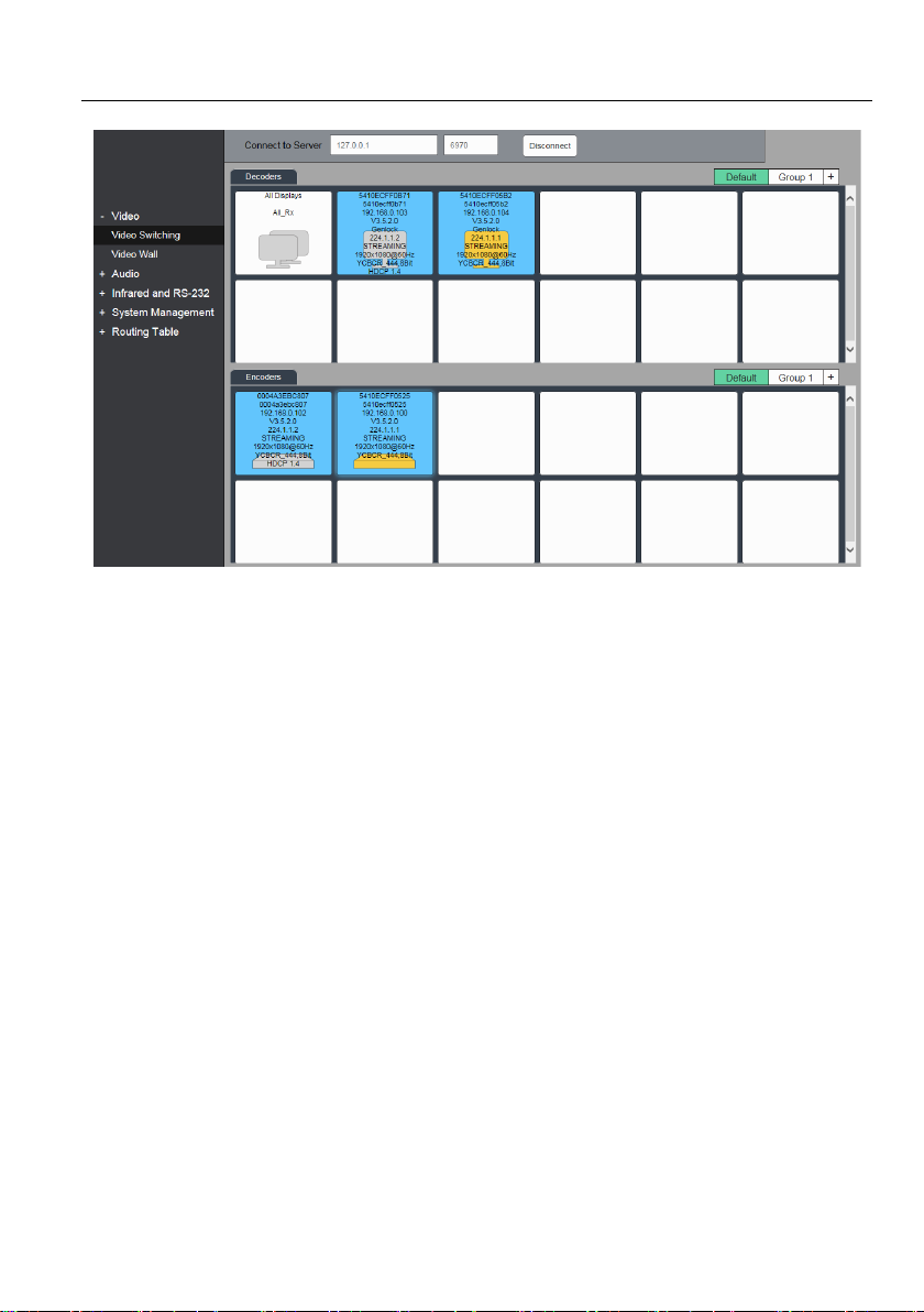
Upon launch, the main interface appear as per the picture below:
12
Page 18
4K IP Streaming Extender
5.2 Device Configuration
Before starting the GUI control, make sure the control PC is connected either directly to
the network switch or to the Gigabit Ethernet port on one of the devices (TX or RX).
Upon launch, the main window will open up in the “Video Switching” tab. It will discover
all the TX and RX devices on the network and display them inside the application GUI.
The first step is to connect to the Server. Enter the IP address and click connect.
The default Server setting is:
IP Address: 127.0.0.1
Port Number: 6970
All connected devices on the network will appear as a blue tiles within the GUI window.
Each tile will identify the “Hostname” of the device. The default device “Hostname” is
the MAC address. Note that the “Hostname” can be updated at any time. The “IP
Address” of the device is also indicated within the tile.
If a source device is connected to the HDMI port of the TX, a picture illustrating a
source device will appear within the tile belonging to the TX along with information
about the video feed. Similarly, if a display device is connected to the RX, an illustration
of a display will appear within the corresponding RX tile. If no device is visible within the
tile, it means that the device is connected and detected but no source (or display)
13
Page 19
4K IP Streaming Extender
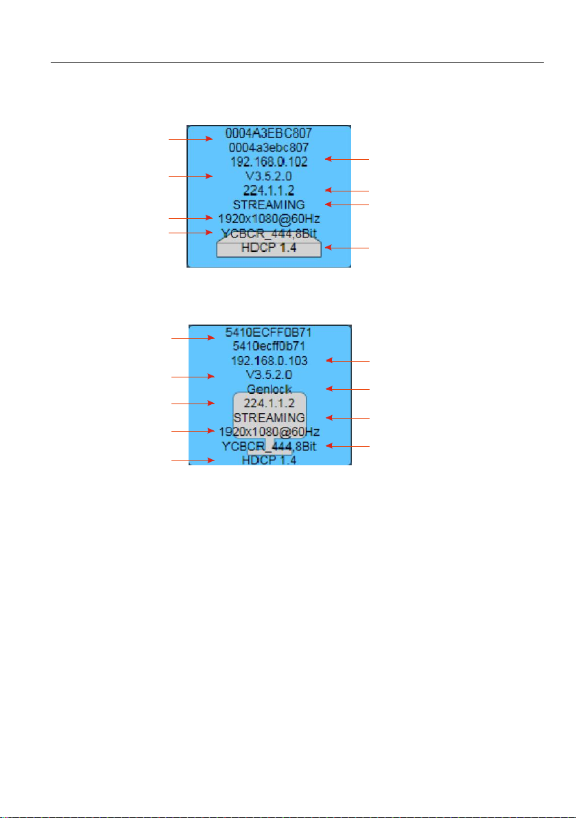
Hostname
IP Address
Color Space
Streaming/Stopped Status
Software Version
Multicast Streaming Address
Video Resolution
HDCP Version
(MAC Adress)
Hostname
IP Address
HDCP Version
Video Resolution
Multicast Streaming
Address
Software Version
Current Video Mode
Streaming/Stopped Status
Color Space
(MAC Adress)
device is connected to the TX (RX).
TX Device tile info
The device tile information can be set by following the below steps:
1) Right click TX or RX device tile.
2) Click the option “Setting”
3) Select the Tile Info
4) Select the type of information which needs to be displayed.
RX Device tile info
14
Page 20
4K IP Streaming Extender
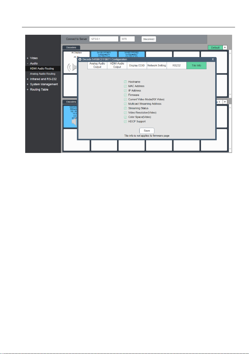
5.3 Video Routing Tab
Video Routing tab is used to manage video routing between TX and RX devices. There
are three modes available for Video Routing:
Genlock
The primary benefit of the Genlock mode is very low (zero-frame) latency between the
source and displays. The display is genlocked to the source as if it is directly
connected.
When Genlock is selected, what is sent out to the display is a byte-by-byte replication
of what was received from the source.
The only exception is in the occasional instance when the input video has too high a
bandwidth to fit into a 10G network link. In these cases, the video is slightly
compressed to bring the stream down below the 10G limitation of the network. An
example of a signal that is over 10G is a UHD 60Hz with full color sampling (RGB or
YCbCr 444).
Genlock Scaling
This mode combines the low latency and source locking benefits of the Genlock mode
with the output scaler found in the Fast Switch Full Screen mode.
15
Page 21
4K IP Streaming Extender
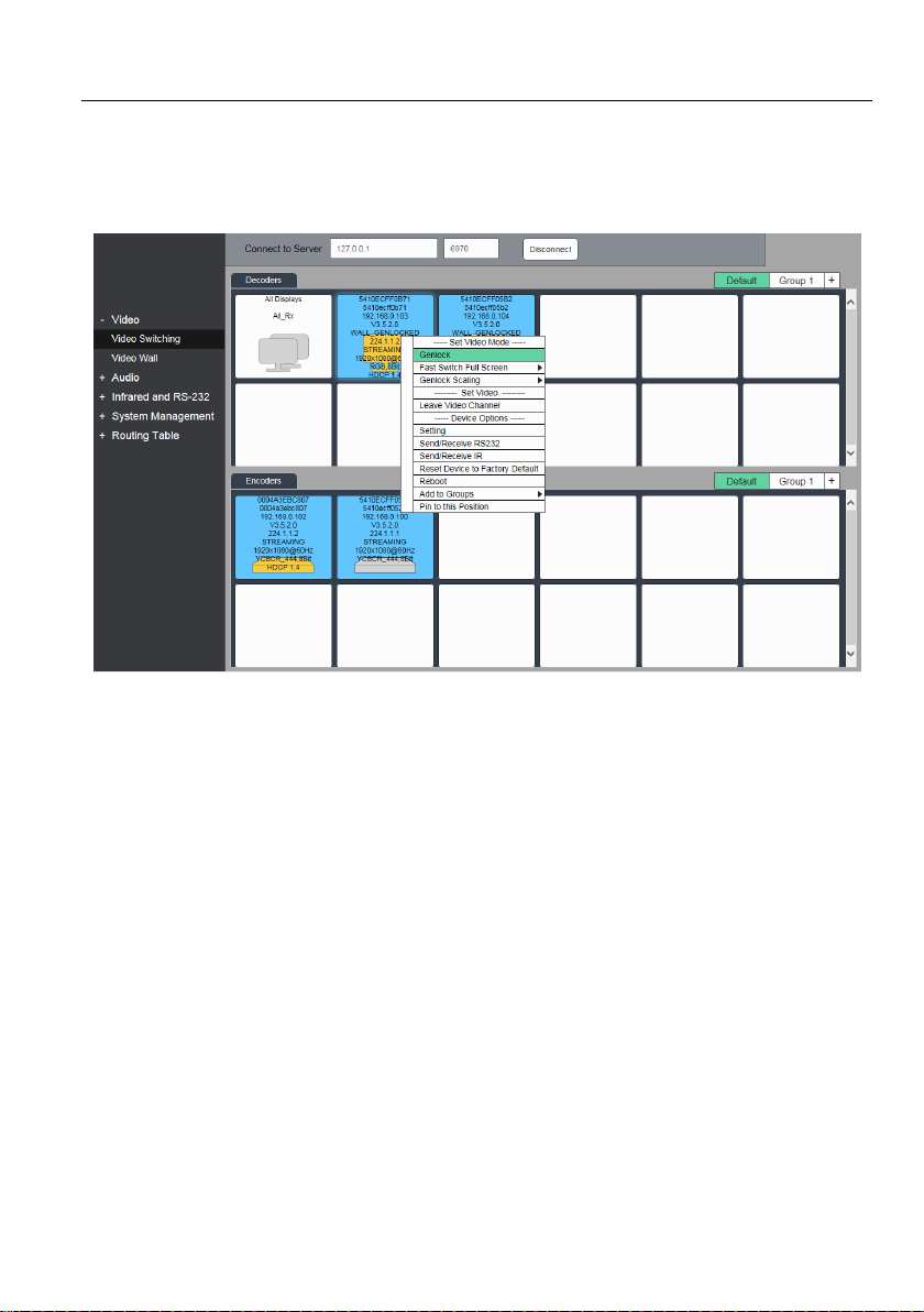
Fast Switch Full Screen
The primary benefit of the Fast Switch Full Screen mode is that source switching
occurs quickly, it in fact appears seamless to the human eye.
All the RX devices are listed on the top half of the Decoder section. Similarly, all the TX
devices are listed on the bottom half under the Encoder section.
5.3.1 Video Switching
Here select Genlock mode as an example to join TX and RX devices:
1) Verify if the RX tile is displaying that device is currently in Genlock mode. The
information indicated in a device tile includes the Video mode. If Genlock is not the
currently active mode, apply the setting as follows:
a) Right mouse click over the appropriate Decoder (RX) tile.
b) In menu that appears select Genlock as the Video Mode.
2) Next join the RX to TX.
a) In the Encoder section, select a TX by clicking on its associated active tile with
left mouse button.
b) While holding down the left button, drag the TX tile over the RX tile it is to be
joined with (RX discovered on the network are displayed under the Decoders
section) and then release the mouse button to drop the TX tile onto the RX tile.
16
Page 22

4K IP Streaming Extender
c) TX and RX are now joined.
Video source connected to the Encoder (TX) now appears on the display connected to
the Decoder (RX).
If the video is not being displayed, then there are a few things that should be verified:
Ensure that the network switch has been properly configured.
Confirm that the display can support the source resolution being sent.
Also, verify that the HDMI cable being used is of good quality. This is particularly
important for 4K 60Hz which requires a premium HDMI cable.
To assign a different source to a Decoder (RX), repeat the above steps switching a
different TX to an RX to associate the receiver itself to the new source.
Note: Regarding Fast Switch Full Screen and Sync Scaling, please refer to Genlock
mode.
5.3.2 Send single source to all RX devices
To send the same source to ALL RX devices, simply select the TX unit in then
Encoders section, and then click the ALL Displays in the Decoder section.
Comment: To verify which RX and TX are joined together, with the left mouse click on
the Decoder (RX) or Encoder (TX) tile it is desired to see the connection status for. All
the joined tiles will be highlighted by yellow.
5.3.3 Stopping/Starting Video
To stop video being transmitted from an Encoder (TX), right click on appropriate TX,
select Stop Video.
To start or restart video transmission, right-click on the appropriate Encoder (TX) and
select Start Video.
5.3.4 Disconnecting Source from RX
To disconnect a Decoder (RX) from a TX source, right click on the RX tile and select
Leave Video Channel.
17
Page 23
4K IP Streaming Extender
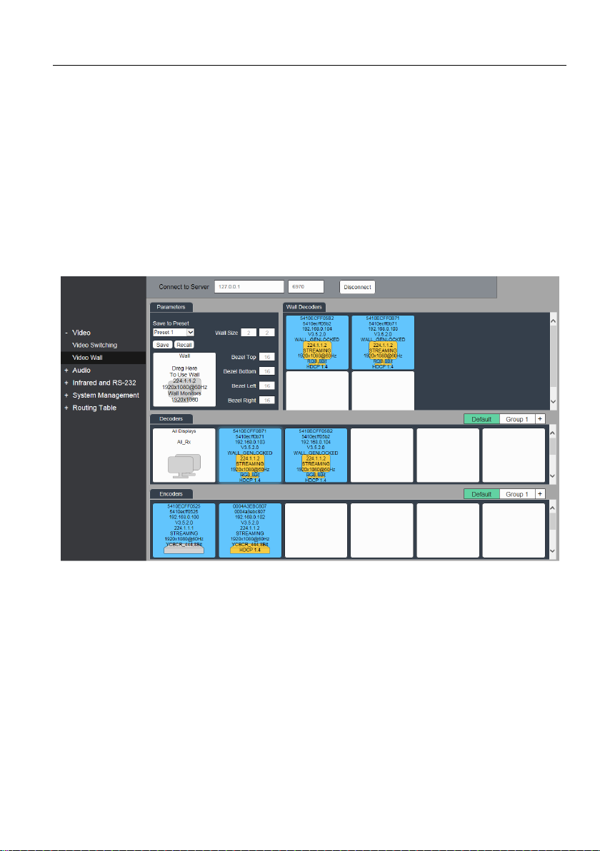
5.4 Wall Routing Tab
Wall Routing tab allows for a single source (TX) to be assigned to multiple Decoder
(RX) units and loaded across multiple displays appearing as a single wall. Figure below
illustrates the Wall Routing tab. The top portion is reserved for configuring and setup of
the Wall, while the bottom half lists all available TX (Encoder) and RX (Decoder) units.
The wall size can be adjusted by changing the number of rows and columns. Bezel
correction values are in number of image pixels. The default value is set to 16 pixels.
Increase this value to adjust for thicker bezels while a value of zero would indicate no
bezel correction is to be applied.
Note: Source must be progressive.
5.4.1 Configuring a Video Wall
1) Set the Wall Size.
a) Under the Wall Parameter section enter the number of Rows and Columns that
are to make up the Video Wall (maximum 5x5).
2) Drag and drop Decoder devices onto individual wall decoder tiles.
a) From Wall section, left click on it to select one tile.
b) Drag and drop decoder device onto the blank tile on the Wall Decoders.
3) Next drag an encoder source tile and drop it onto the tile that is labeled Wall: Drag
Here To Use Wall.
18
Page 24
4K IP Streaming Extender
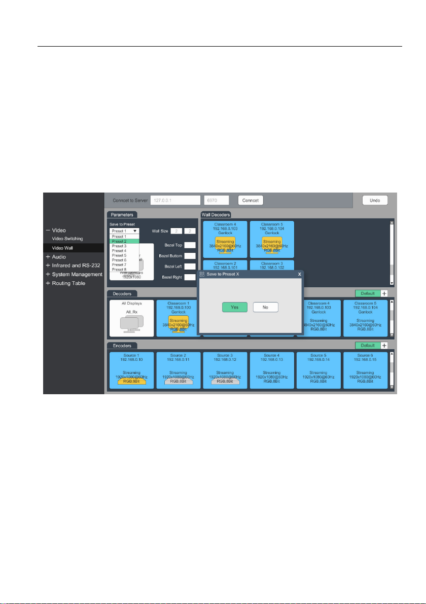
4) The source will now be visible across the whole Wall matrix.
5) If appropriate adjust the Bezels correction values, to adjust the Bezel thickness that
is to be applied.
Comment: To apply the new bezel values, it may be necessary to redo the drag and
drop of the Encoder (TX) onto the TX Wall tile.
5.4.2 Preset Setting
After video wall setting, select the Preset 1~8, and then click Yes to save the current
video wall setting.
19
Page 25
4K IP Streaming Extender
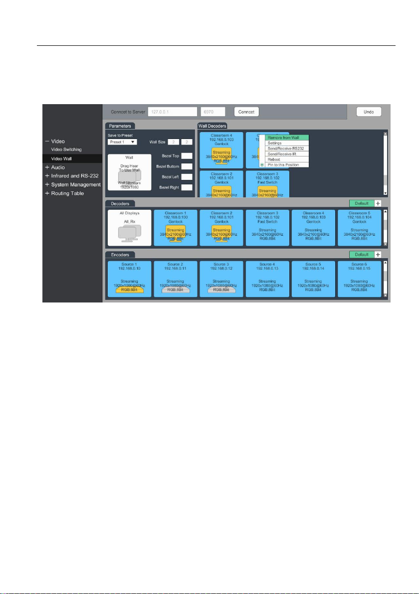
5.4.3 Removing Decoder (RX) from Video Wall
To remove a decoder from the Wall, right click on appropriate RX tile and then select
option Remove from Wall.
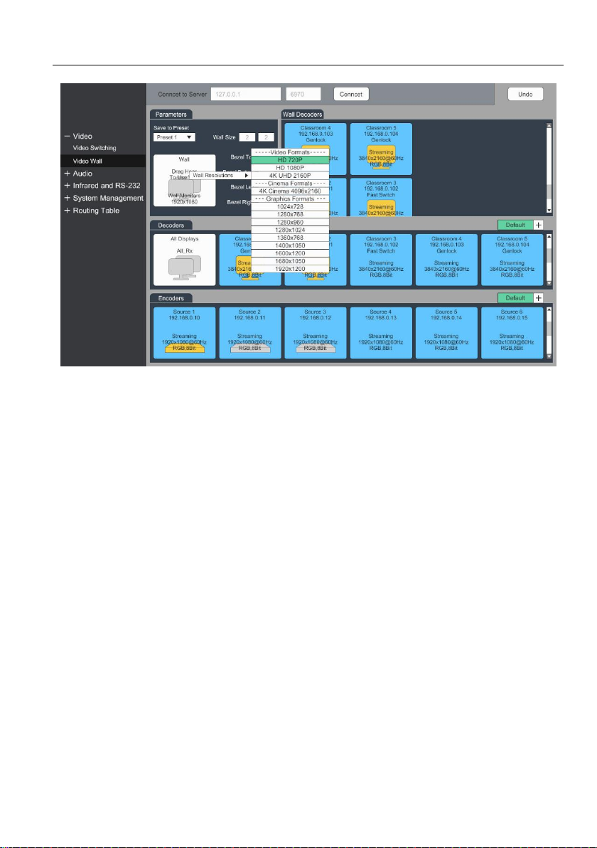
5.4.4 Changing Output Resolution for Video Wall Decoders
To control the decoder output resolution, right click the Wall tile on the Parameters
section.
Select Video Wall Resolutions and then choose the appropriate resolution from list of
available resolutions.
Selected output resolution is applied to all decoders that are part of the wall matrix.
20
Page 26
4K IP Streaming Extender
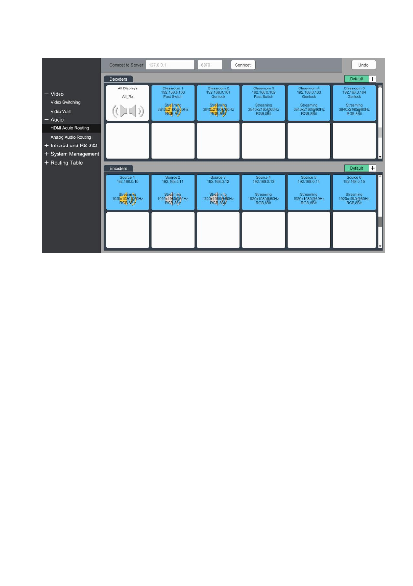
5.5 HDMI Audio Routing Tab
HDMI audio is routed separately from the video. In many cases, it is required to route
HDMI audio separately. As an example, routing the audio to additional or different
decoders.
Exception: When in Genlock mode, the HDMI audio follows the Video when one or
more Decoders (RX) are joined with an Encoder (TX) from any of the video routing tabs
(Video, Wall,, etc.). Simply put this means that when an RX device is in Genlock, it
receives both the HDMI video and the HDMI audio.
To route HDMI audio, select the tab labeled HDMI Audio Routing.
All the RX devices are listed on the top half of the Decoder section. Similarly, all the TX
devices are listed on the bottom half under the Encoder section.
21
Page 27
4K IP Streaming Extender
First verify if appropriate TX and RX units that will have the HDMI audio routed are
joined:
1) Verify if the Decoder (RX) is currently joined to the appropriate Encoder (TX).
a) Click on the RX and the Encoder (TX) it is joined to will be highlighted by yellow.
b) Selecting the TX will highlight all the other RX’s joined to the same TX.
2) If the appropriate Encoder (TX) is not joined presently to the Decoder (RX) proceed
to join them:
a) In the Encoder section, select a TX by clicking on its associated active tile with
the left mouse button.
b) Drag and drop the TX tile over the RX tile it is to be joined with.
c) TX and RX are now joined.
d) Repeat above steps if additional RX are to be joined to the same TX.
To control if the HDMI audio is sent out on the HDMI output port or the Analog output
port complete the following steps:
1) Right click a Decoder (RX) and from the menu select Settings.
2) To direct audio to the HDMI output, select the HDMI Encoder tab and then choose
either:
a) HDMI Audio (All Available Channels) to select the original multichannel audio;
b) HDMI Audio (Stereo Downmix) to select downmixed 2-channel audio.
22
Page 28
4K IP Streaming Extender
3) To send the audio to the Analog output connector, select the Analog Audio Output
tab and choose HDMI Audio (Downmix) from the pull-down menu.
4) Click Save to apply changes.
5) The sound device connected to the RX will now play out the HDMI audio stream.
Tip: If audio is not playing out, confirm that the TX device is streaming. Also, verify the
RX audio output settings are correct.
Note: Downmixed 2-channel audio is not available for proprietary Dolby or DTS audio
formats
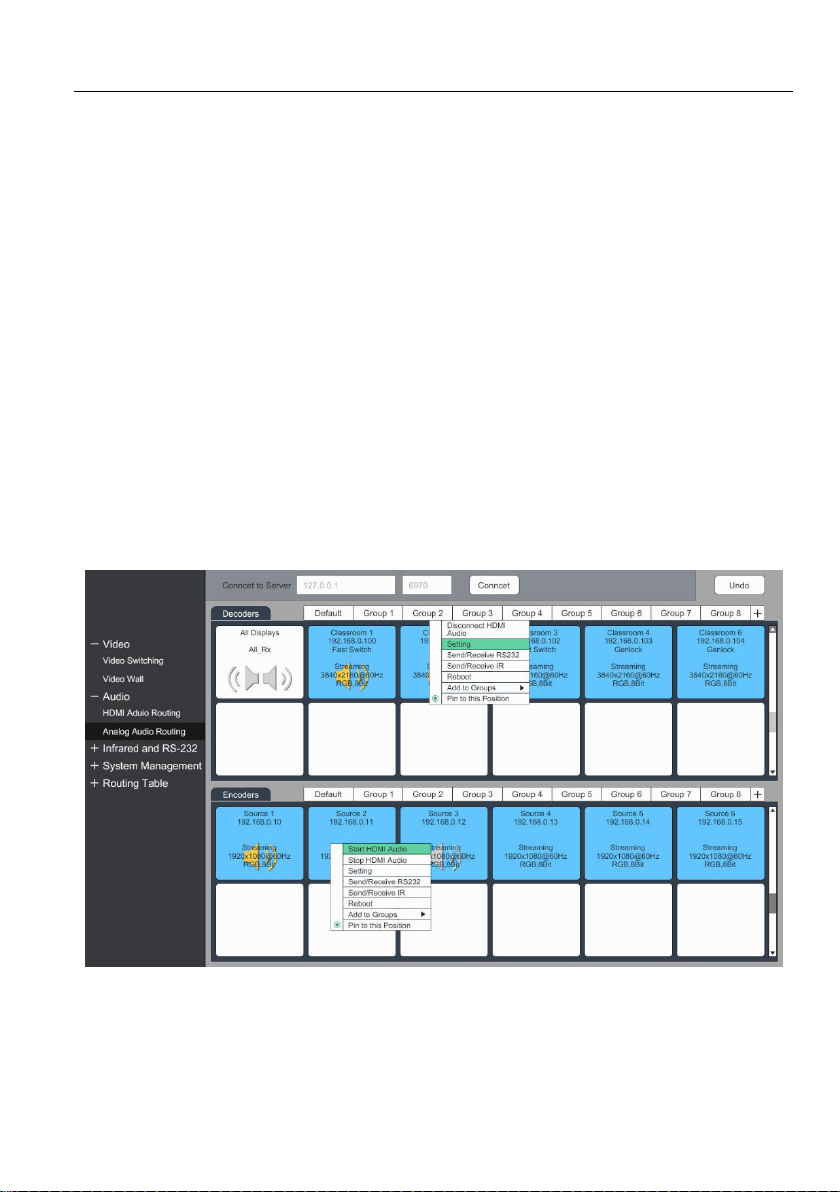
5.6 Analog Audio Routing tab
The Analog Audio tab is used to setup and manage Analog Audio Routing between TX
and RX devices.
All the RX devices are listed on the top half of the Decoder section. Similarly, all the TX
devices are listed on the bottom half under the Encoder section.
First verify if appropriate TX and RX devices that will have the Analog Audio routed are
joined:
1) Verify if the Decoder (RX) is currently joined to the appropriate Encoder (TX).
a) Click on the RX and the Encoder (TX) it is joined to will be highlighted by yellow.
23
Page 29

4K IP Streaming Extender
b) Selecting the TX will highlight all the other RX’s joined to the same TX.
2) If the appropriate Encoder (TX) is not joined presently to the Decoder (RX) join the
RX to TX:
a) In the Encoder section, select a TX by clicking on its associated active tile with
the left mouse button.
b) Drag and drop the TX tile over the RX tile it is to be joined with.
c) TX and RX are now joined.
d) Repeat above steps if additional RX are to be joined to the same TX.
To control where and how Analog Audio is sent out complete the following steps:
1) Connect a speaker or any type of analog audio receiver to the RX device.
2) Right click an RX device and select Settings.
3) Choose how the audio is to be sent out on the Analog output connector:
a) Click on the Analog Audio Output tab
b) Choose the desired audio output option from the drop-down list provided:
HDMI Audio (Downmix)
Analog Audio
4) Click Save to apply changes.
5) The sound device connected to the RX will now play out the Analog audio stream.
Tip: If audio is not playing out, confirm that the TX device is streaming. Also, verify the
RX audio output settings are correct.
24
Page 30

4K IP Streaming Extender
5.7 RS-232 Routing Tab
The RS-232 Routing tab is used to setup and manage RS-232 data routing for devices.
There are two sections provided in the interface, first is labeled Senders (TX), while the
second is labeled Receivers (RX). Each device discovered on the network, whether a
Transmitter or a Receiver, is listed in both groups because each device can both send
and receive RS-232 data.
Select the RS-232 Routing tab. Then to pair a device, drag the tile representing the TX
and drop it over a device the desired RX to create one-way communication.
To create a two-way RS-232 path between two devices, two separate pairings are
required.
Repeat step 1 but in reverse to create the second pairing.
5.7.1 Assign Sender to all Receivers
To distribute RS-232 data from a single Sender unit to all Receiving devices, click the
respective Sender’s tile, and then click All Receivers tile in the RS-232 Routing tab.
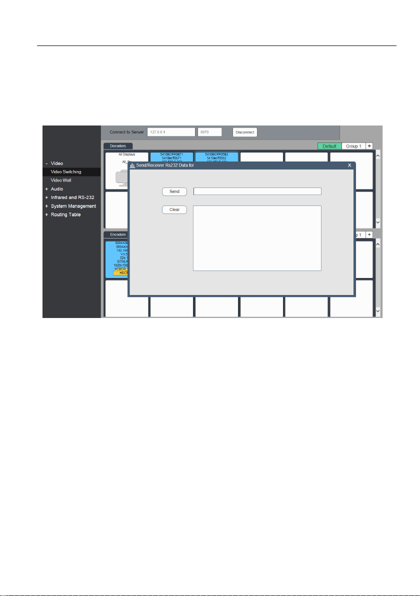
5.7.2 To send RS-232 data from Control layer to a device
1) Right click the Sender or Receiver tile.
2) Select Send/Receive RS232 dialog box.
25
Page 31
4K IP Streaming Extender
3) A Send/Receive RS-232 dialog box opens.
4) Next to the Send button enter the RS-232 string that is to be sent.
5) Then click the Send button to send out the string.
6) Paired devices will receive the RS-232 data.
Note: API Server is used to device debug.
RS-232 Limitations
Supported baud rate ranges from 9600 bauds to 115200 bauds.
A Sender can either send RS-232 data to a specific device (unicast) or broadcast to all
devices active on the network (broadcast). Should be noted however, that a sender
cannot send data simultaneously to a range of devices using multi-unicast.
26
Page 32
4K IP Streaming Extender
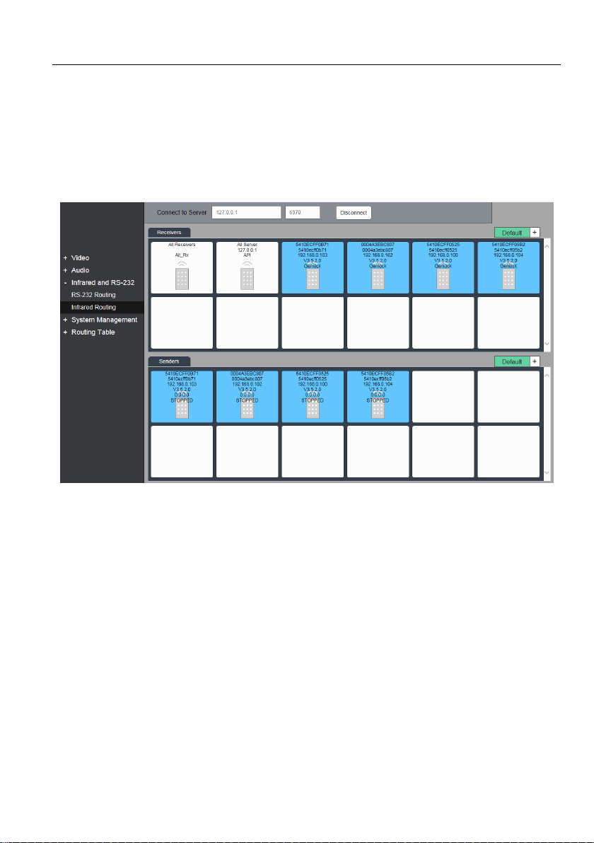
5.8 Infrared Routing Tab
The Infrared Routing tab is used to setup and manage IR data routing for devices.
There are two sections provided in the interface, first is labeled Senders (TX), while the
second is labeled Receivers (RX). Each device discovered on the network, whether a
Transmitter or a Receiver, is listed in both groups because each device can both send
and receive IR data.
Select the Infrared Routing tab. Then to pair a device, drag the tile representing the TX
and drop it over a device the desired RX to create one-way communication.
To create a two-way IR path between two devices, two separate pairings are required.
Repeat step 1 but in reverse to create the second pairing.
5.8.1 Assign Sender to all Receivers
To distribute IR data from a single Sender unit to all Receiving devices, click the
respective Sender’s tile, and then click All Receivers tile in the IR Routing tab.
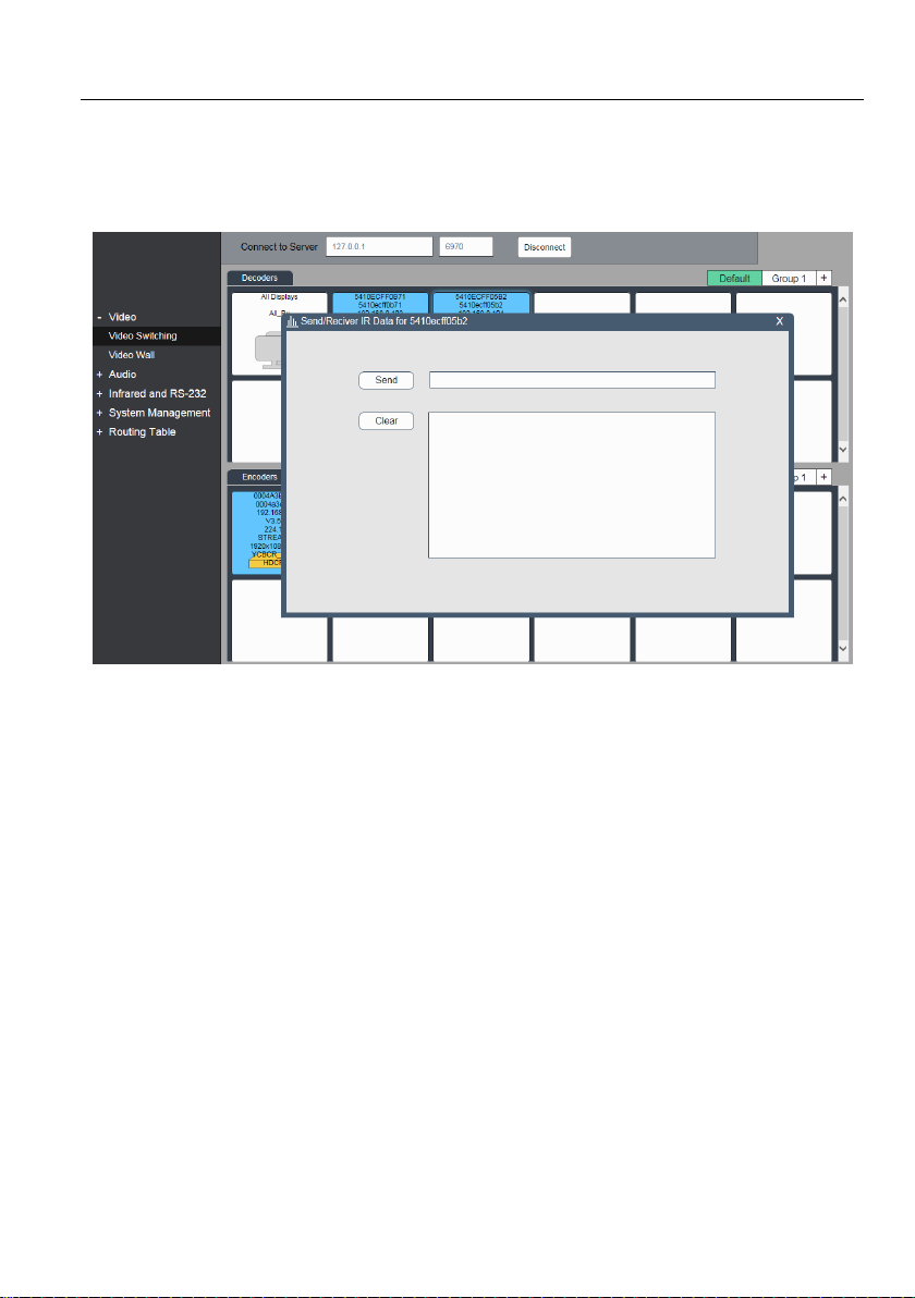
5.8.2 To send IR data from Control layer to a device
1) Right click the Sender or Receiver tile.
2) Select Send/Receive IR dialog box.
3) A Send/Receive IR dialog box opens.
27
Page 33
4K IP Streaming Extender
4) Next to the Send button enter the IR string that is to be sent.
5) Then click the Send button to send out the string.
6) Paired devices will receive the IR data.
Note: API Server is used to device debug.
Infrared Limitations
A Sender can either send IR data to a specific device (unicast) or broadcast to all
devices active on the network (broadcast). Should be noted however, that a sender
cannot send data simultaneously to a range of devices using multi-unicast
The data format used when sending IR data from control layer to a device is ‘Pronto’.
The link below points to a good description of Pronto format definition with examples.
http://www.remotecentral.com/features/irdisp1.htm
The pronto format is a series of hex numbers that describe everything that is needed to
generate the required waveform. It includes the carrier frequency, the ON/OFF period
along with data and error checksum.
Large libraries of Pronto IR codes are publicly available and easy to find on the Web.
The code below is a Pronto string to turn Sony BlueRay player ON and OFF
0000 0067 0000 0015 0060 0018 0030 0018 0018 0018 0030 0018 0018 0018 0030
0018 0018 0018 0018 0018 0018 0018 0030 0018 0018 0018 0030 0018 0030 0018
0018 0018 0030 0018 0018 0018 0018 0018 0018 0018 0030 0018 0030 0018 0030
01FE
28
Page 34
4K IP Streaming Extender
5.9 Global Command Options and Settings
To access a Device’s options, right click any device tile.
Note: Device options are available from all detected devices from any of the interface
tabs, Video Switching, HDMI Audio, etc.
5.9.1 Decoder Settings options
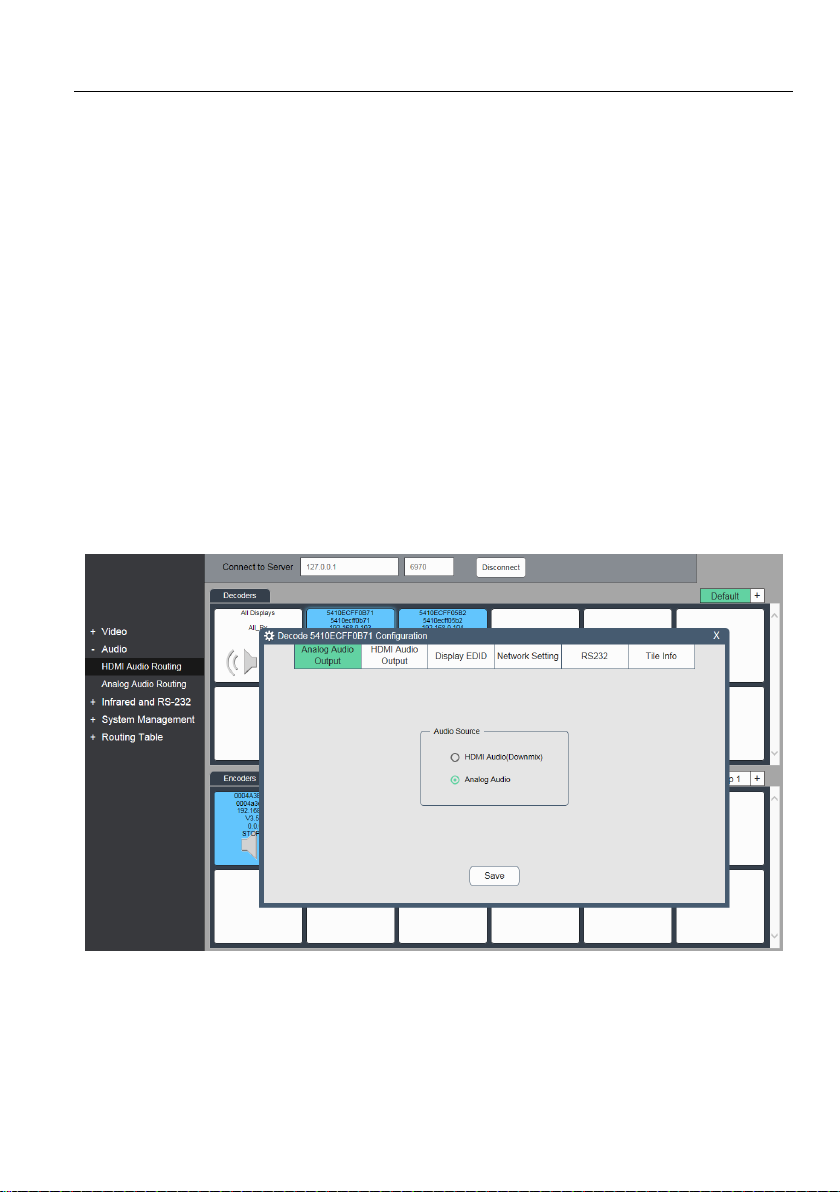
The following section illustrates the Decoder (RX) device settings dialog box.
Analog Audio Output Settings
Use this tab to select the Audio source for the Analog Audio Output port.
There are four source options:
Analog audio: Analog stream coming from an encoder
HDMI Audio: 2-channel downmixed version of the original HDMI audio from an
encoder.
29
Page 35
4K IP Streaming Extender
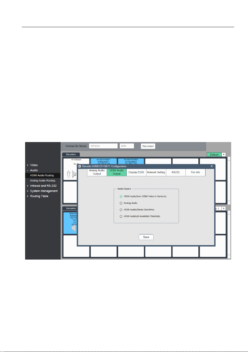
HDMI Audio Output Settings
Use this tab to control which audio source is going out on the HDMI port. There are
three options.
HDMI Audio (HDMI Video in Genlock Mode): The original HDMI audio stream received
with the video from an Encoder is used if the Decoder is in genlock mode. If the
Decoder is in any other video mode, then the HDMI audio is sent separately.
Analog Audio: The received analog audio stream from an Encoder is embedded into
the HDMI output.
HDMI Audio (Stereo Downmix): It is not available for IPA Series now.
HDMI Audio (All Available Channels): The multichannel audio (up to 8 channels)
received as a separate HDMI audio stream from an Encoder, is embedded into the
HDMI output signal.
30
Page 36
4K IP Streaming Extender
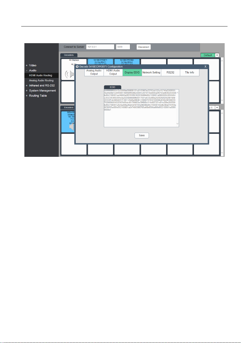
Device EDID
Use this tab to access and save the EDID coming from the display that is connected to
the RX unit. Use the save button to save the EDID to file. It is also possible to select
and copy the EDID Hex values directly and paste into an editor such as Notepad.
When no display is connected, the EDID view is blank.
31
Page 37
4K IP Streaming Extender
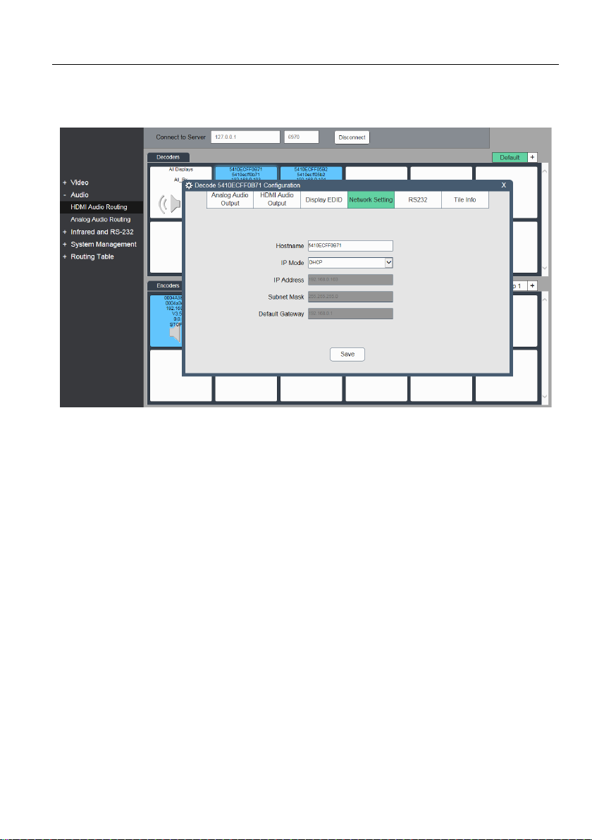
Network Setting
Use this tab to modify the device 'hostname' and configure device IP address.
By default the device ‘hostname’ equals the device MAC address.
The device MAC address is also used as device ID by Control API Server. To rename a
device, enter a name (e.g. “room1”) into the ‘Hostname’ edit box. Press ‘Save’ button to
save new host name. The host name is persistent and kept until the device is forced
back to a factory default.
IP Address can be set to be either ‘DHCP’ or ‘Manual’
Select “DHCP” to receive IP address from DHCP server or be assigned Auto-IP
address in the 169.254.X.X range in the case there is no DHCP server on the
network.
Select “Manual” to set static IP address (IPV4 address, subnet mask and gateway
address)
Press ‘Save’ to save new IP address. New IP mode settings are stored in non-volatile
memory and kept until the device is forced back to factory default.
Note: Special attention is required when assigning a manual IP address. The address
has to be both unique and reachable. Any mistake when enter the IP address, subnet
mask or gateway address can render the device unreachable.
32
Page 38
4K IP Streaming Extender
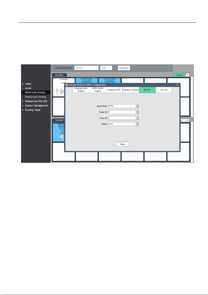
RS232
Use the RS232 tab to modify/edit the RS232 settings.
Select the desired port configuration (Baud Rate, Data Bit, Stop Bit and Parity). Click
the “Save” button to save the updated RS-232 configuration. New RS-232 settings are
kept until device is factory reset (forced to factory default settings).
33
Page 39
4K IP Streaming Extender
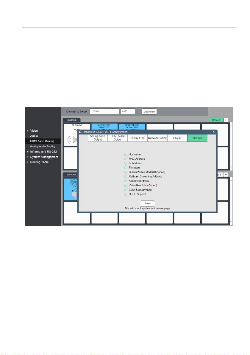
Tile Info
Use the Tile Info tab to select the type of information which needs to be displayed by
following the below steps:
1) Right click Decoder device tile.
2) Click the option “Setting”.
3) Select the Tile Info.
4) Select the type of information which needs to be displayed.
34
Page 40
4K IP Streaming Extender
5.9.2 Encoder Settings options
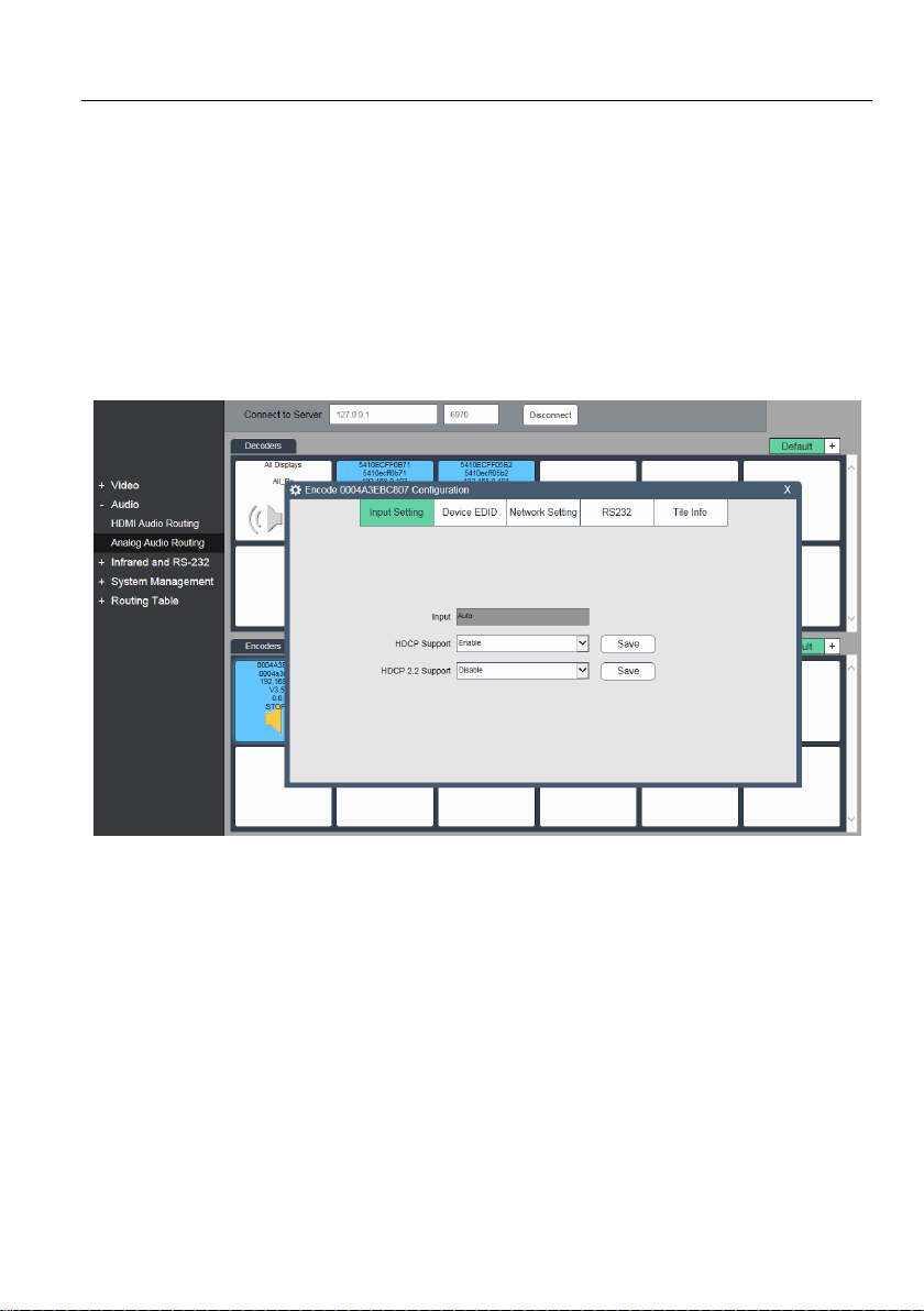
The following section illustrates the Encoder (TX) device settings dialog box.
Input Setting
Use this to Enable or Disable HDCP support.
If HDCP support is disabled, streaming video from a HDCP source to screen will result
in black image displayed on screen
It is also possible to only enable HDCP 1.4 by checking the ‘Disable HDCP 2.2 Support
Note: Manually select input is not available, if both HDMI and Display Port are
connected, the HDMI input will take precedence.
35
Page 41
4K IP Streaming Extender
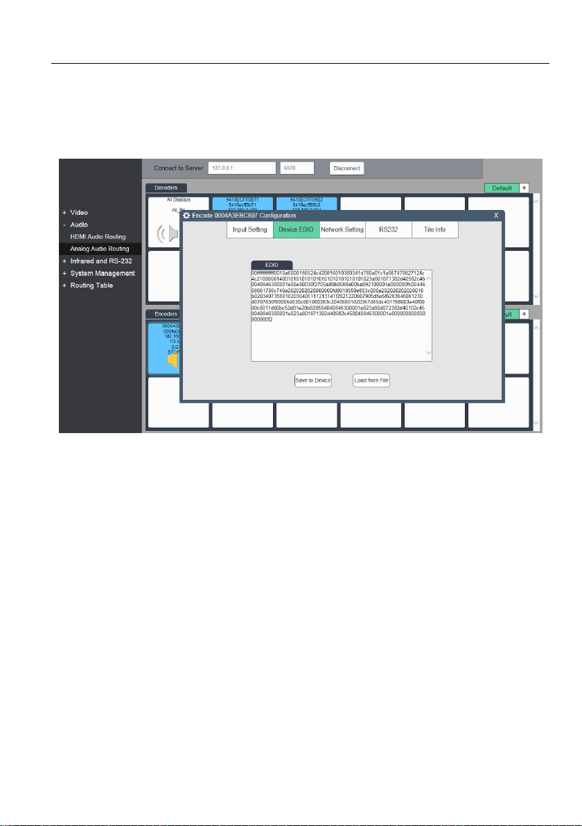
Device EDID
This tab is used to access and manipulate the Encoder (TX) EDID display data; it
exposes the source devices the ability to change, save EDID data to Device or Load
EDID data from File.
36
Page 42

4K IP Streaming Extender
Network Setting
Use this tab to modify the device 'hostname' and configure device IP address.
By default the device ‘hostname’ equals the device MAC address.
The device MAC address is also used as device ID by Control API Server. To rename a
device, enter a name (e.g. “room1”) into the ‘Hostname’ edit box. Press ‘Save’ button to
save new host name. The host name is persistent and kept until the device is forced
back to a factory default.
IP Address can be set to be either ‘DHCP’ or ‘Manual’
Select “DHCP” to receive IP address from DHCP server or be assigned Auto-IP
address in the 169.254.X.X range in the case there is no DHCP server on the
network.
Select “Manual” to set static IP address (IPV4 address, subnet mask and gateway
address)
Press “Save” to save new IP address. New IP mode settings are stored in non-volatile
memory and kept until the device is forced back to factory default.
Note: Special attention is required when assigning a manual IP address. The address
has to be both unique and reachable. Any mistake when enter the IP address, subnet
mask or gateway address can render the device unreachable.
37
Page 43
4K IP Streaming Extender
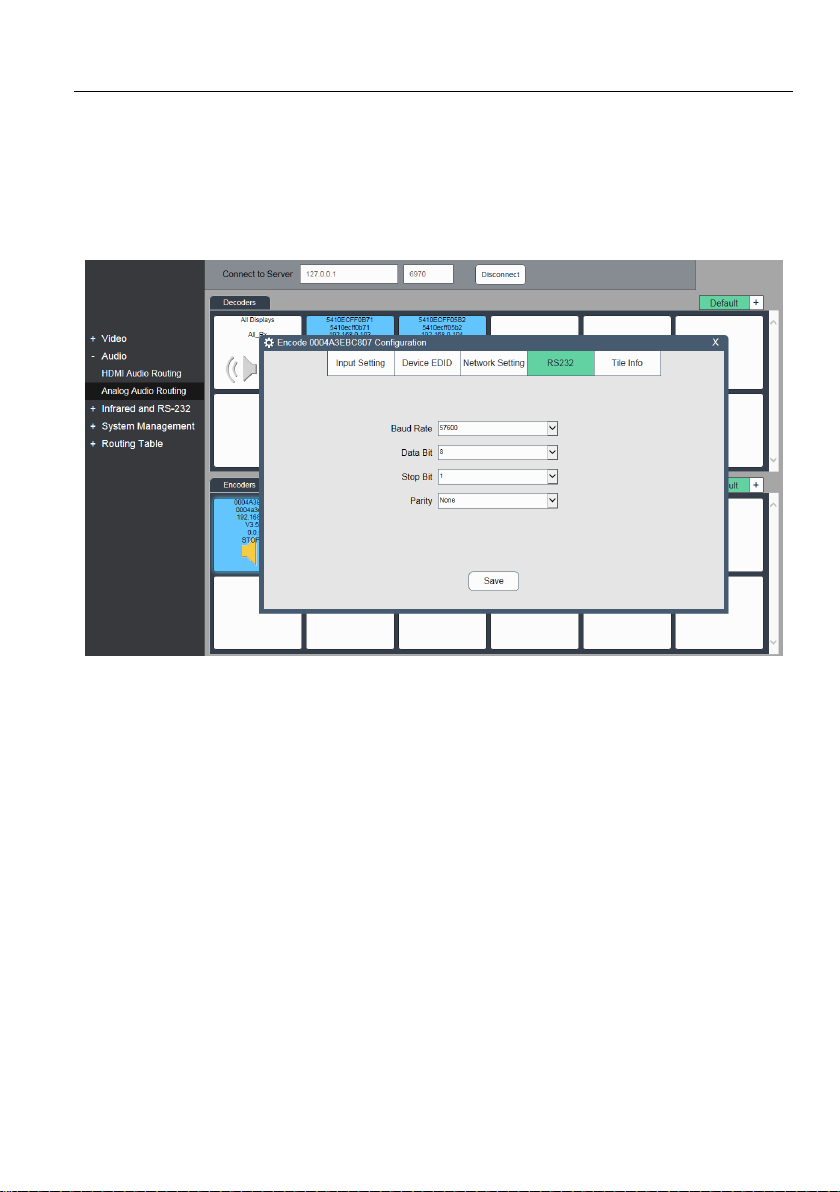
RS232
Use the RS232 tab to modify/edit the RS232 settings.
Select the desired port configuration (Baud Rate, Data Bit, Stop Bit and Parity). Click
the “Save” button to save the updated RS-232 configuration. New RS-232 settings are
kept until device is factory reset (forced to factory default settings).
38
Page 44
4K IP Streaming Extender
Tile Info
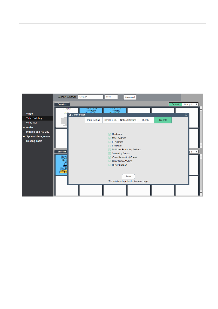
Use the Tile Info tab to select the type of information which needs to be displayed by
following the below steps:
5) Right click Encoder device tile.
6) Click the option “Setting”.
7) Select the Tile Info.
8) Select the type of information which needs to be displayed.
39
Page 45
4K IP Streaming Extender
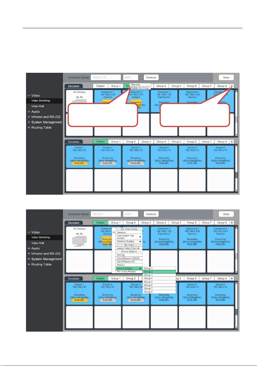
Click this icon to create
a new group.
Rename or Delete the
group.
5.10 Group management
a) The default includes all devices.
b) Click + to add new group (Maximum 8). Right mouse click over the Group tile to
rename or delete group.
c) User can add one device to multi group.
40
Page 46

4K IP Streaming Extender
5.11 System Management Tab
5.11.1 Device Firmware Upgrade
Device firmware updates are done over the network. The device has implemented a
special update protocol to update an individual device or consecutively update all
devices discovered on the local network with a single command.
The first step is to place this zip file in an update folder under the directory where the
Server is installed. The Server is then instructed to update devices from a selected file
archive.
Example of update folder location:
C:\blueriver_control-2.14.0.0\windowscygwin32\update
Follow the step by step procedure below to update the firmware:
1) If not already complete, copy the update file (*.apz) containing the firmware update
into the update folder.
2) By default, the update folder is located in the same directory as the Serve. If the
update folder does not exist, it is necessary create it.
3) The system automatically discover all devices currently active on the network.
4) Select the update file on the drop-down box.
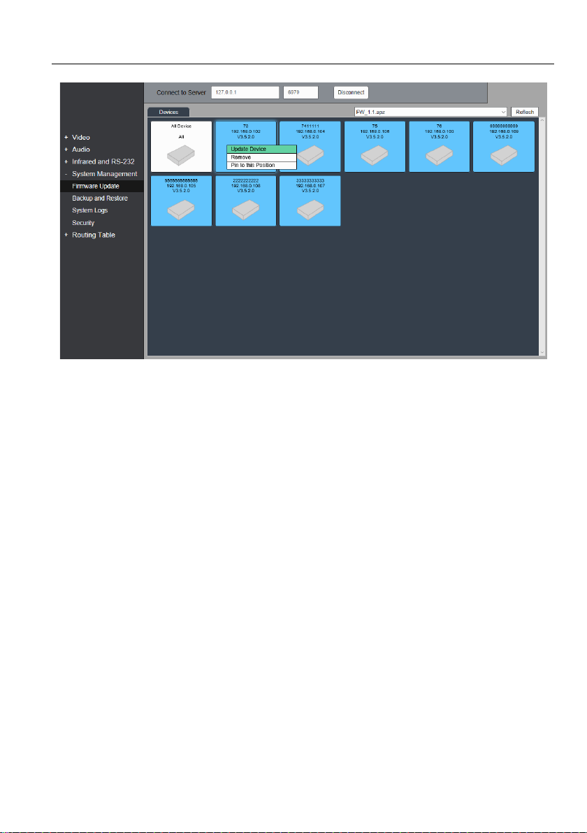
a) To trigger the upgrade of an individual device, right-click over its device tile and
select Update Device.
b) To update all the devices, right click on the Blue tile labeled All Devices and
select Update Device.
5) Start the device update. The device tiles will show the progress of the update.
6) When the firmware update completes, the devices will provide a message to
automatically initiate a reboot of all updated units.
41
Page 47
4K IP Streaming Extender
5.11.2 System Backup and Restore
The primary function of the tab is used to backup and restore system settings.
Currently available options includes:
Video routing
Wall setting and routing
HDMI Audio and analog audio routing
RS232 and IR routing
Device parameter setting
42
Page 48
4K IP Streaming Extender
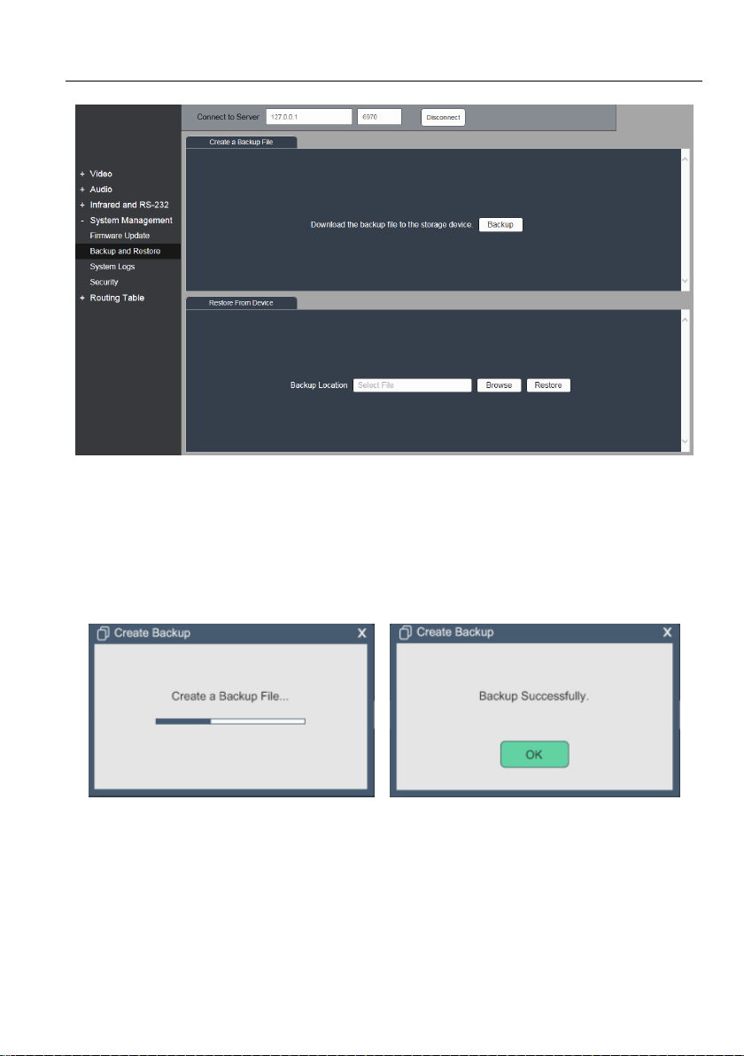
System Backup:
1) Click Backup.
2) Click Browse to select the destination path.
3) Type the backup file name to start backup.
43
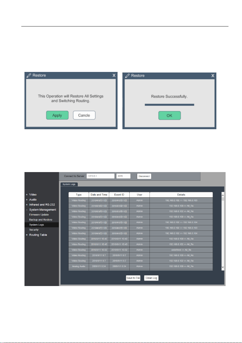
Page 49
4K IP Streaming Extender
System Restore:
1) Click Browse to select the file path.
2) Click Restore to start.
5.11.3 System Logs
Select the System Logs tab interface to enter the below section to inquiry the system
logs.
44
Page 50
4K IP Streaming Extender
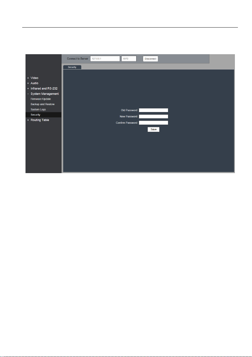
5.11.4 Security Setting
Select the Security tab to enter the below section to modify the password.
45
Page 51
4K IP Streaming Extender
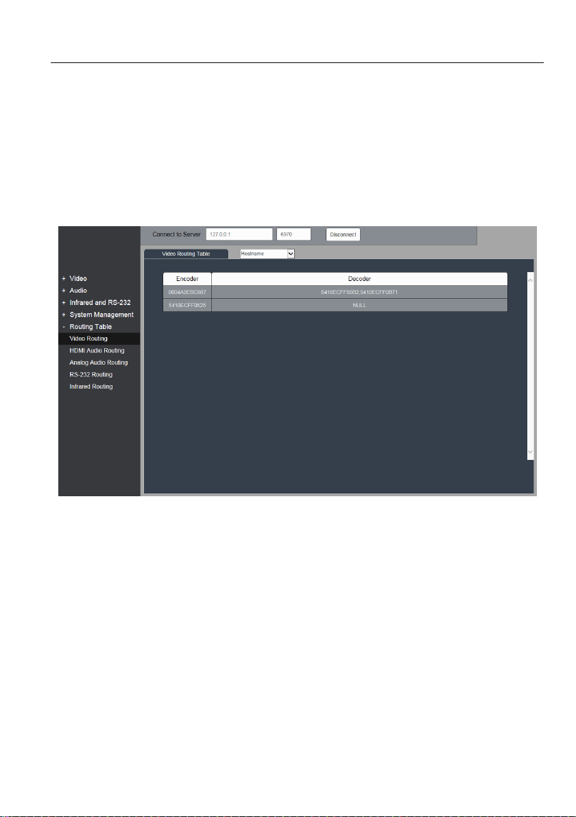
5.12 Routing Table
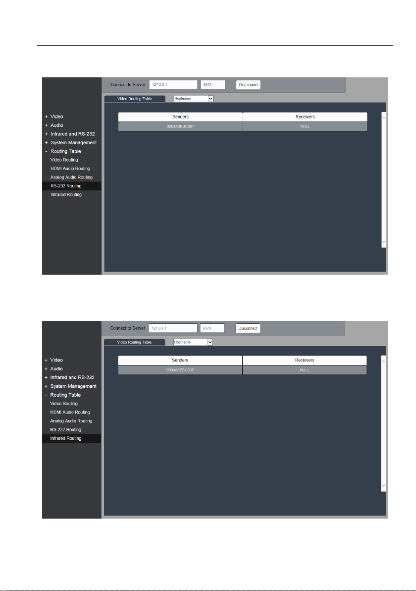
Routing table allows to inquiry the video routing, HDMI audio routing, analog audio
routing and RS232 routing status. Three display name options are available, including
Hostname, IP Address and MAC Address.
Video Routing Table:
46
Page 52
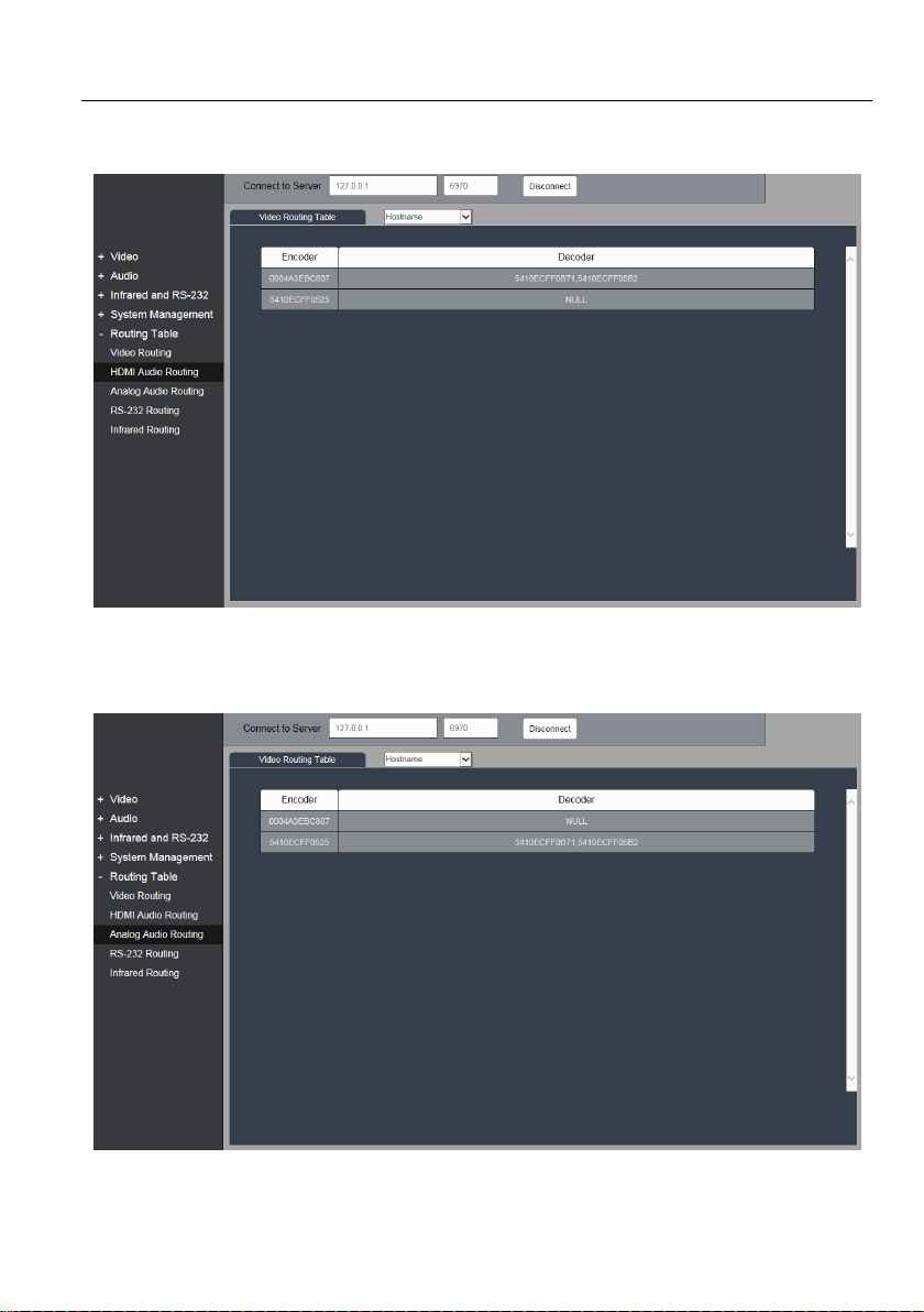
HDMI Audio Routing Table:
Analog Audio Routing Table:
4K IP Streaming Extender
47
Page 53
RS232 Routing Table:
Infrared Routing Table:
4K IP Streaming Extender
48
Page 54
6. Panel Drawing
LINK DPHDMI
HDMI IN
AUDIO IN
IR IN
RS232
Tx Rx
IR OUT DC 12V
ETHERNET
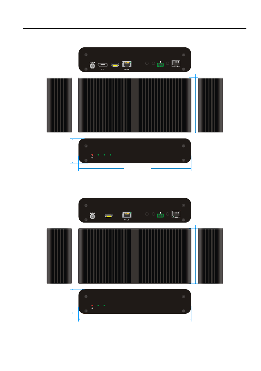
224.0 mm
4
9
.
2
m
m
1
1
0
.
0
m
m
LINK HDMI
HDMI OUT AUDIO OUT
IR IN
RS232
Tx Rx
IR OUT DC 12V
ETHERNET
224.0 mm
4
9
.
2
m
m
1
1
0
.
0
m
m
4K IP Streaming Extender
IPA100E-TX
IPA100D-RX
49
Page 55

4K IP Streaming Extender
7. Troubleshooting & Maintenance
1) If the GUI can’t detect any IPA100 extender, please confirm the following points:
Whether the IP address is configured correctly. Please ensure the IP of control
PC is set to the same network segment with the IPA100.
Whether there is an IP address conflict with other device in the same LAN.
Please make sure each device has a different IP address in the same LAN.
Power supply is normal. The IPA units is fully loaded with 12V 2A consumption.
Sometimes he GUI may not detect device when you set the video mode as Fast
Switch 2160P and equip with a 12V 1A power supply.
The connection cables are high-qualify (preferred Cat6a cable), and they are
linked successfully.
Confirm the switch is configured to enable IGMP snooping
2) If the Manager can detect the IPA100 extender, please confirm whether the video
source is selected correctly, and the connection cable is linked correctly.
Note: If your problem still remaining after following the above troubleshooting steps,
please contact your local dealer or distributor for further assistance.
50
Page 56

4K IP Streaming Extender
8. Customer Service
The return of a product to our Customer Service implies the full agreement of the terms
and conditions hereinafter. There terms and conditions may be changed without prior
notice.
1) Warranty
The limited warranty period of the product is fixed three years.
2) Scope
These terms and conditions of Customer Service apply to the customer service
provided for the products or any other items sold by authorized distributor only.
3) Warranty Exclusion
Warranty expiration.
Factory applied serial number has been altered or removed from the product.
Damage, deterioration or malfunction caused by:
Normal wear and tear.
Use of supplies or parts not meeting our specifications.
No certificate or invoice as the proof of warranty.
The product model showed on the warranty card does not match with the
model of the product for repairing or had been altered.
Damage caused by force majeure.
Servicing not authorized by distributor.
Any other causes which does not relate to a product defect.
Shipping fees, installation or labor charges for installation or setup of the
product.
4) Documentation:
Customer Service will accept defective product(s) in the scope of warranty
coverage at the sole condition that the defeat has been clearly defined, and upon
reception of the documents or copy of invoice, indicating the date of purchase, the
type of product, the serial number, and the name of distributor.
Remarks: Please contact your local distributor for further assistance or solutions.
51
 Loading...