

Page 1
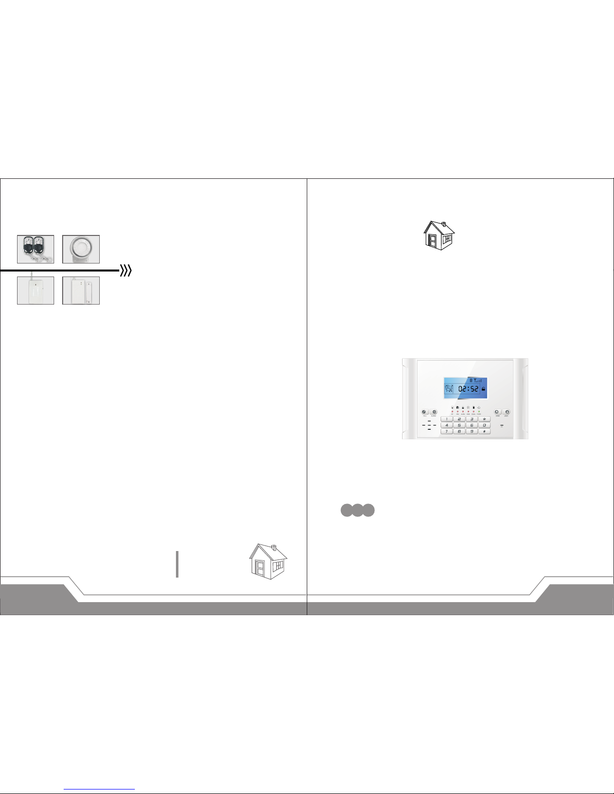
Alarm System
Auto-dial
MOBILE CALL
GSM Alarm System
For a better understanding of this product, please read this user
manual thoroughly before using it.
Profile
Auto-dial
Alarm System
2012.11.V2 .0
Page 2

CONTENTS
I.Function Instruction………………… ……………… ………………1
II.Alarm Host Diagram ……………………………… ……… 2
Alarm Panel front schematic diagram… …………………… ……………… 2
LCD display………………………… ………………………………………………… 2
Alarm Panel back schematic diagram…………… …………… …………… 3
Wired terminal block…… ……………… …………… ……………… ……………3
III.Door sensor……………………… ………………………………………… ……4
IV.Wireless PIR detector……… …………………… ………………… ……… 5
V.Function Settings ……………………………………………………………… 5
1.Initialization………………… ………………………… …………………………… 5
2.Enter Settings……………………………………………………………………… 5
3.Exit Settings…………………………………………………………………………6
4.Factory Reset……………………………… ………………………………………6
5.Coding of Remote Controller…………… ……………………………… ……6
6.Delete Remote Controller………………………………………………………7
7.Coding of Defense Zone…… ………………… …………………… …………7
8.Delete Defense Zone…………………… ………………………………………8
9.Change Password……… …………… …………… …………… …………… …8
10.Clock Setting…… …………… …………… …………… …………… …………9
11.Timing Settings……… …………… ……………… …………… …………… …9
12.Wireless Transmission Control……………………………………………11
13.Wireless Siren Coding Encryption……… …………………………… …11
14.Time Setting of Out Arm Delay …… ……………… ……………… ……12
15.Time Setting of Alarm Delay…………………………… …………………12
16.Alarm Number Setting………… ……………………… ……………………12
17.Delete Phone Number…………… …………………………… ……………13
…………
……………………
CONTENTS
18.SMS Receiving Number Setting…………… …………………………13
19.Delete SMS Receiving Number… ……………… ……………… ……14
20.SMS Notification for Arm/Disarm………… ……… ……… ………… 14
21.Defense Zone Programming……………………………………………14
22.Home Arm Defense Zone Setting……… ……………… ……………15
23.Voice Recording………………… ………………… ………………… ……16
24.Arm/ Disarm Siren Sound Setting… ………………… ………………16
25.Siren Setting in “Emergency Help” mode……… …………… ……17
26.Arm/ Disarm Voice Prompt………………………………………………17
27.Voice Prompt for All Settings……………………………………………17
28.IMEI Checking………… …………………… ……………………… ………18
VI.Operation Instructions……… ………………… ……………… ………18
1.System status. There are 4 status as following……………………18
2.Remote Controller Operation…… ………………… ………………… …18
3.Home Arm…………………………… ………………………………… ………18
4.Out Arm………………… ………………… ………………… ………………… 19
5.Disarm………………………… ………………………………………… ………19
6.Answer Alarm Call……………………………………………………………20
7.Remote Control………… ………………… ………………… ………………21
8.Emergency Help…… ……… ………… ………… ……… ………… ………21
9.System Dialing Function… ………… ……… ………… ………… ………21
10.Alarming Record Checking… ……… ………… ……… ………… ……21
11.GSM Signal Checking……………… ……………… ……………… ……22
VII.Technical Parameters…………… ………… ………… …………… …23
VIII.Components List…… ………… ……… ………… ………… ………… 24
IVV.Care and Maintenance… ……… ………… ……… ………… ……… 27
Page 3
1
Features
6 wired and 99 wireless defense zones;
LCD screen with time clock display;
Voice prompt for all operations;
3 groups of timely arm and disarm;
Can store 6 phone numbers: when alarming, system will
make alarm call to these numbers automatically;
Can store 3 SMS numbers: when alarming, system will send
alarming SMS automatically;
10-second automatic message recording;
Built-in artificial intelligent digital voice announcer;
Built-in artificial intelligent English message;
Users can make calls by using keypad on alarm panel, just
like a telephone;
One-key-control function: Out Arm, Home Arm, Remote Arm;
Arm/ disarm by SMS or call remotely;
SOS, fire, gas, door, hall, window, balcony, and boundary
places alarm;
Real-time, delay, 24 hours , bypas s defense zones
programming function;
Wirel ess cod ing : easy to add ad ditio nal wirele ss
accessories;
Remote control Arm, Disarm, Monitor, and Intercom by
phone;
SMS alert for power failure or recovery;
Built-in LI rechargeable battery: make alarm when power off.
[Function Instruction]
In order to make the main unit get the wireless signal well for all
wireless accessories, please put the alarm host at the central place of
your defense area. Make sure it’s away from large metal objects and
household appliances which may cause high frequency interference,
as well as barriers such as reinforced concrete wall or fire door, etc.
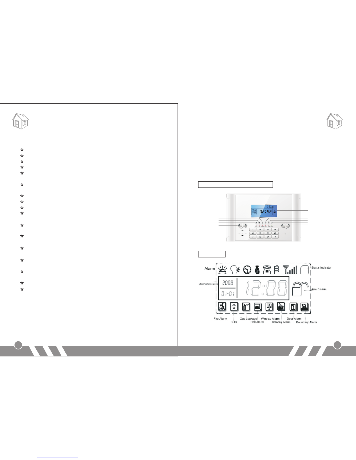
Alarm Panel front schematic diagram:
LCD display:
[Alarm Host Diagram]
Installation
Ala rm Indi cator
2
Away Ar m Indic ator
Set ting In dicat or
Cal l Out
Eme rgenc y
Spe aker
Hom e Arm I ndica tor
Sig nal Ind icato r
Pow er Indi cator
Out Ar m
Hom e Arm
Mic
LCD S creen
GSM
Page 4
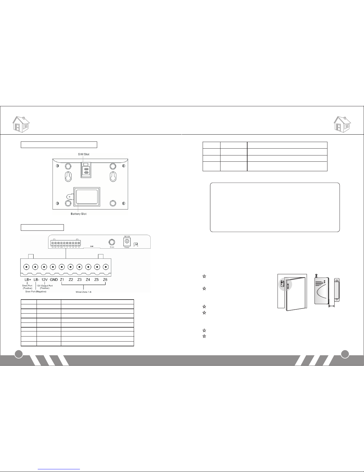
Alarm Panel back schematic diagram:
Wired terminal block:
Installation Installation
3
4
Note:
1.“LB-” and “LB+” are to connect external speaker. If you think
the internal speaker is not loud enough, please contact us for
professional speakers.
2.Connect one cable of the wired sensor to GND and the other
to “Z1/Z2/Z3…/Z6”.
3.Please pay attention to the siren connection. Do not mix the
two cables together when connecting. Otherwise, it will
damage the transistor in the main panel.
[Door sensor]
Door sensors are used for detecting the status of open and close of
windows and doors. It will detect it and send the signal to main panel.
Tear apart the double -side
adhesive tape on the magnet
an d the trans mi tter. Th en
adhere them to the appropriate
position.
Magnet should be near to the
side of transmitter with indicator.
The two should align with eachother and the distance should not
exceed 10mm.
Please plug out the antenna for better signal.
If the low-power indicator is on, please change the battery.
1
LB+ Positive of speaker (red cable)
2 LB- Negative of speaker (black cable)
3 12V 12V Output Port (Positive)
4 GND Ground
5 Zone 1 Wired sensor 1: support both NO and NC
6 Zone 2 Wired sensor 2: support both NO and NC
7 Zone 3 Wired sensor 3: support both NO and NC
8 Zone 4 Wired sensor 4: support both NO and NC
9 Zone 5 Wired sensor 5: support both NO and NC
10 Zone 6 Wired sensor 6: support both NO and NC
1
SIM Put SIM card in this card slot
2 Siren Plug in siren connector
3 Power Connect to the external power supply
4 Switch Switch for backup battery. Turn it on after
power on.
Less than 10mm
Page 5
Functions Settings
5
6
[Wireless PIR detector]
PIR detectors are used to detect the movement within a certain range.
Fix the adjustment bracket on
the wall with the provided
s cre ws and a tt a c h t h e
detector to the bracket. It is
recommended to mount it at a
height of 2-2.2m above the
floor.
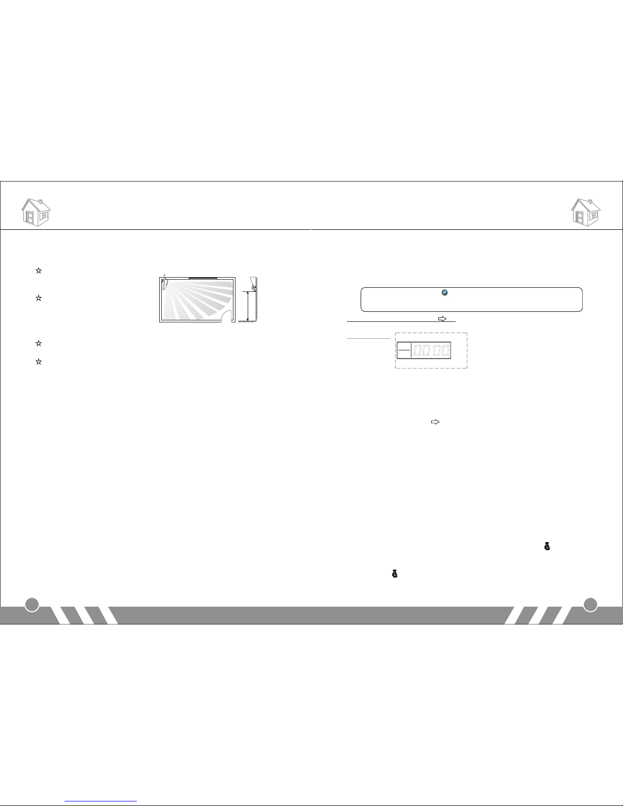
Effect of the PIR detection is best when the detection direction is in
90° angle with the walking direction of the intruder. Choose the most
suitable installation place and angle according to actual situation and
taking the following installation diagram as reference to ensure the
detection effect is best.
Please do not fix it under direct sunlight or other strong lights and
also keep it away from places with frequent strong air stream.
If the low-power indicator is on, please change the battery.
[Function Settings]
1.Initialization
Please insert SIM card and plug in power adaptor, and then power on
the system, all the LED lights will be on for 2 seconds and you will hear
a long beep; the system comes into initialization. After the time clock
displays on the LCD screen, the [G M] starts flashing and the main
unit starts to detect the G M network until a long beep. Then the
[ SM] indicator goes out indicating the system comes into disarm
status.
Finally, turn on the backup battery switch.
2.Enter Settings
In the state of disarm, input 4-digit password by the keypad on the
main unit and press [#] button to confirm. You will hear a voice prompt:
please enter instruction. At the same time, [SET] indicator is on without
flashing and [0000] displays on the screen, indicating the system
enters setting status. You can perform different settings repeatedly as
S
S
G
long as the system keeps in setting status. The system will exit
setting mode and return to disarm status if you don’t press any
keypad button for 40 seconds.
Note:
In setting status, press can delete the numbers input.
The system default password is [8888].
Operating method: [XXXX] [#]
X indicates the new 4-digit password.
LCD display:
3.Exit Settings
Press [ * ] and [#] buttons, the main unit emits a long beep and exits
settings. The [SET] indicator goes out and the system returns to
disarm state.
Operating method: 【*】 【#】
4.Factory Reset
In disarm status, use keypad to input [95175308246] and press [#] to
confirm, all the LED indicators will be on for 2 seconds and you will
hear a long beep. The main unit gets all its settings cleared and
restores to its factory settings successfully.
Operating method: [95175308246] + [#]
5.Coding of Remote Controller
Extra remote controller has to be code to the alarm host in order to
perform normally. The one in the standard package has been coded.
In setup state, use keypad to input [20], input the remote controller
number [1~8], and then press [#] to confirm. The main unit emits a
long beep and you will hear “remote control coding”. The [ ] indicator
is on without flashing; press any button on the wireless remote
controller, the main unit makes a long beep and you will hear “coding
completed”, [ ] indicator goes out, indicating the remote controller
succeeds in coding.
Installation
door
2m-2.2m
10-30℃
Window
Page 6
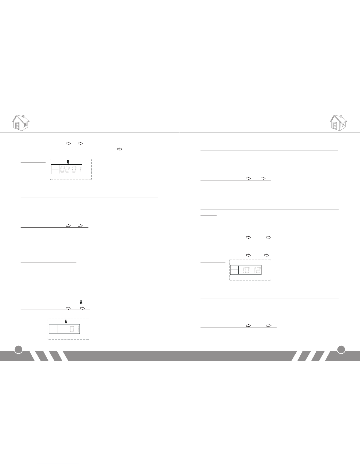
Operating method: [20] [A] [#]
A indicates: 1~8 remote controllers number. You can add maximum 8
remote controllers.
LCD display:
6.Delete Remote Controller
The remote controller can’t control the main unit after it’s deleted.
In setup state, use keypad to input [21], then input the remote
controller number [1-8], and then press [#] to confirm. The main unit
emits a long beep and the [Signal] indicator flickers once. You will hear
a voice prompt “delete completed”.
Operating method: [21] [A] [#]
A indicates: 1~8 remote controllers number.
7.Coding of Defense Zone
Wireless detectors have to be coded to the main unit in order to
trigger it alarm. The wireless PIR and door sensor in the standard
package have been coded.
In setup state, use keypad to input [23], input the defense zone
number you want to code [01~99], and then input [#] to confirm. The
main unit emits a long beep and the corresponding defense zone is
displayed on the screen. You will hear a voice prompt “detector
coding”. Then trigger a wireless detector to emit a wireless signal; after
receiving the signal, the main unit makes a long beep, and you will
hear “coding completed”, the [ ] indicator goes out at the same time.
Operating method: [23] [XX] [#]
XX indicates: 01 ~99 defense zones number
LCD display:
Functions Settings Functions Settings
7
8
8.Delete Defense Zone
The wireless detector can’t control the main unit after it’s deleted.
In setup state, use keypad to input [24], then input the defense zone
number you want to delete [01~99], and then input [#] to confirm. The
main unit emits a long beep and the defense zone indicator flickers
once. You will hear a voice prompt “delete completed”.
Operating method: [24] [XX] [#]
XX indicates: 01 ~99 defense zones number
9.Change Password
1) Change Operation Password
Operation password is the password used to disarm or remote
control.
In setup status, use keypad to input [30], then input the 4-digit new
password, and then press [#] to confirm. The main unit will make a
long beep and you will hear a voice prompt “setting completed”.
Operating method: [30] [XXXX] [#]
XXXX indicates: the new 4-digit password
For example: change the system password to 1012
Operating method: [30] [1012] [#]
LCD display:
2) Change Program Password
Program password is the password you should input in order to
setup the system.
In setup status, use keypad to input [31], then input the 4-digit new
password, and then press [#] to confirm. The main unit will make a
long beep and you will hear a voice prompt “setting completed”.
Operating method: [31] [XXXX] [#]
XXXX indicates: the new 4-digit password
For example: change the system password to 2846
Page 7
Operating method: [31] [2846] [#]
LCD display:
Note:
the operation password and the programming password can not
be set as the same number.
10.Clock Setting
In setup status, use keypad to input [32], then input the last 2 digits
[AA] of the present year, the two digits [BB] of the month, the two
digits [CC] of the date, the two digits [DD] of the hour (24-hour
system), the two digits [EE] of the minute, the two digits [FF] of the
second, and finally enter [#] to confirm. You will hear a long beep and
a voice prompt “setting completed”.
Operating method: [32] [AA] [BB] [CC] [DD] [EE] [FF] [#]
AA indicates: the last 2 digits of the present year
BB indicates: the 2 digits of the present month
CC indicates: the 2 digits of the present date
DD indicates: the 2 digits of the present hour
EE indicates: the 2 digits of the present minute
FF indicates: the 2 digits of the present second
For example: set the time as 15:35:40, Oct. 1st, 2009
Operating method: [32] [09] [10] [01] [15] [35] [40] [#]
11.Timing Settings
1) Timely Arm
In setup status, use keypad to input [33~35], then input the hour [AA]
and minute [BB] of the time you want to set to arm, and finally input
[#] to confirm. You will hear a long beep and a voice prompt “setting
completed”.
Operating method: [XX] [AA] [BB] [#]
10
XX indicates: the address code 33, 34, 35 of the timely arming
AA indicates: the hour of the setting time
BB indicates: the minute of the setting time
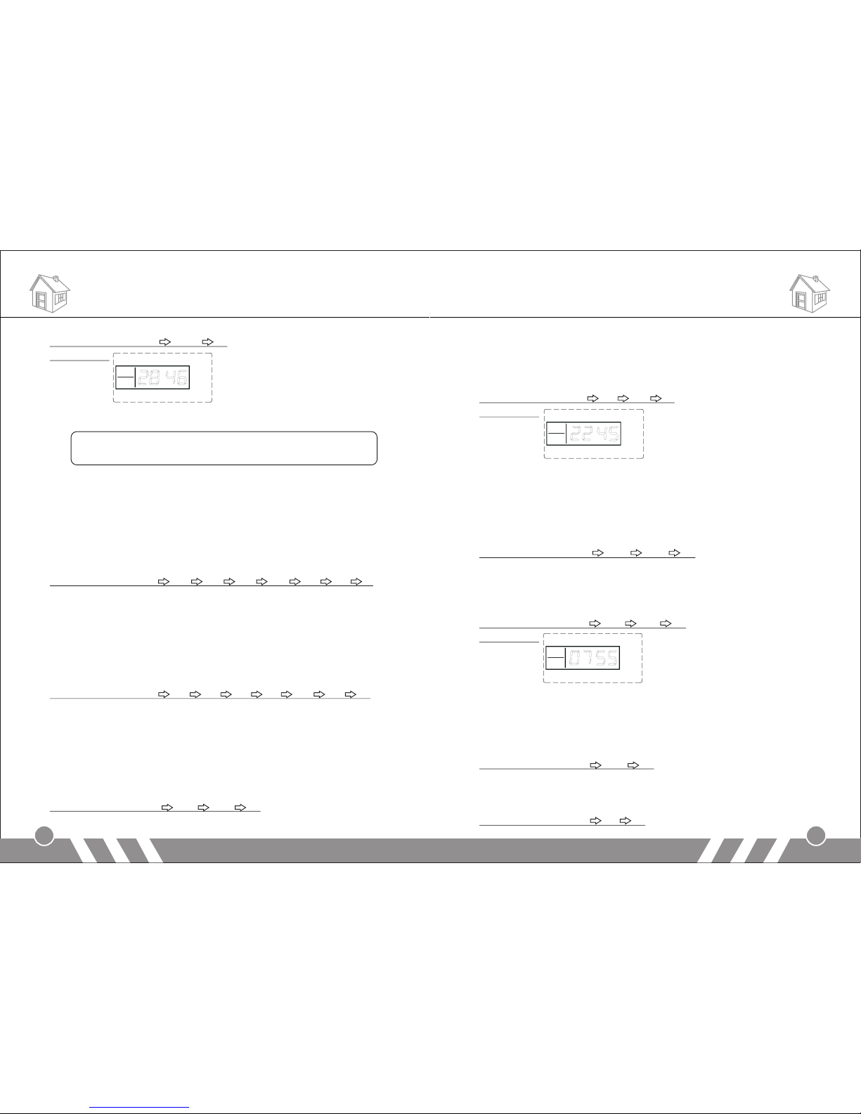
For example: set the arm time as 45’ 10pm
Operating method: [33] [22] [45] [#]
LCD display:
2) Timely Disarm
In setup status, use keypad to input [36~38], then input the hour [AA]
and minute [BB] of the time you want to set to disarm, and finally input
[#] to confirm. You will hear a long beep and a voice prompt “setting
completed”.
Operating method: [XX] [AA] [BB] [#]
XX indicates: the address code 36, 37, 38 of the timely disarming
AA indicates: the hour of the setting time
BB indicates: the minute of the setting time
For example: set the arm time as 55’ 7am
Operating method: [33] [22] [45] [#]
LCD display:
3) Timing Control
In setup status, use keypad to input [39], then input the number
indicating turning on timely arm/ disarm [1/0], and then input [#] to
confirm. You will hear a long beep and a voice prompt “setting
completed”. The factory default is off.
Operating method: [39] [0/1] [#]
0: turn off the function of timely arm/ disarm
1: turn on the function of timely arm/ disarm
For example: turn on the function of timely arm/ disarm
Operating method: [39] [1] [#]
Functions Settings Functions Settings
9
Page 8
12.Wireless Transmission Control
This function is optional. We can make the control panel with built-in
transmitter, so that it would be more convenient to work with wireless
siren. Only the panel with built-in transmitter has this function.
In setup status, use keypad to input [41], then input the number [1/0],
and then input [#] to confirm. You will hear a long beep and a voice
prompt “setting completed”. The factory default is off.
Operating method: [41] [0/1] [#]
0: turn off the function of wireless transmission
1: turn on the function of wireless transmission
For example: turn on the function of wireless transmission
Operating method: [41] [1] [#]
LCD display:
Note:
after activating this function, do as follows to set the wireless
siren with the alarm panel.
Input [411#], and then make the siren you want to set into
coding status, finally press [0#] on the panel.
Pressing [0#] means the panel will make coding signal to the
siren, this signal will last for 3 seconds. So please make sure
the siren is in coding status during this 3-second period.
13.Wireless Siren Coding Encryption
Only the panel with built-in transmitter has this function.
The signal used to code with the wireless siren is sent from the internal
transmitter of the main panel. The signal codes of this product from our
company are the same. If you and your neighbor both are using this
product, the alarm signal from your neighbor may cause your siren sound.
11
So it is recommended to encrypt the wireless siren to avoid the
interference.
In setup status, use keypad to input [43], then input the number [01] ~
[99], and then input [#] to confirm. You will hear a long beep and a
voice prompt “setting completed”.
Operating method: [43] [A] [#]
A indicates: the code number 01~99
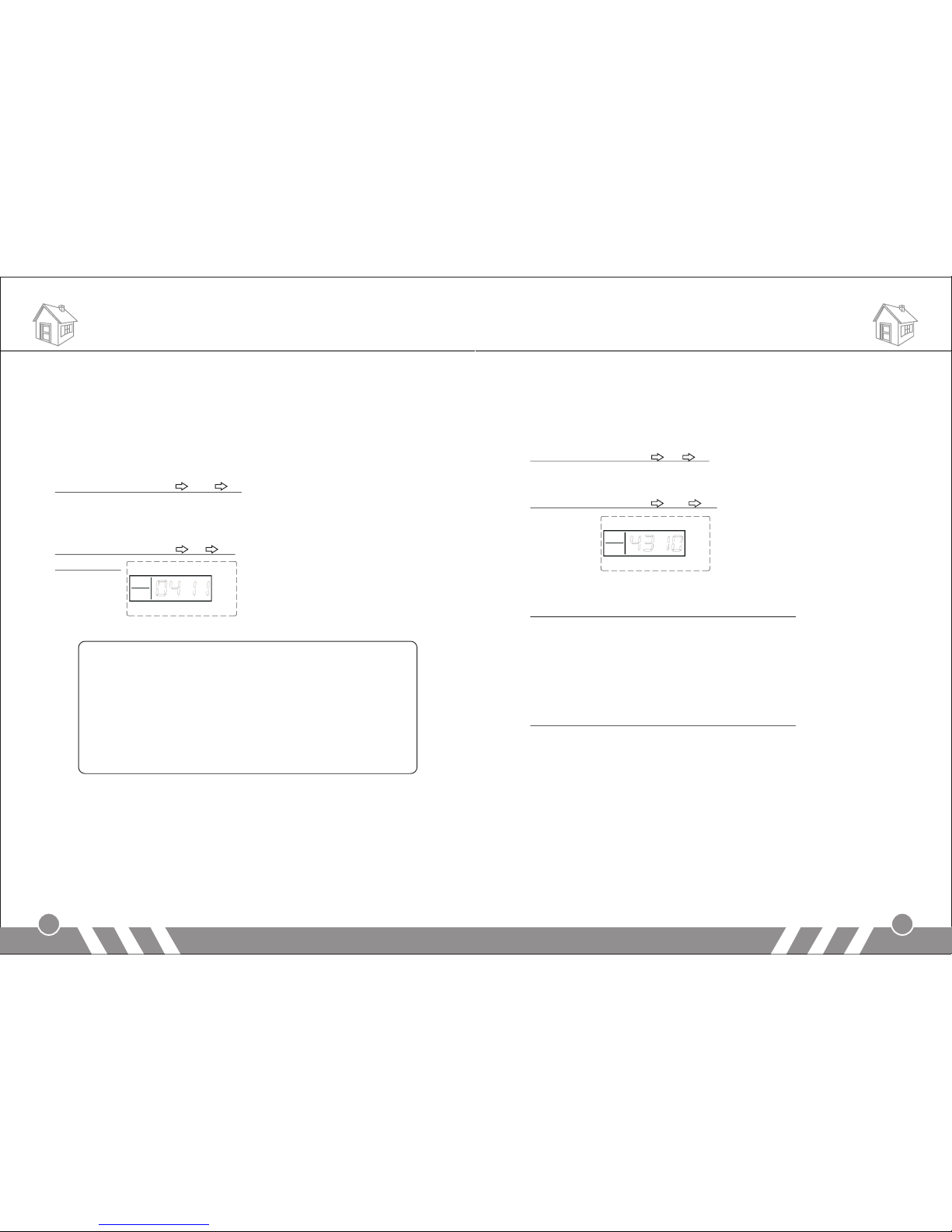
For example: set the wireless coding number as 10
Operating method: [43] [10] [#]
LCD display:
14.Time Setting of Out Arm Delay (Default: 60 sec)
In setup state, input the command: [44] + [XX] +[ # ]
XX indicates: the delay time of out arm; XX= 01-99: 1 sec to 99 sec
Note: The setting is effective only with the panel keyboard operation.
The operation by remote controller or SMS is immediate arm without
delay.
15.Time Setting of Alarm Delay (Default: 40 sec)
In setup state, input the command: [45] + [XX] + [#]
XX indicates: the delay time of alarm; XX= 01-99: 1 sec to 99 sec
Note: The setting is effective only when a zone is set as Alarm Delay
Zone.
Note: Before the system enters arm or alarm status it will emit a "Di"
sound per second.
16.Alarm Number Setting
In setup state, input [51] ~ [56], then input the voice alarm-receiving
number (mobile number or telephone number), and then press [#] to
confirm. The main unit will make a long beep, the [Signal] indicator will
flicker once, and you will hear “setting completed”, which indicate voice
alarm-receiving number is set successfully.
12
Functions Settings Functions Settings
Page 9
Operating method: [XX] [YY…YY] [#]
XX indicates: the 1- 6 alarming user number [51] ~ [56]
YY…YY indicates: voice alarm-receiving phone number
For example: set 13811111111 as the first voice call number
Operating method: [51] [13811111111] [#]
LCD display:
17.Delete Phone Number
In setup state, input [51] ~ [56], and then press [#] to confirm, the main
unit will make a long beep and the [Signal] indicator will flicker once
and you will hear “delete completed”, which indicate the alarming user
number is deleted successfully.
Operating method: [XX] [#]
XX indicates: the 1- 6 alarming user number [51] ~ [56]
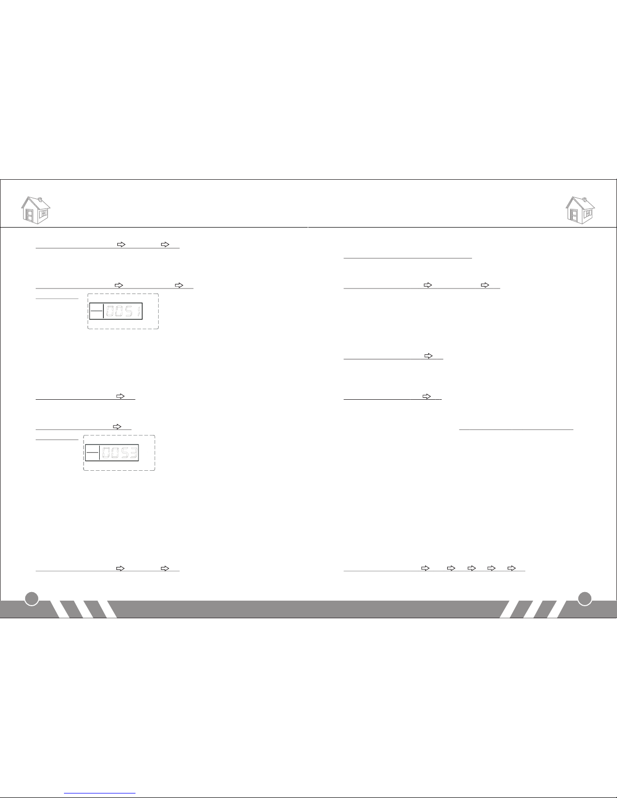
For example: Delete the third alarming user number from the system.
Operating method: [53] [#]
LCD display:
18.SMS Receiving Number Setting
SMS Receiving number means when system is alarming, it will only
send SMS to this mobile number. You can set maximum 3 SMS
numbers.
In setup state, input [57] ~ [59], then input the SMS receiving number,
and then press [#] button to confirm. The main unit will make a beep,
the [Signal] indicator will flicker once and you will hear “setting
completed”, which indicate setup successfully.
Operating method: [XX] [YY…YY] [#]
XX indicates: address codes of message-receiving numbers from the
first group to the third group [57] ~ [59]
YY…YY indicates: the SMS receiving number
For example: setup 13822222222 as the first SMS receiving number
Operating method: [57] [138222222] [#]
19.Delete SMS Receiving Number
In setup state, use keypad to input [57] ~ [59], and then press [#]
button to confirm. The main unit will make a beep, the [Signal] indicator
will flicker once and you will hear “delete completed”, which indicate
SMS number is deleted successfully.
Operating method: [XX] [#]
XX indicates: address codes of message-receiving numbers from the
first group to the third group [57] ~ [59]
For example: delete the first SMS user number from the system
Operating method: [57] [#]
20.SMS Notification for Arm/Disarm (Default: OFF)
In setup state, input the command [77] + [1/ 0] + [#] (1: ON, 0: OFF)
After starting this function, the system can send SMS to three SMS
receiving numbers (57~59 as mentioned above) when the system
enters arm/ disarm status through wireless remote controllers or its
panel keyboard operation.
21.Defense Zone Programming
If you want to change the alarm attribute of defense zone, such as turn
off the siren when system alarms, you can do it by defense zone
programming. In setup state, first input [60], then the defense zone
number [01~99], then input defense zone type [1~4], then input alarm
type [1~8], and then select siren on/off [0/1], at last press [#] to
confirm. You will hear the main unit emit a long beep and a voice
prompt “setting completed”.
Operating method: [60] [AA] [B] [C] [D] [#]
13
14
Functions Settings Functions Settings
Page 10
AA: defense zone number [01~99] means zone 1 to zone 99;
B: defense zone type
[1]: real-time defense zone [2]: 40 seconds delay defense zone
[3]: 24 hours defense zone [4]: bypass defense zone
C: alarm type
[1] SOS Alarm [2] Fire Alarm [3] Gas Leak Alarm
[4] Door Alarm [5] Hall Alarm [6] Window Alarm
[7] Balcony Alarm [8] Boundary Alarm
After setting the alarm type, the corresponding alarm type icon will be
shown on the LCD screen when alarming. And you will hear the alarm
type voice prompt when answering the alarm call.
D: siren ON/OFF: [0] OFF, [1] ON
For example: set defense zone 12 to be 24-hour, fire alarm and siren
on
Operating method: [60] [12] [3] [2] [1] [#]
22.Home Arm Defense Zone Setting
Home arm defense: sometimes (for example, when you are at home),
you want some of the sensors work while some do not, you can do this
setting.
In setup state, use keypad to input [61], then choose the
corresponding defense zone number [01~99], then choose [Home
Arm], and then choose whether alarm [0/1] button, and finally press [#]
to confirm. The main unit will make a long beep and a voice prompt
“setting completed”.
Operating method: [61] [XX] [A] [#]
XX indicates: [01~99] is defense zone 1 to defense zone 99
A indicates: [0] no alarm under home arm status even the sensor is
triggered
[1] alarm under home arm status
Example: set sensor in defense zone 10 make alarm under home arm
status
Operation:【61】 【10】 【1】 【#】
After this setting, when you “home arm” the system, sensor in defense
zone 10 will work normally.
Example: set sensor in defense zone 55 not make alarm even when
it's triggered under home arm status
Operation:【61】 【55】 【0】 【#】
After this setting, when you “home arm” the system, sensor in defense
zone 55 will not work.
23.Voice Recording
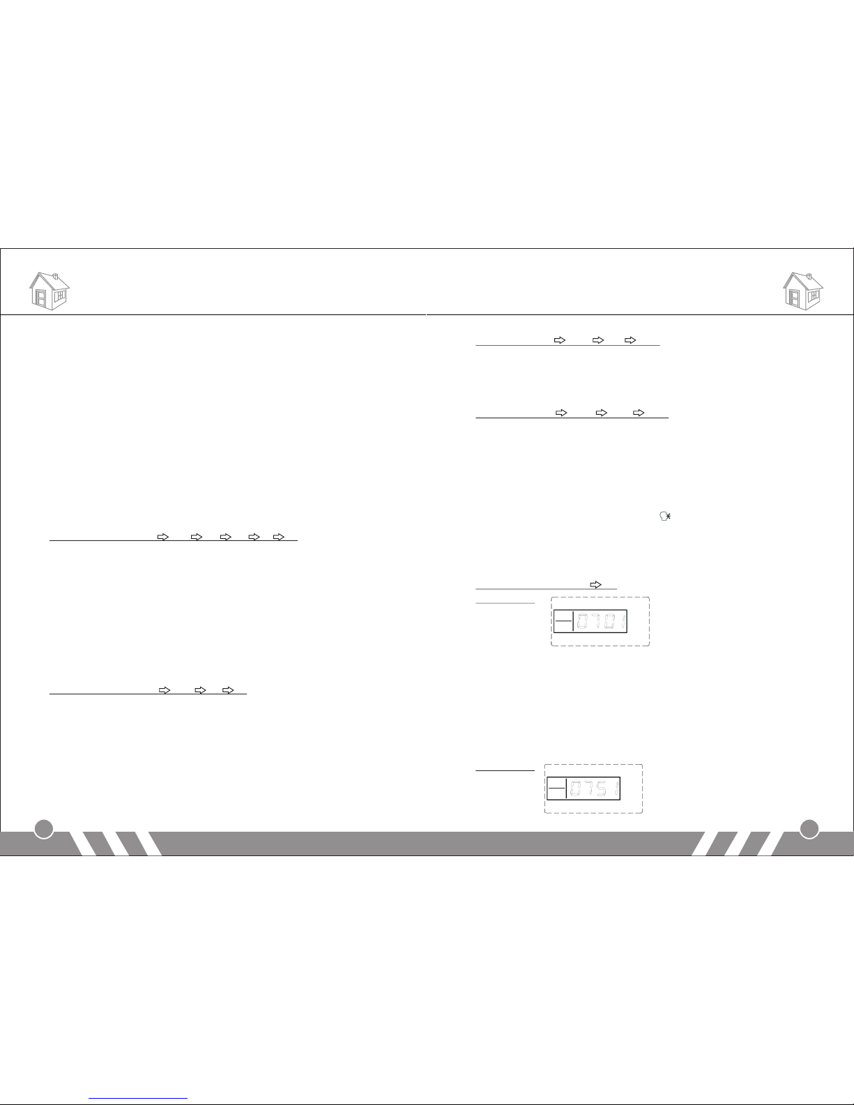
In setup state, use keypad to input [701], and then press [#] to confirm.
The main unit will emit a beep and the [ ] indicator is on, and after 10
seconds countdown, recording starts: record at 30cm away from the
main unit with moderate tone; 10 seconds later, the main unit will make
a beep indicating the recording stops and the recorded voice will
replay.
Operating method: [701] [#]
LCD display:
24.Arm/ Disarm Siren Sound Setting
After you activate this function, when you arm the system, the external
siren will sound one short beep; and when you disarm it, there will be
two short beeps.
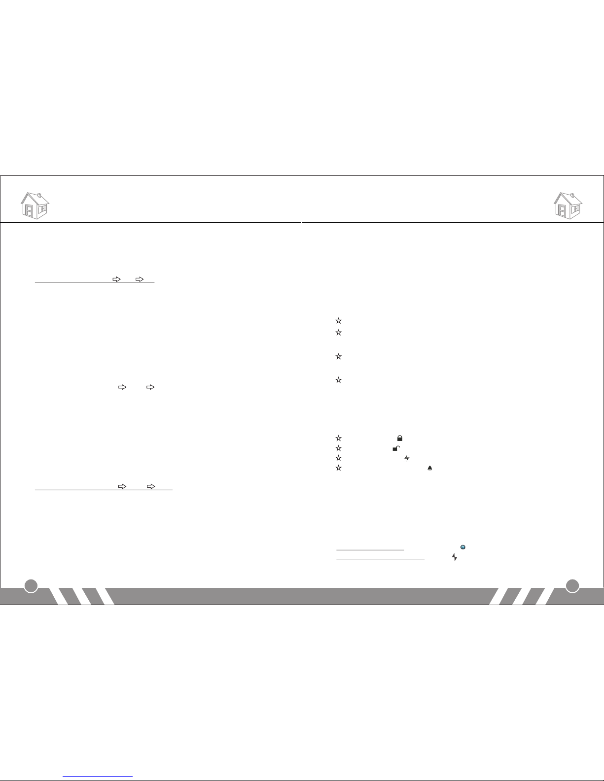
In setting status, use keypad to input [75], then [0/1] and finally press
[#] to confirm; voice prompts: setting completed, please enter
instruction”.
LCD display:
15
16
Functions Settings Functions Settings
Page 11
25.Siren Setting in “Emergency Help” mode
In setup state, use keypad to input [76], and then [1/0], finally press [#]
to confirm. The main unit will make a long beep and a voice prompt
“setting completed”.
Operating method: [76] [A] [#]
A indicates: [0]: siren off in “Emergency Help” mode
[1]: siren on in “Emergency Help” mode
System default: [0] siren off
26.Arm/ Disarm Voice Prompt
This product has this function: when you arm/ disarm it, it will give
voice prompt “system armed/ disarmed”. You can deactivate it if you do
not need.
In setting status, first input [83], then [0/1] and finally press [#] to
confirm; voice prompts: setting completed, please enter instruction.
Operating method:【83】 【A】 【#】
A indicates: [1]: activate voice prompt for arm/ disarm (factory default)
[0]: deactivate voice prompt for arm/ disarm
.
27.Voice Prompt for All Settings
For above settings, you could hear the voice prompt such as “setting
completed, please enter instruction”, “delete completed”. You can
deactivate the voice if you do not need them.
In setting status, first input [84], then [0/1] and finally press [#] to
confirm; voice prompts: setting completed, please enter instruction.
Operating method:【84】 【A】 【#】
A indicates: [1]: activate voice prompt for arm/ disarm (factory default)
[0]: deactivate voice prompt for arm/ disarm
Note: after you deactivate this function, all the voice including arm/
disarm voice would not work.
28.IMEI Checking
In setting status, first input [88] and then press [#] to confirm. The 15digit IMEI code will be displayed on the screen. It will display 4 digits
each time.
[Operation Instructions]
1.System status. There are 4 status as following:
Arm: defense zone 1~99 will alarm when detectors are triggered
Home Arm: in arm status, the defense zone which is set as [Home
Arm] will alarm when detectors are triggered.
Disarm: defense zone 1~99 will not alarm when detector triggered
(except 24 hours defense zone)
System setup status: In this status, all defense zones will not alarm
when detectors are triggered.
2.Remote Controller Operation
Users can use remote controller to set system as Out Arm, Home Arm,
Emergency Alarm, Real-time Disarm and etc.
Out Arm: Press button
Disarm: Press button
Home Arm: Press button
Emergency Alarm: Press button, system will alarm at once.
3.Home Arm
It means, for the safety, while somebody is at home, you need to
enable the peripheral door, window, balcony and boundary detectors of
the alarm system while prevent from triggering the indoor detectors,
which may cause improper warning; then, you shall select Arm at
Home, let just part of the detectors work and disable the other parts.
Main Unit Operation: Press [At Home ] button on keypad
Remote Control Operation: Press [ ] button on remote controller
17
Operating Instructions Operating Instructions
18
Page 12
LCD display:
4.Out Arm
It means to guard all around your house while everyone is going out;
all the detectors of the host are always working; when the detector is
triggered by detecting source (anti-theft, fire prevention, gas leak, etc.),
the alarm system will sound the alarm.
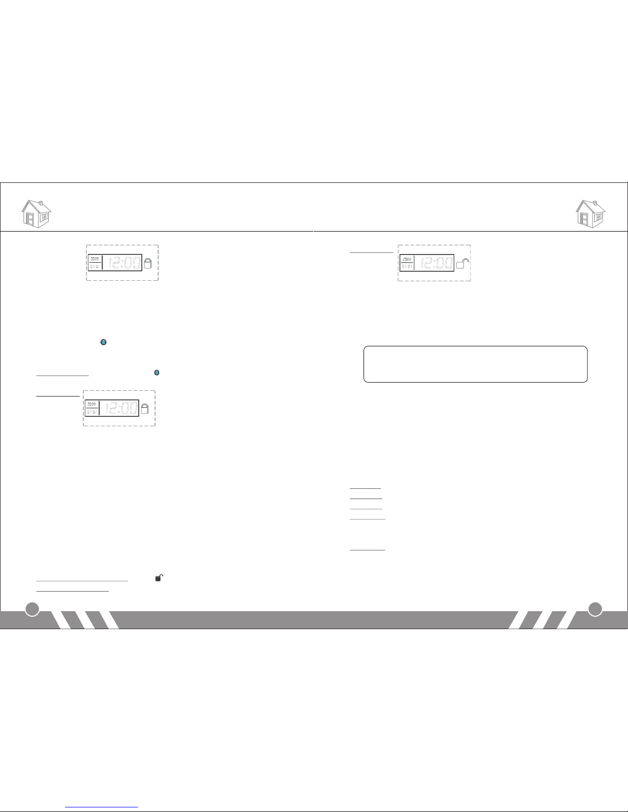
Press [Out Home ] button on keypad, system will make a beep per
second and totally 60 beeps. The [OUT ARM] indicator will be on
without flashing. It means Out Arm is set successfully.
Arm Operation: Press [Out Home ] button, the system will enter arm
status 60seconds later.
LCD display:
You can also set out arm by SMS remotely. The SMS command is:
Remote Control Password (Default: 1234) + [1]
After the setting, the host makes a "Di" sound, ARM LED is on and you
will receive a SMS: System armed.
5.Disarm
It means to stop the alarm when the main unit sounds the alarm or
make the alarm system in the state of non-warning. After disarming,
even if you trigger the detector, the main unit would not sound alarm
(excluding 24-hour defense areas).
Use keypad to input system password, then press [#] button. [Out
Home] or [At Home] lights will be off. It means disarm setting
successful.
Remote Control Operation: Press [ ] button on remote controller
Main Unit Operation: input system password + [#]
Components List
LCD display:
You can also set disarm by SMS remotely. The SMS command is:
Remote Control Password (Default: 1234) + [2]
After the setting, the host makes "Di" Di" sound, ARM LED is off and
you will receive a SMS: System disarmed.
Note:
If you send arm or disarm SMS by the mobile phone number
stored in the system before (refer to “SMS Receiving Number
Setting), you will receive two arm/disarm SMS.
6.Answer Alarm Call
When the main unit sounds alarm, it will dial the preset numbers. If no one
answers the call, the system will call the next user number automatically.
The system will call each preset numbers for 3 times in order.
If you answer the call, you will hear the pre-record voice. You can set
system via your telephone or mobile phone keypad.
If you hang-up directly without answering the call, the system will call
each preset number for 3 times circularly.
Press [*]: Read the alarm information.
Press [1]: Main unit stops alarming and Arm; it stops calling users.
Press [2]: Main unit stops alarming and Disarm; it stops calling users.
Press [3]:Siren off and monitors the scene for 30 seconds; for
continued monitoring, press [3] again to monitor for another 30
seconds.
Press [4]: Main unit starts a 30-second two-way intercom. It cannot be
controlled by the mobile during the time of intercom.
19
20
Operating Instructions
Page 13
7.Remote Control
Dial the number associated to the alarm main unit by phone (mobile
phone), and after one ringing cycle, you can hear a voice prompt
“Please enter password”. If the password is right, you will here “Press
1 to arm, Press 2 to disarm, Press 3 to Monitor, Press 4 to Intercom”. If
the password is wrong, you will hear a prompt voice “wrong password,
please re-enter”.
Press [1]: arm, if finished successfully, you will hear a voice prompt
“System armed”.
Press [2]: disarm, if finished successfully, you will hear a voice prompt
“System disarmed”.
Press [3]: monitoring for 30 seconds, to continue monitoring, press [3]
again to monitor for another 30 seconds.
Press [4]: two-way intercom for 30 seconds. You can’t operate the
main unit during this time.
8.Emergency Help
Press [Emergency ] button on keypad, or [ ] button on remote
controller or wireless panic button, the main unit will alarm and make
call to the preset user numbers.
9.System Dialing Function
In disarm status, you can use the main unit to make any call just like a
land-line telephone. Dial telephone number on keypad, press [ ]
button, the main unit will make a beep and the [Signal] indicator will be
flashing. After the call, press [ ] button again, the main unit will be in
disarm status.
10.Alarming Record Checking
In disarm state, input [*0#], then the main unit will make a long beep
and enters the state of alarm record checking. After displaying the
alarm and defense zone number indicator, the LCD screen will display
the exact alarming time of this defense zone. Press 2, you can upturn
to check the previous alarming record; press 8, downturn to check; and
press [*#] to exit checking.
Care and Maintenance
22
21
Care and Maintenance
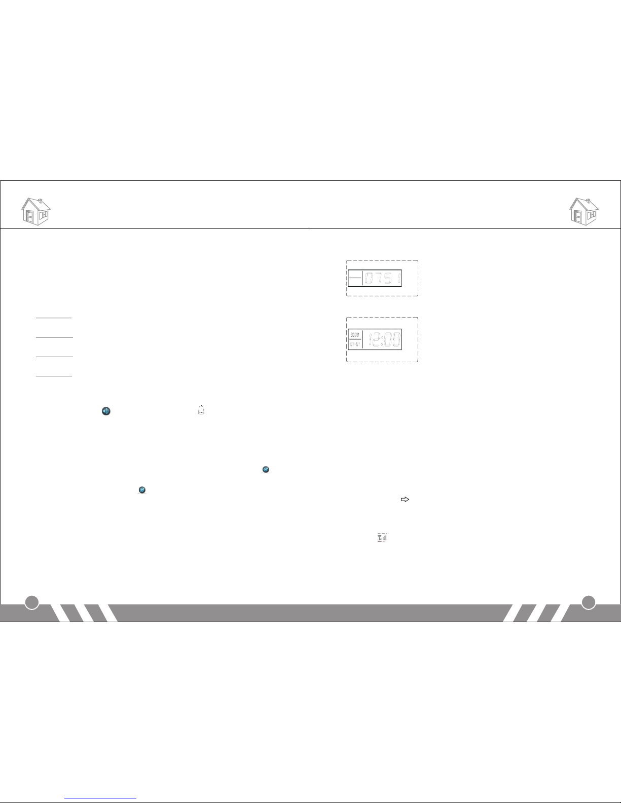
For example: the 51st defense zone; the 7th alarming; alarming time:
12:10, August 1st, 2008. LCD display for one second,
and then display the alarming time:
You can also check the alarm records by SMS (Max: Latest 9 records).
SMS Check Command: Remote Control Password (Default: 1234) + [3]
Reply SMS:
Eg: Alarm record:
NO1 Zone: 05 TIME: 11-06-25 11:37
(It indicates the first record: wireless zone 5 alarm time)
…………….
NO9 Zone: 19 Time: 11-06-25 11:45
(It indicates the first record: wireless zone 19 alarm time)
11.GSM Signal Checking
Before installing the main unit, you should check the signal of the
installing place in order to ensure the unit can perform well. In setup
state, input [81] #, the main unit will make a long beep and display
00+XX (XX indicates the intensity of the signal). And the intensity
should be within the range of 07-31; if it’s less than 07, you should
change place.
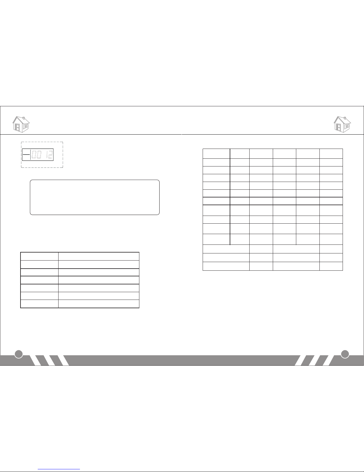
This icon indicates the signal intensity. When the intensity number is
0-7, this icon will not be shown; when it’s 8-15, this icon will be
flashing; when the number is larger than 16, this icon will be on the
screen without flash.
For example: if the signal intensity is 12, it will display as:
Page 14
[Note:]
Only under Out Arm status, the system has the function of
sending SMS alert for power failure/ power recovery. While in
Disarm or Home Arm status, it does not.
The SMS content:
Power failure: Power charger off
Power recovery: Power charger on
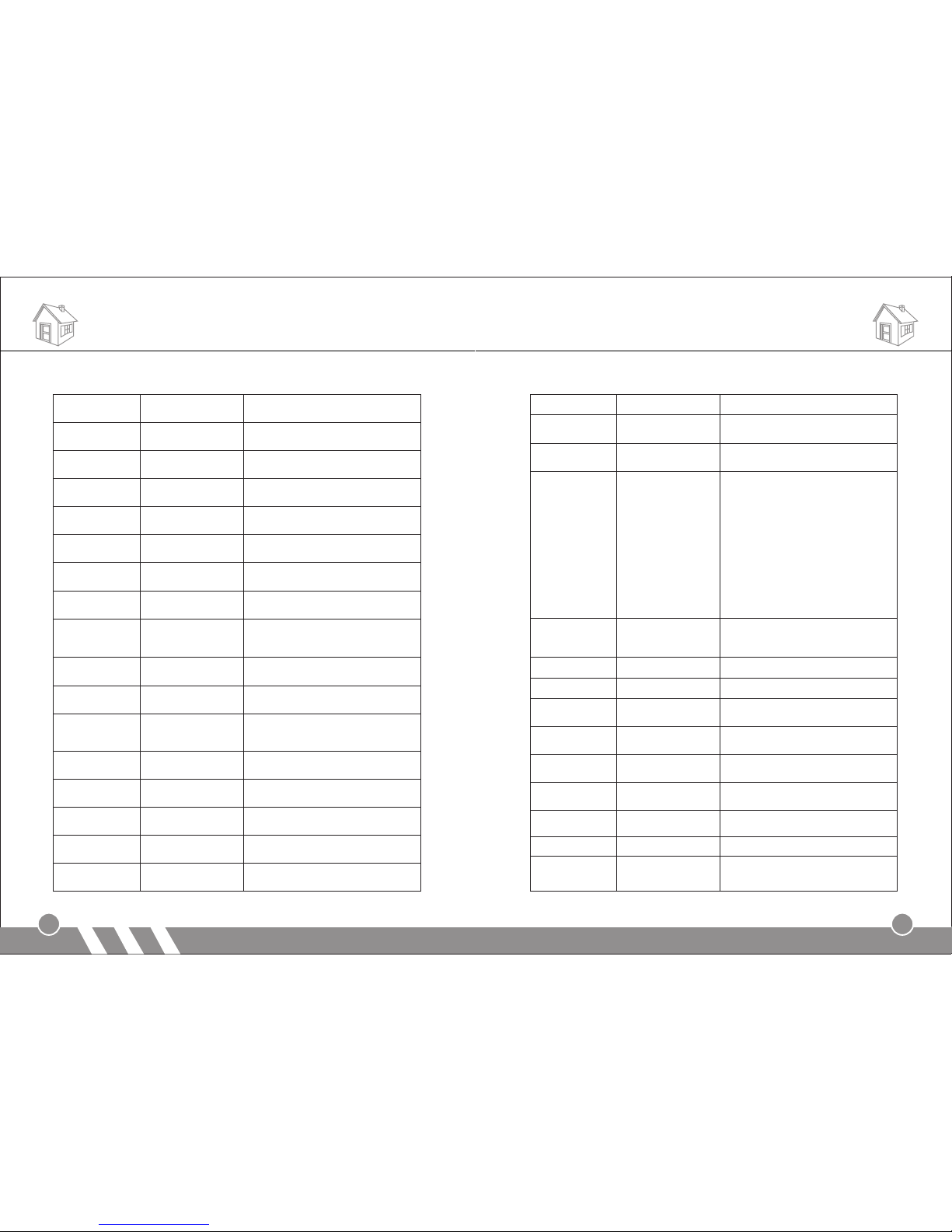
[Technical Parameters]
List 1:
Care and Maintenance
24
23
Care and Maintenance
List 2:
[Components List]
Main panel 1 pc,
Remote controller 2 pcs,
Siren 1 pc,
PIR sensor 1 pc,
Door sensor 1 pc,
Power adapter 1 pc,
User manual 1 pc.
Input Voltage DC12V/1 A
Standb y Current <55mA
Alarmin g Current <450mA
Wireless Frequency 315/433 MHz, PT2262 /EV1527, 4. 7MΩ
GSM Frequency 850/ 900/ 1800/ 1900MHz
Back -up Battery LI DC7 .4V
Siren Volume 110dB
Def ense Zo ne Arm Hom e Arm Typ e Siren
Ala rm
Inf ormat ion
Zon e 1 effec tive in vali d real -tim e Door a larm y es
Zon e 2 effec tive in vali d real -tim e Hall a larm y es
Zon e 3 effec tive eff ectiv e real- time Wi ndow al arm yes
Zon e 4 effec tive eff ectiv e real- time Ba lcony a larm ye s
Zon e 5 effec tive eff ectiv e 24 hour s Fire al arm yes
Zon e 6 effec tive eff ectiv e real- time Ga s alarm y es
eff ectiv e eff ectiv e real- time ye s
Eme rgenc y
ala rm
Eme rgenc y
but ton
Zon e 6 effec tive eff ectiv e real- time Ga s alarm y es
Zon e 7-99 ef fecti ve inva lid re al-t ime ye s
eff ecti ve inv alid r eal- time ye s
Eme rgenc y
ala rm
Wir ed defe nse
zon e(94-99)
Eme rgenc y
ala rm
Pro gram 8 888 Rem ote con trol On Pas sword
Ope ratio n Passw ord 1 234 Sir en Off
Sir en soun d time 180 se c. Home Ap plian ce Opti onal
Page 15
Care and Maintenance
26
25
Care and Maintenance
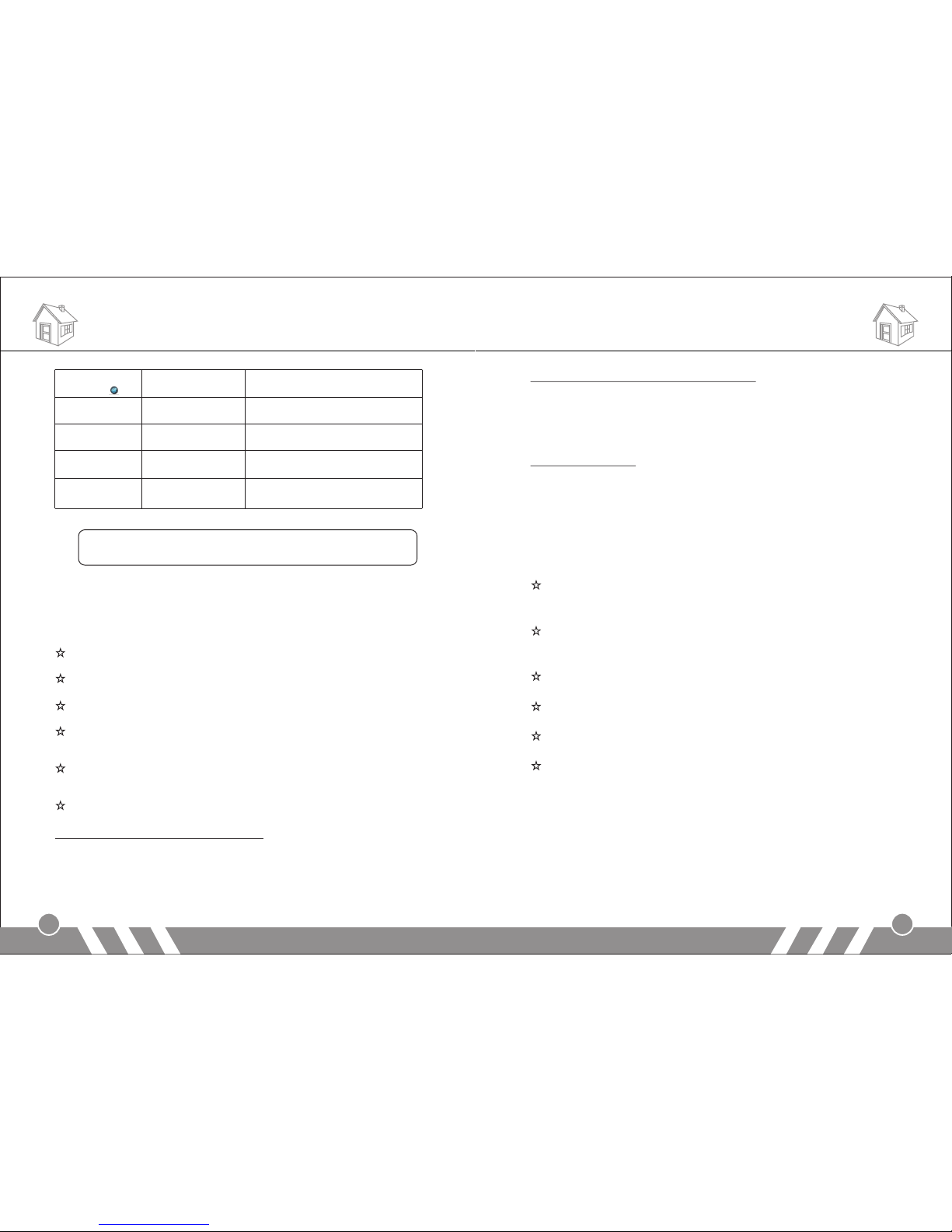
Ope ratio n
Com mands
Fun ction
Des cript ion
Rem arks
[Pr ogram
Pas sword ] + [#]
Ent er sett ings
Def ault pa sswor d: 8888
[*] + [ #]
Ent er sett ings
[20 ]+[1~ 8]
+ [#]
Cod ing of Re mote
Con troll er
Max 8 r emote c ontro llers
[23 ] +[01~ 99]
+ [#]
Cod ing of De fense
Zon es
Def ense Zo nes Num ber: 01 ~99
[24 ] +[01~ 99]
+ [#]
Del ete Def ense
Zon es
Def ense Zo nes Num ber: 01 ~99
[30 ]+[pa sswor d]
+ [#]
Cha nge Ope ratio n
Pas sword
Def ault: 1 234
[31 ]+[pa sswor d]
+ [#]
Cha nge Pro gram
Pas sword
Def ault: 8 888
[32 ] + [AA] + [B B]
+ [CC ] + [DD] +
[EE ] + [FF] + [# ]
Sys tem Time S ettin g
[AA ]: year [ BB]: mo nth[C C]: dat e
[DD ]: hour [ EE]: mi nute [F F]: sec ond
[33 ~35] + [A A] +
[BB ] + [#]
Tim ely Arm
3 gro ups of au to arm ti me
[AA ]: hour [ BB]: mi nute
[36 ~38] + [A A] +
[BB ] + [#]
Tim ely Di sar m
3 gro ups of au to disa rm time
[AA ]: hour [ BB]: mi nute
[39 ] + [0/1] + [ #]
Tim ing Co ntr ol: tu rn
on/ o ff the fu nct ion of
tim ely arm /disa rm
0: OF F 1: ON
[41 ] + [0/1] + [ #]
Wir eless
Tra nsmi ssi on Con trol
0: OF F 1: ON
[42 ] + [01~9 9]
+ [#]
Wir eless S iren
Cod ing Enc rypti on
Sir en codi ng numb er: 01~ 99
[44 ] + [01~9 9]
+ [#]
Out Ar m Delay
Tim e Sett ing
Def ault: 6 0seco nds
[45 ] + [01~9 9]
+ [#]
Ala rm Dela y
Tim e Sett ing
Def ault: n o delay
[51 ]~[56 ] + Phone
num ber + [#]
Ala rm Numb er
Set ting
6 gro ups of al armin g user nu mber
[51 ]~[56 ] + [#]
Del ete Pho ne Numb er
[57 ]~[59 ] + Phone
num ber + [#]
SMS R eceiv ing
Num ber Set ting
3 gro ups of SM S recei ving nu mber
[57 ]~[59 ] + [#]
Del ete SMS R eceiv ing
Num ber
[60 ] + [AA] + [B ] +
[C] + [ D] + [#]
Def ense Zo ne
Pro gramm ing
AA: D efens e zone nu mber: [ 01~99]
B: De fense z one typ e: [1]r eal-t ime;
[2] 4 0 secon ds dela y; [3]2 4 hours ;
[4] b ypass
C: De fense z one loc ation : [1]SO S
Ala rm; [2] F ire Ala rm; [3] Gas Lea k
Ala rm; [4] Door Al arm; [5 ]Hall A larm;
[6] Windo w Alarm ; [7]Ba lcony A larm;
[8] Bound ary Ala rm
D: Si ren ON/ OFF
[0] O FF, [1] O N
[61 ] + [01~1 2] +
[0/ 1] + [#]
Hom e Arm D efen se
Zon e Setti ng
Def ense zo ne numb er: 01~ 12;
[0] H ome arm b ut not al arm;
[1] H ome arm a nd alar m
[70 ] + [1] + [#]
Voic e Recor ding
10 se conds
[75 ] + [0/1] + [ #]
Sir en Sett ing [0] : off (de fau lt); [ 1]: o n
[76 ] + [0/1] + [ #]
Siren Setting in
“Emergency Help” mode
[0] : off (de fau lt); [ 1]: o n
[77 ] + [1/0] + [ #]
SMS N otifi catio n for
Arm / Disar m
[81 ] + [#]
GSM S ignal C hecki ng
Int ensit y: 07-3 1 (if it’ s les s than 0 7,
you s hould c hange p lace. )
[83 ] + [0/1] + [ #]
Arm / Disar m
Voic e Promp t
[0] : off; [1 ]: on ( defa ult )
[84 ] + [0/1] + [ #]
Voic e Promp t for
All Se tting s
[0] : off; [1 ]: on ( defa ult )
[88 ] + [#]
IME I Check ing
[*] + [ 0] + [#]
Ala rming R ecord
Che cking
Pre ss 2: upt urn
Pre ss 8: dow nturn
Pre ss [*#] : Exit
Page 16
Note:
the last three functions could be realized only when the GSM
signal intensity reaches 20.
[Care and Maintenance]
The alarm system has excellent design and uses advanced
technologies. It shall be used with care. The following suggestions are
required to maintain your obligations under the warranty terms, and for
prolonging the service life of the system.
Place the control panel and all parts and accessories out of
children's reach.
Keep the alarm system dry. Rain, humidity and various fluids or
moisture all will corrupt the electronic circuit.
Do not use or place the alarm system in dirty locations, otherwise
the electronic elements will be damaged.
Do no place the system in excessively hot locations. High
temperature will shorten the service life of electronic equipment,
damage batteries, deform or even melt some plastic parts.
Do not place the system in excessively cold locations. Otherwise
condensation many occur and damage the circuit board of the
alarm system.
It is recommended that you check and test the alarm system
periodically:
Check the main unit every three months:
1.Whether it can arm/disarm normally;
2.Whether it can dial the number for alarm normally;
3.Whether it can receive wireless detectors’ signal normally;
4.Whether the back-up battery can work normally.
Care and Maintenance
28
27
Care and Maintenance
Check the wireless detectors once a month:
1.Trigger wireless detectors to see if system can alarm normally;
2.Check all detectors’ batteries to see if it’s in low voltage;
3.Check whether wireless detectors can send signal to the main unit
normally.
Check the SIM card:
1.Check the use of SIM card, such as network signal, balance, etc.
2.Make sure the PIN code verification of the SIM card is closed.
3.Please keep the password and SIM card number safe, in case that
other people remote control the system illegally.
Since the alarm system is continuously in operation or standby mode,
the supply adaptor of the control panel shall be connected to a safe
and reliable socket.
Do not place the system near your bedroom or office table, because
the siren will make high-loudness sound in the case of alarm, which
may adversely affect your rest or work.
If the alarm system will not be used for a long time, please
disconnect the system from the power supply.
Please do not disassemble, repair or alter the products without
permission, or it may cause accidents and faults.
Do not drop this product on the ground or on hard objects, as it may
lead to massive impact to cause faults and damages.
Without approval and consent of relevant authorities, please do not
set “110”, “119” or the alarm phone number of police station for this
main unit.
Please read the suggestions above carefully and follow the
instructions herein. If any of the equipment does not work properly,
please send it to the dealer or authorized service point for repair.
We will try our best to solve the problem for you as soon as
possible.
[Di al tele phone
num ber] +[ ]
Sys tem Dia ling
Fun ction
[95 17530 8246]
+ [#]
Fac tory Re set
Use w ith cau tion
[op erati on
pas sword ] + [1]
Arm b y SMS
[op erati on
pas sword ] + [2]
Dis arm by SM S
Def ault op erati on pass word: 1 234
[op erati on
pas sword ] + [3]
Ala rm Reco rd
Che cking b y SMS
Def ault op erati on pass word: 1 234
Def ault op erati on pass word: 1 234
Page 17
Care and Maintenance
29
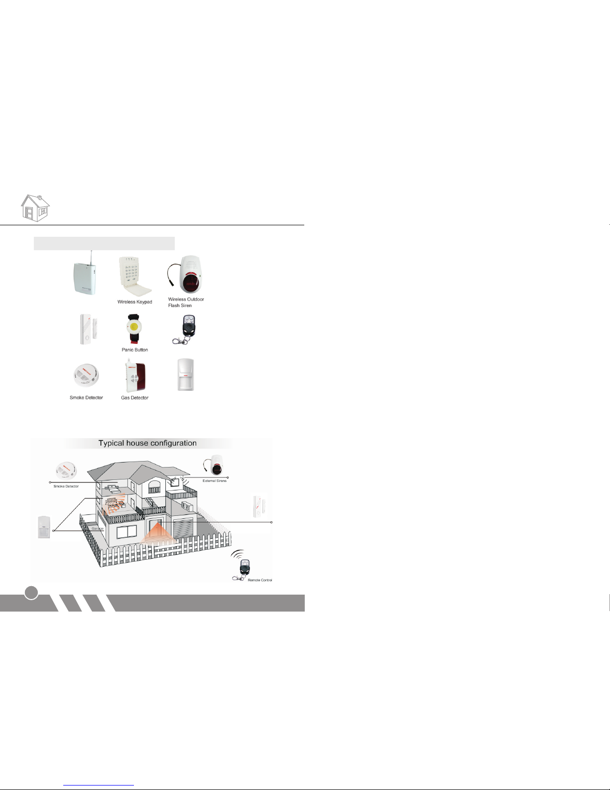
The following accessories are optional:
Optional sensors/detectors are packed separately. You can choose
according to your specific requirements.
Sig nal boo ster
Doo r senso r
PIR d etect or
Rem ote con trols
Doo r senso r
PIR d etect or
 Loading...