

Page 1
Betriebsanleitung Deutsch
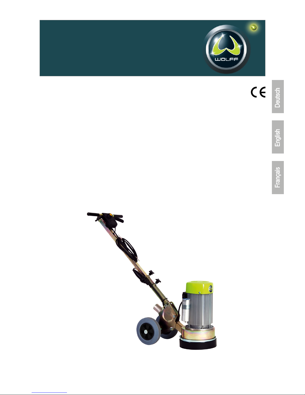
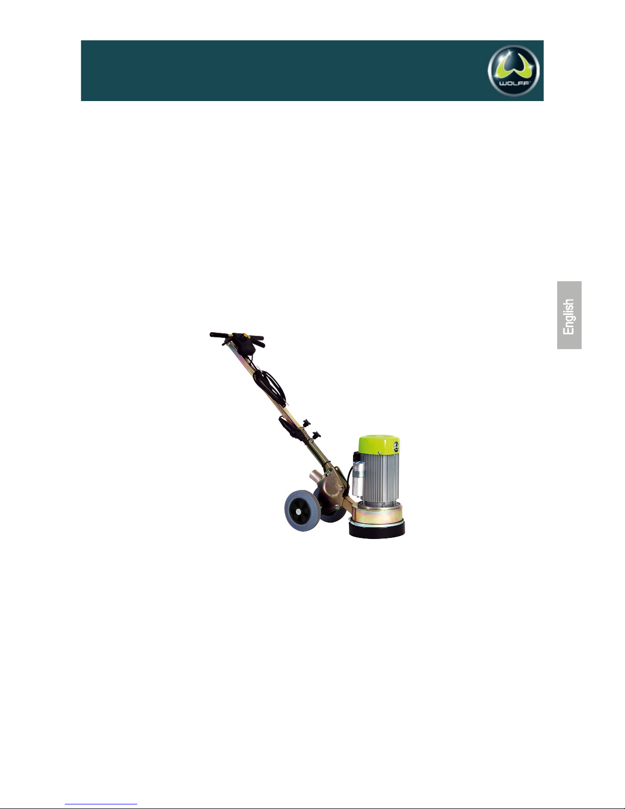
Bodenschleifmaschine ALPHA, 230 V Artikel-Nr. 037606
Operating manual English
Floor Grinder ALPHA, 230 V Item no. 037606
Mode d‘emploi Français
Ponceuse monodisque ALPHA, 230 V Réf. 037606
Art. Nr. 037768
WOLFF | Eine Marke der Uzin Utz Gruppe
WOLFF | Eine Marke der Uzin Utz Gruppe | D-71665 Vaihingen/Enz | Dieselstraße 19 | Tel. +49 (0)70 42 95 11- 0 | Fax +49 (0)70 42 95 11- 44 | E-Mail [email protected] | Internet www.uzin-utz.com
Page 2
2
07/2005
Bodenschleifmaschine ALPHA, Artikel-Nr. 021341 ab Masch. Nr. 0001/05
uSTER
Betriebsanleitung Deutsch
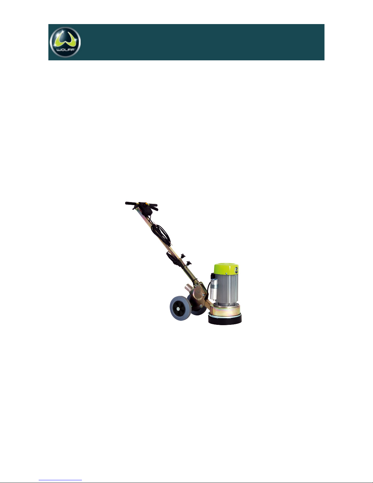
Bodenschleifmaschine ALPHA,230 V Artikel-Nr. 037606
Vor Inbetriebnahme unbedingt durchlesen und aufbewahren
Inhalt
1. Technische Daten . . . . . . . . . . . . . . . . . . . . . . . . . . . . . . . . . . . . . . . . . . . . . . . . .Seite 3
2. EG-Konformitätserklärung . . . . . . . . . . . . . . . . . . . . . . . . . . . . . . . . . . . . . . . . . . Seite 3
3. Einsatzgebiete der Werkzeuge . . . . . . . . . . . . . . . . . . . . . . . . . . . . . . . . . . . . . . .Seite 4
4. Sicherheitsregeln für den Betrieb der Bodenschleifmaschine . . . . . . . . . . . . . . . .Seite 5
5. Inbetriebnahme und Schleifen . . . . . . . . . . . . . . . . . . . . . . . . . . . . . . . . . . . . . . . .Seite 6
6. Wechsel der Werkzeuge . . . . . . . . . . . . . . . . . . . . . . . . . . . . . . . . . . . . . . . . . . . .Seite 7
7. Skizzen . . . . . . . . . . . . . . . . . . . . . . . . . . . . . . . . . . . . . . . . . . . . . . . . . . . . . . . . .Anhang
Page 3

3
07/2005
Bodenschleifmaschine ALPHA, Artikel-Nr. 021341 ab Masch. Nr. 0001/05
uSTER
Lieferumfang:
Bodenschleifmaschine ALPHA
Gehörschutz
Schutzhandschuhe
Schutzbrille
Betriebsanleitung
1.0 Technische Daten
Arbeitsbreite . . . . . . . . . . . . . . . . . . . . . . . . . . . . . . . . . .23 cm
Maschinenbreite . . . . . . . . . . . . . . . . . . . . . . . . . . . . . . . .30 cm
Maschinenlänge . . . . . . . . . . . . . . . . . . . . . . . . . . . . . . . .60 cm
Maschinenhöhe . . . . . . . . . . . . . . . . . . . . . . . . . . . . . . . .51 cm
Gewicht 230 Volt . . . . . . . . . . . . . . . . . . . . . . . . . . . . . . . 42 kg
Absaugstutzen . . . . . . . . . . . . . . . . . . . . . . . . . . . . . .Ø 50 mm
Drehzahl . . . . . . . . . . . . . . . . . . . . . . . . . . . . . . . .1.500 U/min.
Schwingungsgesamtwert ahv* . . . . . . . . . . . . . . . . . . .9,6 m/s2
Schalleistungspegel L
wa * . . . . . . . . . . . . . . . . . . . . . .100 dB(A)
Dauerschallpegel Leq* . . . . . . . . . . . . . . . . . . . . . . . . .90 dB(A)
* Messwerte: VÜA Verein zur Überwachung technischer Anlagen e.V.
2.0 EU Konformitätserklärung
Im Sinne der EG-Maschinenrichtlinie 98/37/EG (89/392/EWG),
Anhang II A. Hiermit erklären wir, dass die Bauart von
Bezeichnung: Bodenschleifmaschine
Maschinentyp: Alpha
folgenden einschlägigen Bestimmungen entspricht, die zum
unten genannten Ausgabedatum gültig waren:
EG-Richtlinie 98/37/EG (89/392/EWG),
in ihrer jeweils aktuellen Änderungsfassung
EG-Richtlinie 89/336/EWG,
in ihrer jeweils aktuellen Änderungsfassung
EG-Richtlinie 73/23/EWG (89/392/EWG),
in ihrer jeweils aktuellen Änderungsfassung
Liste der wesentlichen Normen:
EN 12100 Teil 1 „Sicherheit von Maschinen – Grundbegriffe,
allgemeine Gestaltungsleitsätze“.
Grundsätzliche Terminologie, Methodologie
EN 12100 Teil 2 „Sicherheit von Maschinen – Grundbegriffe,
allgemeine Gestaltungsleitsätze“.
Technische Leitsätze
EN 418 „Not-Aus-Einrichtung“
EN 953 „Trennende Schutzeinrichtungen“
EN 60204 Teil 1 „Elektrische Ausrüstung von Maschinen, all
gemeine Anforderungen“
EN 1050 „Leitsätze zur Risikobeurteilung“
Vaihingen/Enz 26.07.05
______________________________
(Ort und Datum der Ausstellung) (Unterschrift des Befugten)
D. Hammel – Konstruktionsleitung
Page 4
4
07/2005
Bodenschleifmaschine ALPHA, Artikel-Nr. 021341 ab Masch. Nr. 0001/05
uSTER
3.0 Einsatzgebiete der Werkzeuge
3.1 Allgemeine Einsatzgebiete
Werkzeug Diamant-
Anwendung segmente
Schleifen von ebenen Böden, A+B
Abschleifen von Zementschlämme
Einebnen von unebenen Oberflächen
- Glatte Oberfläche A
- Mittelrauhe OberflächeA B
- Rauhe Oberfläche B
Einebnen von Übergängen,
Kanten und Fugen A+B
Renovierung A
Reparatur B
Fehler beim Einbringen C
Anschleifen von
- Hartem Beton A
- Öligen Böden A
- Gestrichenen Böden A
- Epoxy Beschichtungen A
Abtragen von Oberflächen
von 1 bis 5 mm tiefe C
Entfernen von Teppich-
und Fliesenklebern B+C
Asphalt-Schleifen B
A = rot B = silber C = PKD
3.2 Einsatzgebiete der Diamantscheiben
Bearbeitung von: : Farbe:
Hochverdichtete Böden silber
Epoxyd / PU Klebereste rot
Normaler Beton / Estrich rot/silber
Aggressiver Estrich / Beton silber
Die Maschine ist nur zu benutzen
für die bestimmungsgemäße Verwendung
in sicherheitstechnisch einwandfreiem
Zustand.
Zur bestimmungsgemäßen Verwendung gehört,
das Beachten aller Hinweise aus der
Betriebsanleitung und
die Einhaltung der Inspektions- und
Wartungsarbeiten.
Page 5

07/2005
Bodenschleifmaschine ALPHA, Artikel-Nr. 021341 ab Masch. Nr. 0001/05
uSTER
Achtung !
Die B odenschleifmasc hine ALPHA ist un ter der
Berücksichtig ung gelten der Sicherheitsstandards
entwickelt worden.
Die technischen Sicherheitsvorkehrungen dürfen auf
keinen Fall entfernt oder ver ändert werden. Beim
Betrieb der Schleifmaschine sollten außerdem folgende
Punkte beachtet werden:
4.0 Sicherheitsregeln
für den Betrieb der Bodenschleifmaschine
Die Bodenschleifmaschinen dürfen nur mit sämtlichen
Schutzvorrichtungen betrieben werden.
Bei Transport, der Reinigung, der Reparatur oder der
Wartung der Maschine muss der Netzstecker gezogen
werden. Dies gilt auch für den Werkzeugwechsel.
Der Schutzring (Skizze Nr. 17) darf nur bei dem Betrieb der
Maschine direkt an der Wand abgenommen werden. Dabei
kann eine erhöhte Staubentwicklung auftreten. Eine Atemschutzmaske muss vom Maschinisten getragen werden. Beim
Betrieb auf offener Fläche muss der Ring angebracht sein.
Der Maschinist darf sich während des Betriebs nicht von
der Schleifmaschine entfernen.
Vor dem Verlassen der Schleifmaschine hat der Maschinist
den Motor stillzusetzen und das Gerät gegen ungewollte
Bewegungen zu sichern. Außerdem muss der Netzstecker
gezogen werden.
Nach Wartungs- und Instandsetzungsarbeiten müssen die
Schutzvorrichtungen wieder ordnungsgemäß angebracht
werden.
Es müssen Schallschutzmittel vom Maschinisten getragen
werden.
Es muss ein Augenschutz vom Maschinisten getragen
werden.
Es müssen Sicherheitsschuhe mit Stahlkappen vom
Maschinisten getragen werden.
Bei größerer Staubentwicklung in geschlossenen Räumen
muss die Bodenschleifmaschine mit einer Absauganlage
betrieben werden.
Je nach Bodenart und Beschichtung können beim Schleifen
Gase freigesetzt werden. Es liegt in der Verantwortung des
Anwenders ob diese Gase gefährliche Stoffe enthalten
können und ob Schutzmassnahmen ergriffen werden müssen.
Speziell beim Schleifen von z.B. asbesthaltigen Böden
müssen Maßnahmen getroffen werden, welche die Atemluft des Maschinisten rein halten. Es müssen außerdem
geeignete Filter in die Absauganlagen eingesetzt werden.
Die zu schleifende Fläche sollte besenrein sein weil loses
Material von den Schleifwerkzeugen erfasst und wegge
schleudert werden könnte. Außerdem können z.B. aus dem
Boden hervorragende Stifte , Schrauben und Bolzen besser
erkannt werden. Damit wird die Gefahr gebannt, das die
Schleifwerkzeuge mit den Teilen kollidieren und Stücke der
Werkzeuge und/oder Teile weggeschleudert werden.
5
Page 6
5.0 Inbetriebnahme und Schleifen
Netzstecker ziehen !
Nach Montage der für die Anwendung erforderlichen
Werkzeuge kann mit dem Schleifen begonnen werden.
Die Hinterradschwinge (Anhang Skizze Pos. 3) der
Schleifmaschine durch lösen der Befestigungsschrauben so
ausrichten, daß der Motor der Maschine 90° zum Boden zeigt.
Befestigungsschrauben wieder anziehen. Netzstecker einstecken. Die Schleifwerkzeuge vom Boden abheben, indem Sie die
Maschine über die Hinterräder kippen. Motor einschalten.
Nachdem der Motor hochgefahren ist, setzen Sie die
Schleifwerkzeuge vorsichtig auf dem Boden auf. Wurde die
Maschine korrekt ausgerichtet (siehe oben), ist sie beim
Schleifen leicht zu führen. Falls die Schleifmaschine nach links
oder rechts zieht, muß die Maschine mittels Ausrichtung der
Hinterradschwinge nachgestellt werden. Starke Staubentwicklung
kann durch Anschluß einer Absauganlage vermieden werden.
Bevor der Schleifvorgang beendet wird muss die Maschine ausgeschaltet werden und die Schleifwerkzeuge durch Aufsetzen
auf den Boden zum Stillstand gebracht werden. Netzstecker
ziehen.
6.0 Wechsel der Werkzeuge
Maschine über die Hinterräder kippen und umlegen.
Alle Werkzeuge bzw. Werkzeugaufnahmen werden mit
zwei Innensechskantschrauben an der flexiblen Kupplung
befestigt. Siehe Anhang „Alpha Werkzeuge“ Pos. 9.
Die Schrauben mit einem 8 mm Innensechskantschlüssel
lösen und entfernen.
Schleifwerkzeug abnehmen und auf Verschleiß überprüfen.
Neues Werkzeug gemäss Anhang „Alpha Werkzeuge“ anbringen.
Die verschiedenen Höhen der Werkzeuge müssen durch
die Stellung der Hinterradschwinge angepasst werden. Der
Motor der Schleifmaschine muß immer 90° zum Boden stehen.
7.0 Werkzeuge und Zubehör
7.1 Werkzeuge
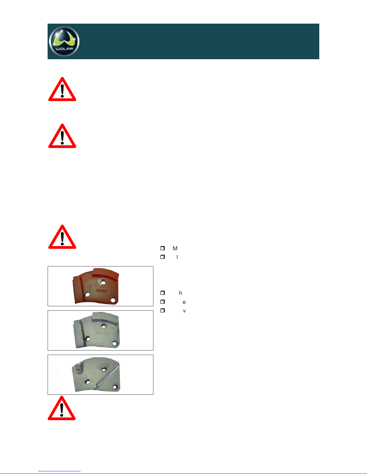
Scheibenaufnahme für Segmente . . . . . . . . . . . . .Art.nr. 51207
1 Diamant-Segment, rot . . . . . . . . . . . . . . . . . .Art.nr. 33120
zum Abtragen und Anschleifen von
(PU- und Epoxy-) Beschichtungen
(verwendbar mit 3 oder 6 Einzelsegmenten)
2 Diamant-Segment, silber . . . . . . . . . . . . . . . .Art.nr. 33846
zum Aufrauhen und Abtragen von Beton und Estrichen
und zum Anschleifen hochvergüteter
Spachtelmassen(verwendbar mit 3 oder 6 Einzelsegmenten)
3 PKD-Segment . . . . . . . . . . . . . . . . . . . . . . . .Art.nr. 34282
Verwendbar mit 3 oder 6 Einzelsegmenten
6
07/2005
Bodenschleifmaschine ALPHA, Artikel-Nr. 021341 ab Masch. Nr. 0001/05
uSTER
Achtung, beim anfahren des Motors die
Maschine festhalten, da sie mit einem Ruck hochfährt.
Achtung: Der Motor der Schleifmaschine
darf niemals eingeschaltet werden wenn die Werkzeuge
noch den Bo den berühren. Immer erst ü ber die
Hinterräder kippen und Werkzeuge damit vom Boden
abheben.
Achtung:
Vor Wartungsarbeiten Motor zum Stillstand bringen und
Netzstecker ziehen.
2
1
3
TIPP
Absauganlage TORNADO . . . . . . . . . . . . . .Art.nr. 15756
zur effektiven Absaugun g von Feinstäuben und
Grobmaterialien
Page 7
7
07/2005
07/2005
Bodenschleifmaschine ALPHA, Artikel-Nr. 021341 ab Masch. Nr. 0001/05
uSTER
Operating manual English
Floor Grinder ALPHA, 230 V Item no. 037606
Read before use
Technical Data
1. Technical data . . . . . . . . . . . . . . . . . . . . . . . . . . . . . . . . . . . . . . . . . . . . . . . . . . . . . . . . . . . . . . . . . .Page 9
2. EU-Declaration of Conformity . . . . . . . . . . . . . . . . . . . . . . . . . . . . . . . . . . . . . . . . . . . . . . . . . . . . . .Page 9
3. Tool applications . . . . . . . . . . . . . . . . . . . . . . . . . . . . . . . . . . . . . . . . . . . . . . . . . . . . . . . . . . . . . . . .Page 10
4. Safety rules for the operation of the ALPHA floor grinder . . . . . . . . . . . . . . . . . . . . . . . . . . . . . . . .Page 10
5. Operating . . . . . . . . . . . . . . . . . . . . . . . . . . . . . . . . . . . . . . . . . . . . . . . . . . . . . . . . . . . . . . . . . . . . .Page 11
6. Changing and replacing of the tools . . . . . . . . . . . . . . . . . . . . . . . . . . . . . . . . . . . . . . . . . . . . . . . .Page 12
7. Tools and Accessories . . . . . . . . . . . . . . . . . . . . . . . . . . . . . . . . . . . . . . . . . . . . . . . . . . . . . . . . . . .Page 12
Spare Parts / Drawing . . . . . . . . . . . . . . . . . . . . . . . . . . . . . . . . . . . . . . . . . . . . . . . . . . . . . . . . . . . . .Appendix
Page 8

8
07/2005
Bodenschleifmaschine ALPHA, Artikel-Nr. 021341 ab Masch. Nr. 0001/05
uSTER
1.0 Technical Data
Width of grinding . . . . . . . . . . . . . . . . . . . . . . . . . . . . . . .23 cm
Width . . . . . . . . . . . . . . . . . . . . . . . . . . . . . . . . . . . . . . . .30 cm
Length . . . . . . . . . . . . . . . . . . . . . . . . . . . . . . . . . . . . . . .60 cm
Height . . . . . . . . . . . . . . . . . . . . . . . . . . . . . . . . . . . . . . . .51 cm
Weight . . . . . . . . . . . . . . . . . . . . . . . . . . . . . . . . . . . . . . .42 kg
Hose . . . . . . . . . . . . . . . . . . . . . . . . . . . . . . . . . . . . . .Ø 50 mm
Rotation speed . . . . . . . . . . . . . . . . . . . . . . . . . . . .1.500 U/min.
Average value of acceleration ahv* . . . . . . . . . . . . . . . .9.6 m/s2
Noise level Lwa* . . . . . . . . . . . . . . . . . . . . . . . . . . . . .100 dB(A)
Noise level L
eq
* . . . . . . . . . . . . . . . . . . . . . . . . . . . . . .90 dB(A)
* Data: VÜA Verein zur Überwachung technischer Anlagen e.V.
2.0 EU-Declaration of Conformity
According to the Machine Directive 98/37/EC (89/392/EWG),
Appendix II A We hereby declare that the machine
Type: Floor Grinder
Name: Alpha
conforms with the following standards which have been valid at
the date written below:
EC-Directive 98/37/EC (89/392/EEC), in its current wording
EC-Directive 89/336/EEC, in its current wording
EC-Directive 73/23/EWG (89/392/EEC), in its current wording
List of the essential harmonised standards:
EN 12100 „Safety of machines
EN 418 „Emergency-Stop-Devices“
EN 953 „Separating safety devices“
EN 60204 Part 1 „Electric equipment of machinery,
general requirements“
EN 1050 „Guiding principles for the risk
judgement“
Vaihingen/Enz, 26.07.05
______________________________
(Authorized signature)
D. Hammel – Construction department
Comes with:
Floor Grinder ALPHA
Ear Protection
Safety gloves
Gloves
Operation manual
Page 9
9
07/2005
Bodenschleifmaschine ALPHA, Artikel-Nr. 021341 ab Masch. Nr. 0001/05
uSTER
3.0 Tool applications
3.1 General Applications
Tool Diamond
Application
Grinding of plain floors, A+B
Levelling of uneven surfaces
- Smooth surfaces A
- Semi rough surfaces B
- Rough surfaces B
Levelling of steps,
corners, joints etc. A+B
Renovation A
Repair B
Faults in concrete C
Grinding of
- Hard concrete A
- Oily and greasy floors A
- Painted floors A
- Epoxy coatings A
Removal of floor
surfaces up to 5 mm C
Removal of carpet
and tile glue B+C
Grinding of asphalt B
A = red B = silver C = PKD
3:2 Application of diamond discs
Grinding of: Description: Colour:
Hard floors silver
Normal concrete red/silver
Aggressive concrete brown
Epoxy red
4.0 Safety rules for the operation of the
ALPHA floor grinder
Intended application and operation:
Grinding of flat, horizontal, dry surfaces that are typically
concrete, asphalt or steel and with or without a coating. For
optimum performance and compatibility always use tools
supplied by CONTEC. Operation of the grinder outdoors is
only permitted if the weather is dry.
The floor grinder may only be operated by trained
professionals. The operators have read and be familiar the
contents of this manual. The floor grinder must not be operated
in areas where the hazard of explosion or fire exists.
Page 10
10
The floor grinder can only be started when the tools are not
in contact with the floor. Do always start the machine in a
tipped position. The tools and discs may be hot after use.
Take care when changing them.
The machine should always be stored in a warm, dry place
when not in use. The floor grinder may only be operated
with the dust guard (Appendix diagram No.3).
Only original tools and spare parts are to be used. The grinder
should only be operated with all safety guards in position.
When changing tools, during transportation, cleaning,
repair or maintenance the grinder must be disconnected
from the mains. The operator must never leave the machine
unattended during operation. Before leaving the machine
all rotary parts must be brought to a standstill. Electric
models must be disconnected from the power supply.
Ensure the machine cannot roll or move by itself.
After any maintenance and adjustment all safety guards must
be refitted. Ear protectors must be worn. Eye protectors
must be worn. Safety shoes with steel caps must be worn.
When operating the grinder produces large volumes of dust
the grinder should be connected to a suitable dust collector.
Depending on the floor (floor coating) grinding can produce
gases. The operator must be held responsible if the gases
generated are hazardous and whether protection is necessary.
Grinding floors containing asbestos is especially dangerous
and can cause health problems. Special masks must be
worn which keep the breathing air clean. A dust collector
must be used and should be equipped with filters suitable
for asbestos dust.
The floor must be brushed before grinding to prevent loose
material collecting in the tools and then being thrown out
with force. Anchor screws and bolts in the floor can also be
seen better if the area is clean. If the grinding head strikes
an anchor screw or bolt then serious damage can be caused
to the machine and grinding head.
5.0 Operating
After mounting the appropriate tools, the operation of the ALPHA
grinder can begin. Connect the hose of the dust collector to the
hose port of the grinder.
Adjust the grinder by turning the hand wheel of the height adjustment so that the motor axis is 90° level to the floor. Lift the tool
from the floor by tilting the machine onto it's back wheels. Switch
the motor on.
After the motor has reached full rotation place the tools carefully
on to the floor. If the machine is correctly adjusted (see above)
it is easier to move across the floor. If the machine pulls to the
left or right, the machine has to be re-adjusted with the hand
wheel of the height adjustment.
Attention !
The ALPHA floor grinders are constructed according to
existing safety rules and regulations.
These technical precautions must not be removed or
changed under any circumstances. While operating the
grinder the following points should also be kept in
mind:
Attention !
When switching on the motor the machine jumps slightly.
Never operate the floor grinder on a sloping surface.
Take care when moving the machine on a sloping
surface, substantial rolling forces can be produced.
07/2005
Bodenschleifmaschine ALPHA, Artikel-Nr. 021341 ab Masch. Nr. 0001/05
uSTER
Page 11
TIPP
Suction system TORNADO . . . . . . . . . . .Item no. 15756
to efficiently suck off fine dusts or grits,
6.0 Changing and replacing of the tools
Tilt the machine onto the back wheels and rest it on the
handlebar.
All tools are fixed with 3 screws on the tool bracket.
Loosen and remove the screws with a 6 mm Alan key.
Check the grinding tool for wear and tear for the next
application.
Fix a new tool with the 3 screws on the tool bracket.
Adjust the different heights of the tools with the hand wheel
of the height adjustment. The motor axis of the grinder has
to be 90° level to the floor.
Different tools need different heights for the rubber sealing
around the discs.
7.0 Tools and Accessories
7.1 Tools
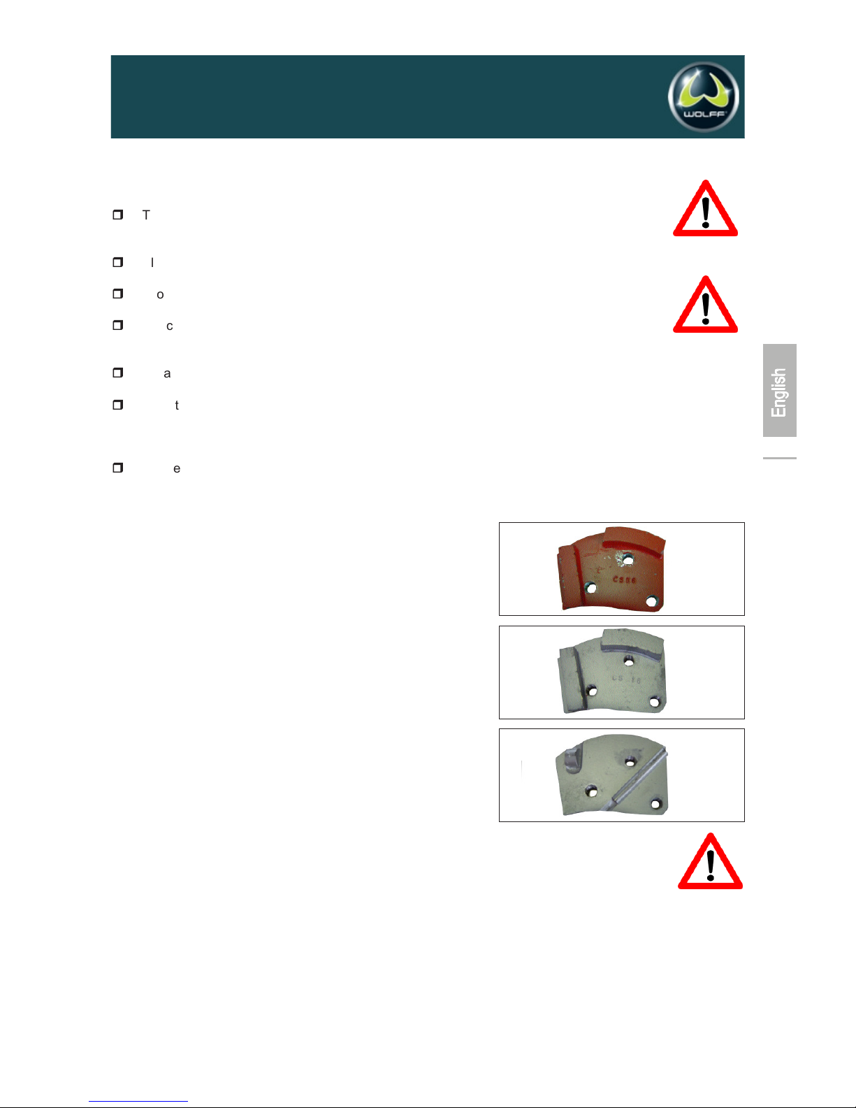
Disc holder for segments . . . . . . . . . . . . . . . . .Item no. 51207
1 Diamond segment, red . . . . . . . . . . . . . . .Item no. 33120
for removing and grinding (PU and epoxy)
coatings (can be used with 3 or 6
individual segments)
2 Diamond segment, silver . . . . . . . . . . . . . .Item no. 33846
for roughening and removing concrete
and screed and for grinding hardened fillers
(can be used with 3 or 6 individual segments)
3 PKD segment . . . . . . . . . . . . . . . . . . . . . .Item no. 34282
can be used with 3 or 6 individual segments
Attention !
Never switch the motor on while the tools still touch the
floor.
Attention !
Before working on the grinder allow the motor to come
to a complete stand still and disconnect from the mains.
2
1
3
11
07/2005
Bodenschleifmaschine ALPHA, Artikel-Nr. 021341 ab Masch. Nr. 0001/05
uSTER
Page 12
07/2005
Bodenschleifmaschine ALPHA, Artikel-Nr. 021341 ab Masch. Nr. 0001/05
uSTER
12
Mode d'emploi Français
Ponceuse monodisque ALPHA, 230 V Réf. 037606
A lire impérativement avant la mise en service et à conserver
Contenu
1. Caractéristiques techniques . . . . . . . . . . . . . . . . . . . . . . . . . . . . . . . . . . . . . . . .Page 14
2. Déclaration de conformité CE . . . . . . . . . . . . . . . . . . . . . . . . . . . . . . . . . . . . . . Page 14
3. Domaines d'application des outillages . . . . . . . . . . . . . . . . . . . . . . . . . . . . . . . . Page 15
4. Règles de sécurité pour l'utilisation de la ponceuse monodisque . . . . . . . . . . .Page 15
5. Mise en service et utilisation . . . . . . . . . . . . . . . . . . . . . . . . . . . . . . . . . . . . . . . Page 16
6. Echange des outillages . . . . . . . . . . . . . . . . . . . . . . . . . . . . . . . . . . . . . . . . . . . .Page 17
7. Outillages et accessoires . . . . . . . . . . . . . . . . . . . . . . . . . . . . . . . . . . . . . . . . . .Page 17
Liste des pièces de rechange / Vue éclatée . . . . . . . . . . . . . . . . . . . . . . . . . . . . . . .Annexe
Page 13

07/2005
Bodenschleifmaschine ALPHA, Artikel-Nr. 021341 ab Masch. Nr. 0001/05
uSTER
13
1.0 Caractéristiques techniques
Largeur utile . . . . . . . . . . . . . . . . . . . . . . . . . . . . . . . . . . .23 cm
Largeur machine . . . . . . . . . . . . . . . . . . . . . . . . . . . . . . .30 cm
Longueur machine . . . . . . . . . . . . . . . . . . . . . . . . . . . . . .60 cm
Hauteur machine . . . . . . . . . . . . . . . . . . . . . . . . . . . . . . .51 cm
Poids . . . . . . . . . . . . . . . . . . . . . . . . . . . . . . . . . . . . . . . . 42 kg
Tubulure d'aspiration . . . . . . . . . . . . . . . . . . . . . . . . . .Ø 50 mm
Vitesse . . . . . . . . . . . . . . . . . . . . . . . . . . . . . . . . . .1.500 tr/min.
Valeur totale des vibrations a
hv
* . . . . . . . . . . . . . . . . . .9,6 m/s
2
Niveau de puissance acoustique L
wa * . . . . . . . . . . .100 dB(A)
Niveau de bruit permanent Leq* . . . . . . . . . . . . . . . . .90 dB(A)
* Valeurs de mesure : Association VÜA (Association pour le contrôle technique des installations)
2.0 Déclaration de conformité CE
aux termes de la directive CE 98/37/CE (89/392/CEE), Annexe II A.
Par la présente, nous déclarons que la forme de construction du
matériel
Dénomination : Ponceuse monodisque
Type de machine : Alpha
est conforme aux dispositions pertinentes en vigueur au
moment de la date d'édition citée ci-après :
Directive CE 98/37/CE (89/392/CEE),
dans la version modifiée actuelle en vigueur
Directive CE 89/336/CEE,
dans la version modifiée actuelle en vigueur
Directive CE 73/23/CE (89/392/CEE),
dans la version modifiée actuelle en vigueur
Liste des normes essentielles :
EN 12100 Partie 1 “Sécurité des machines –
Notions fondamentales,
Principes généraux de conception“.
Terminologie de base, méthodologie
EN 12100 Partie 2 “Sécurité des machines –
Notions fondamentales,
Principes généraux de conception“.
Principes techniques
EN 418 “Equipement d'arrêt d'urgence“
EN 953 “Protecteurs“
EN 60204 Partie 1 “Equipement électrique des machines,
Règles générales“
EN 1050 “Principes pour l'appréciation du risque“
Vaihingen/Enz, 26.07.2005
______________________________
(Lieu et date de l'édition) (Signature de la personne autorisée)
D. Hammel – Direction études
Matériel fourni :
Ponceuse monodisque ALPHA
Protection de l'ouïe
Gants
Lunettes de protection
Mode d'emploi
Page 14
07/2005
Bodenschleifmaschine ALPHA, Artikel-Nr. 021341 ab Masch. Nr. 0001/05
uSTER
14
3.0 Domaines d'application des outillages
3.1 Domaines d'application généraux
Outil Segments
Application diamantés
Ponçage de sols égaux,
Ponçage de laitances A+B
Rectification de surfaces inégales
- Surface lisse A
- Surface moyennement lisse B
- Surface rugueuse B
Nivellement de passages,
bords et joints A+B
Rénovation A
Réparation B
Erreur lors de la réalisation C
Ponçage
- Béton dur A
- Sols huileux A
- Sols peints A
- Revêtements époxy A
Enlèvement de surfaces
de 1 à 5 mm de profondeur C
Enlèvement de colles moquette
et de colle carrelage B+C
Ponçage d'asphalte B
A = rouge B = argenté C = PKD
3.2 Domaines d'application des disques diamantés
Traitement de : : Couleur
Sols extrêmement compactés argenté
Résidus de résine d'époxy / PU rouge/argenté
Aggressive concrete rouge
Epoxy red
4.0 Règles de sécurité
pour l'utilisation de la ponceuse monodisque
Les ponceuses monodisques ne doivent être utilisées que
si tous les dispositifs de sécurité nécessaires sont installés.
Pour le transport, le nettoyage, la réparation et l'entretien
de la machine, il faut retirer la prise de secteur. Cela vaut
également pour l'échange des outils.
Le conducteur machine ne doit pas s'éloigner de la
ponceuse en route.
Avant de quitter la ponceuse, le conducteur machine doit
arrêter le moteur et protéger le matériel contre tout mouvement non voulu. En outre, il doit retirer la prise de secteur.
La machine ne doit être utilisée
que pour l'emploi auquel elle est destinée
que dans un état parfait à l'égard de la sécurité
technique.
Les points suivants font partie de l'utilisation conforme
à la fonction prévue :
l'observation de toutes les consignes des
instructions de service et
le respect des opérations d'inspection et d'entretien.
Attention !
La ponceuse monodisque ALPHA a été développée en
respectant les règles de sécurité standard en vigueur.
Ces règles de sécurité ne doivent en aucun cas être
jetées ou modifiées. Les points suivants doivent être
observés lors de toute utilisation de la ponceuse :
Page 15
07/2005
Bodenschleifmaschine ALPHA, Artikel-Nr. 021341 ab Masch. Nr. 0001/05
uSTER
Attention :Bien tenir la machine lors du
démarrage car elle démarre par saccade.
Attention : Ne jamais mettre en circuit le
moteur de la ponceuse lorsque les outils touchent encore
le sol. Basculer toujours d'abord les roues arrières et
lever ainsi les outils du sol.
15
Après tous travaux d'entretien ou de réparation, les dispositifs
de sécurité doivent être à nouveau correctement installés.
Le conducteur machine doit obligatoirement porter une
protection de l'ouïe.
Le conducteur machine doit obligatoirement porter une
protection de la vue.
Le conducteur machine doit obligatoirement porter des
chaussures de sécurité pourvues de coquilles en acier.
Lors de dégagement de poussière très important dans une
pièce fermée, un aspirateur doit être utilisé simultanément
à la ponceuse monodisque.
En fonction de la nature du sol et du revêtement, des gaz
peuvent se dégager pendant le ponçage. Il incombe à
l'utilisateur d'évaluer si ces gaz peuvent comprendre des
substances dangereuses ou si des mesures de protection
doivent être prises.
Surtout lors du ponçage, par exemple, de sols contenant
de l'amiante, il faut prendre des mesures particulières pour
garantir que le conducteur machine peut toujours respirer un
air propre. Les dispositifs d'aspiration doivent en plus être
pourvus des filtres appropriés.
Il faut veiller à ce que la surface à poncer soit bien nettoyée
au balai car les outils de ponçage pourraient entraîner et
lancer ces particules qui se trouvent sur le sol. Le balayage
permet aussi de détecter mieux des chevilles, des vis et
des boulons qui sont en saillie. Cela permet d'éviter le risque
d'une collision des outils de ponçage avec ces pièces et
d'un éclatement des parties d'outils et/ou des pièces.
5.0 Mise en service et utilisation
Après le montage des outils nécessaires à l'utilisation, il est
possible de commencer le travail de ponçage.
Tourner le volant pour le réglage de la hauteur (Annexe croquis
pos. 35) et aligner la ponceuse de manière à ce que le moteur
de la machine donne à 90° vers le sol. Lever les outils de ponçage
du sol en basculant les roues arrières. Mettre le moteur en marche.
Une fois que le moteur a démarré, poser les outils de ponçage
avec précaution sur le sol. Si l'alignement de la machine est
correct (voir ci-dessus), elle est facile à conduire pendant le
ponçage.
Si la ponceuse a tendance à tirer vers la gauche ou la droite, il
faut régler la machine à nouveau sur le volant pour le réglage
de la hauteur.
Une forte formation de poussière peut être évitée en raccordant
un dispositif d'aspiration.
Avant de terminer le ponçage, il faut débrancher la machine et
arrêter les outils de ponçage en les déposant avec précaution
sur le sol. Retirer la prise de secteur.
Page 16
6.0 Echange des outillages
Basculer la machine sur les roues arrières et la déposer ainsi.
Tous les outils et/ou porte-outils sont fixés sur la plaque de
fixation à l'aide de trois vis à six pans creux.
Desserrer les vis avec une clé mâle coudée pour vis à six
pans creux 6 mm et les enlever.
Retirer l'outil de ponçage et vérifier l'usage éventuel de
l'outil pour sa future utilisation.
Monter le nouvel outil selon la description dans l'annexe
“Outils Alpha“.
Les différentes hauteurs des outils doivent être réglées
avec le volant pour le réglage de la hauteur. Le moteur de
la ponceuse doit toujours être placé à 90° par rapport au sol.
Les différentes hauteurs d'outil demandent des joints en
caoutchouc pour la cloche de ponçage en différentes largeurs.
7.0 Outillages et accessoires
7.1 Outillages
Porte-disque pour segments . . . . . . . . . . . . . . . . . . .Réf. 51207
1 Segment diamanté, rouge . . . . . . . . . . . . . . . .Réf. 33120
pour enlever et poncer des
revêtements (PU et époxy)
(utilisable avec 3 ou 6 segments individuels)
2 Segment diamanté, argenté . . . . . . . . . . . . . . .Réf. 33846
pour abraser et enlever du béton
et de la chape et pour poncer
des ragréages traités
(utilisable avec 3 ou 6 segments individuels)
3 Segment PKD . . . . . . . . . . . . . . . . . . . . . . . . . .Réf. 34282
utilisable avec 3 ou 6 segments individuels
Attention :
Avant d'initier les travaux d'entretien, arrêter le moteur
et retirer la prise de secteur.
ASTUCE
Dispositif d'aspiration TORNADO . . . . . . . . . .Réf. 15756
pour l'aspiration efficace des poudres fines et des
matériaux grossiers
2
1
3
WOLFF | Eine Marke der Uzin Utz Gruppe | D-71665 Vaihingen/Enz | Dieselstraße 19 | Tel. +49 (0)70 42 95 11- 0 | Fax +49 (0)70 42 95 11- 44 | E-Mail [email protected] | Internet www.uzin-utz.com
WOLFF | Eine Marke der Uzin Utz Gruppe
 Loading...