

Page 1
TM
INSTALLATION
MANUAL
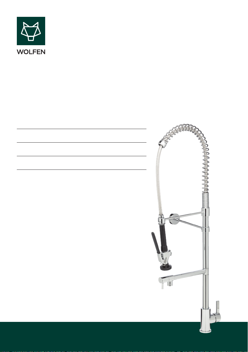
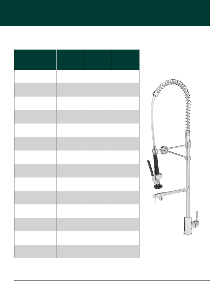
252430 Wolfen Pre Rinse Sink Mixer
252452 Wolfen Compact Pre Rinse Sink Mixer
252431 Wolfen Pre Rinse Trigger Spray
Installation Details | Warranty
Page 2

TM
CONTENTS
Intro 03
Technical Information 04
Unit Components 06
Installation Instructions 08
Warranty 10
Page 3

Delivering unrivalled quality
Designed for absolute performance, Wolfen’s commercial mixer products set new
standards in quality and durability. Ergonomic design combined with precision
engineering ensures that every Wolfen product is easy-to-use and made to last.
Here are just some of the many innovative features that make Wolfen mixers the
smart solution.
TM
Infection control
• Food grade hose
• Minimum crevices for bacteria
build up
Commercial durability features
• Stainless steel spray jet head
• Stainless steel braided hose
with external lining
• Wall fixing bracket for
ongoing stability
Installation and servicing
• Cut-down wall bracket with height
and projection adjustment
The more
stars the more
water efficient
WATER RATING
www.waterrating.gov.au
litres per
4.5
minute
(spray tap)
In accordance with A S/NZS 6400
Licence No. 1334
GENTEC AUSTRALIA
Second outlet
5 star
6 litres per minute
Suitable for High Pressure applications
(minimum 150kPa)
WaterMark
AS/NZS 3718
WMKA25617
TM
Usage features
• Easy operation with front
control pot filler
• Tensioned polished spring
for maneuverability
• Trigger spray clip enables
effortless continual use
Anti vandal features
• Allen key fixing
Application
• Commercial food premises
3
Page 4
WOLFEN INSTALLATION MANUAL | Technical Information
TECHNICAL INFORMATION
Model
Product Code
Product Type
Colour
Finish
Material
Cartridge Type
Min Continuous Flow
Working Pressure
Max Continuous Flow
Working Pressure
Min Continuous
Working Temperature
Max Continuous
Working Temperature
Pre Rinse
Sink Mixer
252430 252452 252431
Pre Rinse unit Pre Rinse unit Hand spray
Chrome Chrome Chrome
Polished Polished Polished
Brass Brass Brass
Ceramic Disc
Cartridge
150kPa 150kPa 150kPa
450kPa 450kPa 450kPa
5°C 5°C 5°C
80°C 80°C 80°C
Pre Rinse
Sink Mixer
Compact
Ceramic Disc
Cartridge
Trigger
Spray
N/R
Max Static Pressure
Height
Clearance (Pot Filler)
Reach (Trigger Spray)
450kPa 450kPa 450kPa
1059mm 800mm N/R
250mm 150mm N/R
250mm 250mm N/R
* Regular service must be carried out on the product to avoid product faliure.
4
WOLFEN INSTALLATION MANUAL | Wolfen Pre Rinse Sink Mixer
Page 5
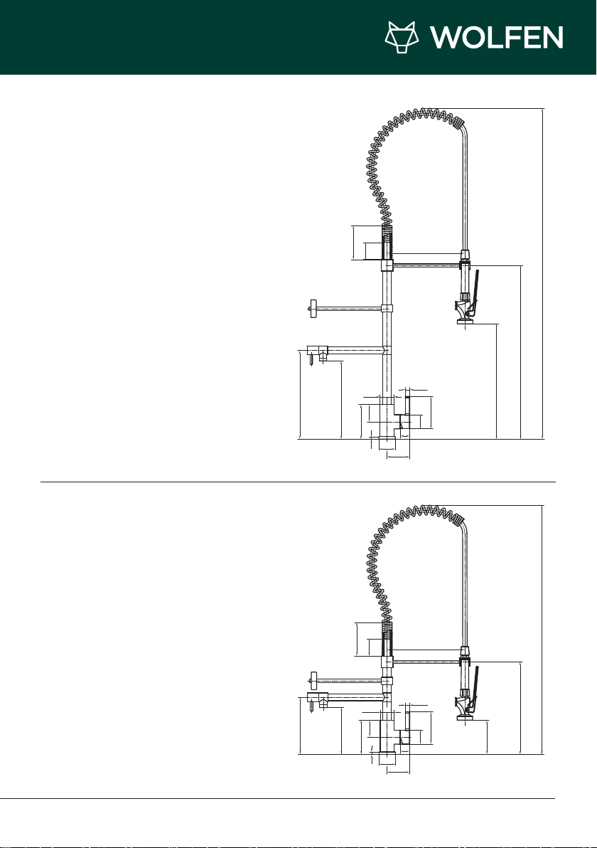
Wolfen Pre Rinse Sink Mixer
252430
TM
Wolfen Compact Pre Rinse Sink Mixer
252452
284
108
250.52
108
54.5
Ø45
110.5
55
8
54.5
Ø53
72.3
250
1059
556
14.5
103.3
Ø45
30
369
620
250
184
150.52
110.5
Ø45
14.5
55
Ø53
8
72.3
103.3
Ø45
30
297
110
5
Page 6

WOLFEN INSTALLATION MANUAL | Unit Components
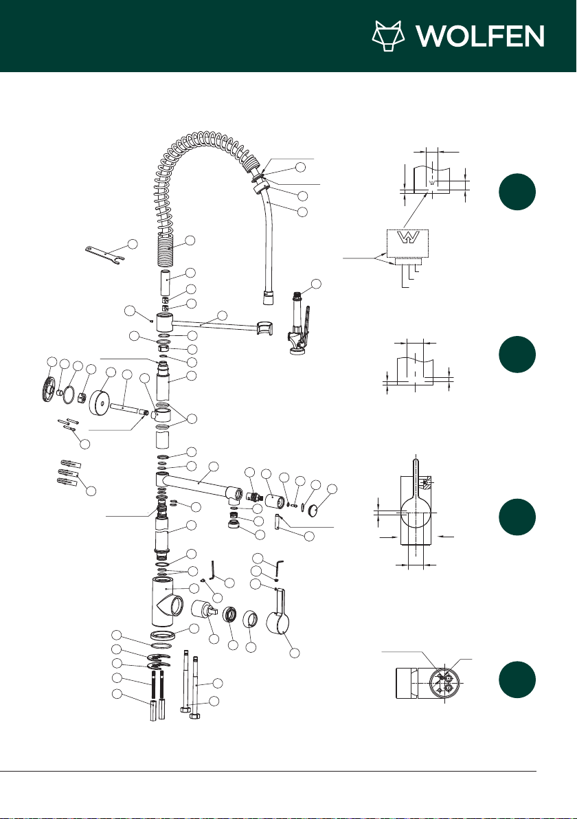
UNIT COMPONENTS
No. Code Description Qty
01 84060659 Handle 1
02 93053 S2. 5 Allen Key 1
03 94433 Handle Plug 1
04 92042 M5 x 5 Grub Screw 2
05 WA824-10 M37 x 1.25 Cap 1
06 WA824-9 M37 x 1.25 Lock Nut 1
07 K-35A Cartridge 1
08 Body 1
09 MX613-1 Ø53mm Base Ring 1
10 82000015 M4 x 8 Grub Screw 1
11 22700-9 S3 Allen Key 1
12 3200-7 Ø22 x 2.5 O Ring 2
13 DJ097-3 Washer 1
14 83060277 Raser 1 1
15 94142 Bs015 O Ring 3
16 84060043 Aerator Housing 1
17 90253 Aerator 1
18 76F-3 Ø15.2 x 2.2 O Ring 1
19 84060093 Handle, Lever 1
20 TSF26-9 Handle, Cap 1
21 SHA06-2 Ø15 x 1.5 O Ring 1
22 82000017 M4 x 10 Screw 1
23 TSF26-7 Ø12 x Ø4.3 x 1.2 Washer 1
24 TSF26-6 Handle, Body 1
25 84000132 C/Disc Cartridge 1
26 83060280
27 81000095 Ø20 x 2 O Ring 4
28 81000012 Thrust Washer 2
29 81000002 Bs121 O Ring 3
Swivel Outlet, Brazed
Assembly, Pot Filler
1
No. Code Description Qty
30 83060278 Riser 2 1
31 71438-8 Washer 1
32 94167 Bs019 O Ring 1
33 83060279 Support Arm 1
34 93064 Check Value 8.0L/Min 1
35 93024 Check Value 1
36 71438-9 Extension Tube 1
37 84060063
38 84050533 Spanner For Hose 1
39 81000011 Washer For Spring 1
40 84060086 Cover Plate For Spring 1
41 82000012 Flexible Hose Assembly 1
42 82000026 Trigger Spray Gun, Black 1
43 84060095 Bracket 1
44 84060094 Bracket Arm 1
45 84060078 Bracket Cover 1
46 84000081 Lock Nut, Bracket 1
47 94103 Bs130 O Ring 1
48 84000080 Lock Sleeve, Bracket 1
49 84000079 Fixing Plate, Bracket 1
50 82000005 M4 x 32 Screw 3
51 81000050 Wall Plug 3
52 94154 Bs132 O Ring 1
53 WA872-4 Fixing Washer 1
54 WA872-3 Fixing Plate 1
55 WA872-1B M6 x 65mm Fixing Bolt 2
56 WAS872-2 M6 x 42 Fixing Nut 2
57 82000008 Flexible Hose-Hot 1
58 82000007 Flexible Hose-Cold 1
Spring, Coiled Hose
Support
1
6 WOLFEN INSTALLATION MANUAL | Wolfen Pre Rinse Sink Mixer
Page 7
TM
LOCTITE 495
LOCTITE 495
39
37
38
36
35
34
33
32
29
4
31
15
30
29
43
44
45
46
47
48
49
50
51
28
27
26
25
24
23
22
21
20
19
18
17
16
2
3
4
11
12
13
14
15
10
8
9
52
53
54
55
56
7
6
5
58
57
1
C
H
LOCTITE 290
LOCTITE 680
LOCTITE 680
LOCOTITE 680
40
41
42
LASER
MARKING
STANDARD NUMBER
16
14
B (BACK)
5
AS/NZS 3718
WMKA25617
121215
BATCH NUMBER
DATE
MONTH
YEAR
A (FRONT)
B
Ø3
RED MARK
HOT IN
HC
A
6
22
25
5
6
AS/NZS 3718
WMKA25617
121215
STANDARD NUMBER
16
14
B (BACK)
5
AS/NZS 3718
WMKA25617
121215
BATCH NUMBER
DATE
MONTH
YEAR
AS/NZS 3718
WMKA25617
121215
STANDARD NUMBER
16
14
B (BACK)
5
AS/NZS 3718
WMKA25617
121215
BATCH NUMBER
DATE
MONTH
YEAR
A (FRONT)
25
6
AS/NZS 3718
WMKA25617
121215
STANDARD NUMBER
16
14
B (BACK)
5
AS/NZS 3718
WMKA25617
121215
BATCH NUMBER
DATE
MONTH
YEAR
A (FRONT)
B
HC
A
6
22
25
5
6
AS/NZS 3718
WMKA25617
121215
16
AS/NZS 3718
WMKA25617
5
14
121215
Fig. 1
B (BACK)
LASER
MARKING
AS/NZS 3718
WMKA25617
121215
MONTH
YEAR
STANDARD NUMBER
BATCH NUMBER
DATE
25
Fig. 2
5
6
A
RED MARK
HOT IN
22
6
A (FRONT)
HC
Fig. 3
B
Ø3
Fig. 4
7
Page 8

WOLFEN INSTALLATION MANUAL | Installation Instructions
INSTALLATION INSTRUCTIONS
Important Note
Mixer must be installed to the requirements of AS/NZS 3500 by
a qualified plumber. Your mixer comes to you already factory
assembled and tested. We do not recommend the dismantling
of any internal part of the mixer. The mixers are factory tested
and sealed so as to give the best performance.
1. Place the base o-ring (9) on the underside of
the mixer body (8).
2. Screw in the hot and cold flexible connectors
(57 & 58) to the mixer body (8).
3. Screw in the fixing bolt (55) into the mixer body
(8) and tighten with a screw driver.
4. Place the mixer unit over the pre-punched
tap hole in the sink. Feed the flexible
connectors through first.
5. From underneath the sink or basin, slide on
the U-shaped fixing washer (53), then the
U-shaped fixing plate (54).
6. Screw on the long hex nut (56) until the mixer
base is firmly fixed to the sink. Tighten with a
socket set or tube spanner.
7. Connect the hot and cold flexible connectors
to the inlet isolation valves. The unit must be
installed with the main mixer handle to the
side.
8. Fit the main riser assembly into the mixer body
by pushing the twin o-ring spigot downward,
then fit and tighten the allen key screw (10) with
the allen key provided (11).
Note: the wall support bar (44) can be slid up or
down to the desired height to enable fixing to the
wall or splashback.
9. Ensuring the riser is 90 degrees to the wall,
measure and cut the wall support bar to a
length with a 2 to 5mm gap from the wall.
Installation Instructions
1. Please flush out new pipe work prior to connecting the
new mixer.
2. All mixers should be installed with isolating stop cocks
(Arco brand recommended).
3. This tap is suitable for high pressure applications where both
hot and cold water supply pressures are at 150kPa or above.
10. Slide on the chrome cover flange (45), nut (46),
brass olive (48) & wall fixing plate (49) onto the
wall support bar (44) as shown in exploded
parts diagram.
11. Fit the o-ring (47) to the groove on the fixing
wall plate.
12. Swing the wall support bar into position and
mark the three holes for drilling into the wall.
13. Swing the wall support bar to the left or right to
enable the three holes to be drilled.
14. For a masonry wall use the wall anchors
provided (51) with screws (50).
15. For a timber backed wall use the screws
provided (50).
Note: For a stainless steel splashback and/or cool
room panel wall, ensure the fixing method used
results in a solid fixing.
16. Swing the wall support bracket back into
position, line up the holes and screw the fixing
plate back to the wall. Tighten the brass nut and
olive, ensuring a firm and solid installation. Slide
the chrome cover plate over the wall plate.
Note: The brass MI thread on the end of the end of
the trigger spray hose swivels, so you do not have
to spin the whole hose around when connecting the
hose to the riser assembly.
17. Fit the flat washer (31) into the top of the riser
assembly to ensure a water tight seal.
* To ensure longevity of the product we recommend Pressure reduction valves (PRV's)
not pressure limiting valves (PLV's) set at 350kPa working pressure (hot/cold).
8 WOLFEN INSTALLATION MANUAL | Wolfen Pre Rinse Sink Mixer
Page 9
TM
18. Slide the spring return back to expose the MI
brass connecting thread.
19. Using the open ended spanner provided, screw
the brass MI end of the flexible hose into the
top of the riser assembly. Do up firmly but do
not over tighten. Support the weight of the
hose and spring while tightening to prevent
cross threading and kinking of the hose.
20. Slide the spring back over the end of the hose
until it sits on top of the riser assembly.
21. Fit the washer (39) to the other end of the
flexible hose.
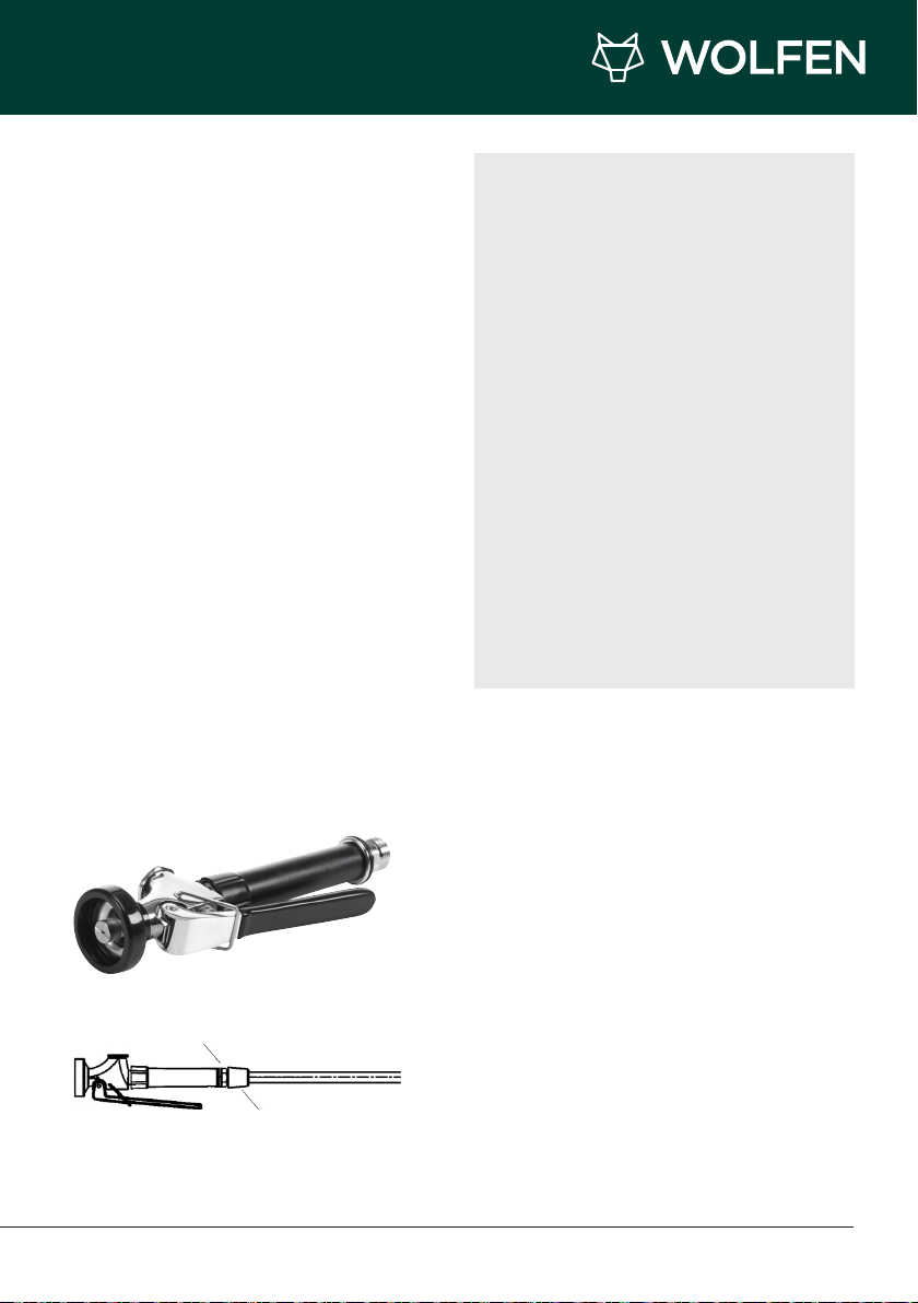
22. Screw the trigger spray unit to the flexible
hose. Tighten firmly using a spanner on the flat
section of the loose nut.
23. Turn on the water and test the unit.
Operating Instructions
When not in use, the mixer should be turned off at
the mixer cartridge so the unit is not under mains
pressure when unsupervised.
The sticker supplied must be installed in a
prominent position
The hose must not be overextended, obstructed or
bent forcibly.
Tighten using flats on trigger spray
Tighten using flats on the hose connector
IMPORTANT INFORMATION
• The mixer can only be used on main
pressure systems.
• The warranty is extended to the purchaser
only and is not transferable.
• Misuse of the product is not covered by
warranty.
• Use only suitable agents to clean the surface
of your mixer(i.e. no abrasive cleaners.
• If the incoming water pressure exceeds
450kPa, it is recommended that you install
an approved pressure reduction valve (PRV).
• Approved operating temperature is not
to exceed 80°C. Optimum operating
temperature is 60°C.
• Minimum operating pressure is 150kPa.
• Maximum pressure is 450kPa, optimum
working pressure is 350kPa.
There are two fixing methods to connect the
trigger spray to the hose:
1. Using Teflon Tape
• Insert the white washer into the hose adaptor.
• Apply adequate Teflon tape to the male thread
of the trigger spray.
• Screw hose connection on to trigger spray then
tighten firmly against O ring Supplied on trigger)
2 Using Loxeal
• Insert the white teflon washer into the hose
adaptor.
• Apply Loxeal to the male thread of the trigger
spray.
• Screw hose connection on to trigger spray then
tighten firmly against oring. Test to ensure there
are no leaks.
* Regular service must be carried out on the product to avoid product faliure.
9
Page 10

WOLFEN INSTALLATION MANUAL | Warranty
REECE PRODUCT
QUALITY GUARANTEE
You have purchased a quality product from Reece
Australia Pty Ltd ABN 84 004 097 090 (“Reece”).
This product is covered by a 5 year replacement
product warranty and a 12 month warranty over
spare parts and labour.
5 YEAR WARRANTY
This warranty covers faults in the product
construction, material and assembly. Products
which are within 5 years from the date of purchase,
found upon inspection by an authorised Reece
representative, to be defective in construction,
material or assembly, will be repaired or exchanged
with an equivalent product free of charge.
Replaced items become Reece’s property.
All replacement products will be available for
collection without charge to the customer at the
nearest Reece branch to the customer’s location,
or elsewhere as agreed between the customer
and Reece.
Labour and Spare Parts
The labour for the replacement of products
and spare parts to which this warranty applies
will be supplied by Reece or relevant supplier
using licensed plumbers engaged by Reece or
relevant supplier within 1 year from the date of
purchase. Spare parts other than those listed in
the Manufacturer’s Provisions above, which are
within 1 year from the date of purchase found upon
inspection by an authorised Reece representative
to be defective in construction, material or
assembly, will be replaced free of charge.
Warranty Conditions
This warranty will apply only under all of the
following conditions:
• The item has been installed by a
licensed plumber
• Failure is due to a fault in the manufacture
of the product
• Proof of purchase (including the date
of purchase) is provided
• The installation of the product is in
accordance with the instructions provided
This warranty does not cover products purchased
as an ex-display without being fully checked and
tested for sale by the manufacturer.
This warranty does not include faults caused by:
• Unsuitable or improper use
• Incorrect installation or installation not in
accordance with the instructions provided
• Installation or part installation by the
purchaser or any person other than a
LICENSED PLUMBER
• Normal wear and tear
• Inadequate or complete lack of
maintenance
• Chemical, electrochemical or
electrical influences
• Harsh detergents or abrasive cleaners
used on product finishes
EXCLUSIONS
To the fullest extent permitted by law, Reece
excludes all liability for damage or injury to any
person, damage to any property, and any indirect
consequential or other loss or damage.
CLAIM PROCEDURE
For all warranty queries customers are to contact the
branch where the product was purchased. These
details can be found on your purchase invoice.
Our goods come with guarantees that cannot be
excluded under the Australian Consumer Law.
You are entitled to a replacement or refund for a
major failure and for compensation for any other
reasonably foreseeable loss or damage. You are
also entitled to have the goods repaired or replaced
if the goods fail to be of acceptable quality and the
failure does not amount to a major failure.
Don’t risk it, use a licensed plumber.™
5
Q
YEAR
U
A
E
E
T
L
N
I
T
A
Y
R
G
A
U
10 WOLFEN INSTALLATION MANUAL | Wolfen Pre Rinse Sink Mixer
Page 11

IF AFTER CHECKING THE
INSTALLATION INSTRUCTIONS
AND IMPORTANT
INFORMATION, THE PROBLEM
HAS NOT BEEN IDENTIFIED,
PLEASE CONTACT GENTEC
CUSTOMER SUPPORT ON:
+61 2 9211 4422 or
[email protected]
TM
Page 12

reece.com.au/wolfen
TM
 Loading...