

Page 1
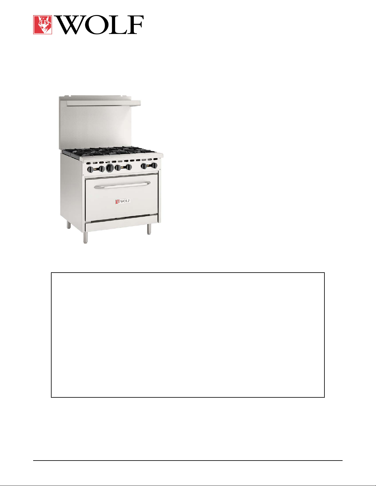
SERVICE MANUAL
WX RANGE
WX24
WX36
WX60
WX60F
- NOTICE -
This Manual is prepared for the use of trained Hobart Service Technicians and should not
be used by those not properly qualified.
This manual is not intended to be all encompassing. If you have not attended a Hobart Service
School for this product, you should read, in its entirety, the repair procedure you wish to
perform to determine if you have the necessary tools, instruments and skills required to
perform the procedure. Procedures for which you do not have the necessary tools,
instruments and skills should be performed by a trained Hobart Service Technician.
The reproduction, transfer, sale or other use of this manual, without the express written
consent of Hobart, is prohibited.
This manual has been provided to you by ITW Food Equipment Group LLC ("ITW FEG")
without charge and remains the property of ITW FEG, and by accepting this manual you agree
that you will return it to ITW FEG promptly upon its request for such return at any time in the
future.
WOLF IS A DIVISION OF ITW FOOD EQUIPMENT GROUP, LLC 3600 NORTH POINT BLVD., BALTIMORE, MD 21222
F45992 (1123)
Page 2

WX RANGE
TABLE OF CONTENTS
1. GENERAL ............................................................................................... 3
INTRODUCTION ....................................................................................... 3
SPECIFICATIONS ...................................................................................... 3
INSTALLATION, OPERATION AND CLEANING ......................................................... 3
TOOLS ................................................................................................. 3
LUBRICATION ......................................................................................... 3
2. REMOVAL AND REPLACEMENT PARTS ................................................................ 4
MANIFOLD COVER .................................................................................... 4
KICK PANEL ........................................................................................... 4
STANDARD OVEN PILOT ASSEMBLY AND THERMOCOUPLE ......................................... 4
STANDARD OVEN BURNER & ORIFICE HOOD ........................................................ 6
OVEN THERMOSTAT .................................................................................. 7
TOP BURNER PILOT VALVE ........................................................................... 8
TOP BURNER CONTROL VALVE ...................................................................... 8
TOP BURNER ASSEMBLY ............................................................................. 9
OVEN DOOR ......................................................................................... 10
DOOR STOP .......................................................................................... 13
GAS PRESSURE REGULATOR ....................................................................... 13
GRIDDLE PILOT ASSEMBLY AND THERMOCOUPLE ................................................. 14
GRIDDLE BURNER ORIFICE HOOD .................................................................. 15
3. SERVICE PROCEDURES, TEST AND ADJUSTMENTS ................................................. 16
TOP BURNER PILOT ADJUSTMENT .................................................................. 16
BURNER AIR SHUTTER ADJUSTMENT ............................................................... 16
BURNER NOZZLE CHECK ............................................................................ 16
OVEN THERMOSTAT BY-PASS FLAME ADJUSTMENT
OVEN THERMOSTAT TEMPERATURE CALIBRATION ................................................ 17
THERMOCOUPLE TEST .............................................................................. 18
OPERATION ...................................................................................... 18
PILOT CHECKS ................................................................................... 18
THERMOCOUPLE CHECKS ...................................................................... 18
4. FIRMWARE / SOFTWARE .............................................................................. 20
FIRMWARE / SOFTWARE ............................................................................ 20
5. PROGRAMMING ....................................................................................... 21
PROGRAMMING ...................................................................................... 21
6. ELECTRICAL OPERATION ............................................................................. 22
COMPONENT LAYOUT AND FUNCTION .............................................................. 23
7. SEQUENCE OF OPERATION ........................................................................... 25
SEQUENCE OF OPERATION ......................................................................... 25
8. DIAGRAMS ............................................................................................. 26
DIAGRAMS ........................................................................................... 26
............................................... 16
9. TROUBLESHOOTING .................................................................................. 27
TROUBLESHOOTING ................................................................................. 27
F45992 (1123)
Page 2 of 27
Page 3
WX RANGE - 1. GENERAL
1. GENERAL
INTRODUCTION
This manual is applicable only to models listed on the
cover page.
models unless specified. Pictures and illustrations can
be of any model unless they need to be model specific.
Model Burners Total Input BTU / HR
WX24-4BN 4 143,000
WX24-4BP 4 143,000
WX36-6BN 6 198,000
WX-36-BP 6 198,000
WX60F-6B2
4GN
WX60F-6B2
4GB
WX60-10BN 10 340,000
WX60-10BP 10 340,000
Gas Pressures
• Manifold/Operating Pressure
Procedures in this manual will apply to all
SPECIFICATIONS
6 268,000
6 268,000
Natural: 5 in. W.C.
VOM with measuring micro amp current tester.
•
Any VOM with minimum of CAT III 600V, CE
certified. Sensitivity of at least 20,000 ohms per
volt can be used. In addition, meter leads must
also be a minimum of CAT III 600V.
• Clamp on type amp meter with minimum of
NFPA-70E CAT III 600V, UL/CSA/TUV listed.
• Temperature tester (K type thermocouple
preferred).
• Manometer.
Special
• Loctite® 246™ for use on door handle mounting
screws.
• 3/4" pipe tee and hose barb assembly for
temporarily checking manifold pressure when a
pressure tap is not available in the gas manifold
on some models.
• Pipe taps may be needed to clean or repair
internal threads on gas manifolds. Use a wire
brush to clean external pipe threads on fittings.
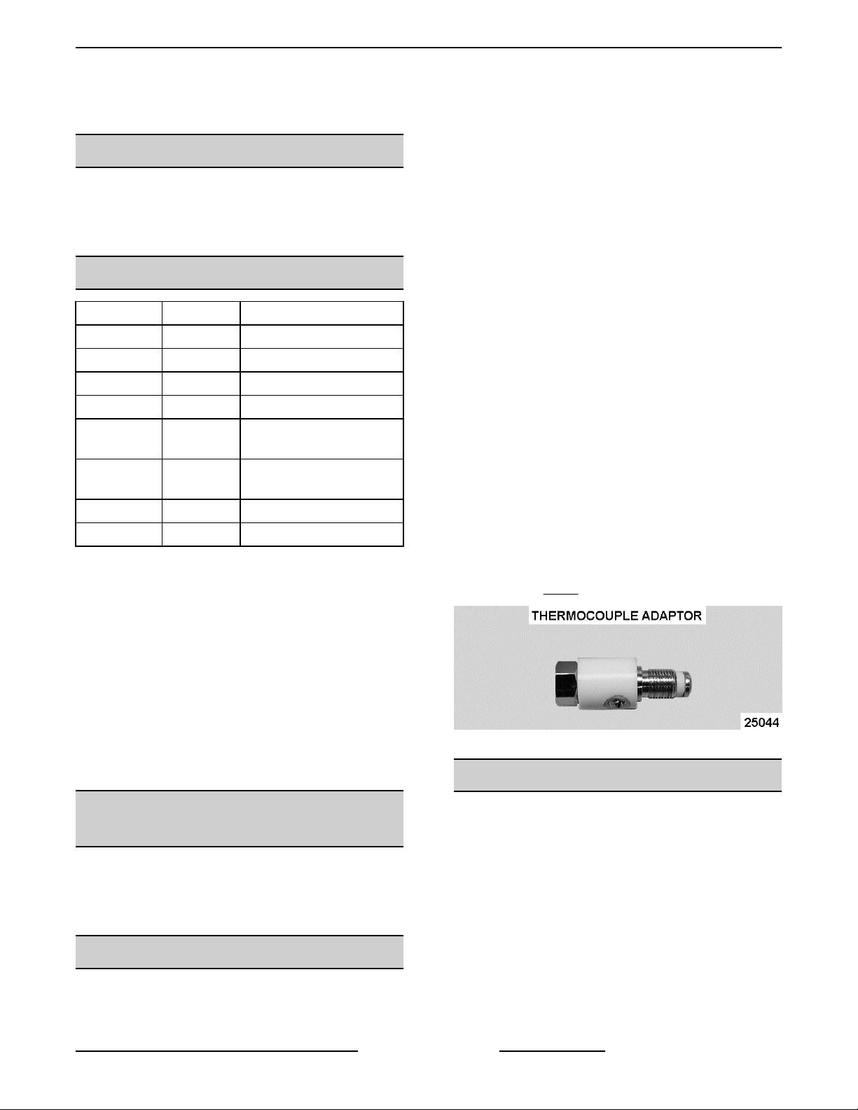
• Adaptor to test thermocouple closed circuit DC
voltages (purchase locally). Adaptors vary
between manufacturers. Example of one adaptor
type is in
Fig. 1.
Propane: 10 in. W. C.
Inlet Supply Pressure
Natural - Recommended 7 in. W. C.; Minimum 5
•
in. W. C.
• Propane - Recommended 11 in. W. C. ; Minimum
11 in. W. C.
• Maximum 14 in. W.C. (0.5 PSI) (Natural or
Propane)
INSTALLATION, OPERATION AND
CLEANING
For detailed installation, operation and cleaning
instructions, refer
unit. The manual is also available online at
www.vulcanequipment.com.
to Instruction manual sent with each
TOOLS
Standard
• Standard set of hand tools.
Fig. 1
LUBRICATION
Anderson and Forrester (or comparable) valve grease
for top burner gas valves, top burner pilot valves, and
pressure tap plugs. Apply light coat to valve/plugs.
Apply light coat to valve/plug threads, Valve grease
must be insoluble in propane and natural gas.
Page 3 of 27 F45992 (1123)
Page 4
WX RANGE - 2. REMOVAL AND REPLACEMENT PARTS
2. REMOVAL AND REPLACEMENT PARTS
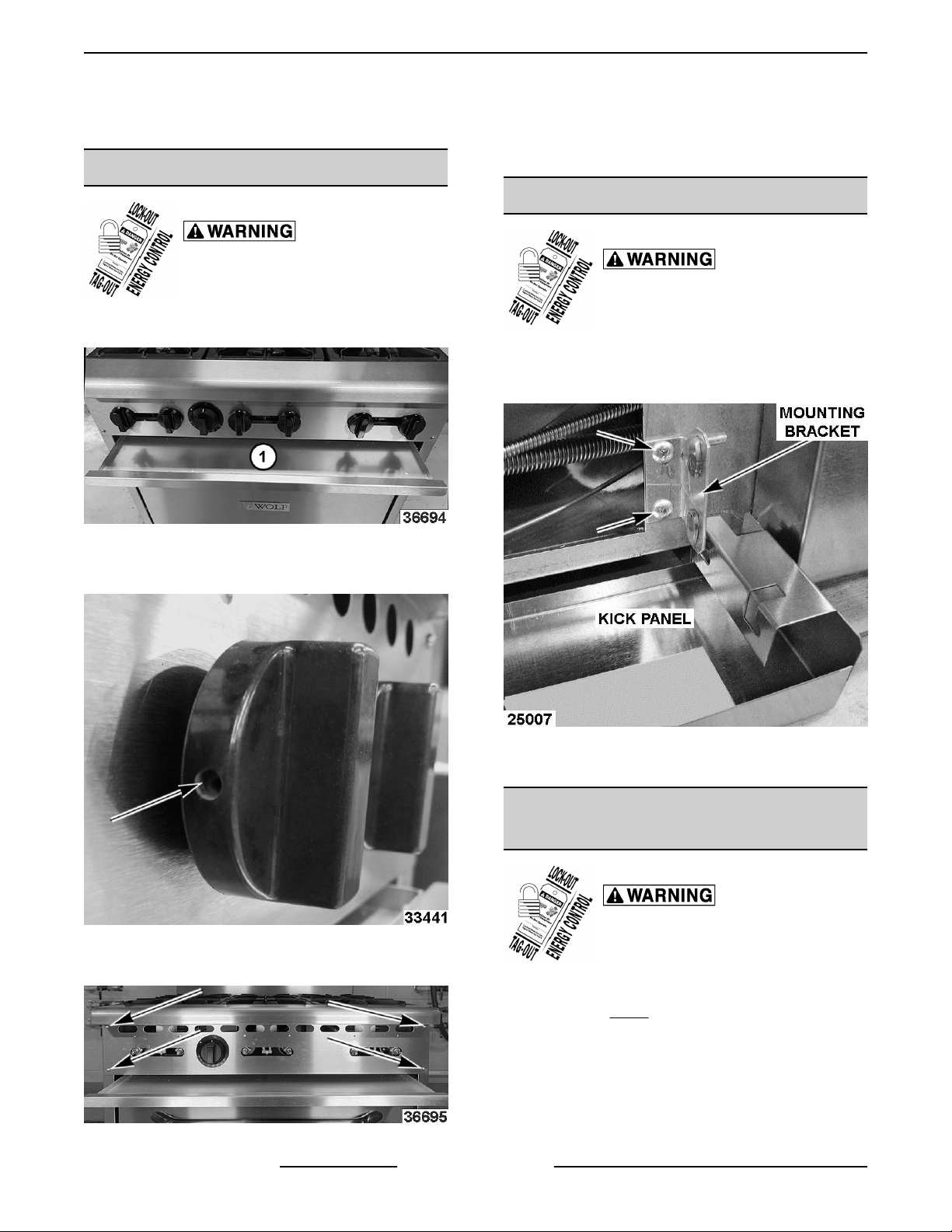
MANIFOLD COVER
Shut off the gas before servicing the
unit and follow lockout / tagout
procedures.
Pull crumb tray out.
1.
Fig. 2
2. Loosen set screws in top burner control knobs
and remove knobs.
4. Reverse procedure to install.
KICK PANEL
Shut off the gas before servicing the
unit and follow lockout / tagout
procedures.
1. Lift
2. Remove kick panel mounting bracket.
up on kick panel and rotate down 90 degrees.
3. Reverse procedure to install.
ASSEMBLY
Fig. 3
3.
Remove manifold mounting screws.
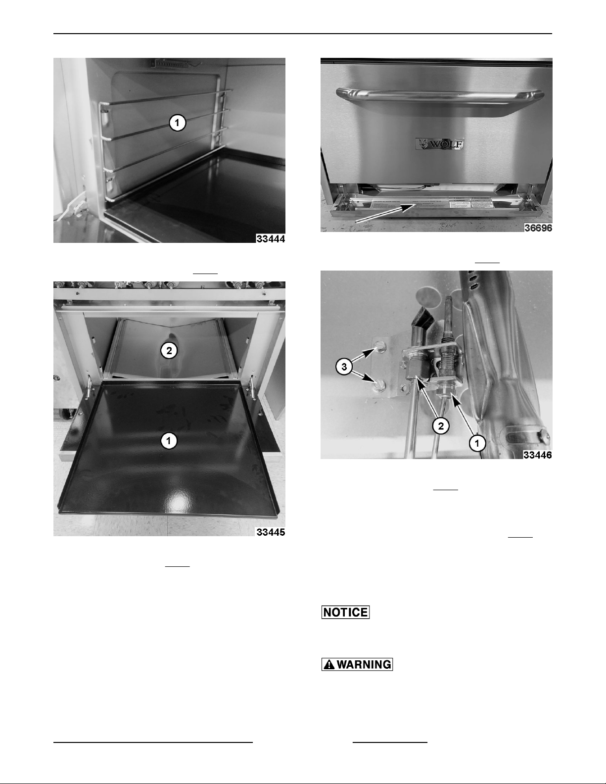
1. Remove oven racks. Lift up and pull out rack
Fig. 4
F45992 (1123) Page 4 of 27
Fig. 5
STANDARD OVEN PILOT
AND THERMOCOUPLE
Shut off the gas before servicing the
unit and follow lockout / tagout
procedures.
guides (1, Fig. 6).
Page 5
WX RANGE - 2. REMOVAL AND REPLACEMENT PARTS
Fig. 6
2. Lift cavity bottom panel (1, Fig. 7) and slide out.
Fig. 8
5. Remove thermocouple nut (1, Fig. 9).
3.
Remove V baffle (2,
4.
Lower kick panel.
Fig. 7
Fig. 7).
Fig. 9
6.
Remove pilot nut (2,
NOTE: Take care not to lose pilot orifice after
removing nut.
7.
Remove mounting bracket screws (3,
remove pilot oven assembly.
NOTE:
tubing and thermocouple from oven pilot assembly.
8. Reverse procedure to install.
When installing, do not bend and kink the capillary
tube or damage to the component may occur.
All gas joints disturbed during servicing must be
checked for leaks. Check with a soap and water
solution (bubbles). Do not use an open flame.
9.
Page 5 of 27 F45992 (1123)
If replacing oven pilot assembly , remove pilot
Verify operation.
Fig. 9).
Fig. 9) to
Page 6
WX RANGE - 2. REMOVAL AND REPLACEMENT PARTS
STANDARD OVEN BURNER &
ORIFICE HOOD
Shut off the gas before servicing the
unit and follow lockout / tagout
procedures.
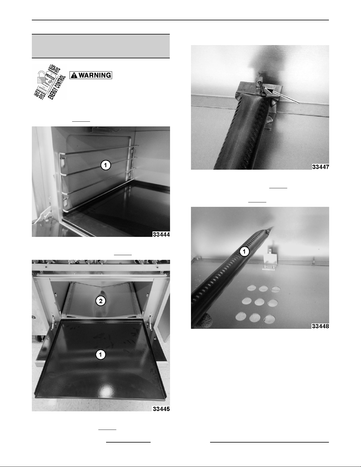
Remove oven racks. Lift up and pull out rack
1.
guides (1,
Fig. 10).
4. Remove cotter pin.
Fig. 12
5. Lift up back of burner (1, Fig. 13) and move
burner toward rear of oven to disengage from
burner orifice (2, Fig. 12).
Fig. 10
2. Lift cavity bottom panel (1, Fig. 11) and slide out.
Fig. 13
Fig. 11
3.
Remove V baffle (2,
F45992 (1123) Page 6 of 27
Fig. 11).
Page 7
WX RANGE - 2. REMOVAL AND REPLACEMENT PARTS
Fig. 16
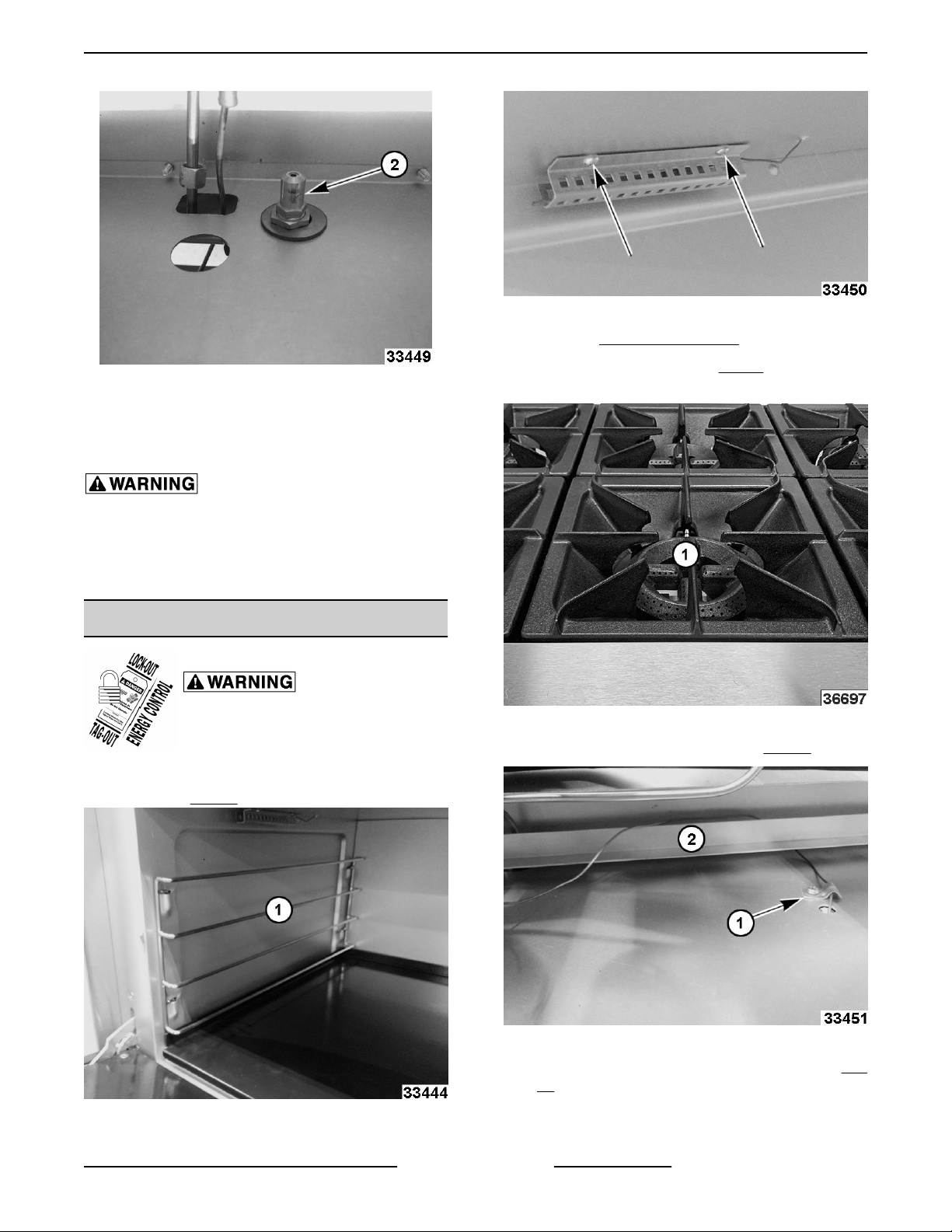
3. Remove MANIFOLD COVER.
Fig. 14
6. If applicable, unscrew orifice hood mounting nut
to remove orifice.
7. Reverse procedure to install.
All gas joints disturbed during servicing must be
checked for leaks. Check with a soap and water
solution (bubbles). Do not use an open flame.
8. Verify proper operation.
OVEN THERMOSTAT
Shut off the gas before servicing the
unit and follow lockout / tagout
procedures.
1. Remove oven racks. Lift up and pull out rack
guides (1, Fig. 15).
4. Remove burner grates (1, Step 4) as needed to
access capillary tube.
Fig. 17
5. Remove capillary tube clamp (1, Fig. 18).
Fig. 15
2. Remove capillary bulb cover.
Fig. 18
6. Remove capillary
18).
7. Roll capillary tube up.
Page 7 of 27 F45992 (1123)
tube from around guard (2,
Fig.
Page 8
WX RANGE - 2. REMOVAL AND REPLACEMENT PARTS
NOTE: Rolling capillary tube up will allow clearance
turn/rotate thermostat valve assembly off manifold.
to
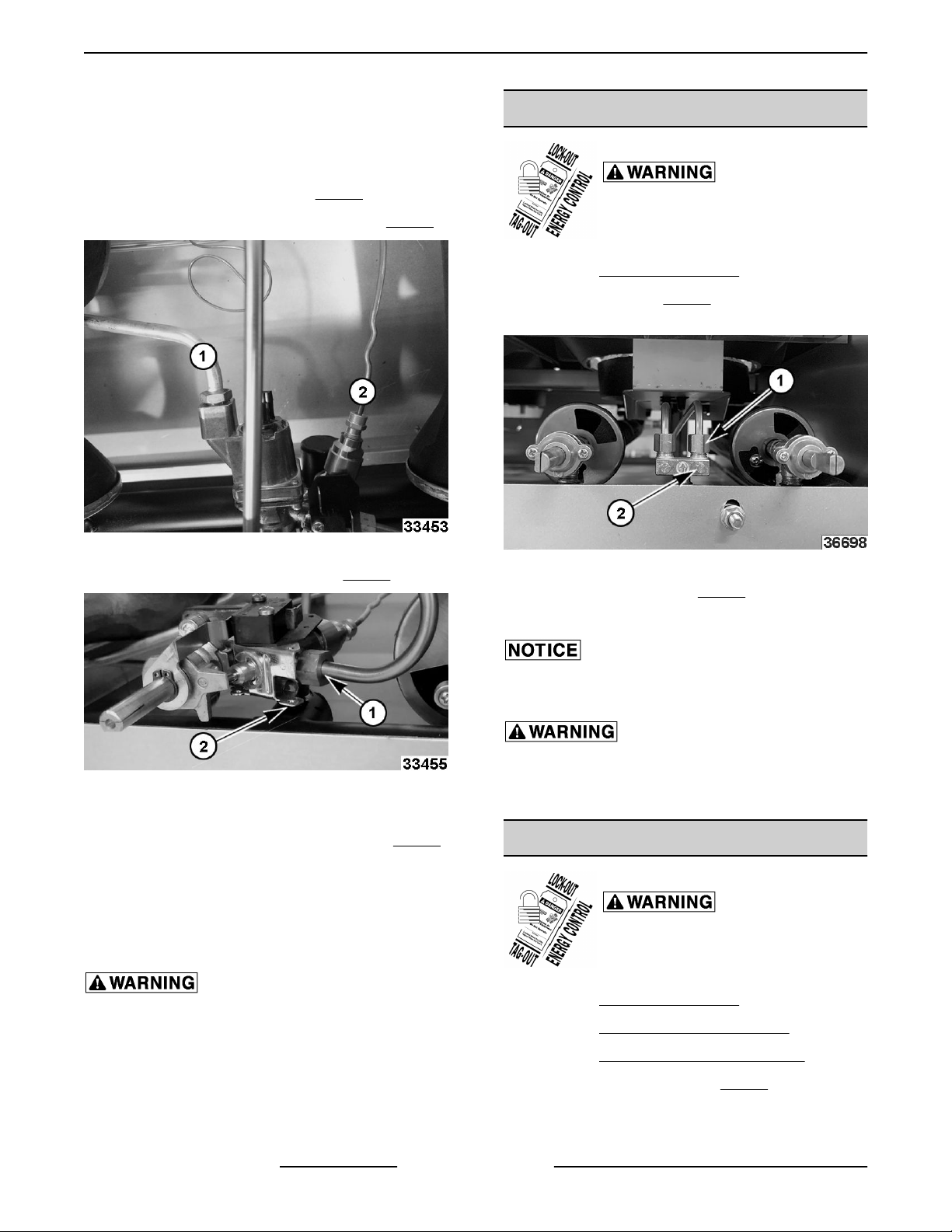
8. Disconnect thermostat valve assembly
connections.
A. Gas outlet to burner (1,
Thermocouple to oven burner. (2,
B.
Fig. 19
9. Disconnect gas outlet to pilot (1, Fig. 20).
Fig. 19).
Fig. 19)
TOP BURNER PILOT VALVE
Shut off the gas before servicing the
unit and follow lockout / tagout
procedures.
Remove
1.
Remove fitting (1,
2.
pilot valve.
3. Unscrew pilot valve (2, Fig. 21) from manifold.
MANIFOLD COVER.
Fig. 21) securing pilot tube to
Fig. 21
Fig. 20
10.
Roll capillary tube up.
11. Unscrew thermostat valve assembly (2,
off manifold.
NOTE: Depending on range options, some will have
additional valves on either side that may need
removed for clearance to remove thermostat valve.
12.
Reverse procedure to install.
All gas joints disturbed during servicing must be
checked for leaks. Check with a soap and water
solution (bubbles). Do not use an open flame.
Fig. 20)
4. Reverse procedure to install.
Do not over tighten pilot valve or damage to the
threads may occur.
All gas joints disturbed during servicing must be
checked for leaks. Check with a soap and water
solution (bubbles). Do not use an open flame.
TOP BURNER CONTROL VALVE
Shut off the gas before servicing the
unit and follow lockout / tagout
procedures.
1. Remove MANIFOLD COVER.
2. Remove TOP BURNER ASSEMBLY.
3. Remove TOP BURNER PILOT VALVE.
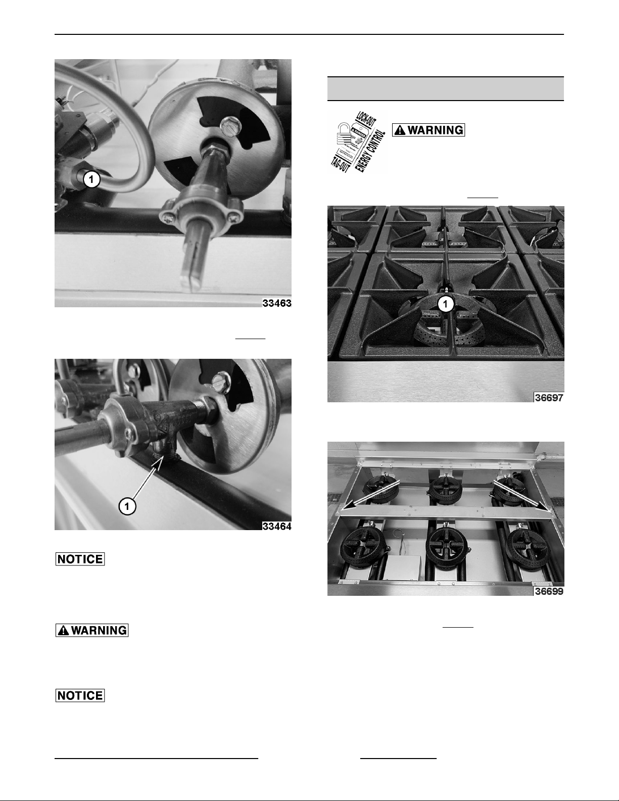
4. Disconnect pilot tubing (1, Fig. 22) from
F45992 (1123) Page 8 of 27
thermostat assembly for clearance if needed.
Page 9
WX RANGE - 2. REMOVAL AND REPLACEMENT PARTS
7. Verify proper operation.
TOP BURNER ASSEMBLY
Shut off the gas before servicing the
unit and follow lockout / tagout
procedures.
Remove burner grates (1,
1.
Fig. 22
Fig. 24).
5. Remove top burner control valve (1, Fig. 23) from
manifold.
Fig. 23
Inspect top control valve for wear or damage and
replace as necessary.
6.
Reverse procedure to install.
Fig. 24
2. Remove center burner grate support.
Fig. 25
3.
Lift burner heads (1,
Fig. 26) off.
All gas joints disturbed during servicing must be
checked for leaks. Check with a soap and water
solution (bubbles). Do not use an open flame.
Ensure top burner control valve is aligned and
centered in the burner assembly opening. The valve
must be perpendicular to the manifold.
Page 9 of 27 F45992 (1123)
Page 10
WX RANGE - 2. REMOVAL AND REPLACEMENT PARTS
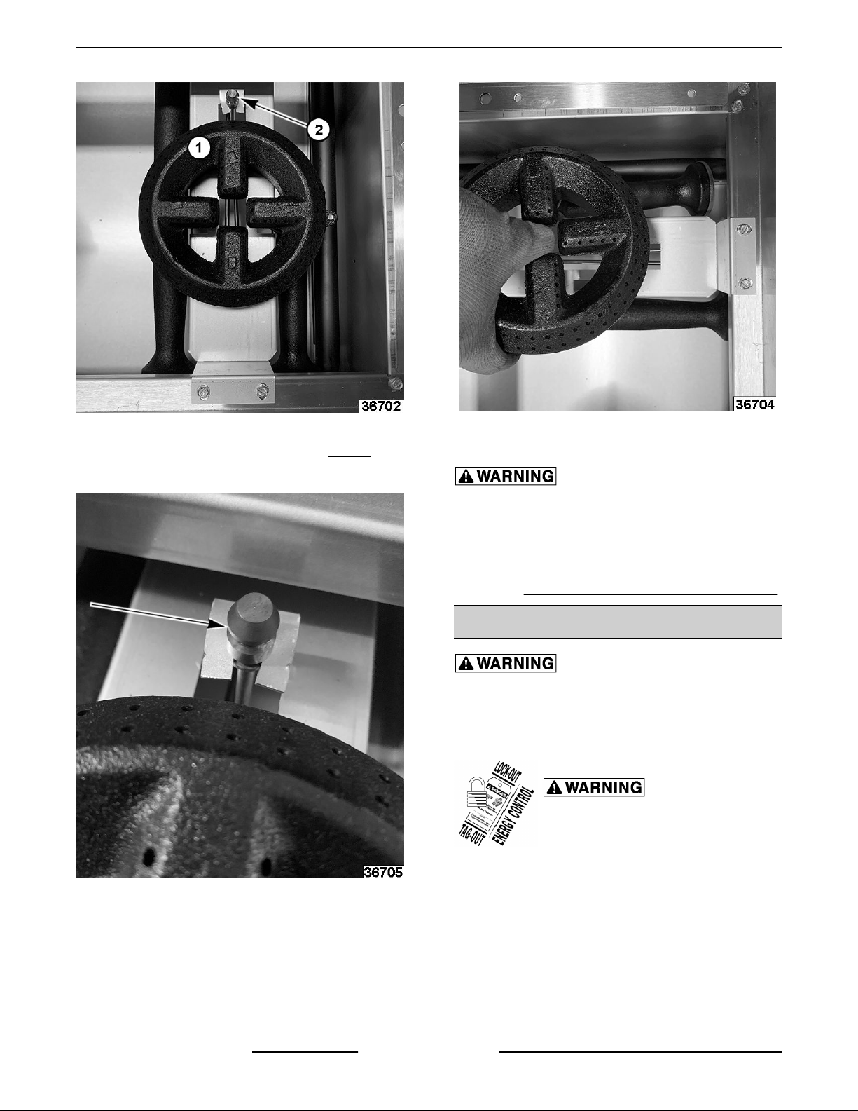
Fig. 26
4. Remove burner retainer bracket (2, Fig. 26).
5. Unclip pilot.
Fig. 28
7. Reverse procedure to install.
All gas joints disturbed during servicing must be
checked for leaks. Check with a soap and water
solution (bubbles). Do not use an open flame.
8. Verify proper operation.
9. Verify BURNER AIR SHUTTER ADJUSTMENT.
OVEN DOOR
When servicing hinges, use cut resistant glove
with additional padding to compress hinge to
insert bolt into slot or remove bolt after door is
removed.
Shut off the gas before servicing the
unit and follow lockout / tagout
procedures.
Remove Door
Fig. 27
6. Lift
F45992 (1123) Page 10 of 27
top burner assembly at the rear and pull away
from front manual valves.
1.
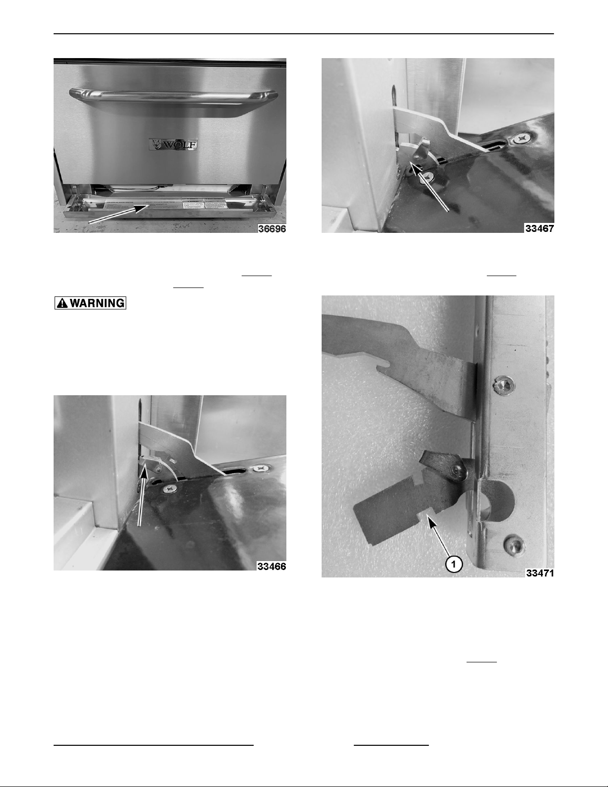
Lower kick panel (1,
Fig. 29).
Page 11
WX RANGE - 2. REMOVAL AND REPLACEMENT PARTS
Fig. 29
2. Open door enough to move left and right safety
latches from the disengaged position (Fig. 30) to
the engaged position (Fig. 31).
Hold both sides of door when engaging safety
latches on the locking lever. After safety latches
are in the engaged position, hold the door and do
not open more angles. The safety latches will be
crushed easily if any force pushes down the door
at that moment.
Fig. 31
3. Lift up on door, while holding both sides, to
disengage locking lever notch (1, Fig. 32) on both
sides.
Fig. 30
Fig. 32
A.
Release notch on the swivel hinge, from
bottom edge of the door hinge stop to
remove door.
B. Release spring loaded hinge from the roller
and pin inside the slot (
hinge stop to remove door.
Page 11 of 27 F45992 (1123)
Fig. 34) on door
Page 12
WX RANGE - 2. REMOVAL AND REPLACEMENT PARTS
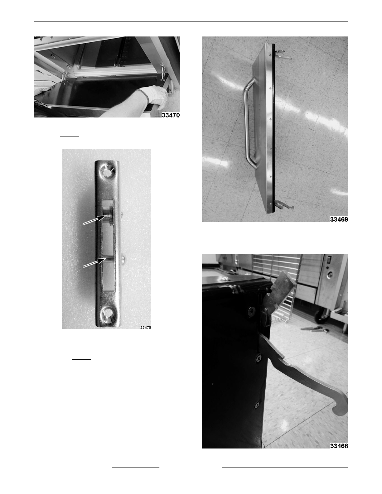
Fig. 33
NOTE: Fig. 34 shows bracket with pin and roller
inside slot not mounted in oven frame for clarity.
Remove Hinge
1.
Remove
2.
Stabilize door on floor.
DOOR.
Fig. 35
3. Press against spring loaded arm to release
safety latch.
Fig. 34
F45992 (1123) Page 12 of 27
Fig. 36
Page 13
WX RANGE - 2. REMOVAL AND REPLACEMENT PARTS
4. Remove screws out of door hinges to separate
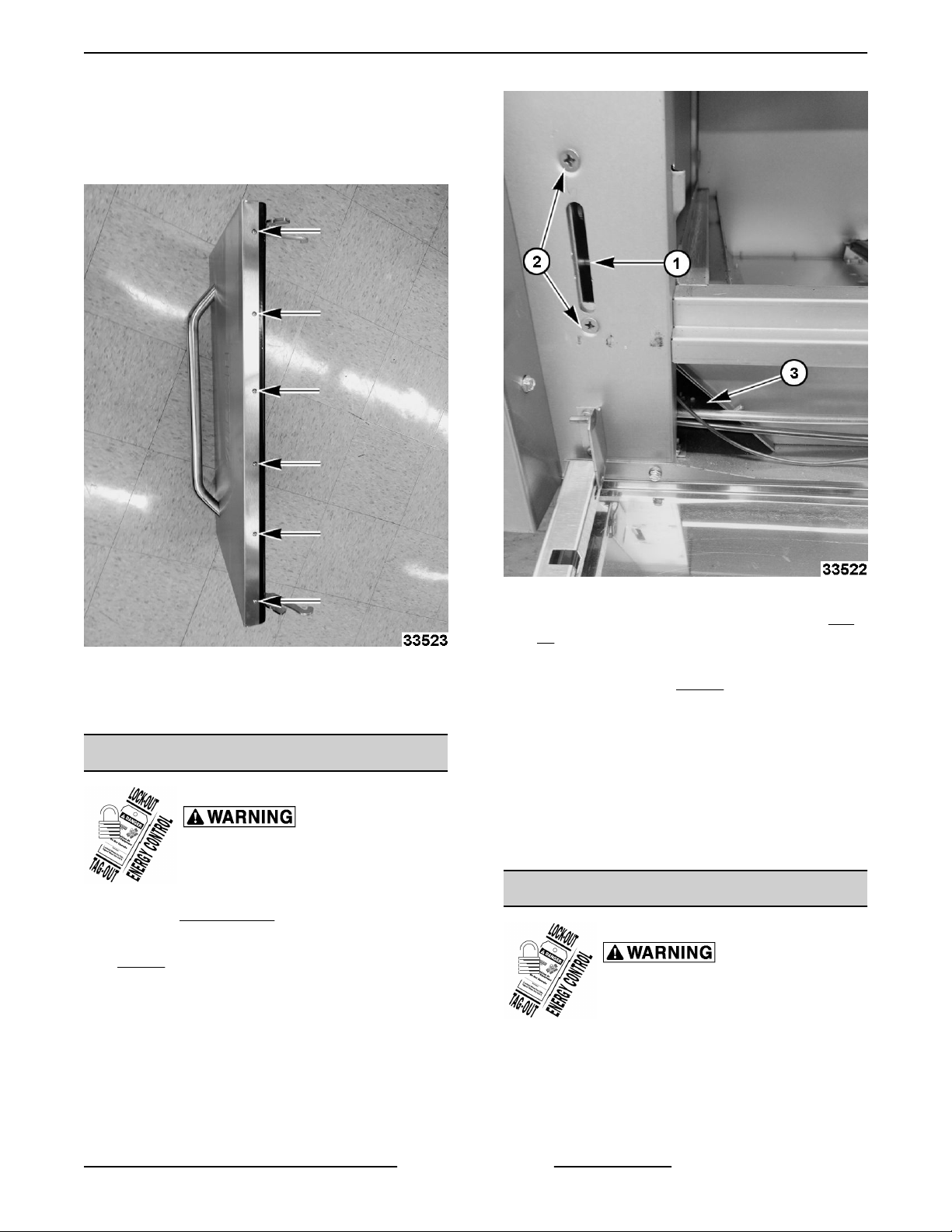
door.
Remove inner door panel mounting screws and
5.
separate from door.
Fig. 37
6. Remove hinges.
7. Reverse procedure to install.
DOOR STOP
Shut off the gas before servicing the
unit and follow lockout / tagout
procedures.
1. Remove OVEN DOOR.
2. Tie string or flexible wire around pin or roller (1,
Fig. 38).
NOTE: Holding onto string/wire while removing stop
will secure it from failing down into oven cavity.
Fig. 38
3. Remove stop bracket from oven frame (2, Fig.
38).
4. Slide stop bracket down cavity channel and out
through opening (3, Fig. 38).
5. Tie string or flexible wire around pin or roller on
new bracket to assist installation up through
cavity channel.
6. Align oven frame and stop bracket mounting
holes and install screws.
7. Reverse procedure to install.
8. Verify door operation.
GAS PRESSURE REGULATOR
Shut off the gas before servicing the
unit and follow lockout / tagout
procedures.
1. Access gas pressure regulator on back of range.
2. Remove regulator access cap.
Page 13 of 27 F45992 (1123)
Page 14
WX RANGE - 2. REMOVAL AND REPLACEMENT PARTS
Fig. 41
3. Verify proper operation.
Fig. 39
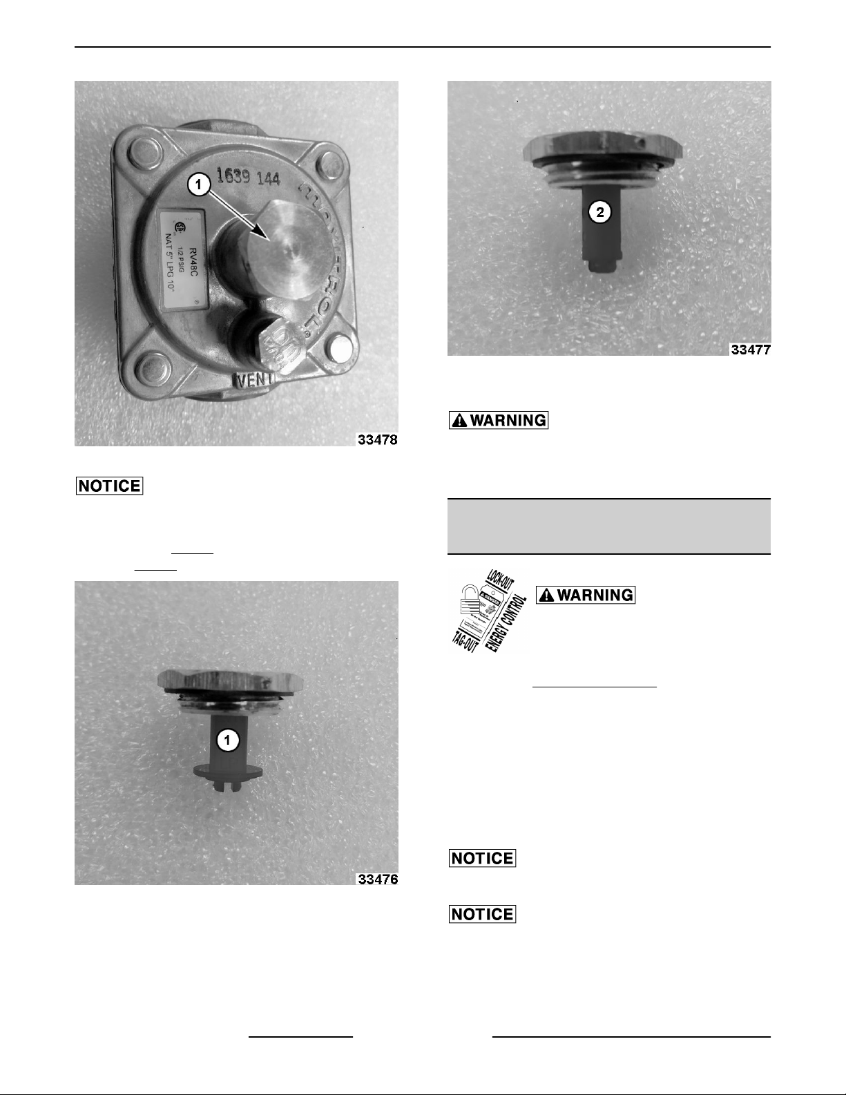
Regulator piston is installed in different directions for
type of gas being used. Turn upside down to change
directions. 1, in Fig. 40, shows direction for propane
gas. 2, in Fig. 41 shows direction for natural gas.
All gas joints disturbed during servicing must be
checked for leaks. Check with a soap and water
solution (bubbles). Do not use an open flame.
GRIDDLE PILOT ASSEMBLY AND
THERMOCOUPLE
Shut off the gas before servicing the
unit and follow lockout / tagout
procedures.
1. Remove MANIFOLD COVER.
2. Remove pilot assembly mounting bracket to
griddle burner box.
3. Remove pilot assembly mounting screws to
bracket.
4. If replacing pilot assembly, remove pilot tubing
and thermocouple frolm pilot assembly.
5. Reverse procedure to install.
Fig. 40
F45992 (1123) Page 14 of 27
Do not bend or kink capillary tube.
Verify orifice hood is aligned and centered with burner
assembly opening.
Page 15
WX RANGE - 2. REMOVAL AND REPLACEMENT PARTS
GRIDDLE BURNER ORIFICE HOOD
Shut off the gas before servicing the
unit and follow lockout / tagout
procedures.
Remove
1.
Remove orifice hood from fitting.
2.
3. Reverse procedure to install.
Verify orifice hood is aligned and centered with burner
assembly opening.
MANIFOLD COVER.
Page 15 of 27 F45992 (1123)
Page 16
WX RANGE - 3. SERVICE PROCEDURES, TEST AND ADJUSTMENTS
3. SERVICE PROCEDURES, TEST AND
ADJUSTMENTS
TOP BURNER PILOT ADJUSTMENT
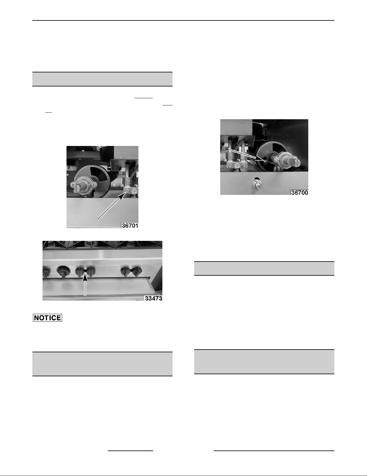
1. Locate pilot adjustment screw (1, Fig. 42)
through
43).
•
• Rotate counterclockwise to increase flame
the access hole in manifold cover (1,
Rotate clockwise to decrease flame height.
height.
Fig. 42
Fig.
• Yellow flame is indication of insufficient primary
air.
• White-blue
air.
1. Loosen shutter screw.
2. Rotate air shutter open until flame begins to lift
from burner.
3. Close the shutter slightly and tighten shutter
screw.
NOTE: The factory default air shutter positions are
half open natural; full open propane.
flame is a result of excessive primary
Fig. 44
Fig. 43
On range models with a thermocouple, the pilot burner
flame should surround and cover an area of at least
3/8" to 1/2" of the thermocouple at the hot tip end.
BURNER AIR SHUTTER
ADJUSTMENT
The efficiency of the burner depends on a delicate
balance between the air supply and volume of gas.
Whenever this balance is disturbed, poor operating
characteristics and excessive gas consumption may
occur.
An air shutter on the front of the burner controls
the gas mixer balance.
• Proper flame should be blue in color, well-defined
and seated on the burner port.
BURNER NOZZLE CHECK
NOTE: The burner nozzle is mounted between the
oven gas supply tubing/mounting bracket and the uburner assembly. If burner operation seems poor and
other systems have been checked, access the burner
for the range section being serviced and remove the
burner nozzle.
1. Check for blockage or damage.
2. Verify gas orifice hood is correct for the altitude.
OVEN THERMOSTAT BY-PASS
FLAME ADJUSTMENT
NOTE: The bypass flame setting has a direct affect
on calibration, and must be verified prior to checking
or adjusting calibration of any "modulating
thermostat". The by-pass flame can be viewed
through the kick panel for adjustment.
F45992 (1123) Page 16 of 27
Page 17
WX RANGE - 3. SERVICE PROCEDURES, TEST AND ADJUSTMENTS
All burners on the device must be on during by-pass
flame adjustment.
Turn thermostat knob to 375°F.
1.
2. Wait 15 minutes for oven to heat up.
3. Turn thermostat knob to lowest oven setting. DO
NOT TURN OFF.
4. Observe burner flame. The flame should be
approximately 1/8" and stable on each port.
Fig. 46
7. Replace thermostat knob.
8. Turn knob to 400°. Verify increase in flame height
on burner ports.
Fig. 45
By-Pass Flame Shown in Fig. 45
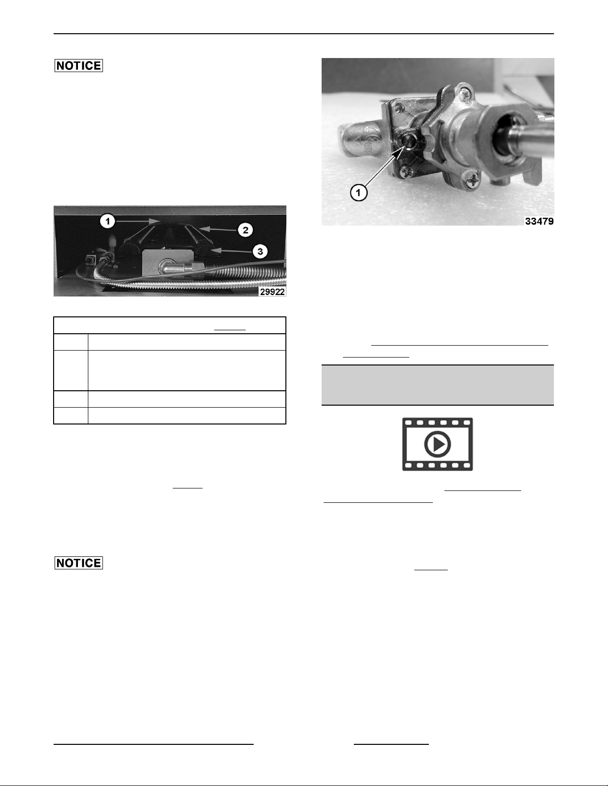
Item Description
Gap in flame, or some flickering fo the flame
1
is acceptable, only in the U-shape bend of
the burner.
2 By-Pass flame.
3 Oven burner.
5. Remove thermostat knob.
6. Adjust by-pass flame.
NOTE: With small flat edge screwdriver, turn by-pass
flame adjustment screw (1, Fig. 46) or ports should be
set to just above “flickering”.
• Counterclockwise to increase by-pass
flame.
• Clockwise to decrease flame.
Both legs of burner should have approximately 1/8"
stable flame on each port.
9. Turn knob back to lowest oven setting. Verify
decrease in by-pass flame height on burner ports
and that burner remains lit.
10. Verify OVEN THERMOSTAT TEMPERATURE
CALIBRATION.
OVEN THERMOSTAT
TEMPERATURE CALIBRATION
NOTE: Video available for Oven Thermostat
Temperature Adjustment.
1. Pull oven temperature knob off.
2. Separate the knob from the stem.
3. Check oven temperature using temperature
tester. Refer to: TOOLS.
4. Rotate knob left or right to temperature test
reading and slide onto stem.
NOTE: If needed, loosen dial screws, rotate the dial
to match temperature test reading and tighten screws.
Page 17 of 27 F45992 (1123)
Page 18
WX RANGE - 3. SERVICE PROCEDURES, TEST AND ADJUSTMENTS
Pilot Checks
If experiencing pilot outages, perform the following:
Visually check pilot flame for the proper contact on
thermocouple and adjust STANDARD OVEN PILOT
ASSEMBLY AND THERMOCOUPLE . If adjustment
does not result in a pilot flame of proper height, then
gas might not be flowing properly to the pilot.
Check for:
A plugged pilot orifice.
•
• Kinked or plugged pilot gas tubing.
• Low gas supply pressure.
Thermocouple Checks
NOTE: Tubing connection from the thermocouple tip
to gas safety valve is an electrical connection and
must be clean and dry. Do not use any sealing
compound on the threads of thermocouple nut.
Fig. 48
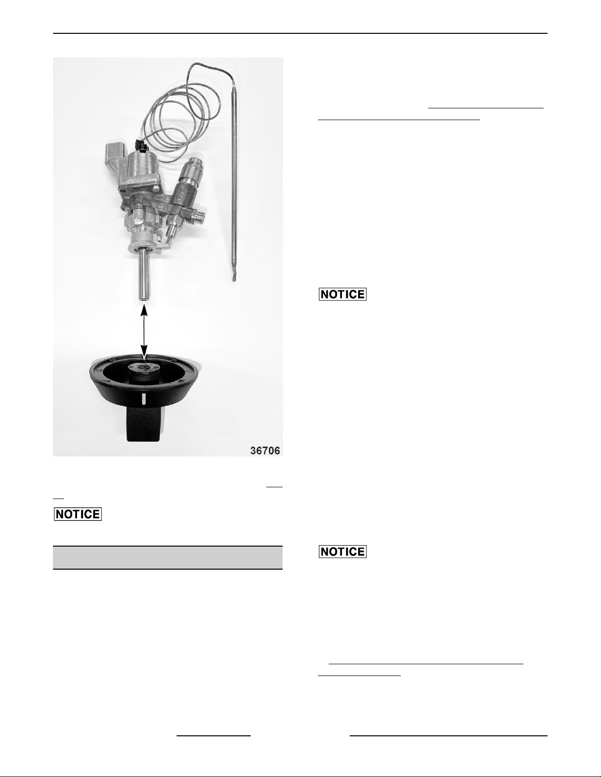
NOTE: Current production thermostat assembly (Fig.
48) shown not assembled to oven for clarity.
Verify flats on knob and stem align.
THERMOCOUPLE TEST
Operation
The thermocouple supplies a DC millivolt signal (MV)
to gas safety valve when heated by pilot flame. The
gas safety valve will shut off gas flow to pilot and main
burner in case of a pilot outage. When energized by
thermocouple voltage, the gas safety valve is held
open to permit gas flow to pilot and provide gas for
burner when thermostat calls for heat. Height of pilot
flame is controlled by an adjustable needle valve
located under a small cover screw on the gas safety
valve.
Do not overtighten the thermocouple nut or the
insulator could be crushed, shorting the
thermocouple.
a wrench only.
If pilot flame is correct and there are no excessive air
drafts in the room, then problem is either the
thermocouple output voltage or the gas safety valve.
Visually check the thermocouple tip (hot end) and tube
lead for:
• Loose thermocouple connection (electrical) at
the safety valve.
• Corrosion or debris on the threaded connector or
thermocouple tip causing a poor electrical
connection.
• Kinks or pinches that might cause a short
between the tube and the wire inside.
If thermocouple is loose, tighten mounting nut.
Do not overtighten the thermocouple nut or the
insulator could be crushed, shorting the
thermocouple.
a wrench only.
If thermocouple connection shows signs of corrosion
or debris that cannot be cleaned; or damage as
described, replace it and check pilot operation. Refer
to
STANDARD OVEN PILOT ASSEMBLY AND
THERMOCOUPLE.
Thermocouple Test
the thermocouple output voltage (DC millivolts)
Check
with a VOM as outlined in the steps below.
Finger tighten the nut plus 1/4 turn with
Finger tighten the nut plus 1/4 turn with
F45992 (1123) Page 18 of 27
Page 19
WX RANGE - 3. SERVICE PROCEDURES, TEST AND ADJUSTMENTS
• If thermocouple adaptor (see TOOLS) is
available,
in the test procedure.
• If thermocouple adaptor is not available, check
open circuit voltage as outlined in the test
procedure.
• If a VOM is not available, replace the
thermocouple with a new one as outlined under
the appropriate procedure below and check
operation. Refer to
ASSEMBLY AND THERMOCOUPLE
1. Disconnect
2. Select the test to perform.
3. Closed Circuit.
A. Install thermocouple adaptor at the
B. Install thermocouple to the adaptor.
Do not overtighten the thermocouple nut or the
insulator could be crushed, shorting the
thermocouple.
a wrench only.
check closed circuit voltage as outlined
STANDARD OVEN PILOT
thermocouple from gas safety valve.
threaded connection on gas safety valve.
Finger tighten the nut plus 1/4 turn with
If a VOM is not available, replace the
thermocouple with a new one as outlined under
the appropriate procedure below and check
operation.
• STANDARD OVEN PILOT ASSEMBLY
AND THERMOCOUPLE
Check for proper operation.
6.
C. Light the pilot. Allow pilot to heat
thermocouple for one to two minutes.
D. Connect one meter lead to the adaptor test
point and the other meter lead to the tube.
Compare reading to the value listed in the
table below.
4. Open Circuit.
A. Connect one meter lead to the tip of the
threaded end and the other meter lead to the
tube. Compare reading to the values listed
in the table below.
B. Light the pilot and continue to hold down the
pilot gas button on the safety valve during
this test. Allow pilot to heat thermocouple for
one to two minutes.
C. Compare reading to the value listed in the
table below.
THERMOCOUPLE MV READINGS
Closed Circuit Open Circuit
Range 8 to 25 MV 25 to 35 MV
5. If readings are less than the minimum stated
above, replace the thermocouple as outlined
under the appropriate procedure below and
check for proper operation.
Page 19 of 27 F45992 (1123)
Page 20

4. FIRMWARE / SOFTWARE
FIRMWARE / SOFTWARE
Not applicable to this machine.
WX RANGE - 4. FIRMWARE / SOFTWARE
F45992 (1123) Page 20 of 27
Page 21

PROGRAMMING
Not applicable to this machine.
WX RANGE - 5. PROGRAMMING
5. PROGRAMMING
Page 21 of 27 F45992 (1123)
Page 22

WX RANGE - 6. ELECTRICAL OPERATION
F45992 (1123) Page 22 of 27
Page 23
WX RANGE - 6. ELECTRICAL OPERATION
6.. ELECTRICAL OPERATION
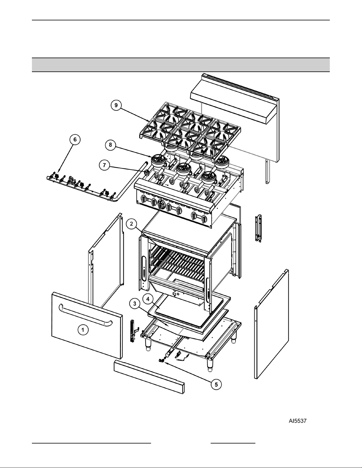
COMPONENT LAYOUT AND FUNCTION
Fig. 49
Page 23 of 27 F45992 (1123)
Page 24
WX RANGE - 6. ELECTRICAL OPERATION
Item Description
1 Door
2 Rack
3 V Baffle
4 Cavity Bottom Panel
5 Oven Pilot Assembly and Thermocouple
6 Manifold
7 Top Burner Valve Assembly
8 Burner
9 Grates
Burner Valve .......... Allows the flow of gas to the pilot light and burner.
Open Top Pilot ....... Small flame kept burning continuously to light range top burner.
Oven Pilot (Natural
Gas or Propane) ......
Thermostat Combo
Valve .................
Thermocouple ........ Provides milli-voltage signal to thermostat combo valve when heated by pilot flame.
Small flame kept burning continuously to light oven burner.
Flow control device to control the flow of gas to the oven with safety valve.
F45992 (1123) Page 24 of 27
Page 25

WX RANGE - 7. SEQUENCE OF OPERATION
7. SEQUENCE OF OPERATION
SEQUENCE OF OPERATION
Not applicable to this machine.
Page 25 of 27 F45992 (1123)
Page 26

DIAGRAMS
Not applicable to this machine.
WX RANGE - 8. DIAGRAMS
8. DIAGRAMS
F45992 (1123) Page 26 of 27
Page 27
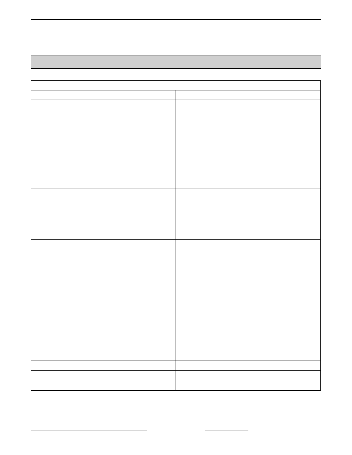
SYMPTOM POSSIBLE CAUSE
Oven does not remain lit.
WX RANGE - 9. TROUBLESHOOTING
9. TROUBLESHOOTING
TROUBLESHOOTING
GENERAL
1. Incorrect gas pressure.
2. Pilot burner not adjusted properly.
Pilot burner blocked.
3.
4. Thermocouple not positioned correctly or
malfunctioning.
5. Combination thermostat/safety valve malfunction.
6. Incorrect oven pilot orifice.
7. Ventilation issue in room (drafts blowing out pilot).
8. Defective burner, based on age of unit.
1. Gas supply is off.
2. Additional time needed to bleed air out of gas line.
Pilot not lighting.
Burner flame too yellow
Slow to heat or not hot enough.
Oven temperature too hot.
Low burner flame (all burners).
Low burner flame (individual burner). 1. Air mixture incorrect.
Flame floats on burner.
Low gas pressure.
3.
4. Pilot burner not adjusted properly.
5. Incorrect oven pilot orifice.
1. Orifice incorrect size or dirty.
2. Air shutter not adjusted correctly or dirty.
Incorrect gas pressure.
3.
4. Incorrect gas type.
5. Orifice misaligned in venturi.
6. Appliance not venting properly.
1. Low gas pressure.
2. Thermostat out of calibration.
1. Thermostat out of calibration.
2. By-pass flame to high.
1. Low gas pressure.
2. Incorrect gas type.
1. Inadequate air supply.
2. Restricted exhaust flue (ovens).
Page 27 of 27 F45992 (1123)
 Loading...