

Page 1
OWNER'S MANUAL
INSTALLATION & OPERATION
WKGD SERIES
GAS
CONVECTION OVENS
MODELS
WKGD ML-126621
For additional information on Wolf Range or to locate an authorized parts
and service provider in your area, visit our website at www.wolfrange.com
WOLF RANGE
DIVISION OF ITW FOOD EQUIPMENT GROUP, LLC
WWW.WOLFRANGE.COM
P.O. BOX 696
LOUISVILLE, KY 40201-0696
FORM 31133 Rev. E (Dec. 2007)
Page 2
IMPORTANT FOR YOUR SAFETY
THIS MANUAL HAS BEEN PREPARED FOR PERSONNEL QUALIFIED TO INSTALL GAS
EQUIPMENT, WHO SHOULD PERFORM THE INITIAL FIELD START-UP AND
ADJUSTMENTS OF THE EQUIPMENT COVERED BY THIS MANUAL.
POST IN A PROMINENT LOCATION THE INSTRUCTIONS TO BE FOLLOWED IN THE
EVENT THE SMELL OF GAS IS DETECTED. THIS INFORMATION CAN BE OBTAINED
FROM THE LOCAL GAS SUPPLIER.
IMPORTANT
IN THE EVENT A GAS ODOR IS DETECTED, SHUT DOWN
UNITS AT MAIN SHUTOFF VALVE AND CONTACT THE
LOCAL GAS COMPANY OR GAS SUPPLIER FOR
SERVICE.
FOR YOUR SAFETY
DO NOT STORE OR USE GASOLINE OR OTHER
FLAMMABLE VAPORS OR LIQUIDS IN THE VICINITY OF
THIS OR ANY OTHER APPLIANCE.
Improper installation, adjustment,
alteration, service or maintenance can cause property
damage, injury or death. Read the installation, operating
and maintenance instructions thoroughly before
installing or servicing this equipment.
IN THE EVENT OF A POWER FAILURE, DO NOT ATTEMPT
TO OPERATE THIS DEVICE.
© WOLF RANGE, 2005
– 2 –
Page 3
Installation, Operation and Care of
WKGD SERIES
GAS CONVECTION OVENS
KEEP THIS MANUAL FOR FUTURE REFERENCE
GENERAL
Wolf Range Gas Convection Ovens are produced with quality workmanship and material. Proper
installation, usage and maintenance of your oven will result in many years of satisfactory performance.
It is suggested that you thoroughly read this entire manual and carefully follow all of the instructions
provided.
Models WKGD Series feature a solid state temperature control. One-hour dial timer and buzzer and
two-speed
1
/2 HP (0.37 kw) blower motor are standard equipment. Porcelain interior is standard. The
burner input rating for each oven is 44,000 BTU/hr. Oven doors open independently (standard);
simultaneous door opening is optional. All ovens are furnished with 5 racks.
The standard 120 V, 60 Hz, 1 PH ovens include cord and plug. Optional electrical specifications require
hard wire connection.
Wolf Range offers a stacking kit for mounting one oven on top of another as an option. Other available
options include: five-hour timer, 208/240 V electrical service, additional oven racks and open stand with
lower storage rack and roast and hold.
FEATURES AND OPTIONS
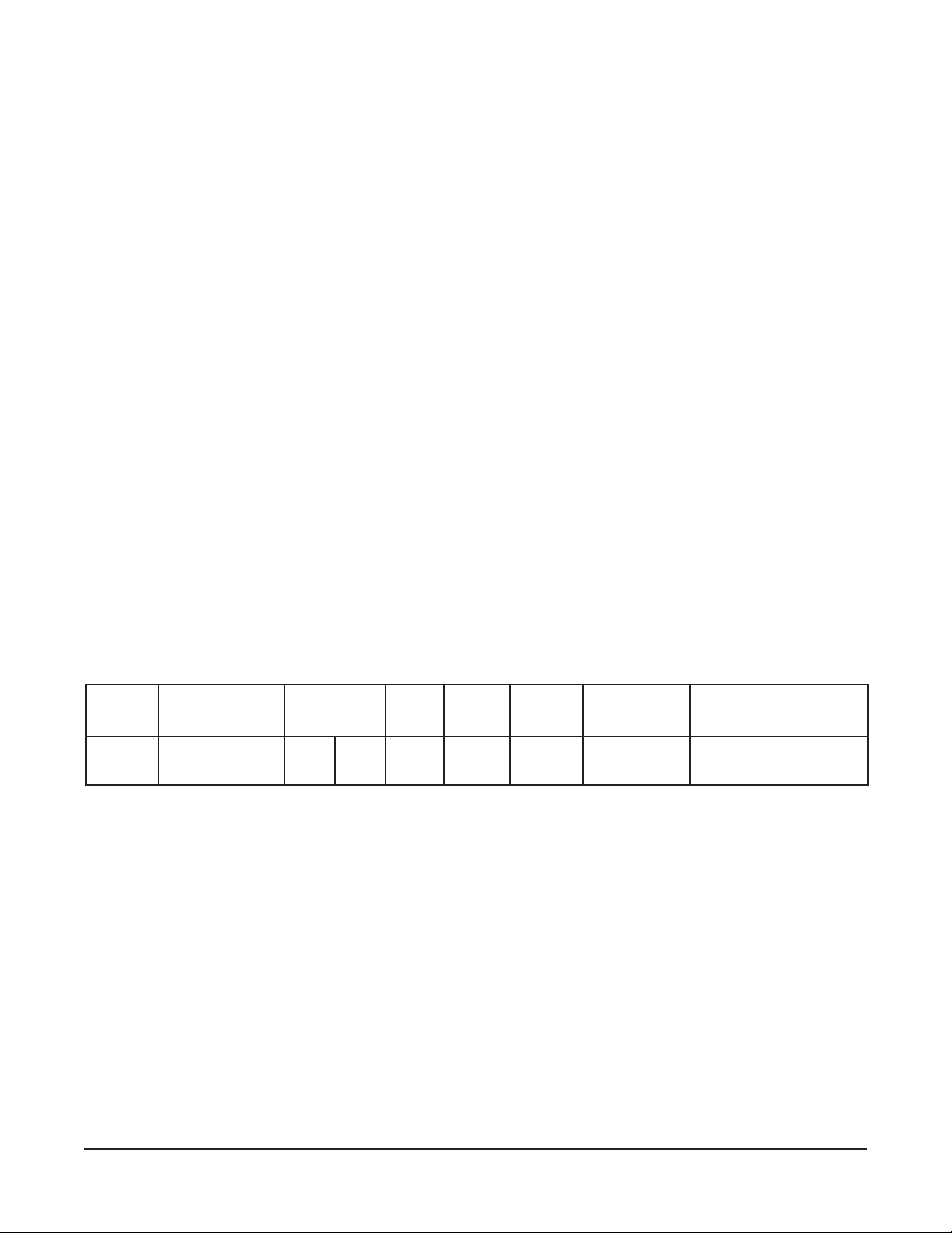
Model Thermostat Timer
WKGD Solid State
① ①
①
① ①
See ELECTRICAL CONNECTIONS section of this manual for additional optional voltage available.
1 Hr. 5 Hr.
Std. Opt. (654 mm)
Oven Roast &
Lights Hold Storage Rack
Std. Opt.
Legs
253/4
Stand with
Opt. 120/60/1 Std.
Voltage
①①
①
①①
INSTALLATION
Before installing, verify that the electrical service and type of gas supply (natural or L. P. gases) agree
with the specifications on the rating plate, located behind the top trim panel on the front of the oven. If
the supply and equipment requirements do not agree, do not proceed with the installation. Contact your
dealer or Wolf Range immediately.
UNPACKING
Immediately after unpacking, check for possible shipping damage. If the oven is found to be damaged,
save the packaging material and contact the carrier within 15 days of delivery.
Carefully unpack the oven and place in a work-accessible area near to its final installed position.
Do not use the doors or their handles to lift the oven.
– 3 –
Page 4

LOCATION
The equipment area must be kept free and clear of combustible substances.
When installed, minimum clearance from combustible construction must be 1 inch (25 mm) at the left
side, 4 inches (102 mm) at the right side and 6 inches
noncombustible construction must be 0 inch (0 cm) at the left side, 4 inches (102 mm) at the right side
and 6 inches (152 mm) at the rear. The oven may be installed on combustible floors.
The installation location must allow adequate clearances for servicing and proper operation. There
must be 18 inches (457 mm) of clearance on the right side of the oven from any open flame.
The oven must be installed so that the flow of combustion and ventilation air will not be obstructed.
Adequate clearance for air openings into the combustion chamber must be provided. Make sure there
is an adequate supply of air in the room to allow for combustion of gas at the oven burners.
Do not permit fans to blow directly at the oven. Wherever possible, avoid open windows next to the oven.
Avoid wall-type fans which create air cross currents within the room.
INSTALLATION CODES AND STANDARDS
In the United States of America:
1. State and local codes.
2. National Fuel Gas Code, ANSI/Z223.1/NFPA #54 (latest edition). Copies may be obtained from The
American Gas Association, Inc., Accredited Standards Committee Z223 @ 400 N. Capital St. NW,
Washington, DC 20001 or the Secretary Standards Council, NFPA, 1 Batterymarch Park, Quincy,
MA 02169-7471.
(152 mm) at the rear. Minimum clearance from
NOTE: In the Commonwealth of Massachusetts,
All gas appliances vented through a ventilation hood or exhaust system equipped with a damper or
with a power means of exhaust shall comply with 248 CMR.
3. Vapor Removal From Cooking Equipment
The National Fire Protection Association, Batterymarch Park, Quincy, MA 02169-7471.
4.
National Electrical Code, ANSI/NFPA-70 (latest edition). Copies may be obtained from The
National Fire Protection Association, Batterymarch Park, Quincy, MA 02169-7471.
In Canada:
1. Local codes.
2. CSA B149.1 Natural Gas and Propane Installation Code.
3. CSA C22.1 Canadian Electric Code (latest edition).
The above are available from the Canadian Standard Association, 5060 Spectrum Way, Suite 100,
Mississauga, Ontario, Canada L4W 5N6.
, NFPA-96 (latest edition). Copies may be obtained from
– 4 –
Page 5
INSTALLING BASIC OVEN
The basic oven must be installed on legs or be mounted on a modular stand. Installations on concrete
bases or other supports restricting air circulation underneath the oven is not advisable and may void
the warranty.
Ovens Mounted on Casters
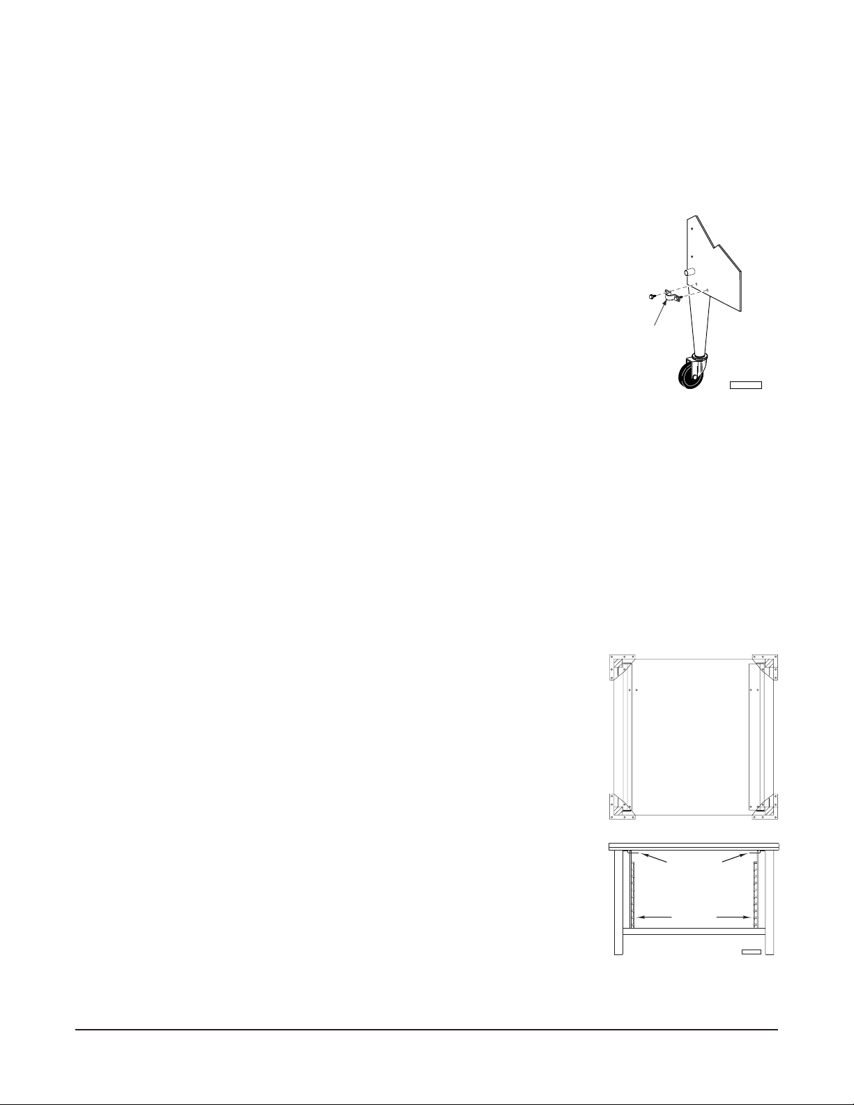
Ovens mounted on casters must use a flexible connector (not
supplied by Wolf) that complies with the Standard for Connectors
for Movable Gas Appliances, ANSI Z21.69 • CSA 6.16 and a quickdisconnect device that complies with the Standard for QuickDisconnect Devices for Use With Gas Fuel, ANSI-Z21.41 • CSA
6.9. In addition, adequate means must be provided to limit movement
of the appliance without depending on the connector and the quickdisconnect device or its associated piping to limit appliance
movement. Attach the restraining device at the rear of the oven as
shown in Fig. 1.
CONNECT
GAS LINE
STRAIN RELIEF
HERE
PL-53563
Remove two screws from the rear of the oven and install the tiedown strap shipped with the casters using these screws (Fig. 1).
Fig. 1
Attach the gas line strain relief to the tie-down strap at the rear of
the oven (Fig. 1).
If disconnection of the restraint is necessary, turn off the gas supply before disconnection. Reconnect
this restraint prior to turning the gas supply on and returning the oven to its installation position.
Separate instructions for installing casters to the oven are included with the casters.
Note: If the oven is installed on casters and is moved for any reason, it is recommended that the oven
be releveled front to back and side to side.
Assembling the Legs to the Oven
The legs must be installed on the bottom of the oven. Gently position the
BACK
oven on its side, taking care not to scratch or damage it.
Attach each of the four leg assemblies to the bottom of the oven with the
24 bolts and lockwashers (six per leg). Carefully raise the oven to its
normal position.
ASSEMBLING THE STAND TO THE OVEN
Attach each of the four leg assemblies to the bottom of the oven with the
FRONT
24 bolts and lockwashers (six per leg). Carefully raise the oven to its
normal position. Attach the undershelf to the legs with eight bolts and
lockwashers (two per leg).
RACK SUPPORT
Install the rack guides into the undershelf at desired locations (for pan or
flat rack), then attach the rack supports to the top end of the rack guides.
RACK GUIDE
Attach rack supports to the leg assembly by removing one middle bolt and
reattaching back through the end holes in the rack support (Fig. 2).
PL-56178
– 5 –
Fig. 2
Page 6
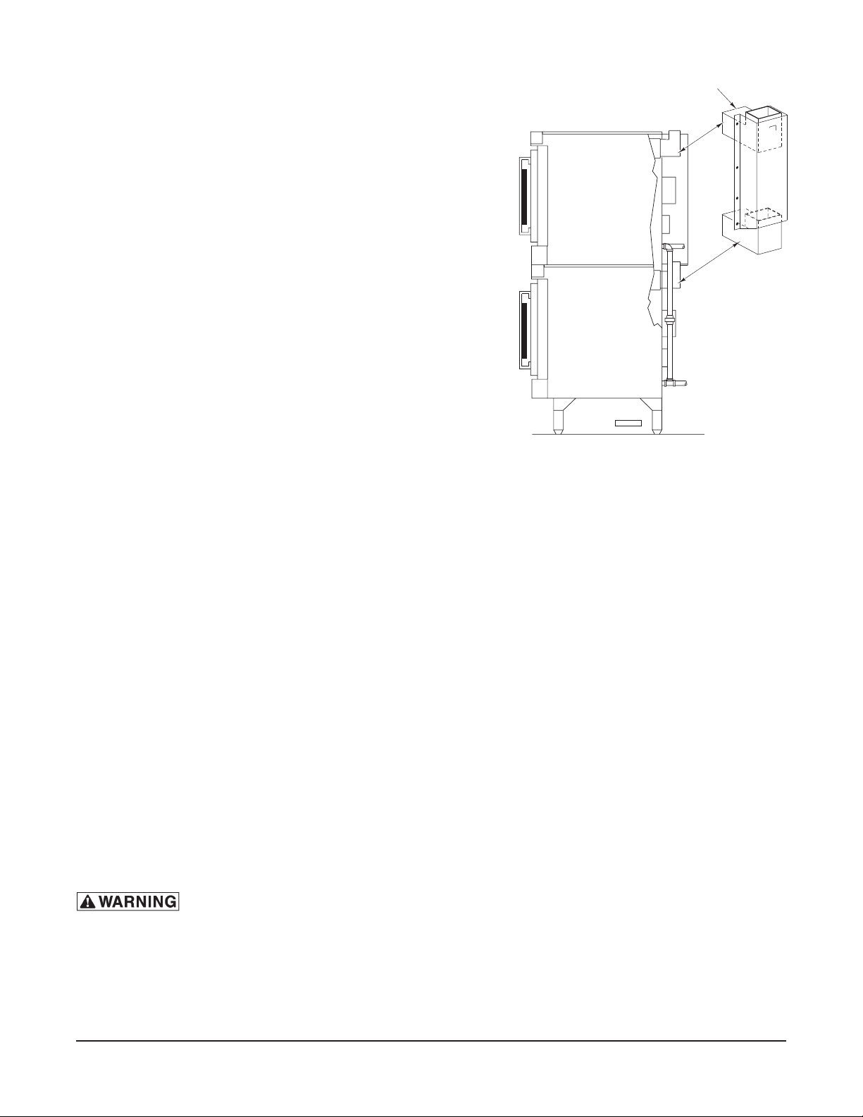
ASSEMBLING STACKED OVENS (OPTIONAL)
Unpack the ovens and stack kit. Position the oven to be
used as the bottom oven on its back for access to the
oven bottom, taking care not to scratch or damage it. The
gas pipe protrudes beyond the back; provide for this
when the oven is tipped back by resting it on suitable
spacers (2 x 4's, etc.). Attach the four leg assemblies with
the 24 bolts and lockwashers (six per leg).
Place the lower oven (with legs) on the floor and remove
7
two
/16 inch (11 mm) diameter knockouts on each side of
the top cover. Remove vent guard and discard it.
Move the oven with legs to the installed position and place
upper oven on top of lower oven using the locating studs.
Install the stacking flue (Fig. 3) with the four screws
provided.
STACKING FLUE
Connect the piping between the top oven and bottom
oven. For all gas supply connections, pipe joint compound
PL-53564
must be resistant to the action of propane gases.
Fig. 3
LEVELING
Make sure that the oven racks are level in the final installed position. If the oven is installed on legs,
turn the adjustable feet in or out to level the oven front-to-back and side-to-side. If the oven is installed
on casters, loosen set screws and turn casters in or out to level the oven front-to-back and side-to-side.
Retighten set screws after leveling.
GAS CONNECTION
Gas supply connections and any pipe joint compound must be resistant to the action of propane gases.
Location of the gas inlet is at the rear of the oven. Codes require that a gas shutoff valve must be
installed in the gas line ahead of the oven.
Connect gas supply after leveling the oven. The gas supply line must be at least the equivalent of
3
/4 inch (19 mm) iron pipe. Make sure the pipes are clean and free of obstructions, dirt or pipe joint
compound.
The ovens are equipped with fixed burner orifices which coincide with installation elevation.
The oven is provided with a regulator integral to the gas solenoid valve and requires no external
regulator.
Natural gas pressure regulators are preset for 3.5 inches W.C. (Water Column) (0.9 kPa); propane gas
pressure regulators are preset for 10 inches W.C. (2.5 kPa).
Prior to lighting, check all joints in the gas supply for leaks. Use soap and
water solution. Do not use an open flame.
A. Check all joints prior to the gas valve (solenoid) before lighting unit.
B. Check all joints beyond gas valve (solenoid) after unit is lit.
After piping has been checked for leaks, all piping receiving gas should be fully purged to remove air.
– 6 –
Page 7

TESTING THE GAS SUPPLY SYSTEM
1
When gas supply pressure exceeds
/2 psig (3.45 kPa), the oven and its individual shutoff valve must
be disconnected from the gas supply piping system.
1
When gas supply pressure is
/2 psig (3.45 kPa) or less, the oven should be isolated from the gas supply
system by closing its individual manual shutoff valve.
BURNER AIR ADJUSTMENT
Although main burner air is adjusted before shipment, it should be checked at the time of installation.
Excessive air will cause flames to lift off a burner when cold or may cause flash-back during normal
cycling of oven, particularly when propane gas is used.
Insufficient air will cause flames to burn with a yellow tip and result in carbon accumulation in the flame
chamber and heat exchanger tubes.
Contact your local Wolf Range servicer if required.
VENT SYSTEM
DO NOT obstruct the flow of flue gases from the flue located on the rear of the oven. It is recommended
that the flue gases be ventilated to the outside of the building through a ventilation system installed by
qualified personnel.
Ovens may use an optional down draft diverter flue method. This optional down draft diverter must be
purchased from the oven manufacturer and vented to the outside; otherwise, the installation of any such
device will void all oven certifications and warranties. When the diverter is supplied, it may be
connected to a Type “B” vent.
From the termination of the flue to the filters of the hood venting system, a minimum clearance of
18 inches (457 mm) should be maintained.
Information on the construction and installation of ventilating hoods may be obtained from
Removal from Cooking Equipment
, NFPA Standard No. 96 (latest edition), available from the National
Vapor
Fire Protection Association, Batterymarch Park, Quincy, MA 02269.
– 7 –
Page 8
ELECTRICAL CONNECTIONS
Electrical and grounding connections must comply with the applicable
portions of the National Electrical Code and/or other local electrical codes.
Appliances equipped with a flexible electric supply cord are provided with
a three-prong grounding plug. It is imperative that this plug be connected into a properly
grounded three-prong receptacle. If the receptacle is not the proper grounding type,
contact an electrician. Do not remove the grounding prong from this plug.
WKG series ovens with 120 V/60 Hz/1 PH electrical specification are equipped with a cord and plug
as standard equipment.
A wiring diagram is located on the inside of the control housing.
ELECTRICAL DATA
Minimum Circuit Ampacity
Model V/Hz/PH Maximum Protective Device
AMPS
120/60/1 15
208/60/1 (Opt.) 15
240/60/1 (Opt.) 15
WKGD 240/50/1 (Opt.) 15
220/380 (3W)/50/3 (Opt.) 15
220/380 (4W)/50/3 (Opt.) 15
240/415 (4W)/50/3 (Opt.) 15
Compiled in accordance with the National Electrical Code, NFPA-70 (latest edition).
– 8 –
Page 9
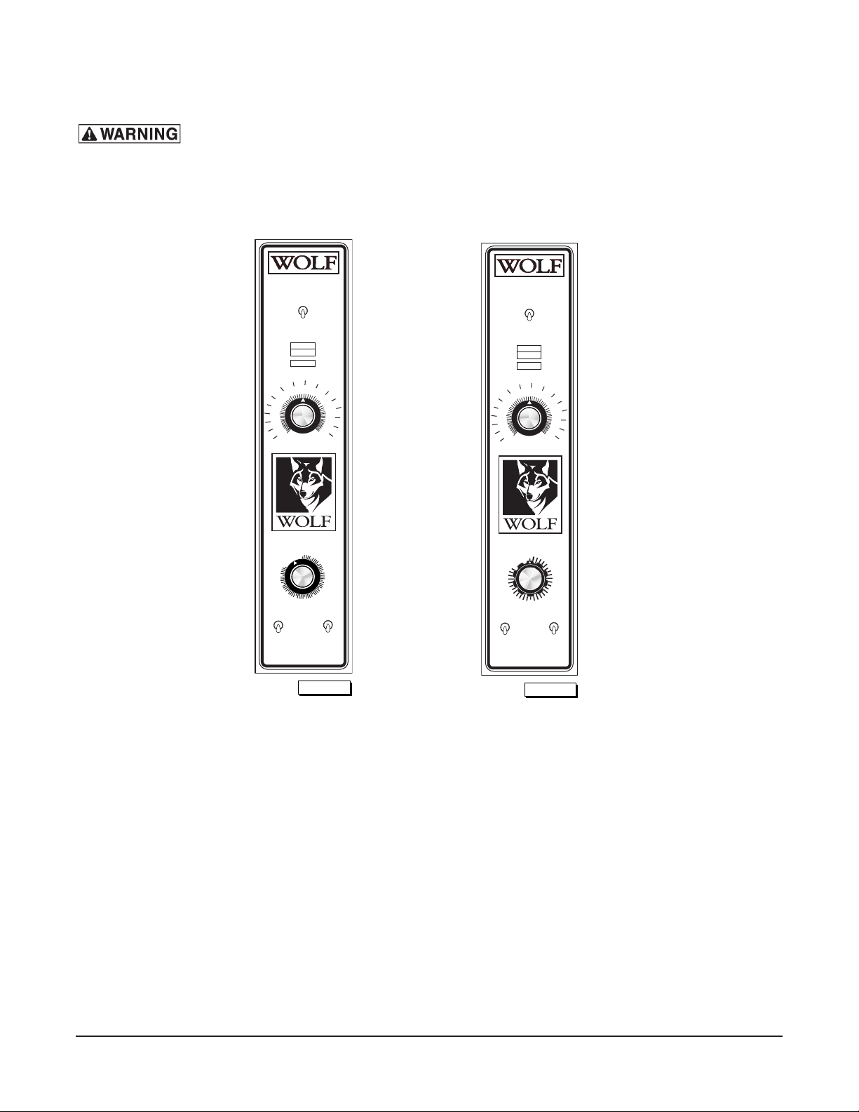
OPERATION
The oven and its parts are hot. Use care when operating, cleaning or
servicing the oven.
CONTROLS (Model WKGD Without Roast & Hold)
MASTER SWITCH
ON
OVEN COOL
ON
HEAT
IGNITION
THERMOSTAT
350
325
150
300
275
250
225
F
150
C
100
TEMPERATURE
TIMER
OFF
0
OFF
0
60
55
50
45
40
35
FAN SPEED
HI
LO
LO
PL-53558
OFF
375
5
30
LIGHTS
500
10
OFF
MASTER SWITCH
ON
OFF
OVEN COOL
ON
HEAT
IGNITION
200
400
425
450
475
250
15
20
25
ON
325
150
300
275
250
225
F
150
C
100
TEMPERATURE
5
4
FAN SPEED
HI
LO
LO
OFF
350
TIMER
OFF
0
3
375
500
LIGHTS
ON
OFF
200
400
425
450
475
250
1
2
PL-53557
Master Switch ON — Turns oven control circuits on.
OFF — Turns oven control circuits off.
OVEN COOL — Allows the fan motor to run with the doors ajar to speed oven cooling.
On Light (Amber) — Lit when Master Switch is ON.
Heat Light (White) — Comes on and goes off when the burner cycles on and off.
Ignition Light (Red) — Comes on if burner fails to ignite. When lighting the oven, the IGNITION
light flashes.
Thermostat — Controls oven temperature during cooking operation.
Timer (1 Hr. or 5 Hr.) — Sets the Bake time. Buzzer sounds continuously after timer counts down
to 0. Oven does not turn off. Turn Timer to OFF to stop buzzer. When oven
is not in use, keep Timer at OFF position.
Fan Speed Switch — Allows you to select HI or LO fan speed.
Lights Switch — Turns the lights in the oven ON or OFF.
– 9 –
Page 10
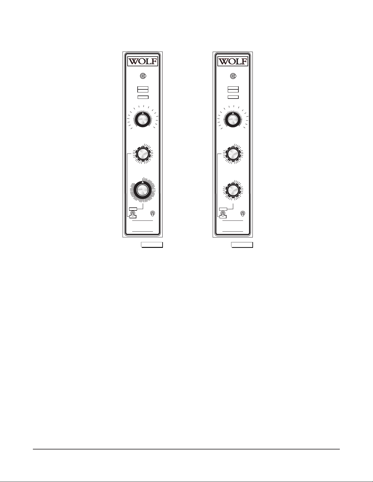
CONTROLS (Model WKGD With Roast & Hold)
MASTER SWITCH
ON
OFF
OVEN COOL
ON
HEAT
IGNITION
200
350
375
325
150
300
275
250
225
C
100
60
55
50
45
NORMAL
R & H
LIGHTING INSTRUCTIONS
PUSH MASTER SWITCH "ON"
IF BURNER FAILS TO LIGHT
WAIT 5 MINUTES FOR RETRIAL
SHUTDOWN INSTRUCTIONS
TURN GAS AND MASTER SWITCH "OFF"
F
150
TEMPERATURE
OFF
0
5
4
3
R & H TIMER
TIMER
0
OFF
40
35
FUNCTION
TURN GAS "OFF"
TURN GAS "OFF"
400
475
500
1
2
5
10
25
30
LIGHTS
ON
OFF
MASTER SWITCH
ON
OFF
OVEN COOL
ON
HEAT
IGNITION
200
350
375
325
150
425
450
250
15
20
300
275
250
225
C
100
NORMAL
R & H
LIGHTING INSTRUCTIONS
PUSH MASTER SWITCH "ON"
IF BURNER FAILS TO LIGHT
WAIT 5 MINUTES FOR RETRIAL
SHUTDOWN INSTRUCTIONS
TURN GAS AND MASTER SWITCH "OFF"
F
150
TEMPERATURE
OFF
0
5
4
3
R & H TIMER
OFF
0
5
4
3
TIMER
FUNCTION
TURN GAS "OFF"
TURN GAS "OFF"
400
500
1
2
1
2
LIGHTS
ON
OFF
425
450
475
250
PL-53555
PL-53556
Master Switch ON — Turns oven control circuits on.
OFF — Turns oven control circuits off.
OVEN COOL — Allows the fan motor to run with the doors ajar to speed oven cooling.
On Light (Amber) — Lit when Master Switch is ON.
Heat Light (White) — Comes on and goes off when the burner cycles on and off.
Ignition Light (Red) — Comes on if burner fails to ignite. When lighting the oven, the IGNITION
light flashes.
Temperature — Controls oven temperature when Function switch is on NORMAL or during
the first stage of Roast & Hold.
R & H Timer — Sets the first stage cooking time in Roast & Hold.
Timer (1 Hr. or 5 Hr.) — Sets the bake time when Function switch is on NORMAL. Buzzer sounds
continuously after timer counts down to 0. Oven does not turn off at end
of cycle. Turn Timer to OFF to stop buzzer. When oven is not in use, keep
Timer at OFF position.
Function Switch — Allows you to select NORMAL or R & H (Roast & Hold).
Normal: Uses the regular timer and high fan speed.
R & H: Uses the R & H Timer for the first stage of roasting at the
thermostat setting, selects a hold temperature of 160°F (71°C) during
second stage roasting. Uses low fan speed when burners are on.
Lights Switch — Turns the lights in the oven ON or OFF.
– 10 –
Page 11

BEFORE FIRST USE
Before using the oven for the first time, it must be burned in to release any odors that might result from
heating the new surfaces in the oven.
1. Using a clean, damp cloth, wipe the inside of the oven including the racks.
2. Close the oven doors, push the Master Switch to ON, turn the Temperature to 300°F (149°C), and
allow the oven to cycle for 2 hours or until no odor is detected before pushing the Master Switch
to OFF.
LIGHTING THE WKG SERIES OVENS
1. Turn the main gas supply ON.
2. Push Master Switch to ON.
3. If the oven fails to light, push the Master Switch to OFF, wait 5 minutes for retrial.
SHUT DOWN INSTRUCTIONS
1. Push Master Switch to OFF.
USING THE WKG SERIES OVENS
Preheating
1. Select the proper rack arrangement for the product to be cooked. Refer to RACK
ARRANGEMENTS section in this manual.
2. Make sure the doors are closed.
3. Push the Master Switch to ON. The amber ON light will come on, indicating that power to the oven
is on.
4. Set the two-speed Fan Speed switch to desired setting (without Roast & Hold models).
5. Set Temperature as desired. The HEAT light will come on and remain on until the oven reaches
set temperature (approximately 10 to 15 minutes for settings from 300°F (149°C) to 400°F
(204°C)). Refer to SUGGESTED COOKING GUIDELINES for temperatures and times for various
products.
6. Prepare product and place in suitable pans. When the white HEAT light goes off, the oven has
reached the desired preheat temperature.
Cooking
1. Open the doors and load the product into the oven. Place pans in the center of the racks. Close
the doors.
2. Set the Timer. After the preset time lapses, turn the Timer to OFF to stop the alarm.
3. When product is done, open the doors and carefully remove cooked product from the oven. Care
should be taken when wiping up spills, as oven is still hot.
– 11 –
Page 12

Roast & Hold (When Equipped)
1. Turn the oven ON.
2. Set the oven Temperature to the desired setting.
3. Position the Function switch on R & H.
4. Set the R & H Timer to the desired time.
• The oven will roast the product for the time set on the R & H Timer at the temperature set by
the oven thermostat. After the time has elapsed on the R & H Timer, the oven control will
automatically switch to the hold temperature of 160°F (71°C). In hold mode, the oven will
maintain a temperature of 160°F (71°C) until the oven is turned OFF. The blower fan will run
at low speed while the burner is ON and the unit is operating in Roast & Hold.
5. To turn Roast & Hold off, flip the Function switch to the NORMAL position. The oven temperautre
will return to the cooking setting.
End of Day
1. Turn Temperature to lowest setting.
2. Push the Master Switch to OVEN COOL. Leave door ajar while the fan is on to cool the oven.
3. When oven has cooled sufficiently, push the Master Switch to OFF.
4. Turn the gas valve OFF and clean oven.
Extended Shutdown
Repeat Steps 1 through 3 of End of Day. Unplug oven and shut off manual gas valve.
CONSERVING ENERGY
• Turn off unused equipment.
• Adjust menu patterns and cooking/baking schedules for optimum equipment use.
• Reduce thermostat settings in slack periods since gas equipment heats up and recovers quickly.
• Preheat only to required cooking temperature for specific food — not higher.
• Do not open the oven door unless absolutely necessary.
• Keep area around the oven door clean and free of food particles.
• Any obstruction that prevents the door from closing completely will adversely affect oven
efficiency.
– 12 –
Page 13
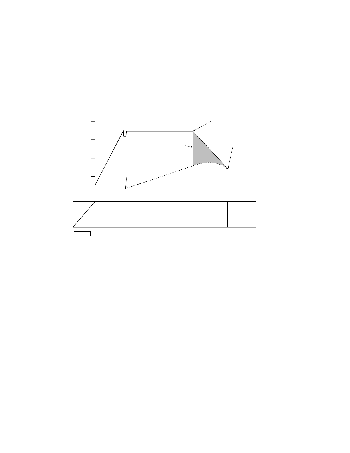
ROAST & HOLD OPERATION — (When Equipped)
Roast & Hold cooks the product in two stages. During first-stage cooking, the oven temperature is
regulated by the temperature setpoint and the R & H Time setting. After the time counts down to 00:00,
second-stage cooking begins. During second-stage cooking, the heating elements are off as the
temperature in the oven declines to the hold temperature. The doors should remain closed during
second-stage cooking.
When the hold temperature is reached, the display flashes HOLD. Temperature in the oven will be
maintained at the hold temperature until the oven is turned off.
ROAST AND HOLD DIAGRAM - Time vs. Temperature
400ºF
300ºF
200ºF
100ºF
TEMP.
TIME
PL-56291
OVEN TEMPERATURE
TIMER DISPLAY COUNTS DOWN.
COOKING FROM
STORED HEAT
LOAD PRODUCT
INTO OVEN
PRODUCT TEMPERATURE
PREHEAT FIRST-STAGE COOKING SECOND-STAGE
SHORT BEEP.
TIMER DISPLAYS "HOLD."
ROAST THERMOSTAT OFF.
HEATERS OFF UNTIL HOLD
TEMPERATURE IS REACHED.
COOKING
(DO NOT OPEN
DOORS)
HEATERS MAINTAIN
HOLD TEMPERATURE.
TIMER DISPLAY FLASHES
"HOLD."
HOLDING
PROPER UTENSILS
The use of proper utensils can enhance oven operation. Medium and lightweight pans allow the product
to warm faster. Roast meats in shallow pans deep enough to hold all juices yet allow free air circulation.
OPERATING HINTS
When using the convection oven for the first time with a particular food, check the degree of doneness
periodically before the suggested time has elapsed. This will ensure the desired doneness is achieved.
Record your temperature and time settings for various products. The convection oven can provide
consistent and repeatable results.
The convection oven is faster than conventional deck-type ovens; temperature settings are lower and
cook times are shorter. Since recipes and foods are subject to many variations and tastes, the
guidelines regarding Times and Temperatures in this manual are SUGGESTIONS ONLY. Experiment
with your food products to determine the cooking temperatures and times that give you the best results.
– 13 –
Page 14
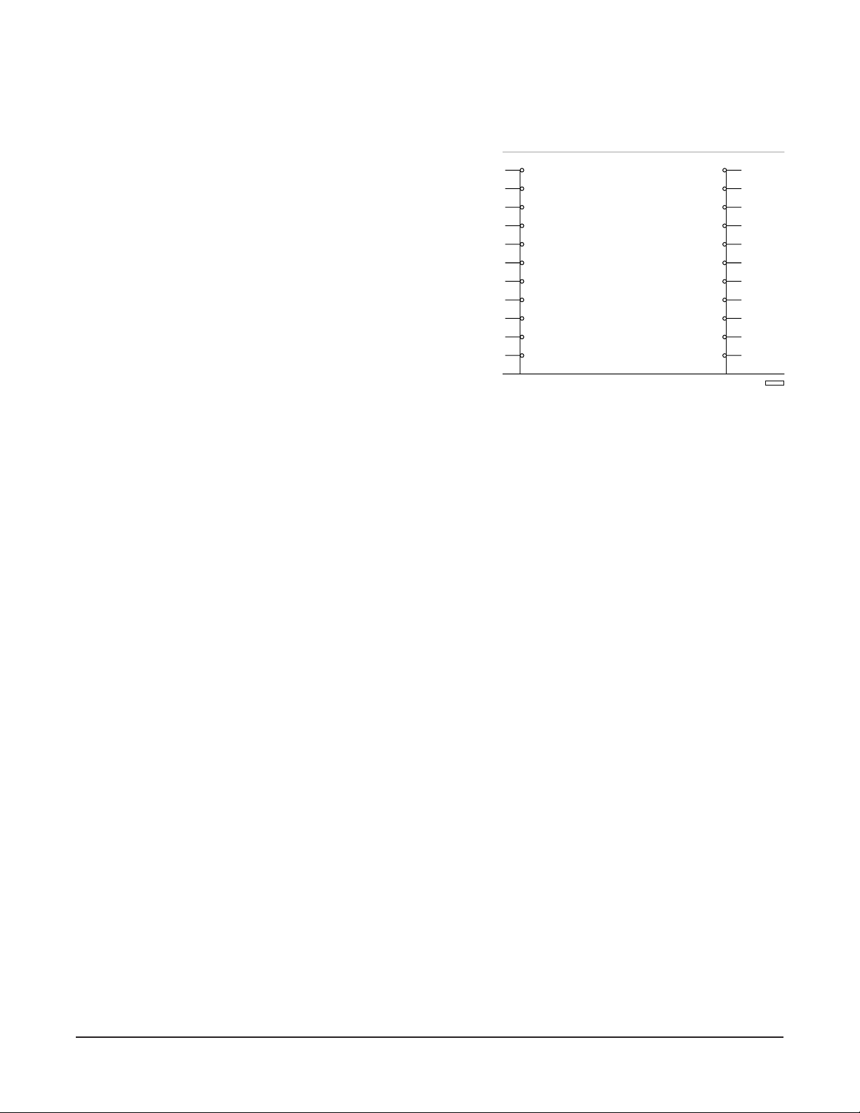
RACK ARRANGEMENTS
PL-52806
#1
RACK POSITION
#2
#3
#4
#5
#6
#7
#8
#9
#10
#11
All models are supplied with five racks and have a maximum operating capacity of six racks per oven.
The 11-position rack supports provide for maximum flexibility and proper rack spacing.
The following arrangements are recommended. The
position numbers are in numerical sequence starting at the
bottom (Fig. 4).
Arrangement #1 — Five racks in positions #2, #4, #6, #8
and #10 for cookies or reconstitution of frozen lunches at
maximum capacity. These are also the recommended
positions for general baking in sheet pans with products
not over 2
1
/2 inches (64 mm) high.
Arrangement #2 — Four racks in positions #1, #4, #7 and
#10 are for general baking in sheet pans, muffin pans, pie
or cake tins and pudding pans 3
1
/2 inches (89 mm) high with
products not over 4 inches (102 mm) high. This arrangement
can also be used for casseroles or meat dishes in #200
series food service pans 12 x 20 x 2
64 mm).
1
/2" (305 x 508 x
Fig. 4
Arrangement #3 — Three racks in positions #1, #5 and #9 are for baking breads or cakes in loaf or tube
pans and high meringue pies. This arrangement can also be used for casseroles, meat dishes or
cooking in pans up to 5
1
/
2 inches (140 mm) deep with products up to 6 inches (152 mm) high.
Arrangement #4 — Two racks in positions #1 and #6 are for cooking turkeys and other roasts up to
7 inches (178 mm) high.
With the rack in position #1, there is limited space for a water pan (see cooking chart in this manual).
When mixed loads or partial loading is regular practice, some users have developed other rack
arrangements to suit their particular needs.
SPECIAL PROCEDURES FOR BAKING
Yeast Bread: Cooking starts immediately in the convection oven. Yeast breads do not usually rise as
much in a convection oven as in a conventional oven. Therefore it is usually necessary to allow fuller
proof, 2
1
/2 to 3 times increase in volume, for best results.
Pies: When baking pies in your convection oven, three or four pies should be put on an 18 x 26" sheet
or bun pan. This procedure helps the bottom crust to bake, makes handling easier and reduces the
possibility of boilover spoiling the appearance of the pies on the lower racks.
HIGH LIMIT SWITCH
All ovens are equipped with a high limit switch, which senses the temperature of the oven to prevent
overheating. The high limit switch operates independently and will automatically shut the oven down
should the primary control fail. If this situation occurs, DO NOT attempt to bypass the high limit. Shut
the oven down and contact your local Wolf Range authorized service agency.
– 14 –
Page 15
RECOMMENDED TEMPERATURES AND TIMES FOR ROASTING
Meat roasting is most satisfactory at temperatures of 225 to 325°F (107 to 163°C) for beef, lamb, poultry
and ham; 325°F (163°C) for fresh pork as recommended by USDA and American Meat Institute.
A pan, approximately 12 x 20 x 1" (305 x 508 x 25 mm) full of water, may be placed in the oven bottom.
This water supplies humidity to reduce shrinkage. Water should be added if necessary during roasting.
Roasting pans should be no deeper than necessary to hold drippings (usually 2 to 2
1
/2" (51 to 64 mm)).
Cooking time and shrinkage may vary with roasting temperature, cut, grade of meat and degree of
doneness. Smaller cuts will generally show greater time savings than larger cuts at a given
temperature.
ROASTING TEMPERATURE CHART
TEMP
PRODUCT °F (°C) APPROXIMATE TIMES
Standing Rib Roast — Oven Ready 250 (121) 3 to 4 Hrs. — Rare
Rolled Rib Roasts — 20 to 22 lb (9.1 to 10 kg) 275 (135) 4 Hrs. — Med.
Veal Roast — 15 lb (6.8 kg) 300 (149) 3 Hrs. — Med. Well
Turkeys — 15 to 20 lb (6.8 to 9.1 kg) 300 (149) 3 Hrs.
Meat Loaf — 8 to 10 lb (3.6 to 4.5 kg) 350 (177) 45 to 60 Minutes
1
4 to 4
/2 Hrs. — Med.
COOKING HINTS
Forced air convection cooking is faster than conventional oven cooking, and therefore overcooking is
more common. Do not cook products faster than is practical for the best results. Since forced air
convection supplies heat to the surface of the product, the thicker or more massive a product is for its
type, the longer it will take to absorb enough heat to cook.
The oven will cook or bake full or partial loads at standard recipe temperatures. As with any oven, you
may wish to use a temperature of up to 25°F (-4°C) higher or lower than the recipe for the particular
product result that you prefer.
Once established, convection oven time and temperature settings should be noted on your recipe.
SUGGESTED COOKING GUIDELINES
Recommended temperatures, times and number of racks are intended as a guide only. Adjustments
must be made to compensate for variations in recipes, ingredients, preparation and personal
preference in product appearance.
The oven does not require special recipes. Excellent results can be obtained from any good
commercial recipe with reduced cooking times.
– 15 –
Page 16

RECOMMENDED TEMPERATURES, TIMES AND NUMBER OF RACKS FOR BAKING
TEMPERATURE TIME IN NO. OF
PRODUCT °F (°C) MINUTES RACKS
Cakes
Sheet Cakes
18 x 26 x 1" (457 x 660 x 25 mm) pan
Scaled 4
Scaled 6 to 71/2 lb (2.7 to 3.4 kg)/pan
Sheet Cakes
18 x 26 x 2" (457 x 660 x 51 mm) pan 300-325 (149-163) 25 to 35 4
Scaled 10 to 12 lb (4.5 to 5.4 kg)/pan 300-325 (149-163) 25 to 35 3
Or, two 12 x 18 x 2" (305 x 457 x 51 mm) pans
Scaled 5 to 6 lb (2.3 to 2.7 kg)/pan.
Angel or Sponge Cakes
Sheet Pans 18 x 26 x 1" (457 x 660 x 25 mm)
Scaled 5 to 6 lb (2.3 to 2.7 kg)/pan
Loaf or Tube Pans 315-340 (157-171) 20 to 30 3 – 4
Cupcakes 350-400 (177-204) 6 to 12 4
Frozen Fruit Pies 350-375 (177-191) 30 to 45 3 – 4
Pumpkin or Custard Pies 300-350 (149-177) 30 to 45 3 – 4
Cobblers
12 x 18 x 2" (305 x 457 x 51 mm) or
12 x 20 x 21/2" (305 x 508 x 64 mm)
Meringue Pies 350-425 (177-218) 6 to 10 2 – 4
Fruit Turnovers
18 x 26 x 1" (457 x 660 x 25 mm) pans 350-375 (177-191) 15 to 25 3 – 5
NOTE: Pies and cobblers; fruit, custard,
and pumpkin pies in pie pans should be
placed on 18 x 26 x 1" (457 x 660 x 25 mm)
pans for baking.
Cookies
Rolled or Pressed 350-400 (177-204) 6 to 12 3 – 5
Drop 350-400 (177-204) 6 to 15 3 – 5
Brownies 350 (177) 12 to 20 4 – 5
Yeast Breads NOTE: Yeast breads should
be fully proofed for best results.
Rolls — 1 oz 350-400 (177-204) 5 to 10 3 – 4
1
1
/2 to 21/2 oz 350-400 (177-204) 8 to 15 3 – 4
Loaf Bread — 1 lb (453.4 g) 325-375 (163-191) 20 to 40 3(30) Pans
Sweet Rolls & Danish Pastry 325-375 (163-191) 5 to 15 3 – 4
Biscuits — Rolled
Muffins 325-375 (163-191) 6 to 18 3 – 4
18 x 26 x 1" (457 x 660 x 25 mm) pan, 335-400 (168-204) 10 to 20 4
18 x 26 x 2" (457 x 660 x 51 mm) pan, 335-400 (168-204) 15 to 25 4
Corn Muffins 335-385 (168-196) 10 to 20 3 – 4
1
/2 to 6 lb (2 to 2.7 kg)/pan 325-360 (163-182) 20 to 23 5
335-350 (168-177) 22 to 25 4
300-325 (149-163) 15 to 20 4
350-400 (177-204) 30 to 45 3 – 4
1
/2" (13 mm) Thick 350-400 (177-204) 5 to 15 3 – 4
5 to 7 lb (2.3 to 3.2 kg)/pan
8 to 20 lb (3.6 to 9 kg)/pan
2(20) Pans
– 16 –
Page 17

REHEATING PREPARED FOODS
TEMPERATURE TIME IN NO. OF
PRODUCT °F (°C) MINUTES RACKS
Frozen French Fries 400-450 (204-232) 6 to 8 4
2 to 3
Frozen TV Dinners 350-400 (177-204) 10 to 12 2 – 5
Frozen Entrees 300-350 (149-177) 10 to 20 2 – 5
3
/4 to 1" (19 to 25 mm) Thick
Frozen Meals, 8 oz Foil Pkg. 350-400 (177-204) 20 to 30 2 – 5
Fish Sticks & Portions
Frozen Breaded, 1 oz 350-400 (177-204) 6 to 10 2 – 4
1/
2
2
to 3 oz 350-375 (177-191) 8 to 15 2 – 4
Chicken Pieces
Broiled or Oven Fried
Lobsters — 1 to 1
Lobster Tails — Frozen
Hamburger Patties
1
2 to 2
/2 lb (0.9 to 1.1 kg)/bird 375-425 (191-218) 8 to 15 2 – 5
1
2
/2 to 3 lb (1.1 to 1.4 kg)/bird 350-400 (177-204) 15 to 25 2 – 4
1
/2 lb (0.45 to 0.7 kg) 400-450 (204-232) 8 to 14 2 – 4
1
/2 to 3/4 lb (0.2 to 0.3 kg) 350-400 (177-204) 10 to 15 2 – 4
8 per lb, Med. to Well Done 400-450 (204-232) 5 to 6 2 – 6
6 per lb 400-450 (204-232) 7 to 10 2 – 6
4 per lb 375-450 (191-232) 8 to 12 2 – 6
CASSEROLES
Food Service Pans
2 to 3" (51 to 76 mm) deep 325-375 (163-191) 15 to 25
3 to 4" (76 to 102 mm) deep 325-375 (163-191) 20 to 35 2 – 4
Ramekins or Foil Pans 350-400 (177-204) 5 to 6 4 – 5
Up to 1
1
/2" (38 mm) deep 2 – 4
Frozen 10 to 15
MISCELLANEOUS PRODUCTS
Baked Potatoes
120 count per 50 lb (22.7 kg) 400-450 (204-232) 20 to 25 2 – 5
100 count per 50 lb (22.7 kg) 400-450 (204-232) 25 to 40 2 – 5
80 count per 50 lb (22.7 kg) 400-425 (204-218) 30 to 45 2 – 5
Pizza — Frozen or With
Prebaked Crust 425-475 (218-246) 5 to 10 2 – 4
Grilled Cheese Sandwiches 400-425 (204-218) 8 to 10 2 – 4
– 17 –
Page 18

CLEANING
Disconnect the electrical power to the machine and follow lockout / tagout
procedures.
Allow the oven to cool before cleaning.
Heat Circulation Tube
The heat circulation tube, located in the back of the oven cavity, should never be blocked. The heat
circulation tube should be kept clean at all times for proper operation of the oven. Clean with standard
oven cleaner at least once a week. Be sure to thoroughly clean all cleansing solution off before using
the oven again. It is also recommended that the oven be run at 400°F (204°C) for 20 minutes before
using to burn off any cleaning solution that was not thoroughly rinsed from the heat circulation tube.
Daily
Exterior stainless steel oven panels should be cleaned with a damp cloth. Stubborn soil may be
removed with detergent. (DO NOT USE DAWN
®
.) Rinse thoroughly and wipe dry with a soft, clean
cloth.
Clean porcelain oven interior daily with soap or detergent and water. Rinse thoroughly and wipe dry with
a soft, clean cloth.
Nickel-plated racks and rack supports are dishwasher-safe and may be removed for cleaning.
For exterior burned-on foods and grease which resist simple soap and water cleaning, an abrasive
cleanser (scouring powder) mixed into a paste may be used. Apply with stainless steel wool or sponge,
always rubbing with the grain. This treatment is equally effective for heat tint (slightly darkened areas
caused by oxidation). Again, remember to rub in the direction of the polish lines. Rinse with clear water
and dry with a soft cloth.
Do not use scouring powder on the glass window; it will scratch and fog the glass.
After processing some foods at low temperatures, odors may linger in the oven. These odors may be
cleared by setting the temperature to 500°F (260°C) and allowing the oven to run unloaded for 30 to
45 minutes.
GUIDELINES FOR MAINTAINING STAINLESS STEEL SURFACES
There are three basic things that can break down the surface layer of stainless steel and allow corrosion
to develop: 1) Abrasion; 2) Deposits and water and 3) Chlorides.
Avoid abrasion from rubbing with steel pads, wire brushes or scrapers that can leave iron deposits on
stainless steel; instead, use plastic scouring pads or soft cloths. For stubborn stains, use products such
as Cameo, Talc or Zud First Impression. Always rub parallel to the polish lines or with the grain.
Hard water can leave deposits that promote rust on stainless steel. Treated water from softeners or
certain filters can eliminate these mineral deposits. Deposits from food must be properly removed by
cleaning. Use mild detergent and nonchloride cleaners. Rinse thoroughly. Wipe dry. If using chloride
-containing cleaners or sanitizers,
rinse repeatedly
to avoid stainless steel corrosion. Where
appropriate, apply a polish recommended for stainless steel (such as Benefit or Super Sheen) for extra
protection and lustre.
– 18 –
Page 19
MAINTENANCE
The oven and its parts are hot. Use care when operating, cleaning or
servicing the oven.
Disconnect the electrical power to the machine and follow lockout / tagout
procedures.
LUBRICATION
The fan motor comes with sealed bearings and requires no lubrication.
VENT
Periodically check the flue, when the oven is cool, to be sure it is free of obstructions.
REPLACING LAMPS
• Allow oven to cool.
• Remove all racks by pulling forward, lifting up and out.
• Unscrew glass dome from light body.
• Replace the bulb.
• Reassemble glass dome and racks.
– 19 –
Page 20
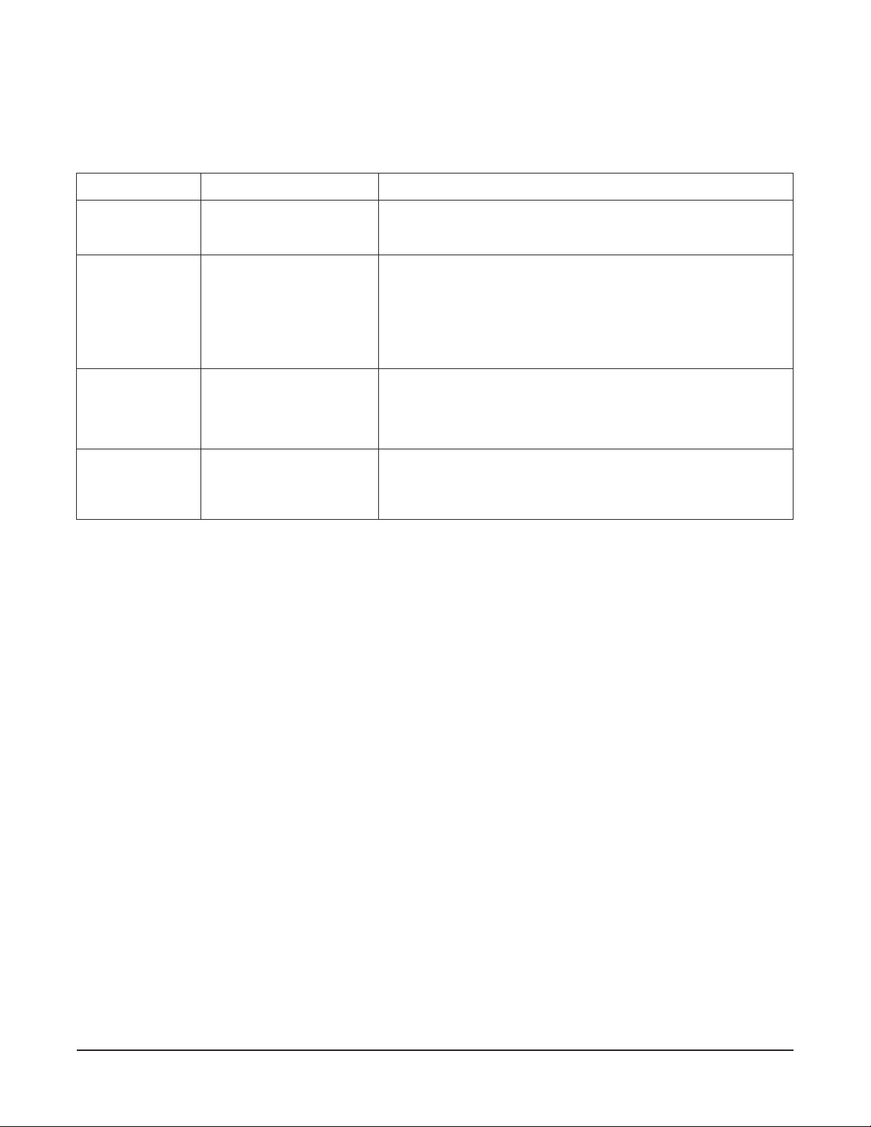
TROUBLESHOOTING
melborPesuaCelbissoPnoitcAevitcerroCdetsegguS
gninworbnevenU
.1
dekoocrevoro
.segde
ronapfoegde
.gnillips
.2
otgnilluptcudorP
.1
.tohootsinevO
.desuskcarynamooT
.leveltonsinevO
.1
.2
.1
.kcabottnorf
.noitalucricrettebwollaotskcarrewefesU
1
otleveldnaedisotedislevelebdluohs
/
8
.)senilediuGgnikooCotrefer(gnitteserutarepmetecudeR
kcarehT.kcabottnorfdnaedisotedis-skcarnevoleveL
morftnorfehttawol"
.2
evissecxE
.egaknirhs
thgilnoitingI
.slairt3retfa
.1
.nevoni
.2
eromroftilsniamer
sdnoces02naht
epmetgnitsaoR
.hgihoot
.ylppussagoN•
.deprawerasnapteehS
.2
wohsnapynafI.snapesoprup
.puorggnikabehtmorf
.1
retawniatniamoteruliaF
.)mc5.2x15x5.03(
erutar
.2
•
.erutarepmetecudeR
unim5rofffonevonruT
larenegmorfetarapesrettabgnikabrofdesusnappeeK
tievomer,prawotycnednetas
"1x02x21gnirusaemnevofomottobniretawfonapecalP
.thgilerotgnitpmettaerofebse
nepoerayehterusebotsevlavylppussagkcehC
SERVICE AND PARTS INFORMATION
To obtain service and parts information concerning this model, contact the Authorized Wolf Range
Service Agency in your area (refer to our website, www.wolfrange.com for a complete listing of
Authorized Service and Parts depots).
When calling for service, the following information must be available: model number, serial number,
manufacture date (MD) and voltage.
FORM 31133 Rev. E (Dec. 2007) PRINTED IN U.S.A.
– 20 –
 Loading...