

Wolf ICBCG304P/S/LP, ICBCG304T/S/LP, ICBCG304P/S, ICBCG365T/S, ICBCG365T/S/LP Installation Manual [en, fr, it, de, es]
...Page 1

GAS COOKTOPS
INSTALLATION GUIDE
GUÍA DE INSTALACIÓN
GUIDE D’INSTALLATION
GUIDA ALL’INSTALLAZIONE
INSTALLATIONSANLEITUNG
WF Intl GCooktops IG MultiLang 824551A 10-13.indd 1 2/19/14 12:08 PM
Page 2
2 | English
GAS COOKTOPS
Contents
2 Gas Cooktops
3 Specications
5 Installation
5 Troubleshooting
Features and specications are subject to change at any
time without notice. Visit wolfappliance.com/specs for the
most up-to-date information.
Product Information
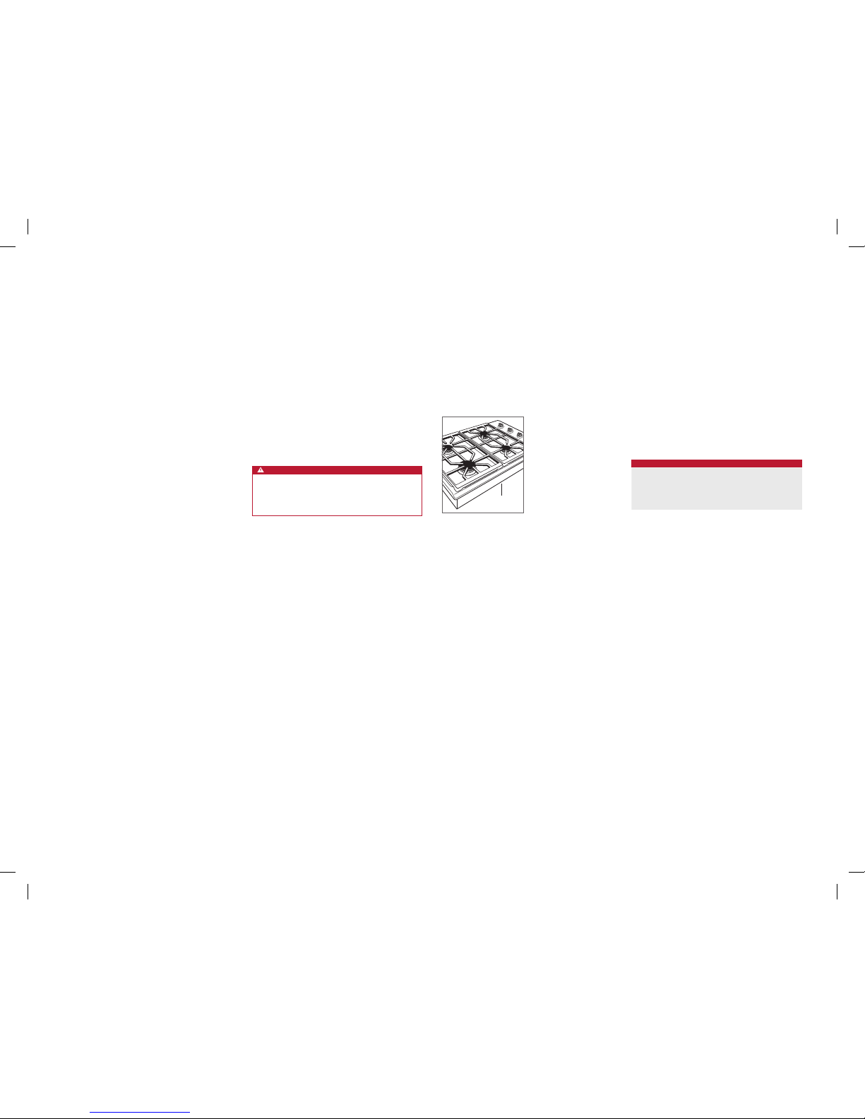
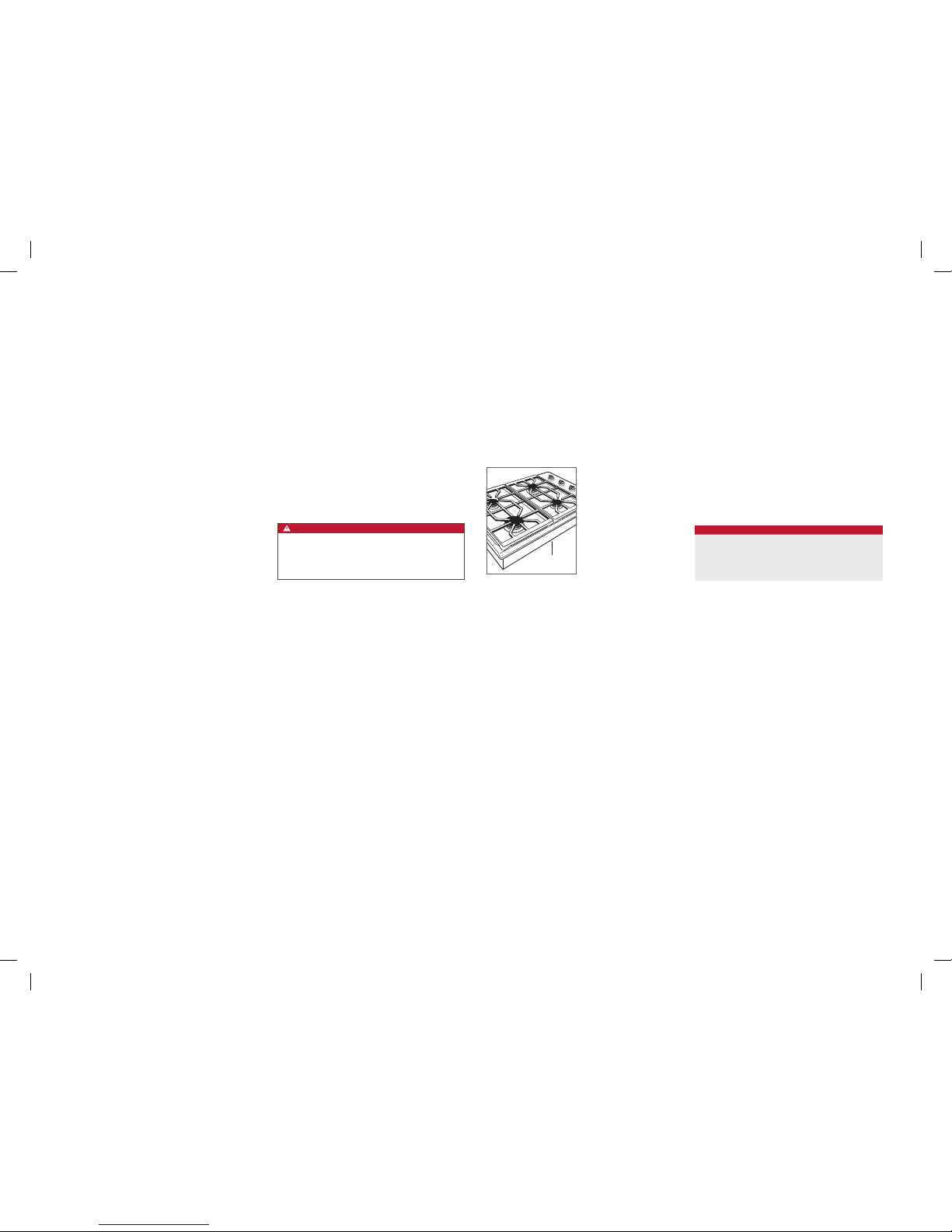
Important product information including the model and
serial number are listed on the product rating plate. The
rating plate is located on the bottom of the cooktop. Refer
to the illustration below.
If service is necessary, contact Wolf factory certied service
with the model and serial number.
Important Note
To ensure this product is installed and operated as safely
and efciently as possible, take note of the following types
of highlighted information throughout this guide:
IMPORTANT NOTE highlights information that is especially
important.
CAUTION indicates a situation where minor injury or product
damage may occur if instructions are not followed.
WARNING states a hazard that may cause serious injury or
death if precautions are not followed.
IMPORTANT NOTE: Save these instructions for the local
electrical inspector.
WARNING
This appliance shall be installed in accordance with the
regulations in force and only used in a well ventilated
space. Read the instructions before installing or using
this appliance.
Rating plate location.
RATING PLATE
Installation Requirements
If a cooktop is being installed above an oven, a minimum
of 6 mm is required between units. A minimum 140 mm is
required from the bottom of the cooktop to combustible
materials.
Electrical
Installation must comply with all applicable electrical codes.
Locate the electrical supply as shown in the illustrations
on page 4. A separate circuit, servicing only this appliance
is required. A ground fault circuit interrupter (GFCI) is not
recommended and may cause interruption of operation.
ELECTRICAL REQUIREMENTS
GAS COOKTOP
Electrical Supply grounded (earthed)
220-240 V AC, 50/60 Hz
Service 10 amp dedicated circuit
Receptacle grounding-type (earthed)
IMPORTANT NOTE: Connection of this appliance should be
through a fused connection unit or a suitable isolator, which
complies with national and local safety regulations. The
on/off switch should be easily accessible after the appliance has been installed. If the switch is not accessible after
installation (depending on country) an additional means of
disconnection must be provided for all poles of the power
supply. When switched off there must be an all pole contact
gap of 3 mm in the isolator switch. This 3 mm contact disconnect gap must apply to any isolator switch, fuses and/or
relays according to EN60335.
WF Intl GCooktops IG MultiLang 824551A 10-13.indd 2 2/19/14 12:08 PM
Page 3
wolfappliance.com | 3
SPECIFICATIONS
Gas Supply
Installation must conform with local codes and ordinances.
Locate the gas supply as shown in the illustrations on
page 4.
The cooktop is equipped for use with natural or liquid propane (LP) gas. The product rating plate has information on
the type of gas that should be used. For rating plate location, refer to the illustration below. If this information does
not agree with the type of gas available, check with the local
gas supplier.
Prior to installation, ensure that the local distribution conditions (nature of the gas and gas pressure) and the adjustment of the appliance are compatible. The adjustment
conditions for this appliance are stated on the label (or
rating plate). The data plate can be found on the underside
of the cooktop.
This appliance is not connected to a combustion products evacuation device. It shall be installed and connected
in accordance with current installation regulations. Particular attention shall be given to the relevant requirements
regarding ventilation.
GAS SUPPLY REQUIREMENTS
NATURAL GAS
Gas Supply Pressure 12.5 mb
Min Line Pressure 17.5 mb
Max Pressure to Regulator 100 mb
LP GAS
Gas Supply Pressure 25 mb
Min Line Pressure 27.4 mb
Max Pressure to Regulator 100 mb
GAS RATING
MODEL
TOTAL HEAT
OUTPUT
GAS
UNITS
APPLIANCE
CATEGORY
TYPES AND
PRESSURE (mbar) COUNTRY OF DESTINATION
ICBGC152T/S 6.2 kW
I2H G20 at 20
AT, BG, CR, CZ, DK, EE, FI, GR, HR, HU, IS, IE, IT, LV, LT,
NO, PT, RO, SK, SI, ES, SE, CH, TR, GB
I2E G20 at 20 DE, LU, PL
I2E+ G20 at 20/25 BE, FR
ICBCG152T/S/LP 1594 g/h I3P G31 at 37 FI, CR, GR, IE, HR, LU, NL, PL, SK, SI, ES, CH, TR, GB
ICBCG304T/S 14.2 kW
I2H G20 at 20
AT, BG, CR, CZ, DK, EE, FI, GR, HR, HU, IS, IE, IT, LV, LT,
NO, PT, RO, SK, SI, ES, SE, CH, TR, GB
I2E G20 at 20 DE, LU, PL
I2E+ G20 at 20/25 BE, FR
ICBCG304T/S/LP 3651 g/h I3P G31 at 37 FI, CR, GR, IE, HR, LU, NL, PL, SK, SI, ES, CH, TR, GB
ICBCG304P/S 14.2 kW
I2H G20 at 20
AT, BG, CR, CZ, DK, EE, FI, GR, HR, HU, IS, IE, IT, LV, LT,
NO, PT, RO, SK, SI, ES, SE, CH, TR, GB
I2E G20 at 20 DE, LU, PL
I2E+ G20 at 20/25 BE, FR
ICBCG304P/S/LP 3651 g/h I3P G31 at 37 FI, CR, GR, IE, HR, LU, NL, PL, SK, SI, ES, CH, TR, GB
ICBCG365T/S 16.9 kW
I2H G20 at 20
AT, BG, CR, CZ, DK, EE, FI, GR, HR, HU, IS, IE, IT, LV, LT,
NO, PT, RO, SK, SI, ES, SE, CH, TR, GB
I2E G20 at 20 DE, LU, PL
I2E+ G20 at 20/25 BE, FR
ICBCG365T/S/LP 4345 g/h I3P G31 at 37 FI, CR, GR, IE, HR, LU, NL, PL, SK, SI, ES, CH, TR, GB
ICBCG365P/S 16.9 kW
I2H G20 at 20
AT, BG, CR, CZ, DK, EE, FI, GR, HR, HU, IS, IE, IT, LV, LT,
NO, PT, RO, SK, SI, ES, SE, CH, TR, GB
I2E G20 at 20 DE, LU, PL
I2E+ G20 at 20/25 BE, FR
ICBCG365P/S/LP 4345 g/h I3P G31 at 37 FI, CR, GR, IE, HR, LU, NL, PL, SK, SI, ES, CH, TR, GB
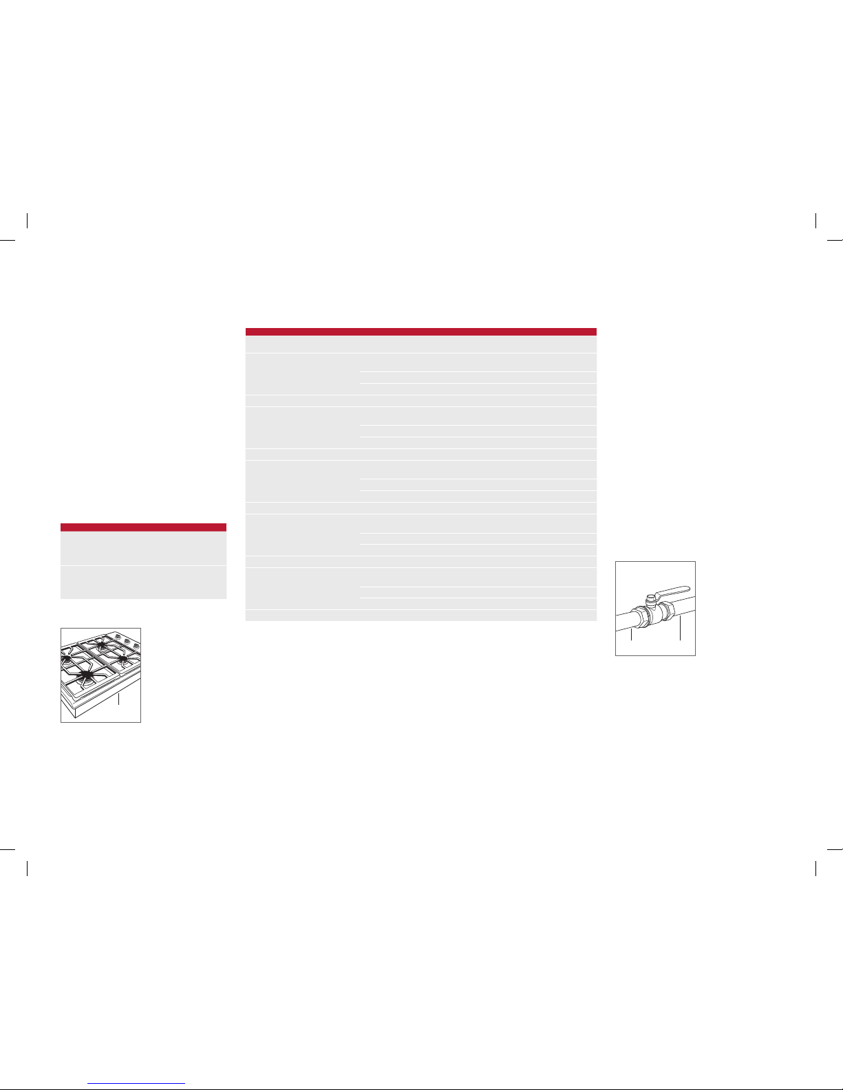
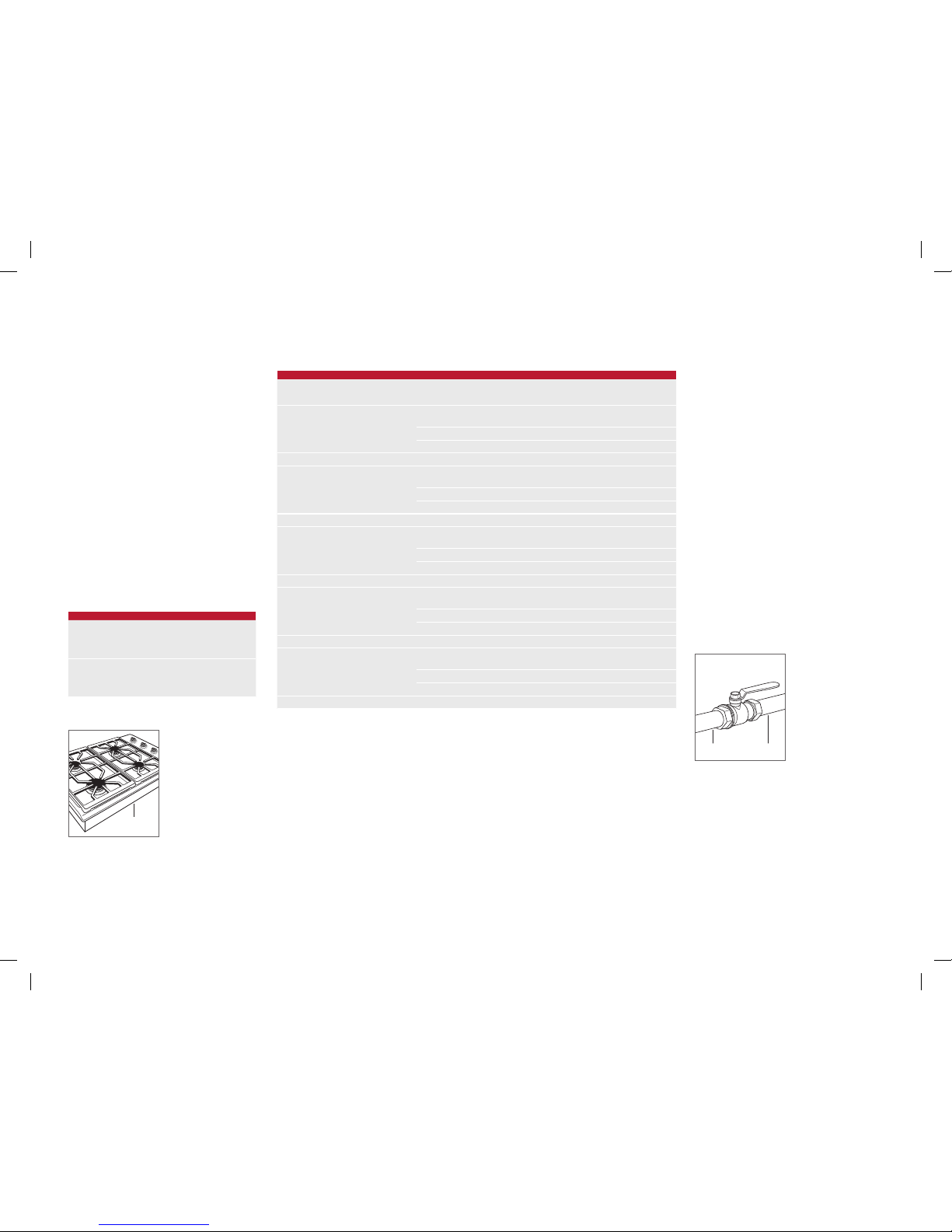
The cooktop must be connected to a regulated gas supply.
The supply line must be equipped with an approved external
gas shut-off valve located near the cooktop in an accessible
location. Do not block access to the shut-off valve. Refer to
the illustration below.
A gas supply line of 19 mm rigid pipe must be provided to
the cooktop. If local codes permit, a certied, .9 m long,
13 mm or 19 mm ID exible metal appliance connector is
recommended to connect the units 1/2" NPT (or ISO 7/1-14)
male inlet to the gas supply line. Pipe joint compounds, suitable for use with natural or LP gas should be used.
The appliance and its shut-off valve must be disconnected
from the gas supply piping system during any pressure
testing of the system at test pressures in excess of 100
mbar. The appliance must be isolated from the gas supply
piping system by closing its individual manual shut-off valve
during any pressure testing of the system at test pressures
equal to or less than 100 mbar.
Wolf natural gas cooktops will function up to 3124 m in
altitude without adjustment and LP gas cooktops will function up to 2621 m. If the installation exceeds these elevations, contact your authorized Wolf dealer for a high altitude
conversion kit.
SHUT-OFF VALVE
OPEN POSITION
GAS SUPPLYTO APPLIANCE
Gas shut-off valve.
Rating plate location.
RATING PLATE
WF Intl GCooktops IG MultiLang 824551A 10-13.indd 3 2/19/14 12:08 PM
Page 4
4 | English
SPECIFICATIONS
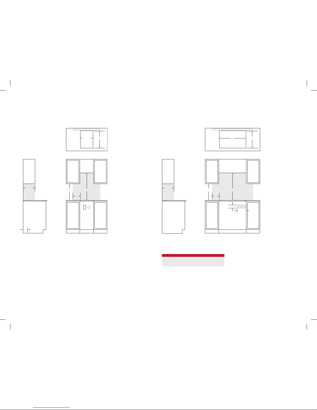
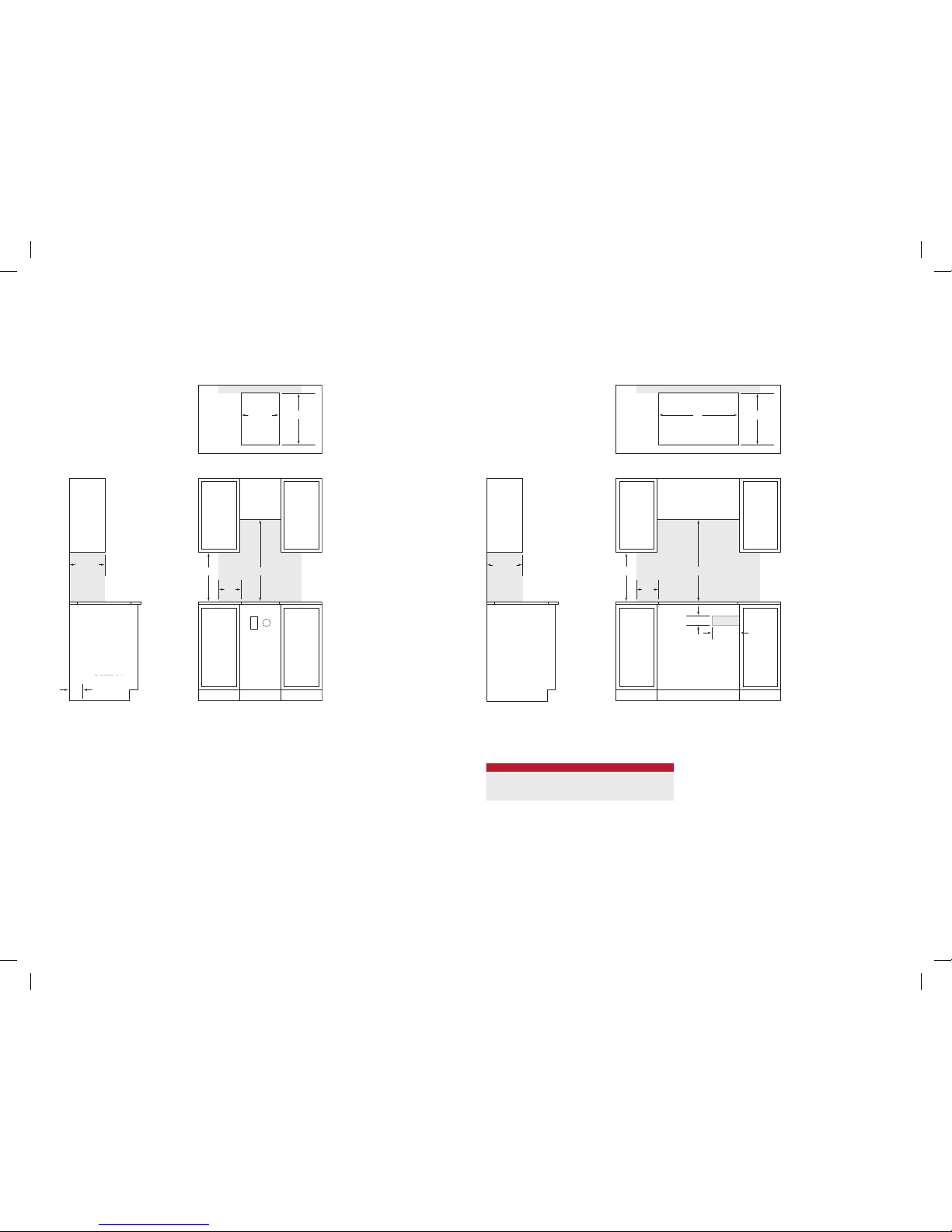
762 mm and 914 mm Gas Cooktop
STANDARD INSTALLATION
254 mm
102 mm
89 mm
FRONT VIEW
SIDE
VIEW
COUNTERTOP CUT-OUT
NO
TE: Shaded area above countertop indicates minimum clearance to combustible surfaces,
combus
tible materials cannot be located within this area.
El
ectrical and gas supply location only applies to installations with built-in oven.
762 mm
W
WIDTH
330 mm
457 mm
229
mm
495 mm
64 mm
64 mm
E G
CUT-OUT WIDTH
MODEL W
762 mm Cooktop 737 mm
914 mm Cooktop 889 mm
FRONT VIEWSIDE VIEW
COUNTERTOP CUT-OUT
NOTE: Shaded area above countertop indicates minimum clearance to combustible surfaces,
combustible materials cannot be located within this area.
330 mm
457 mm
178
mm
E G
127
mm
ELECTRICAL
AND GAS FLOOR
LOCATION
762 mm
356 mm
495 mm
64 mm
64 mm
381 mm Gas Cooktop
STANDARD INSTALLATION
WF Intl GCooktops IG MultiLang 824551A 10-13.indd 4 2/19/14 12:08 PM
Page 5
wolfappliance.com | 5
Wolf, Wolf & Design, Wolf Gourmet, W & Design and the color red as applied to knobs are registered trademarks and service marks of Wolf Appliance, Inc. Sub-Zero, Sub-Zero & Design, Dual Refrigeration, Constant Care, The Living Kitchen, Great American Kitchens The Fine Art of Kitchen Design, and Ingredients are registered trademarks and service marks of Sub-Zero,
Inc. (collectively, the “Company Marks.”) All other trademarks or registered trademarks are property of their respective owners in the United States and other countries.
Cooktop Installation
Remove cooktop and components from the shipping
package and recycle packing materials.
Lower the cooktop into the countertop cut-out. Center
cooktop in the opening with the front edge aligned parallel
to the front edge of the countertop. Using a pencil, outline
the rear edge of the cooktop on the countertop. Remove
cooktop.
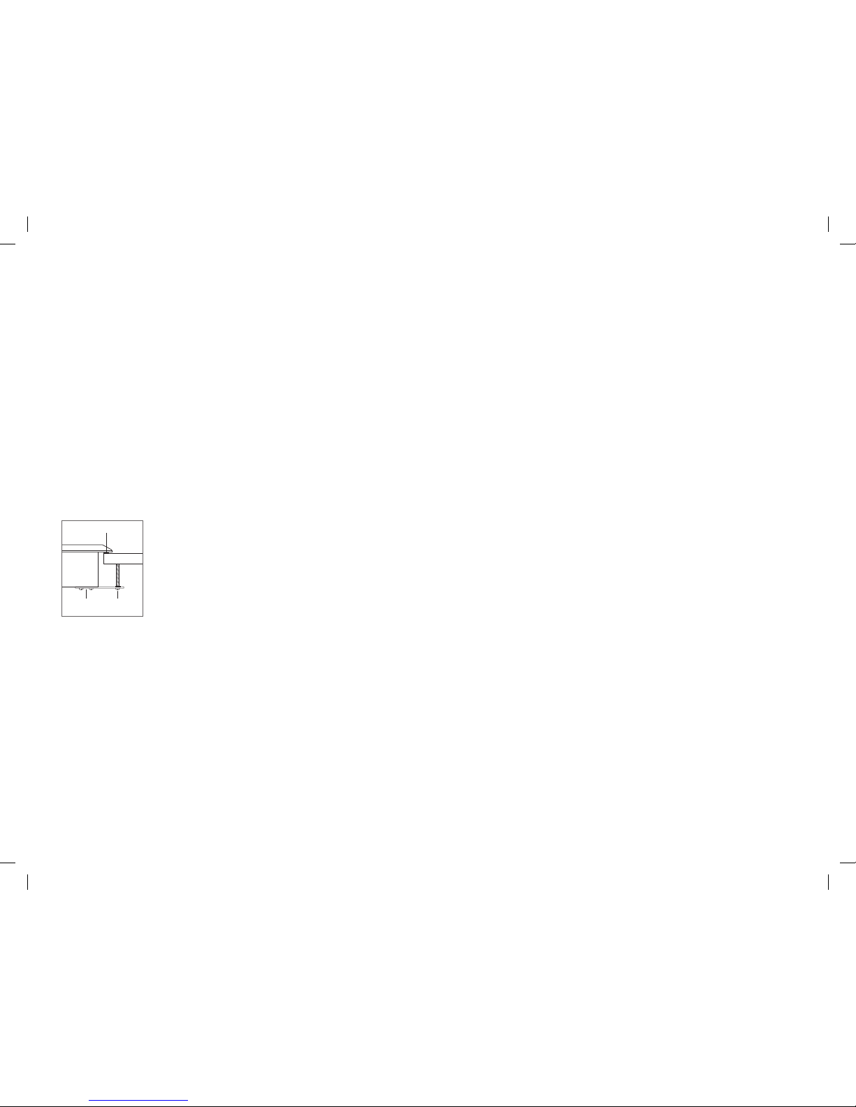
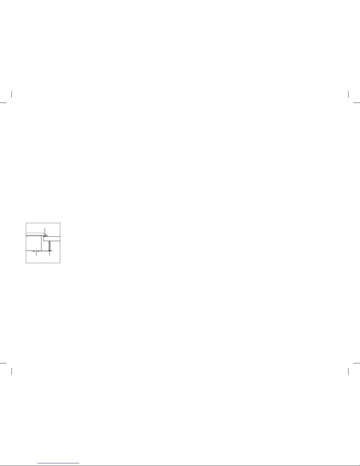
Apply the foam strip provided, to the perimeter of the countertop opening. Refer to the illustration below. Do not seal
the cooktop to the countertop.
Insert the cooktop into the opening. Verify the cooktop is
aligned with the front edge of the countertop.
Attach the brackets provided, to the bottom of the unit.
Insert the 89 mm clamping screws into the brackets. Use a
screwdriver to tighten clamping screws against the bottom
of the countertop. Do not overtighten screws. Refer to the
illustration below.
INSTALLATION
Gas Supply Connection
All connections to the gas piping must be wrench-tightened.
Do not overtighten or allow pipes to turn when tightening.
If a exible metal connector is being used, verify it is not
kinked, then attach the gas supply line to the regulator on
the cooktop. Open the valve and check for leaks by placing
a liquid detergent solution onto all gas connections. Bubbles
around connections indicate a gas leak. If a leak appears,
close the shut-off valve and adjust connections.
Troubleshooting
IMPORTANT NOTE: If the cooktop does not operate prop-
erly, follow these troubleshooting steps:
• Verify electrical power is supplied to the cooktop.
• Verify the gas supply shut-off valve is in the open
position.
• If the cooktop does not operate properly, contact Wolf
factory certied service. Do not attempt to repair the
cooktop. Wolf is not responsible for service required to
correct a faulty installation.
FOAM STRIP
COUNTERTOP
BRACKET
CLAMPING
SCREW
Cooktop installation.
WF Intl GCooktops IG MultiLang 824551A 10-13.indd 5 2/19/14 12:08 PM
Page 6
2 | Español
PLACAS DE GAS
Contenido
2 Placas de gas
3 Especicaciones
5 Instalación
5 Localización y solución de problemas
Las características y especicaciones están sujetas a cambios sin previo aviso. Visite wolfappliance.com/specs para
obtener la información más actualizada.
Información sobre el producto
En la placa de datos del producto encontrará información
importante, incluyendo el modelo y el número de serie. La
placa de datos está ubicada en la parte inferior del aparato.
Consulte la siguiente ilustración.
Si necesita ayuda, póngase en contacto con el servicio de
asistencia técnica autorizado de Wolf con el modelo y el
número de serie.
Nota importante:
Para garantizar que este producto se instala y funciona de
la forma más ecaz y segura posible, tenga en cuenta la
información que se destaca en esta guía:
Cuando aparece NOTA IMPORTANTE, se resalta información
que resulta especialmente importante.
PRECAUCIÓN indica una situación en la que se pueden
sufrir heridas leves o provocar daños al producto si no se
siguen las instrucciones.
AVISO indica el peligro de que se produzcan heridas graves
o incluso la muerte si no se respetan las precauciones.
NOTA IMPORTANTE: guarde estas instrucciones para el
inspector local.
AVISO
Este aparato debe instalarse de acuerdo con las normativas vigentes y solo puede ser utilizado en un lugar
que esté bien ventilado. Lea las instrucciones antes de
instalar o utilizar este aparato.
Ubicación de la placa de datos.
PLACA DE DATOS
Requisitos de instalación
Si la placa se va a instalar sobre un horno, es necesario
dejar un espacio mínimo de 6 mm entre las unidades.
Asimismo, es necesario dejar un mínimo de 140 mm de la
parte superior de la placa a los materiales combustibles.
Potencia
La instalación debe cumplir con toda la normativa local
aplicable en materia de electricidad.
Ubique la toma eléctrica tal como se muestra en las
ilustraciones de la página 4. Se necesita un circuito
independiente para esta unidad. No se recomienda utilizar
un interruptor de circuito de fallos de toma de tierra (GFCI),
ya que puede interrumpir el funcionamiento de la unidad.
REQUISITOS ELÉCTRICOS
PLACA DE GAS
Suministro eléctrico Conectado a tierra
220-240 V CA, 50/60 Hz
Servicio Circuito dedicado de 10 amperios
Enchufe Con toma de tierra
NOTA IMPORTANTE: la conexión de este aparato debe reali-
zarse a una unidad de conexión con fusibles o a un aislador
adecuado, que cumple con las normativas de seguridad
nacionales y locales. El interruptor de encendido/apagado
debe encontrarse en un lugar accesible después de haber
instalado el aparato. Si no es posible acceder al interruptor
después de la instalación (según el país), se deberá brindar
un medio de desconexión adicional para todos los polos
de la alimentación eléctrica. Al estar desconectado, deberá
existir una separación de contacto entre todos los polos
de 3 mm en el interruptor del aislador. Esta separación de
3 mm de desconexión de los contactos deberá aplicarse a
cualquier interruptor, fusibles o relés del aislador según la
norma EN60335.
WF Intl GCooktops IG MultiLang 824551A 10-13.indd 2 2/19/14 12:08 PM
Page 7
wolfappliance.com | 3
ESPECIFICACIONES
Suministro de gas
La instalación debe cumplir las ordenanzas y normativas
nacionales.
Ubique la toma de gas tal como se muestra en las ilustraciones de la página 4.
La placa de gas está equipada para usarse con gas natural
o gas propano líquido (GPL). Podrá encontrar información
sobre el tipo de gas que debería utilizar en la placa de datos
del producto. Consulte la siguiente ilustración para ver la
ubicación de la placa. Si esta información no coincide con
el tipo de gas que tiene disponible, póngase en contacto
con su proveedor de gas.
Antes de llevar a cabo la instalación, asegúrese de que las
condiciones de distribución locales (tipo y presión del gas)
y el ajuste del aparato son compatibles. Las condiciones
de ajuste de este aparato se especican en la etiqueta (o
en la placa de datos del producto). La placa de datos está
ubicada en la parte inferior del aparato.
Este aparato no está conectado a ningún dispositivo de
evacuación de productos de combustión. El aparato debe
instalarse y conectarse siguiendo las normativas de instalación vigentes. Debe prestar especial atención a los requisitos relevantes correspondientes a la ventilación.
REQUISITOS DEL SUMINISTRO DE GAS
GAS NATURAL
Presión del suministro de gas 12,5 mb
Presión mínima 17,5 mb
Presión máxima al regulador 100 mb
GAS LP
Presión del suministro de gas 25 mb
Presión mínima 27,4 mb
Presión máxima al regulador 100 mb
CLASIFICACIÓN DEL GAS
MODELO
PRODUCCIÓN
DE CALOR
TOTAL
UNIDADES
DE GAS
CATEGORÍA
DEL APARATO
TIPOS Y PRESIÓN
(mbar) PAÍS DE DESTINO
ICBGC152T/S 6,2 kW
I2H G20 a 20
AT, BG, CR, CZ, DK, EE, FI, GR, HR, HU, IS, IE, IT, LV,
LT, NO, PT, RO, SK, SI, ES, SE, CH, TR, GB
I2E G20 a 20 DE, LU, PL
I2E+ G20 a 20/25 BE, FR
ICBCG152T/S/LP 1594 g/h I3P G31 a 37 FI, CR, GR, IE, HR, LU, NL, PL, SK, SI, ES, CH, TR, GB
ICBCG304T/S 14,2 kW
I2H G20 a 20
AT, BG, CR, CZ, DK, EE, FI, GR, HR, HU, IS, IE, IT, LV,
LT, NO, PT, RO, SK, SI, ES, SE, CH, TR, GB
I2E G20 a 20 DE, LU, PL
I2E+ G20 a 20/25 BE, FR
ICBCG304T/S/LP 3651 g/h I3P G31 a 37 FI, CR, GR, IE, HR, LU, NL, PL, SK, SI, ES, CH, TR, GB
ICBCG304P/S 14,2 kW
I2H G20 a 20
AT, BG, CR, CZ, DK, EE, FI, GR, HR, HU, IS, IE, IT, LV,
LT, NO, PT, RO, SK, SI, ES, SE, CH, TR, GB
I2E G20 a 20 DE, LU, PL
I2E+ G20 a 20/25 BE, FR
ICBCG304P/S/LP 3651 g/h I3P G31 a 37 FI, CR, GR, IE, HR, LU, NL, PL, SK, SI, ES, CH, TR, GB
ICBCG365T/S 16,9 kW
I2H G20 a 20
AT, BG, CR, CZ, DK, EE, FI, GR, HR, HU, IS, IE, IT, LV,
LT, NO, PT, RO, SK, SI, ES, SE, CH, TR, GB
I2E G20 a 20 DE, LU, PL
I2E+ G20 a 20/25 BE, FR
ICBCG365T/S/LP 4345 g/h I3P G31 a 37 FI, CR, GR, IE, HR, LU, NL, PL, SK, SI, ES, CH, TR, GB
ICBCG365P/S 16,9 kW
I2H G20 a 20
AT, BG, CR, CZ, DK, EE, FI, GR, HR, HU, IS, IE, IT, LV,
LT, NO, PT, RO, SK, SI, ES, SE, CH, TR, GB
I2E G20 a 20 DE, LU, PL
I2E+ G20 a 20/25 BE, FR
ICBCG365P/S/LP 4345 g/h I3P G31 a 37 FI, CR, GR, IE, HR, LU, NL, PL, SK, SI, ES, CH, TR, GB
La placa debe conectarse a un suministro de gas regulado.
El suministro de gas debe estar equipado con una válvula
de cierre externa de gas homologada situada en un lugar
accesible, cerca de la placa. No obstruya el acceso a la
válvula de cierre. Consulte la siguiente ilustración.
Debe conectar la placa a un suministro de gas con una
tubería rígida de 19 mm. Si las normativas locales lo permiten, se recomienda utilizar un conector metálico exible
certicado de 0,9 mm y 13 mm o 19 mm de diámetro
interno para conectar la entrada macho 1/2" NPT (o ISO
7/1-14) de las unidades al suministro de gas. Debe utilizar
una pasta de recubrimiento para tuberías que sea adecuada
para que se pueda utilizar con gas LP o natural.
El aparato y su válvula de cierra deben estar desconectados del sistema de suministro de gas durante cualquier
prueba de la presión del sistema que supere los 100 mbar.
El aparato debe aislarse del sistema de suministro de gas
cerrando su válvula manual de cierre individual durante
cualquier prueba de la presión del sistema que sea igual o
inferior a 100 mbar.
Las placas de gas natural Wolf funcionarán en hasta 3124 m
de altitud sin necesidad de ajuste y las placas de gas LP, en
hasta 2621 m. Si la instalación supera estas cifras, póngase en contacto con su distribuidor Wolf autorizado para
obtener un kit de conversión para altitudes elevadas.
Ubicación de la placa de datos.
PLACA DE DATOS
SHUT-OFF VALVE
OPEN POSITION
GAS SUPPLYTO APPLIANCE
Válvula de cierre del gas.
SUMINISTRO
DE GAS
AL APARATO
POSICIÓN ABIERTA DE
LA VÁLVULA DE CIERRE
WF Intl GCooktops IG MultiLang 824551A 10-13.indd 3 2/19/14 12:08 PM
Page 8
4 | Español
ESPECIFICACIONES
Placa de gas de 762 mm y 914 mm
INSTALACIÓN ESTÁNDAR
254 mm
102 mm
89 mm
FRONT VIEW
SIDE
VIEW
COUNTERTOP CUT-OUT
NO
TE: Shaded area above countertop indicates minimum clearance to combustible surfaces,
combus
tible materials cannot be located within this area.
El
ectrical and gas supply location only applies to installations with built-in oven.
762 mm
W
WIDTH
330 mm
457 mm
229
mm
495 mm
64 mm
64 mm
E G
ANCHURA DEL CORTE
MODELO Anch.
Placa de 762 mm 737 mm
Placa de 914 mm 889 mm
FRONT VIEWSIDE VIEW
COUNTERTOP CUT-OUT
NOTE: Shaded area above countertop indicates minimum clearance to combustible surfaces,
combustible materials cannot be located within this area.
330 mm
457 mm
178
mm
E G
127
mm
ELECTRICAL
AND GAS FLOOR
LOCATION
762 mm
356 mm
495 mm
64 mm
64 mm
Placa de gas de 381 mm
INSTALACIÓN ESTÁNDAR
CORTE DE LA ENCIMERA
ANCHO
A
VISTA FRONTAL
VISTA LATERAL
CORTE DE LA ENCIMERA
VISTA FRONTALVISTA LATERAL
NOTA: el área sombreada sobre la encimera indica la distancia mínima a supercies combustibles, no puede
haber materiales combustibles en esta área
NOTA: el área sombreada sobre la encimera indica la distancia mínima a supercies combustibles, no puede
haber materiales combustibles en esta área.
La ubicación de la toma eléctrica y de gas solo se aplica a una instalación con horno empotrable.
UBICACIÓN DEL
SUELO ELÉCTRICO
Y DEL GAS
WF Intl GCooktops IG MultiLang 824551A 10-13.indd 4 2/19/14 12:08 PM
Page 9
wolfappliance.com | 5
Wolf, Wolf & Design, Wolf Gourmet, W & Design son marcas registradas y marcas de servicio de Wolf Appliance, Inc. Sub-Zero, Sub-Zero & Design, Dual Refrigeration, Constant Care, The Living Kitchen, Great American Kitchens The Fine Art of Kitchen Design, and Ingredients son marcas registradas y marcas de servicio de Sub-Zero, Inc., (en su conjunto, las «Marcas
de la Empresa»). Todas las demás marcas o marcas registradas son propiedad de sus respectivos propietarios en los Estados Unidos y en otros países.
Instalación de la placa
Desembale la placa y sus componentes y recicle los materiales del embalaje.
Inserte la placa en la encimera en la que la va a instalar.
Centre la placa en la cavidad con el borde delantero alineado en paralelo al borde delantero de la encimera. Con
un lápiz, delimite el borde trasero de la placa en la encimera. Retire la placa.
Aplique el embellecedor suministrado al perímetro de la
cavidad de la encimera. Consulte la siguiente ilustración.
No selle la placa a la encimera.
Coloque la placa en la cavidad de la encimera. Compruebe
que la placa está alineada con el borde delantero de la
encimera.
Fije los soportes suministrados, a la parte inferior de la
unidad. Inserte los tornillos de sujeción de 89 mm en los
soportes. Utilice un destornillador para apretar los tornillos
de sujeción a la parte inferior de la encimera. No apriete
demasiado los tornillos. Consulte la siguiente ilustración.
INSTALACIÓN
Conexión del suministro de gas
Todas las conexiones a los conductos de gas deberán
apretarse con una herramienta adecuada. No los apriete
demasiado ni permita que las tuberías se giren mientras los
aprieta.
Si utiliza un conector exible de metal, compruebe que no
esté torcido, y seguidamente conecte el tubo del suministro
de gas al regulador de la placa. Abra la válvula y compruebe
que no hay fugas colocando una solución de detergente
líquido en todas las conexiones de gas. Si aparecen burbujas alrededor de las conexiones, signica que hay una
fuga de gas. En ese caso, cierre la válvula de cierre y ajuste
las conexiones.
Localización y solución de problemas
NOTA IMPORTANTE: si la placa no funciona correctamente,
siga estos pasos de localización y solución de problemas:
• Compruebe que la placa está conectada a la red
eléctrica.
• Compruebe que la válvula de cierre del suministro de
gas está en posición abierta.
• Si la placa no funciona correctamente, póngase en
contacto con un servicio de asistencia técnica Wolf
autorizado. No intente realizar ninguna reparación en
la placa. Wolf no se hace responsable de las tareas de
mantenimiento que deban realizarse para corregir una
instalación defectuosa.
FOAM STRIP
COUNTERTOP
BRACKET
CLAMPING
SCREW
Instalación de la placa.
EMBELLECEDOR
SOPORTE TORNILLO DE
SUJECIÓN
ENCIMERA
WF Intl GCooktops IG MultiLang 824551A 10-13.indd 5 2/19/14 12:08 PM
Page 10
2 | Français
PLAQUES DE CUISSON À GAZ
Table des matières
2 Plaques de cuisson gaz
3 Spécications
5 Installation
5 Dépistage des pannes
Les caractéristiques et spécications peuvent être modiées
à tout moment sans préavis. Pour prendre connaissance
des informations les plus récentes, consultez notre site
Internet, wolfappliance.com/specs.
Information concernant le produit
Les renseignements importants concernant le produit,
notamment la référence modèle et le numéro de série,
gurent sur la plaque des caractéristiques du produit. La
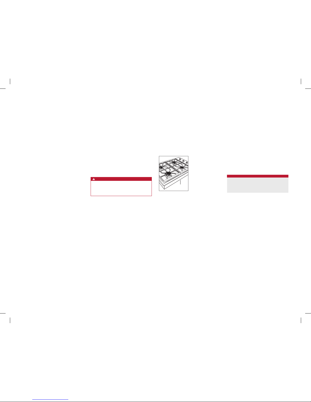
plaque des caractéristiques se trouve sur le dessous de la
plaque de cuisson. Reportez-vous à l'illustration ci-après.
Si vous devez contacter le service après-vente, contactez
le prestataire agréé par l'usine Wolf avec les numéros de
modèle et de série.
Remarque importante
Pour garantir une installation de ce produit aussi sûre et efcace que possible, veuillez faire particulièrement attention
aux mentions mises en évidence tout au long de ce guide,
notamment :
REMARQUE IMPORTANTE met l'accent sur un renseigne-
ment particulièrement important.
MISE EN GARDE signale un danger qui pourrait causer une
blessure mineure ou endommager le produit si vous ne
suivez pas les instructions.
AVERTISSEMENT signale un danger qui pourrait causer
des blessures graves voire fatales si vous ne prenez pas
certaines précautions.
REMARQUE IMPORTANTE : conservez ces instructions pour
l'électricien local chargé des inspections.
AVERTISSEMENT
Cet appareil ménager doit être installé conformément
aux règlements en vigueur et utilisé uniquement dans
un endroit bien ventilé. Lisez toutes les instructions
avant d'installer ou d'utiliser cet appareil.
Emplacement de la plaque des
caractéristiques.
PLAQUE DES
CARACTÉRISTIQUES
Exigences relatives à l’installation
Si une plaque de cuisson est installée au-dessus d'un four, il
faut au moins 6 mm entre les appareils. il faut conserver un
espace d'au moins 140 mm entre le dessous de la plaque
de cuisson et les matériaux combustibles.
Électricité
L'installation doit se conformer à tous les codes électriques
applicables.
Identiez l'alimentation électrique comme illustré sur les
illustrations de la page 4. Il est nécessaire d'avoir un circuit
indépendant, alimentant uniquement cet appareil ménager.
Il n'est pas recommandé d'avoir recours à un disjoncteur
différentiel (GFCI) qui pourrait provoquer l'interruption du
fonctionnement de l'appareil.
CONFIGURATION ÉLECTRIQUE
PLAQUE DE CUISSON GAZ
Alimentation électrique mise à la terre
220-240 V CA, 50/60 Hz
Service Circuit dédié de 10 A
Prise Type mise à la terre
REMARQUE IMPORTANTE : le branchement de cet appareil
ménager doit se faire par le biais d'une prise avec fusible
de protection ou un sectionneur adapté conformément à
la règlementation nationale et locale en matière de sécurité
électrique. On doit pouvoir accéder facilement à l'interrupteur une fois l'appareil ménager installé. Si ce n'est pas le
cas, il faudra, en fonction de la réglementation en vigueur
dans le pays, fournir un moyen supplémentaire de déconnecter tous les pôles de l'alimentation. Une fois déconnecté,
il doit y avoir une distance de 3 mm entre les contacts
des pôles dans le sectionneur. Cet écart de 3 mm entre
les contacts des pôles doit s'appliquer à tout sectionneur,
fusible ou relais conformément à la norme EN60335.
WF Intl GCooktops IG MultiLang 824551A 10-13.indd 2 2/19/14 12:08 PM
Page 11
wolfappliance.com | 3
SPÉCIFICATIONS
Alimentation en gaz
L'installation doit se conformer aux codes et aux règlements
locaux.
Identiez l'alimentation en gaz comme illustré sur les illustrations de la page 4.
La plaque de cuisson est adaptée pour pouvoir fonctionner
au gaz naturel ou au propane (LP). La plaque des caractéristiques du produit précise le type de gaz à utiliser. Pour
l'emplacement de la plaque des caractéristiques, reportezvous à l'illustration ci-après. S'il ne correspond pas au type
de gaz disponible, contactez votre fournisseur de gaz local.
Avant l'installation, assurez-vous que l'appareil ménager est
réglé conformément aux conditions de distribution locales
(nature et pression du gaz). Les conditions de réglage de cet
appareil ménager sont indiquées sur l'étiquette (ou plaque
des caractéristiques). La plaque des caractéristiques se
trouve sur le dessous de la plaque de cuisson.
Cet appareil n'est pas branché à un dispositif d'évacuation
de produits de combustion. L'appareil doit être installé et
branché conformément aux règlements d'installation actuellement en vigueur. Les exigences pertinentes relatives à la
ventilation doivent être rigoureusement observées.
CONFIGURATION DE L'ALIMENTATION EN GAZ
GAZ NATUREL
Pression de l'alimentation en gaz 12,5 mb
Pression minimale de la conduite 17,5 mb
Pression maximale vers le régulateur 100 mb
Propane (LP)
Pression de l'alimentation en gaz 25 mb
Pression minimale de la conduite 27,4 mb
Pression maximale vers le régulateur 100 mb
DÉBIT DU GAZ
MODÈLE
SORTIE DE
CHALEUR
TOTALE
UNITÉS
DE GAZ
CATÉGORIE
D'APPAREILS
MÉNAGERS
TYPES ET
PRESSIONS (mbar) PAYS DE DESTINATION
ICBGC152T/S 6,2 kW
I2H G20 à 20
AT, BG, CR, CZ, DK, EE, FI, GR, HR, HU, IS, IE, IT, LV, LT,
NO, PT, RO, SK, SI, ES, SE, CH, TR, GB
I2E G20 à 20 DE, LU, PL
I2E+ G20 à 20/25 BE, FR
ICBCG152T/S/LP 1 594 g/h I3P G31 à 37 FI, CR, GR, IE, HR, LU, NL, PL, SK, SI, ES, CH, TR, GB
ICBCG304T/S 14,2 kW
I2H G20 à 20
AT, BG, CR, CZ, DK, EE, FI, GR, HR, HU, IS, IE, IT, LV, LT,
NO, PT, RO, SK, SI, ES, SE, CH, TR, GB
I2E G20 à 20 DE, LU, PL
I2E+ G20 à 20/25 BE, FR
ICBCG304T/S/LP 3 651 g/h I3P G31 à 37 FI, CR, GR, IE, HR, LU, NL, PL, SK, SI, ES, CH, TR, GB
ICBCG304P/S 14,2 kW
I2H G20 à 20
AT, BG, CR, CZ, DK, EE, FI, GR, HR, HU, IS, IE, IT, LV, LT,
NO, PT, RO, SK, SI, ES, SE, CH, TR, GB
I2E G20 à 20 DE, LU, PL
I2E+ G20 à 20/25 BE, FR
ICBCG304P/S/LP 3 651 g/h I3P G31 à 37 FI, CR, GR, IE, HR, LU, NL, PL, SK, SI, ES, CH, TR, GB
ICBCG365T/S 16,9 kW
I2H G20 à 20
AT, BG, CR, CZ, DK, EE, FI, GR, HR, HU, IS, IE, IT, LV, LT,
NO, PT, RO, SK, SI, ES, SE, CH, TR, GB
I2E G20 à 20 DE, LU, PL
I2E+ G20 à 20/25 BE, FR
ICBCG365T/S/LP 4 345 g/h I3P G31 à 37 FI, CR, GR, IE, HR, LU, NL, PL, SK, SI, ES, CH, TR, GB
ICBCG365P/S 16,9 kW
I2H G20 à 20
AT, BG, CR, CZ, DK, EE, FI, GR, HR, HU, IS, IE, IT, LV, LT,
NO, PT, RO, SK, SI, ES, SE, CH, TR, GB
I2E G20 à 20 DE, LU, PL
I2E+ G20 à 20/25 BE, FR
ICBCG365P/S/LP 4 345 g/h I3P G31 à 37 FI, CR, GR, IE, HR, LU, NL, PL, SK, SI, ES, CH, TR, GB
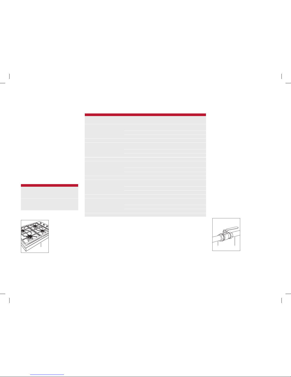
La plaque de cuisson doit être raccordée à une alimentation en gaz réglementaire. La conduite d'alimentation doit
être équipée d'un robinet d'arrêt du gaz extérieur agréé à
proximité de la cuisinière, dans un endroit accessible. Ne
bloquez pas l'accès au robinet. Reportez-vous à l'illustration
ci-après.
Une conduite rigide d'alimentation en gaz de 19 mm doit
être fournie à l'emplacement de la plaque de cuisson. Si
les codes locaux le permettent, l'utilisation d'un connecteur d'électroménager homologué métallique et souple de
0,9 m de long et de 13 mm ou 19 mm de diamètre interne
est recommandé pour raccorder la prise mâle 1/2 po NPT
(ou ISO 7/1-14) à la conduite d'alimentation en gaz. Il est
recommandé d'utiliser la pâte pour joints de tuyau adaptée
au gaz naturel ou propane.
L'appareil ménager et son robinet d'arrêt du gaz doivent
être déconnectés du système de conduites d'alimentation
en gaz lors des essais de pression du système lorsque les
pressions testées dépassent 100 mbar. L'appareil ménager
doit être isolé du système de conduites d'alimentation en
gaz en coupant son robinet d'arrêt manuel individuel lors
des essais de pression du système lorsque les pressions
testées sont égalent ou supérieures à 100 mbar.
Les plaques de cuisson Wolf gaz naturel fonctionneront à
des altitudes allant jusqu'à 3 124 m sans réglage particulier
et les plaques de cuisson propane pourront fonctionner à
des altitudes allant jusqu'à 2 621 m. Si l'appareil est installé
à des altitudes plus élevées, veuillez consulter votre revendeur agréé Wolf pour vous procurer un kit de conversion
pour hautes altitudes.
SHUT-OFF VALVE
OPEN POSITION
GAS SUPPLYTO APPLIANCE
Robinet d’arrêt du gaz.
Emplacement de la plaque des
caractéristiques.
PLAQUE DES
CARACTÉRISTIQUES
ALIMENTATION
EN GAZ
VERS L'APPAREIL
MÉNAGER
POSITION OUVERTE
DU ROBINET D’ARRÊT
WF Intl GCooktops IG MultiLang 824551A 10-13.indd 3 2/19/14 12:08 PM
Page 12
4 | Français
SPÉCIFICATIONS
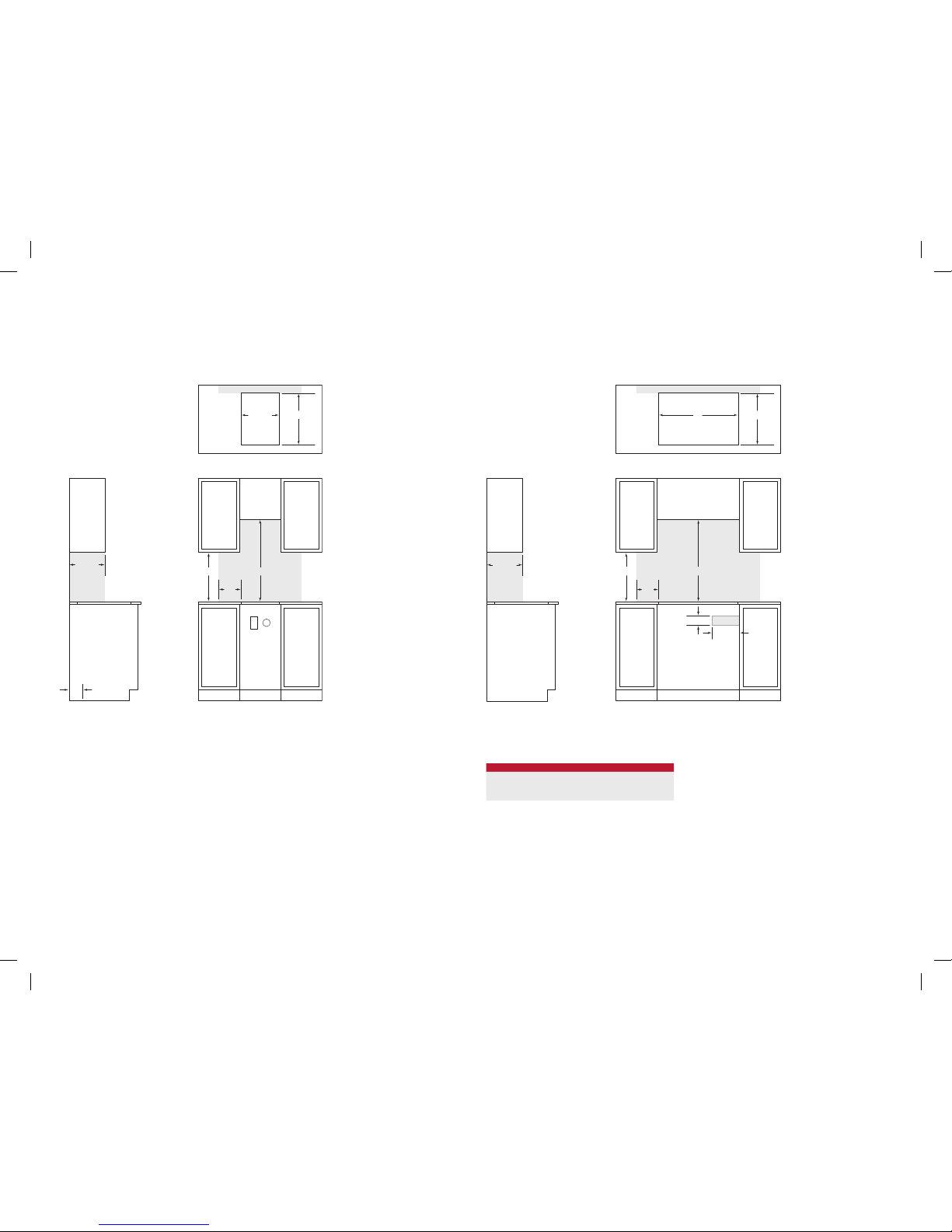
Plaque de cuisson gaz 762 mm et 914 mm
INSTALLATION STANDARD
254 mm
102 mm
89 mm
FRONT VIEW
SIDE
VIEW
COUNTERTOP CUT-OUT
NO
TE: Shaded area above countertop indicates minimum clearance to combustible surfaces,
combus
tible materials cannot be located within this area.
El
ectrical and gas supply location only applies to installations with built-in oven.
762 mm
W
WIDTH
330 mm
457 mm
229
mm
495 mm
64 mm
64 mm
E G
LARGEUR DE LA DÉCOUPE
MODÈLE L
Plaque de cuisson 762 mm 737 mm
Plaque de cuisson 914 mm 889 mm
FRONT VIEWSIDE VIEW
COUNTERTOP CUT-OUT
NOTE: Shaded area above countertop indicates minimum clearance to combustible surfaces,
combustible materials cannot be located within this area.
330 mm
457 mm
178
mm
E G
127
mm
ELECTRICAL
AND GAS FLOOR
LOCATION
762 mm
356 mm
495 mm
64 mm
64 mm
Plaque de cuisson gaz 381 mm
INSTALLATION STANDARD
DÉCOUPE DU PLAN
DE TRAVAIL
LARGEUR
VUE DE FACEVUE LATÉRALE
DÉCOUPE DU PLAN DE TRAVAIL
VUE DE FACE
VUE LATÉRALE
REMARQUE: La zone ombrée au-dessus du plan de travail indique l'espace minimum à conserver par
rapport aux surfaces combustibles. Il ne peut y avoir aucun matériau combustible dans cette zone.
REMARQUE: La zone ombrée au-dessus du plan de travail indique l'espace minimum à conserver par rapport aux surfaces combustibles.
Il ne peut y avoir aucun matériau combustible dans cette zone.
Les emplacements de l'alimentation en gaz et en électricité ne s'appliquent qu'aux installations avec four encastré.
EMPLACEMENT AU SOL
DE L'ALIMENTATION
EN ÉLECTRICITÉ
ET EN GAZ
L
WF Intl GCooktops IG MultiLang 824551A 10-13.indd 4 2/19/14 12:08 PM
Page 13
wolfappliance.com | 5
Wolf, Wolf & Design, Wolf Gourmet, W & Design et la couleur rouge comme celle qui est appliquée aux boutons sont des marques déposées et des marques de services de Wolf Appliance, Inc. Sub-Zero, Sub-Zero & Design, Dual Refrigeration, Constant Care, The Living Kitchen, Great American Kitchens The Fine Art of Kitchen Design et Ingredients sont des marques
déposées et des marques de services de Sub-Zero, Inc. (collectivement, les « marques d'entreprise »). Toutes les autres marques de commerce ou marques déposées ont été brevetées par leurs propriétaires respectifs aux États-Unis ou dans d'autres pays.
Installation de la plaque de cuisson
Retirez la plaque de cuisson ainsi que les accessoires de
l'emballage et recyclez les matériaux d'emballage.
Abaissez la plaque de cuisson dans l'ouverture découpée
dans le plan de travail. Centrez la plaque de cuisson dans
l'ouverture avec le bord avant parallèle au bord avant du
plan de travail. Avec un crayon, tracez l'emplacement du
bord arrière de la plaque de cuisson sur le plan de travail.
Retirez la plaque de cuisson.
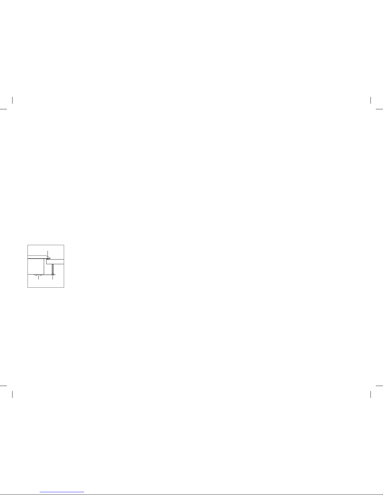
Fixez la bande de mousse fournie sur le périmètre de
l'ouverture du plan de travail. Reportez-vous à l'illustration
ci-après. Ne scellez pas la plaque de cuisson au plan de
travail.
Replacez la plaque de cuisson dans l'ouverture découpée.
Assurez-vous que la plaque de cuisson est alignée sur le
bord avant du plan de travail.
Fixez les supports fournis à la base de l'appareil. Insérez les
vis de blocage de 89 mm dans les supports. A l'aide d'un
tournevis, serrez les vis de blocage contre le dessous du
plan de travail. Ne serrez pas trop les vis. Reportez-vous à
l'illustration ci-après.
INSTALLATION
Branchement de l'alimentation en gaz
Tous les raccordements vers les conduites de gaz doivent
être serrés avec une clé. Ne serrez pas trop et faites en
sorte que les conduites ne tournent pas lorsque vous les
serrez.
Si vous utilisez un raccord en métal souple, vériez qu'il
n'est pas tordu, puis xez la conduite d'alimentation en gaz
au régulateur sur la plaque de cuisson. Ouvrez le robinet et
utilisez une solution de détergent liquide pour tester tous les
raccordements an de déceler les fuites de gaz éventuelles.
La formation de bulles autour des raccordements indique la
présence d'une fuite de gaz. Si une fuite apparaît, fermez le
robinet du gaz et ajustez les raccordements.
Dépistage des pannes
REMARQUE IMPORTANTE : Si la plaque de cuisson ne fonc-
tionne pas correctement, suivez les étapes de dépistage
des pannes suivantes :
• Vériez si l'alimentation électrique arrive à la plaque de
cuisson.
• Vériez que le robinet d'arrêt de l'alimentation en gaz est
en position ouverte.
• Si la plaque de cuisson ne fonctionne pas correcte-
ment, contactez un prestataire agréé par l'usine Wolf.
N'essayez pas de réparer le four. Wolf ne peut être tenue
responsable des dépannages requis en raison d'une
mauvaise installation.
FOAM STRIP
COUNTERTOP
BRACKET
CLAMPING
SCREW
Installation de la plaque de cuisson.
BANDE DE
MOUSSE
SUPPORT VIS DE
BLOCAGE
PLAN DE TRAVAIL
WF Intl GCooktops IG MultiLang 824551A 10-13.indd 5 2/19/14 12:08 PM
Page 14
2 | Italiano
PIANI COTTURA A GAS
Indice
2 Piani cottura a gas
3 Speciche
5 Installazione
5 Risoluzione dei problemi
Le caratteristiche e le speciche sono soggette a modiche
in qualsiasi momento, senza obbligo di preavviso. Visitare
la pagin web wolfappliance.com/specs, per informazioni
aggiornate.
Informazioni sul prodotto
Sulla targhetta identicativa del prodotto sono riportate
informazioni importanti tra cui il modello e il numero di serie.
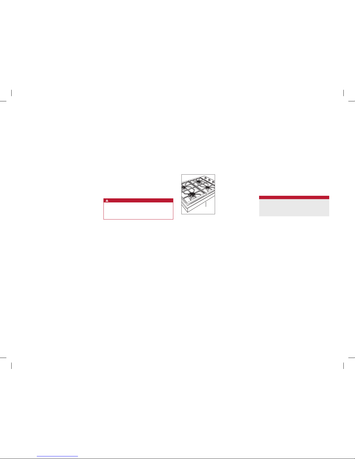
La targhetta identicativa si trova sotto il piano cottura. Fare
riferimento alla gura riportata di seguito.
Se si rende necessaria l'assistenza, rivolgersi al servizio di
assistenza certicato Wolf specicando modello e numero
di serie.
Nota importante
Per garantire l'installazione e il funzionamento sicuri ed
efcaci di questo prodotto, prestare attenzione alle seguenti
informazioni evidenziate nella guida:
NOTA IMPORTANTE evidenzia informazioni di particolare
rilievo.
ATTENZIONE indica una situazione che potrebbe compor-
tare lievi lesioni alle persone o danni al prodotto in caso di
mancata osservanza delle istruzioni.
AVVERTENZA indica una situazione di pericolo che potrebbe
causare gravi lesioni o morte in caso di mancata osservanza
delle precauzioni.
NOTA IMPORTANTE: conservare le presenti istruzioni per
eventuali ispezioni elettriche.
AVVERTENZA
Questo elettrodomestico deve essere installato
secondo le normative vigenti ed usato solo in un
ambiente ben ventilato. Leggere le istruzioni prima di
installare o utilizzare l'elettrodomestico.
Posizione della targhetta
identicativa.
TARGHETTA
IDENTIFICATIVA
Requisiti di installazione
Se il piano cottura è installato sopra un forno, occorre
lasciare uno spazio di almeno 6 mm tra i due elettrodomestici. Tra la parte inferiore del piano cottura e le superci
combustibili occorre lasciare uno spazio di almeno 140 mm.
Alimentazione elettrica
L'installazione deve essere conforme alle normative elettriche vigenti in materia.
Individuare la presa di alimentazione elettrica come illustrato
nelle gure a pagina 4. È necessario predisporre un circuito
elettrico dedicato per questo elettrodomestico. Si sconsiglia
l'utilizzo di un interruttore automatico salvavita (GFCI) in
quanto si potrebbero vericare problemi di funzionamento.
REQUISITI ELETTRICI
PIANO COTTURA A GAS
Alimentazione elettrica a terra
220-240 VCA, 50/60 Hz
Alimentazione Circuito dedicato da 10 A
Presa di corrente Con messa a terra
NOTA IMPORTANTE: questo elettrodomestico va collegato
all'alimentazione tramite una connessione dotata di fusibili o
un adeguato interruttore di isolamento, conforme alle vigenti
normative di sicurezza nazionali e locali. L'interruttore di
accensione/spegnimento deve essere facilmente accessibile
dopo aver installato l'elettrodomestico. Se dopo l'installazione, l'interruttore non è accessibile, sarà necessario
installare (in base alle normative del proprio paese) un ulteriore dispositivo per scollegare tutti i poli dell'alimentazione.
Quando è scollegato, tutti i poli all'interno dell'interruttore di
isolamento devono presentare uno spazio libero ai contatti
di almeno 3 mm. Lo spazio libero ai contatti di 3 mm deve
essere rispettato in tutti gli interruttori di isolamento, fusibili
e/o relè in ottemperanza alla normativa EN60335.
WF Intl GCooktops IG MultiLang 824551A 10-13.indd 2 2/19/14 12:08 PM
Page 15
wolfappliance.com | 3
SPECIFICHE
Allacciamento del gas
L'installazione deve essere conforme alle normative e alle
ordinanze vigenti a livello locale.
Individuare la linea di alimentazione del gas come illustrato
nelle gure a pagina 4.
Il piano cottura è attrezzato per l'uso con gas propano naturale o liquido (GPL). La targhetta identicativa del prodotto
contiene le informazioni sul tipo di gas da usare. Per la
posizione della targhetta identicativa, fare riferimento alla
gura di seguito. Se queste informazioni non sono conformi
al tipo di gas disponibile, rivolgersi all'azienda fornitrice del
gas di zona.
Prima dell'installazione, accertarsi che le condizioni di
distribuzione locale (tipo e pressione del gas) e la regolazione dell'elettrodomestico siano compatibili. Le condizioni
di regolazione per questo elettrodomestico sono indicate
sull'etichetta (o sulla targhetta identicativa). La targhetta
identicativa si trova sotto il piano cottura.
Questo elettrodomestico non è collegato ad un dispositivo
di evacuazione di prodotti a combustione. Va installato e
collegato secondo le normative vigenti al momento dell'installazione. Prestare particolare attenzione ai requisiti di
pertinenza relativi alla ventilazione.
REQUISITI DELL'ALLACCIAMENTO DEL GAS
GAS NATURALE
Pressione di erogazione del gas 12,5 mbar
Pressione min. linea 17,5 mbar
Pressione massima al regolatore 100 mbar
GAS GPL
Pressione di erogazione del gas 25 mbar
Pressione min. linea 27,4 mbar
Pressione massima al regolatore 100 mbar
PORTATA GAS
MODELLO
TOTALE
USCITA
CALORE
UNITÀ A
GAS
CATEGORIA
ELETTRO-
DOMESTICO
TIPI E PRESSIONI
(mbar) PAESE DI DESTINAZIONE
ICBGC152T/S 6,2 kW
I2H G20 a 20
AT, BG, CR, CZ, DK, EE, FI, GR, HR, HU, IS, IE, IT, LV, LT,
NO, PT, RO, SK, SI, ES, SE, CH, TR, GB
I2E G20 a 20 DE, LU, PL
I2E+ G20 a 20/25 BE, FR
ICBCG152T/S/LP 1594 g/h I3P G31 a 37 FI, CR, GR, IE, HR, LU, NL, PL, SK, SI, ES, CH, TR, GB
ICBCG304T/S 14,2 kW
I2H G20 a 20
AT, BG, CR, CZ, DK, EE, FI, GR, HR, HU, IS, IE, IT, LV, LT,
NO, PT, RO, SK, SI, ES, SE, CH, TR, GB
I2E G20 a 20 DE, LU, PL
I2E+ G20 a 20/25 BE, FR
ICBCG304T/S/LP 3651 g/h I3P G31 a 37 FI, CR, GR, IE, HR, LU, NL, PL, SK, SI, ES, CH, TR, GB
ICBCG304P/S 14,2 kW
I2H G20 a 20
AT, BG, CR, CZ, DK, EE, FI, GR, HR, HU, IS, IE, IT, LV, LT,
NO, PT, RO, SK, SI, ES, SE, CH, TR, GB
I2E G20 a 20 DE, LU, PL
I2E+ G20 a 20/25 BE, FR
ICBCG304P/S/LP 3651 g/h I3P G31 a 37 FI, CR, GR, IE, HR, LU, NL, PL, SK, SI, ES, CH, TR, GB
ICBCG365T/S 16,9 kW
I2H G20 a 20
AT, BG, CR, CZ, DK, EE, FI, GR, HR, HU, IS, IE, IT, LV, LT,
NO, PT, RO, SK, SI, ES, SE, CH, TR, GB
I2E G20 a 20 DE, LU, PL
I2E+ G20 a 20/25 BE, FR
ICBCG365T/S/LP 4345 g/h I3P G31 a 37 FI, CR, GR, IE, HR, LU, NL, PL, SK, SI, ES, CH, TR, GB
ICBCG365P/S 16,9 kW
I2H G20 a 20
AT, BG, CR, CZ, DK, EE, FI, GR, HR, HU, IS, IE, IT, LV, LT,
NO, PT, RO, SK, SI, ES, SE, CH, TR, GB
I2E G20 a 20 DE, LU, PL
I2E+ G20 a 20/25 BE, FR
ICBCG365P/S/LP 4345 g/h I3P G31 a 37 FI, CR, GR, IE, HR, LU, NL, PL, SK, SI, ES, CH, TR, GB
Il piano cottura deve essere collegato ad una rete del gas
regolata. La rete del gas deve essere dotata di una valvola
di arresto del gas approvata in prossimità del piano cottura
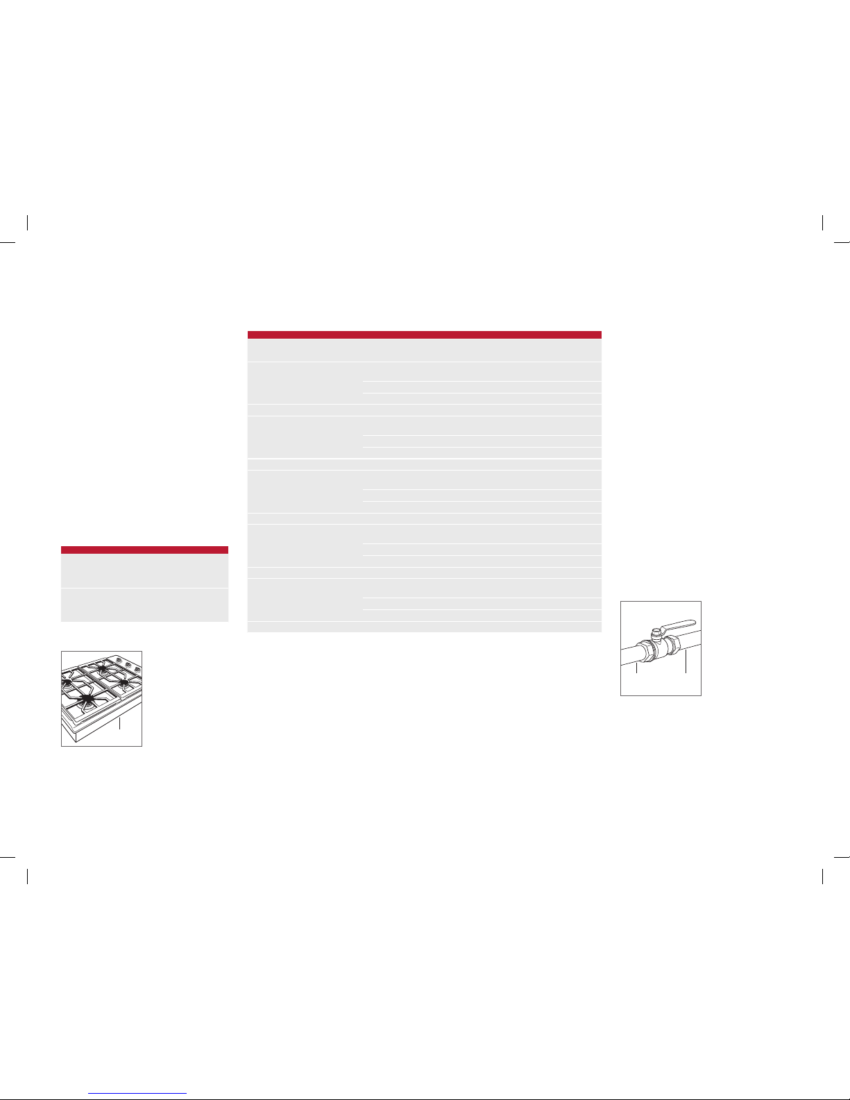
in un punto di facile accesso. Non bloccare l'accesso alla
valvola di arresto. Fare riferimento alla gura riportata di
seguito.
L'utente deve predisporre un tubo del gas a norma da
19 mm da allacciare al piano cottura. Se consentito dalle
normative locali, si consiglia di utilizzare un connettore
metallico essibile lungo 0,9 metri, con diametro interno di
13 mm o 19 mm per collegare l'entrata maschio da 1/2" NPT
(o ISO 7/1-14) dell'unità alla linea di alimentazione del gas.
Utilizzare solo composti per giunti adeguati all'uso con gas
naturale o GLP.
L'elettrodomestico e la sua valvola di arresto devono essere
scollegati dal tubo di alimentazione del gas durante ogni
test del sistema a pressioni superiori a 100 mbar. L'elettrodomestico deve essere isolato dal tubo di alimentazione
del gas chiudendo la relativa valvola di arresto manuale
durante qualsiasi test del sistema a pressioni pari o inferiori
a 100mbar.
I piani cottura a gas naturale Wolf funzionano no a 3124 m
di altitudine senza regolazione, mentre i piani cottura a GLP
funzionano no a 2621 m. Se l'elettodomestico viene installato ad altitudini superiori, contattare il rivenditore autorizzato Wolf presso cui è stato effettuato l'acquisto e richiedere
un kit di conversione per l'alta quota.
Posizione della targhetta
identicativa.
TARGHETTA
IDENTIFICATIVA
SHUT-OFF VALVE
OPEN POSITION
GAS SUPPLYTO APPLIANCE
Valvola di arresto.
TUBO DI
EROGAZIONE
DEL GAS
TUBO DI
COLLEGAMENTO
ALL'ELETTRODO-
MESTICO
VALVOLA DI
ARRESTO APERTA
WF Intl GCooktops IG MultiLang 824551A 10-13.indd 3 2/19/14 12:08 PM
Page 16
4 | Italiano
SPECIFICHE
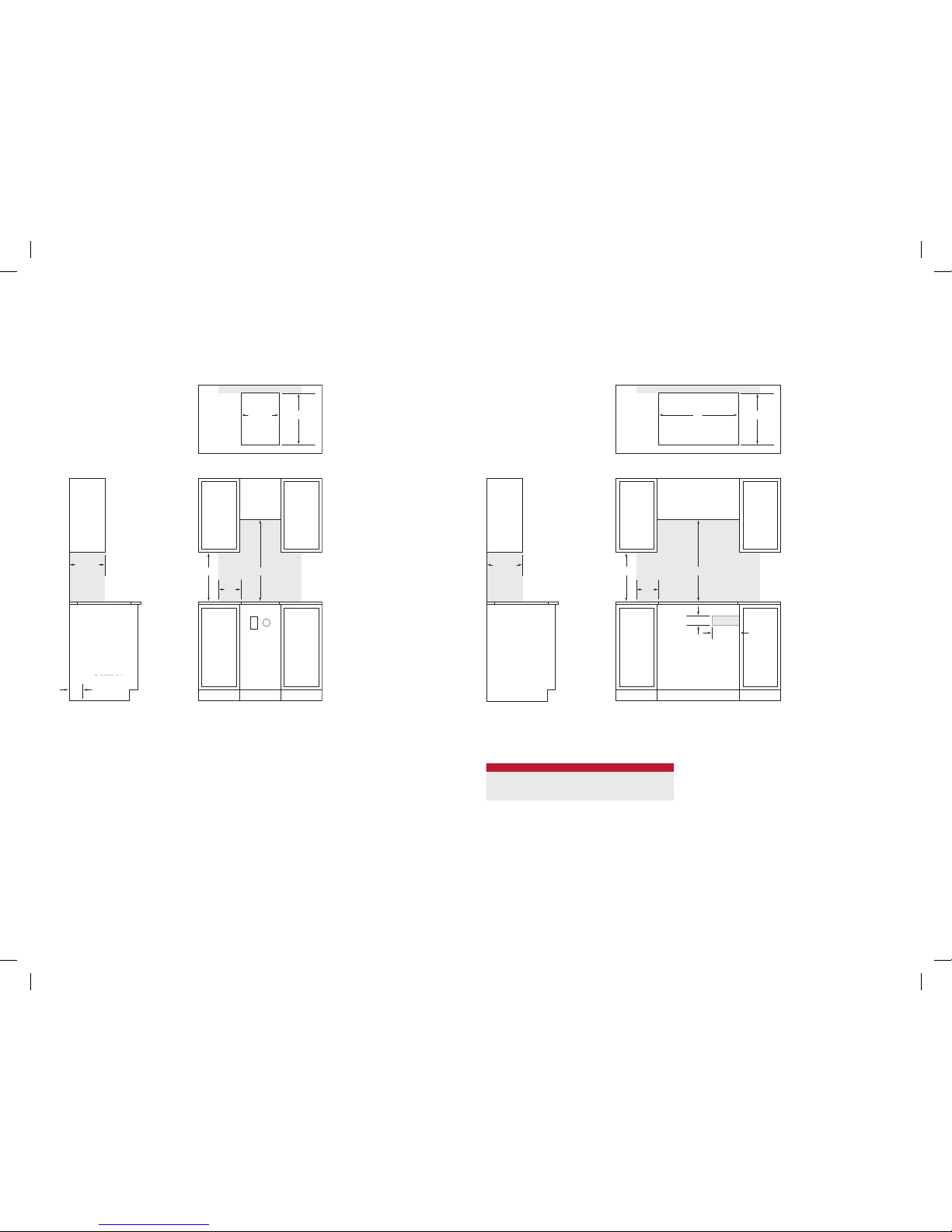
Piano cottura a gas da 762 mm e 914 mm
INSTALLAZIONE STANDARD
254 mm
102 mm
89 mm
FRONT VIEW
SIDE
VIEW
COUNTERTOP CUT-OUT
NO
TE: Shaded area above countertop indicates minimum clearance to combustible surfaces,
combus
tible materials cannot be located within this area.
El
ectrical and gas supply location only applies to installations with built-in oven.
762 mm
W
WIDTH
330 mm
457 mm
229
mm
495 mm
64 mm
64 mm
E G
LARGHEZZA VANO INCASSO
MODELLO L
Piano cottura da 762 mm 737 mm
Piano cottura da 914 mm 889 mm
FRONT VIEWSIDE VIEW
COUNTERTOP CUT-OUT
NOTE: Shaded area above countertop indicates minimum clearance to combustible surfaces,
combustible materials cannot be located within this area.
330 mm
457 mm
178
mm
E G
127
mm
ELECTRICAL
AND GAS FLOOR
LOCATION
762 mm
356 mm
495 mm
64 mm
64 mm
Piano cottura a gas da 381 mm
INSTALLAZIONE STANDARD
VANO DI INCASSO DEL
PIANO DI LAVORO
LARGHEZZA
VISTA FRONTALEVISTA LATERALE
VANO DI INCASSO DEL PIANO DI LAVORO
VISTA FRONTALEVISTA LATERALE
NOTA: l'area ombreggiata sopra il piano indica la distanza minima rispetto alle superci combustibili;
all'interno di quest'area non è possibile collocare materiali combustibili
NOTA: l'area ombreggiata sopra il piano indica la distanza minima rispetto alle superci combustibili; all'interno di
quest'area non è possibile collocare materiali combustibili.
La posizione delle prese di erogazione elettrica e del gas si applica solo alle installazioni con forno incorporato.
POSIZIONE DELLA
PRESA ELETTRICA
E DEL GAS
L
WF Intl GCooktops IG MultiLang 824551A 10-13.indd 4 2/19/14 12:08 PM
Page 17
wolfappliance.com | 5
Wolf, Wolf & Design, Wolf Gourmet, W & Design e il colore rosso applicato alle manopole sono marchi registrati e di servizio di Wolf Appliance, Inc. Sub-Zero, Sub-Zero & Design, Dual Refrigeration, Constant Care, The Living Kitchen, Great American Kitchens The Fine Art of Kitchen Design e Ingredients sono marchi registrati e di servizio di Sub-Zero, Inc. (indicati collettivamente con "Marchi aziendali"). Tutti gli altri marchi o marchi registrati sono di proprietà dei rispettivi titolari negli Stati Uniti e in altri paesi.
Installazione del piano cottura
Rimuovere il piano cottura e i relativi componenti dalla confezione e riciclare i materiali di imballaggio.
Inserire il piano cottura nel vano incasso del piano di lavoro.
Centrare il piano cottura nell'apertura con il bordo anteriore
allineato a quello anteriore del piano di lavoro. Con una
matita delineare il bordo posteriore del piano cottura sul
piano di lavoro. Rimuovere il piano cottura.
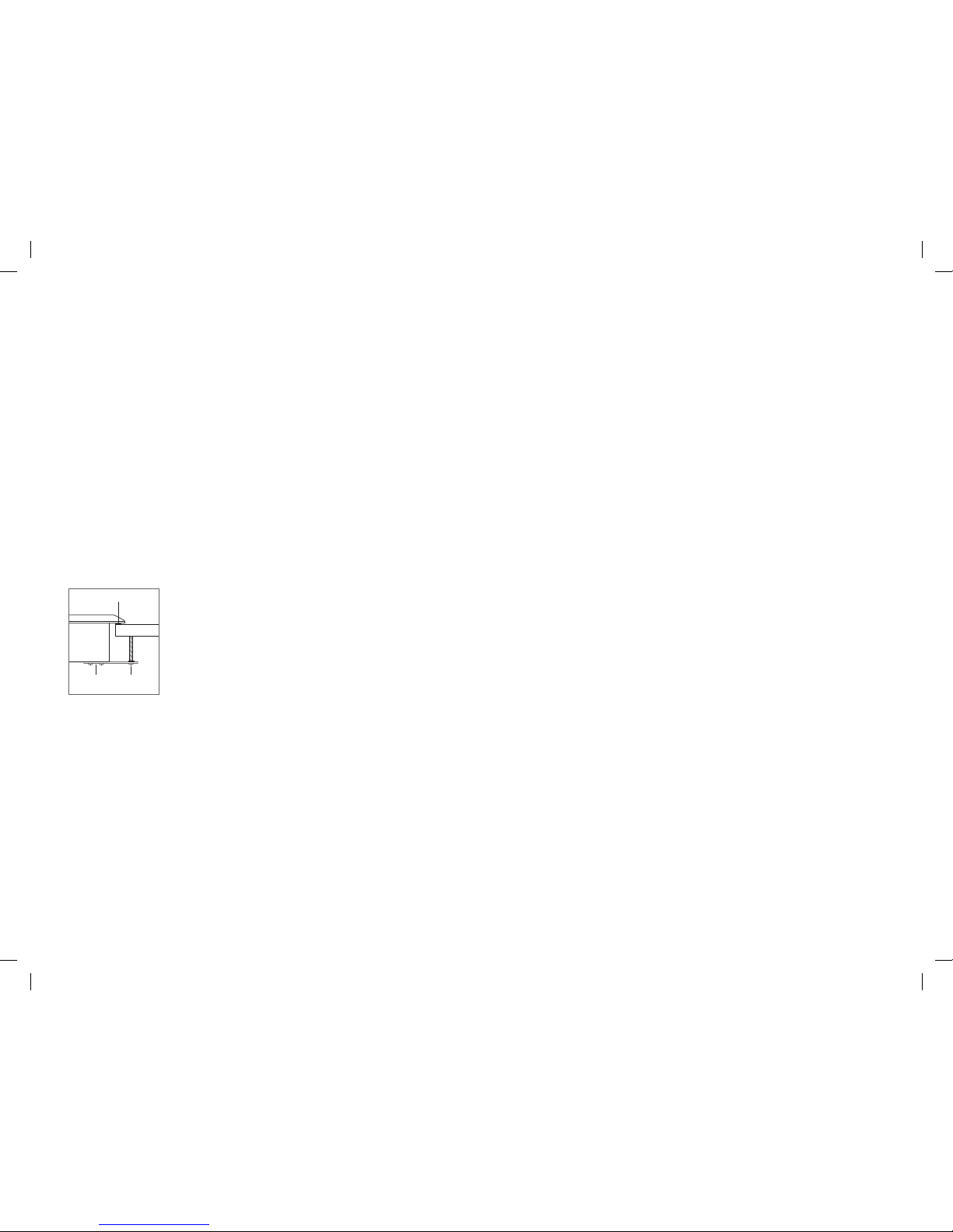
Applicare la striscia di schiuma fornita sul perimetro dell'
apertura del piano di lavoro. Fare riferimento alla gura
riportata di seguito. Non incollare il piano cottura al piano di
lavoro.
Inserire il piano cottura nell'apertura. Controllare che il piano
cottura sia allineato al bordo anteriore del piano di lavoro.
Fissare le piastre fornite alla parte inferiore dell'elettrodomestico. Inserire le viti di blocco da 89 mm nelle piastre. Usare
un cacciavite per serrare le viti di blocco contro la parte
inferiore del piano di lavoro. Non serrare eccessivamente le
viti. Fare riferimento alla gura riportata di seguito.
INSTALLAZIONE
Allacciamento del gas
Tutti i collegamenti con il tubo del gas devono essere serrati
con una chiave. Non stringere troppo e consentire ai tubi di
ruotare durante il serraggio.
Se si utilizza un connettore essibile in metallo, accertarsi
che non sia piegato, quindi collegare la linea di alimentazione del gas al regolatore sul piano cottura. Aprire la
valvola e vericare eventuali perdite mettendo un detergente liquido su tutti i collegamenti del gas. La presenza di
bollicine intorno ai punti di collegamento indica una perdita.
In caso di perdite, chiudere la valvola di arresto del gas e
regolare i collegamenti.
Risoluzione dei problemi
NOTA IMPORTANTE: se il piano cottura non funziona corret-
tamente, effettuare le seguenti operazioni.
• Vericare che il piano cottura riceva alimentazione
elettrica.
• Vericare che la valvola di arresto sia aperta.
• Se il piano cottura non funziona adeguatamente, rivol-
gersi a un centro di assistenza autorizzato Wolf. Non
tentare di riparare il piano cottura. Wolf non è tenuta a
fornire l'assistenza necessaria a correggere un'installazione difettosa.
FOAM STRIP
COUNTERTOP
BRACKET
CLAMPING
SCREW
Installazione del piano cottura.
STRISCIA DI
SCHIUMA
PIASTRA VITE DI
BLOCCO
PIANO DI LAVORO
WF Intl GCooktops IG MultiLang 824551A 10-13.indd 5 2/19/14 12:08 PM
Page 18
2 | Deutsch
GASKOCHMULDEN
Inhaltsverzeichnis
2 Gaskochmulden
3 Technische Daten
5 Installation
5 Fehlersuche
Die Leistungsmerkmale und technischen Daten unterliegen
jederzeit Änderungen ohne Vorankündigung. Die aktuellsten
Informationen nden Sie unter wolfappliance.com/specs.
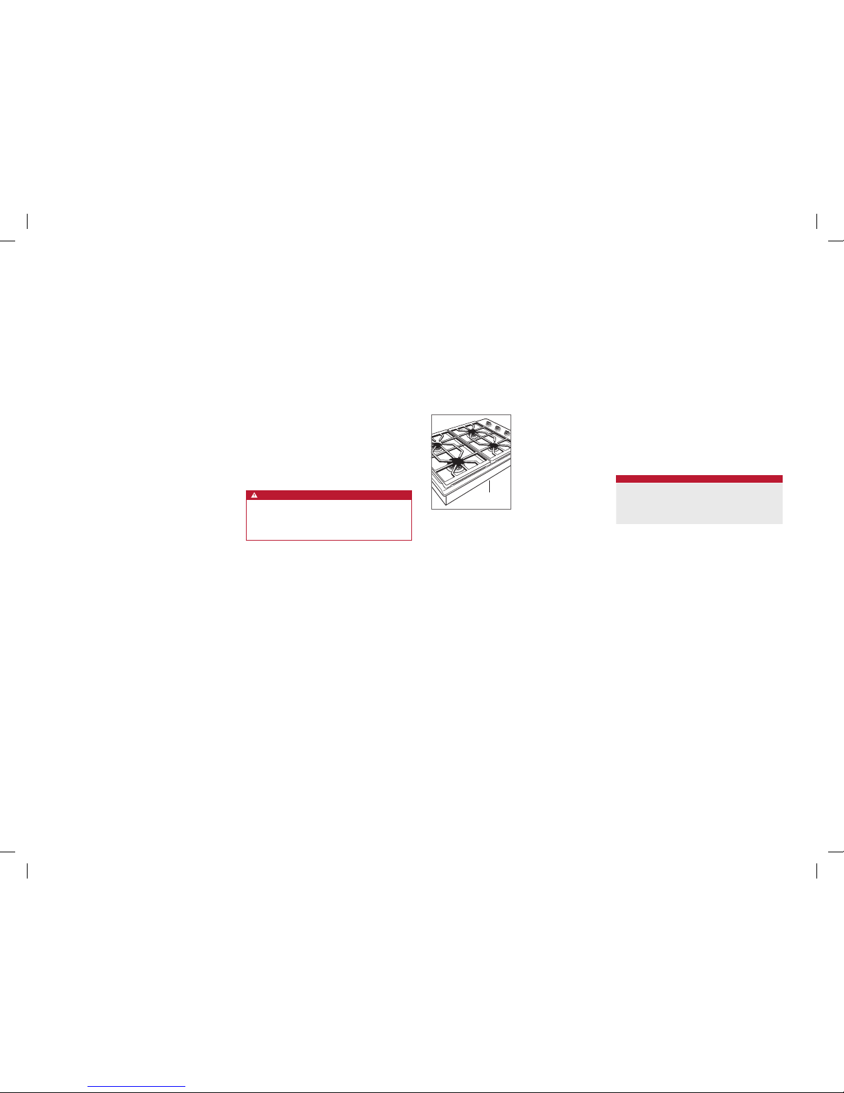
Produktinformationen
Wichtige Produktinformationen, einschließlich der Modellund Seriennummer, sind auf dem Produkttypenschild aufgeführt. Das Typenschild bendet sich auf der Unterseite der
Kochmulde. Siehe Abbildung unten.
Wenn Servicearbeiten erforderlich sind, wenden Sie sich
mit der Modell- und Seriennummer an ein zugelassenes
Wolf-Kundendienstzentrum.
Wichtiger Hinweis
Um eine möglichst sichere und efziente Installation dieses
Produkts zu gewährleisten, beachten Sie bitte die folgenden
Arten hervorgehobener Informationen in der gesamten
Anleitung:
WICHTIGER HINWEIS hebt Informationen hervor, die beson-
ders wichtig sind.
VORSICHT ist ein Hinweis auf eine Situation, die bei Nicht-
beachtung der Anweisungen zu geringfügigen Personenoder Sachschäden führen kann.
ACHTUNG weist auf eine Gefahr hin, die bei Nichtbeachtung
der Anweisungen zu schweren Verletzungen oder zum Tod
führen kann.
WICHTIGER HINWEIS: Bewahren Sie diese Installationsan-
weisungen für den Gebrauch seitens des örtlichen Elektroprüfers auf.
ACHTUNG
Dieses Gerät ist gemäß geltender Vorschriften zu
installieren und darf nur in einem gut belüfteten Raum
verwendet werden. Vor der Installation bzw. der Verwendung dieses Geräts die Anweisungen lesen.
Typenschildposition.
TYPENSCHILD
Installationsvoraussetzungen
Wenn eine Kochmulde über einem Backofen installiert wird,
ist zwischen den Geräten ein Mindestabstand von 6mm
erforderlich. Von der Unterseite der Kochmulde bis zu
brennbaren Materialien ist ein Mindestabstand von 140mm
erforderlich.
Elektrik
Bei der Installation müssen alle geltenden elektrischen Vorschriften eingehalten werden.
Installieren Sie die Stromversorgung im Bereich, der in
den Zeichnungen auf Seite 4 dargestellt ist. Außerdem ist
ein separater Stromkreis nur für dieses Gerät erforderlich.
Ein FI-Schutzschalter wird nicht empfohlen und kann den
Betrieb unterbrechen.
ELEKTROVORAUSSETZUNGEN
GASKOCHMULDE
Stromversorgung geerdet
220-240 V AC, 50/60 Hz
Versorgung 10 A, dedizierter Stromkreis
Steckdose geerdet
WICHTIGER HINWEIS: Der Anschluss dieses Geräts sollte
über ein Sicherungsmodul oder einen geeigneten Trennschalter vorgenommen werden, das bzw. der den nationalen
und örtlichen Sicherheitsvorschriften entspricht. Der Ein-/
Aus-Schalter sollte nach der Installation des Geräts leicht
zugänglich sein. Wenn der Schalter nach der Installation
nicht zugänglich ist (je nach Land), muss für alle Pole
der Stromversorgung eine zusätzliche Trennvorrichtung
bereitgestellt werden. Im ausgeschalteten Zustand muss
im Trennschalter ein allpoliger Kontaktabstand von 3 mm
vorhanden sein. Dieser 3-mm-Kontakttrennabstand muss
für alle Trennschalter, Sicherungen und/oder Relais gemäß
EN60335 eingehalten werden.
WF Intl GCooktops IG MultiLang 824551A 10-13.indd 2 2/19/14 12:08 PM
Page 19
wolfappliance.com | 3
TECHNISCHE DATEN
Gasversorgung
Die Installation muss allen örtlichen Vorschriften und Richtlinien entsprechen.
Installieren Sie die Gasversorgung im Bereich, der in den
Zeichnungen auf Seite 4 dargestellt ist.
Die Kochmulde ist für die Verwendung mit Erdgas oder
Flüssiggas (LP-Gas) ausgestattet. Auf dem Produkttypenschild benden sich Informationen bezüglich des
Gastyps, der verwendet werden sollte. Die Position des
Typenschildes entnehmen Sie der nachstehenden Abbildung. Wenn diese Informationen nicht mit dem verfügbaren
Gas übereinstimmen, wenden Sie sich an Ihr örtliches
Gasversorgungsunternehmen.
Vor der Installation muss geprüft werden, ob die örtlichen
Verteilungsbedingungen (Gastyp und Gasdruck) und die
Einstellung des Geräts miteinander kompatibel sind. Die
Einstellungsbedingungen für dieses Gerät sind auf dem
Aufkleber (oder dem Typenschild) aufgeführt. Das Schild mit
den entsprechenden Daten bendet sich auf der Unterseite
der Kochmulde.
Dieses Gerät wird nicht an eine Abgaseinrichtung für
Verbrennungsprodukte angeschlossen. Es muss nach den
geltenden Installationsvorschriften eingebaut und angeschlossen werden. Besonders zu beachten sind die entsprechenden Anforderungen an die Entlüftung.
VORAUSSETZUNGENFÜR DIE GASVERSORGUNG
ERDGAS
Gaszufuhrdruck 12,5 mb
Mind.-Leitungsdruck 17,5 mb
Max. Druck zum Regler 100 mb
FLÜSSIGGAS
Gaszufuhrdruck 25 mb
Mind.-Leitungsdruck 27,4 mb
Max. Druck zum Regler 100 mb
GASNENNLEISTUNG
MODELL
WÄRMEGESAMT-
LEISTUNG GASEINHEITEN
GERÄTEKATE-
GORIE
TYPEN UND
DRÜCKE (mbar) ZIELLAND
ICBGC152T/S 6,2 kW
I2H G20 bei 20
AT, BG, CR, CZ, DK, EE, FI, GR, HR, HU, IS,
IE, IT, LV, LT, NO, PT, RO, SK, SI, ES, SE, CH,
TR, GB
I2E G20 bei 20 DE, LU, PL
I2E+ G20 bei 20/25 BE, FR
ICBCG152T/S/LP 1594 g/h I3P G31 bei 37
FI, CR, GR, IE, HR, LU, NL, PL, SK, SI, ES, CH,
TR, GB
ICBCG304T/S 14,2 kW
I2H G20 bei 20
AT, BG, CR, CZ, DK, EE, FI, GR, HR, HU, IS,
IE, IT, LV, LT, NO, PT, RO, SK, SI, ES, SE, CH,
TR, GB
I2E G20 bei 20 DE, LU, PL
I2E+ G20 bei 20/25 BE, FR
ICBCG304T/S/LP 3651 g/h I3P G31 bei 37
FI, CR, GR, IE, HR, LU, NL, PL, SK, SI, ES, CH,
TR, GB
ICBCG304P/S 14,2 kW
I2H G20 bei 20
AT, BG, CR, CZ, DK, EE, FI, GR, HR, HU, IS,
IE, IT, LV, LT, NO, PT, RO, SK, SI, ES, SE, CH,
TR, GB
I2E G20 bei 20 DE, LU, PL
I2E+ G20 bei 20/25 BE, FR
ICBCG304P/S/LP 3651 g/h I3P G31 bei 37
FI, CR, GR, IE, HR, LU, NL, PL, SK, SI, ES, CH,
TR, GB
ICBCG365T/S 16,9 kW
I2H G20 bei 20
AT, BG, CR, CZ, DK, EE, FI, GR, HR, HU, IS,
IE, IT, LV, LT, NO, PT, RO, SK, SI, ES, SE, CH,
TR, GB
I2E G20 bei 20 DE, LU, PL
I2E+ G20 bei 20/25 BE, FR
ICBCG365T/S/LP 4345 g/h I3P G31 bei 37
FI, CR, GR, IE, HR, LU, NL, PL, SK, SI, ES, CH,
TR, GB
ICBCG365P/S 16,9 kW
I2H G20 bei 20
AT, BG, CR, CZ, DK, EE, FI, GR, HR, HU, IS,
IE, IT, LV, LT, NO, PT, RO, SK, SI, ES, SE, CH,
TR, GB
I2E G20 bei 20 DE, LU, PL
I2E+ G20 bei 20/25 BE, FR
ICBCG365P/S/LP 4345 g/h I3P G31 bei 37
FI, CR, GR, IE, HR, LU, NL, PL, SK, SI, ES, CH,
TR, GB
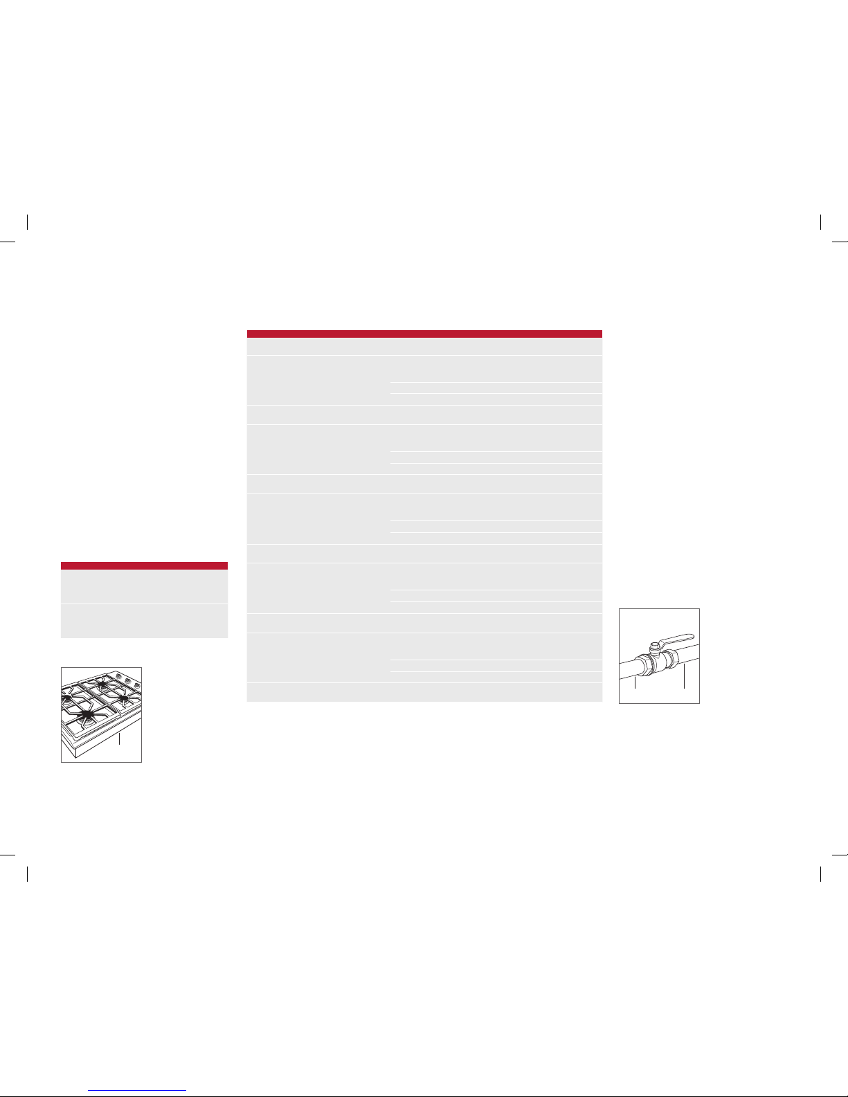
Die Kochmulde muss an einer geregelten Gasversorgung
angeschlossen werden. Die Versorgungsleitung muss mit
einem zugelassenen externen Gasabsperrventil ausgestattet
sein, das sich in der Nähe der Kochmulde an einem zugänglichen Ort bendet. Der Zugang zum Absperrventil darf nicht
blockiert werden. Siehe Abbildung unten.
Die Gaszufuhr zur Kochmulde muss über ein 19 mm großes
starres Rohr erfolgen. Wenn es die örtlichen Vorschriften
gestatten, wird ein zertizierter, 0,9m langer Flexmetallanschluss mit einem Innendurchmesser von 13mm oder
19mm empfohlen, um das 1/2-Zoll-NPT-Außengewinde
(oder ISO 7/1-14) des Geräts an die Gaszufuhrleitung
anzuschließen. Es sollten Dichtungsmassen für Rohrverschraubungen verwendet werden, die zur Verwendung mit
Erd- oder Flüssiggas kompatibel sind.
Das Gerät und das dazugehörige Absperrventil müssen für
die Durchführung von Drucktests am System bei Testdrücken von mehr als 100mbar vom Versorgungsrohrsystem
abgetrennt werden. Für die Durchführung von Drucktests
am System bei Testdrücken von bis zu 100mbar muss das
Gerät vom Gasversorgungs-Rohrsystem isoliert werden,
indem das manuelle Absperrventil geschlossen wird.
Erdgaskochmulden von Wolf funktionieren bis zu einer
Höhenlage von 3124m ohne jegliche Justierung, und
Flüssiggaskochmulden funktionieren bis zu einer Höhenlage
von 2621m. Wenn die Installation in höheren Höhenlagen
erfolgen soll, wenden Sie sich an Ihren Wolf-Vertragshändler
zwecks Bestellung eines Umbausets für große Höhen.
Typenschildposition.
TYPENSCHILD
SHUT-OFF VALVE
OPEN POSITION
GAS SUPPLYTO APPLIANCE
Gasabsperrventil.
GASVERSORGUNG
ZUM GERÄT
OFFENE POSITION DES
ABSPERRVENTILS
WF Intl GCooktops IG MultiLang 824551A 10-13.indd 3 2/19/14 12:08 PM
Page 20
4 | Deutsch
TECHNISCHE DATEN
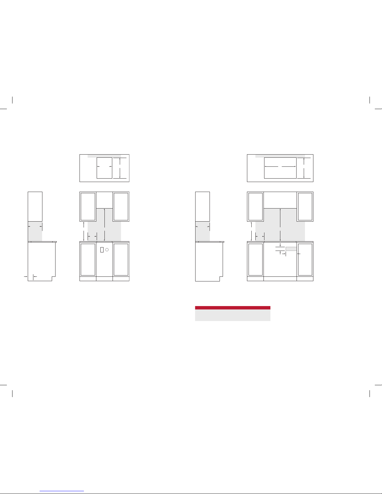
762-mm- und 914-mm-Gaskochmulde
STANDARDINSTALLATION
254 mm
102 mm
89 mm
FRONT VIEW
SIDE
VIEW
COUNTERTOP CUT-OUT
NO
TE: Shaded area above countertop indicates minimum clearance to combustible surfaces,
combus
tible materials cannot be located within this area.
El
ectrical and gas supply location only applies to installations with built-in oven.
762 mm
W
WIDTH
330 mm
457 mm
229
mm
495 mm
64 mm
64 mm
E G
AUSSCHNITTBREITE
MODELL B
762-mm-Kochmulde 737 mm
914-mm-Kochmulde 889 mm
FRONT VIEWSIDE VIEW
COUNTERTOP CUT-OUT
NOTE: Shaded area above countertop indicates minimum clearance to combustible surfaces,
combustible materials cannot be located within this area.
330 mm
457 mm
178
mm
E G
127
mm
ELECTRICAL
AND GAS FLOOR
LOCATION
762 mm
356 mm
495 mm
64 mm
64 mm
381-mm-Gaskochmulde
STANDARDINSTALLATION
ARBEITSPLATTENAUSSCHNITT
BREITE
VORDERANSICHTSEITENANSICHT
ARBEITSPLATTENAUSSCHNITT
VORDERANSICHTSEITENANSICHT
HINWEIS: Der schattierte Bereich über der Arbeitsplatte zeigt den Mindestabstand zu brennbaren Oberächen
an. Brennbare Oberächen dürfen nicht in diesem Bereich untergebracht werden.
HINWEIS: Der schattierte Bereich über der Arbeitsplatte zeigt den Mindestabstand zu brennbaren Oberächen
an. Brennbare Oberächen dürfen nicht in diesem Bereich untergebracht werden.
Die Orte der Strom- und Gasversorgung gelten nur für eine Installation mit einem Einbaubackofen.
ORT DER STROM- UND
GASVERSORGUNG
AM BODEN
B
WF Intl GCooktops IG MultiLang 824551A 10-13.indd 4 2/19/14 12:08 PM
Page 21
wolfappliance.com | 5
Wolf, Wolf & Design, Wolf Gourmet, W & Design und die auf Schaltknebel aufgebrachte Farbe Rot sind eingetragene Marken und Servicemarken der Wolf Appliance, Inc. Sub-Zero, Sub-Zero & Design, Dual Refrigeration, Constant Care, The Living Kitchen, Great American Kitchens, The Fine Art of Kitchen Design und Ingredients sind eingetragene Marken und Servicemarken der Sub-Zero, Inc. (zusammen die „Firmenmarken“). Alle anderen Marken oder eingetragenen Marken sind das Eigentum ihrer jeweiligen Besitzer in den Vereinigten Staaten und anderen Ländern.
Installation der Kochmulde
Die Kochmulde und Komponenten aus dem Versandpaket
herausnehmen und die Verpackungsmaterialien dem
Recycling zuführen.
Die Kochmulde in den Arbeitsplattenausschnitt absenken.
Die Kochmulde so in der Öffnung zentrieren, dass die Vorderkante parallel zur Vorderkante der Arbeitsplatte verläuft.
Die hintere Kante der Kochmulde mit einem Bleistift an der
Arbeitsplatte anzeichnen. Die Kochmulde herausnehmen.
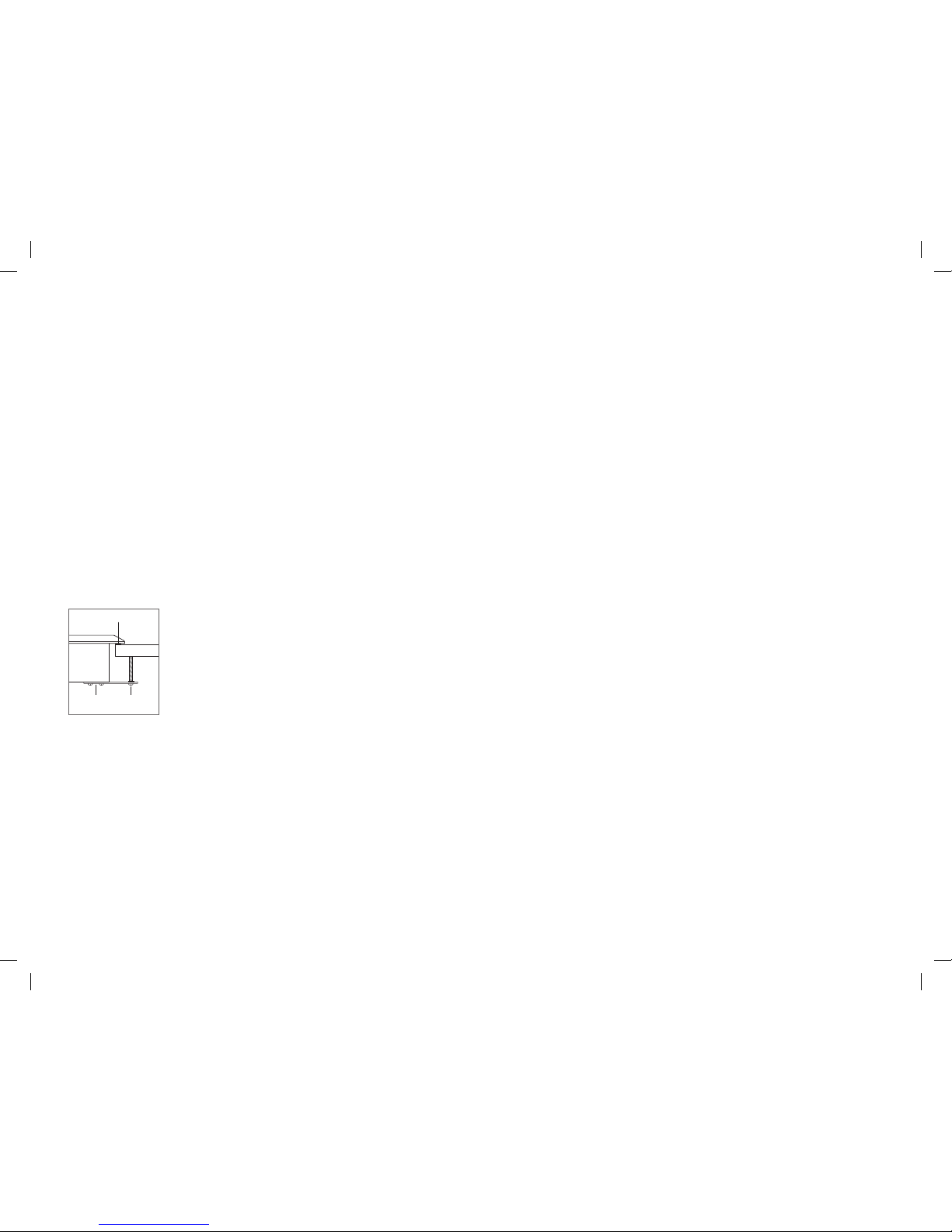
Den mitgelieferten Schaumstreifen am Umfang der Kochmuldenöffnung anbringen. Siehe Abbildung unten. Die
Kochmulde darf nicht an der Arbeitsplatte versiegelt
werden.
Die Kochmulde in die Öffnung einführen. Sicherstellen,
dass die Kochmulde auf die Vorderkante der Arbeitsplatte
ausgerichtet ist.
Die mitgelieferten Halterungen an der Unterseite des Geräts
befestigen. Die 89-mm-Spannschrauben in die Halterungen
einführen. Die Spannschrauben mit einem Schraubendreher an der Unterseite der Arbeitsplatte festziehen. Die
Schrauben nicht zu stark anziehen. Siehe Abbildung unten.
INSTALLATION
Anschlüsse für die Gasversorgung
Alle Anschlüsse an den Gasrohren müssen mit einem
Schraubschlüssel festgezogen werden. Nicht zu fest
anziehen. Außerdem dürfen sich die Rohre beim Anziehen
nicht drehen.
Wenn ein exibler Metallanschluss verwendet wird, muss
sichergestellt werden, dass er nicht geknickt ist. Dann wird
die Gasversorgungsleitung am Regler auf der Kochmulde
angeschlossen. Das Ventil öffnen und auf Lecks prüfen,
indem ein üssiges Spülmittel auf alle Gasanschlüsse
aufgebracht wird. Blasen um die Anschlüsse herum
zeigen an, dass ein Gasleck vorhanden ist. Wenn sich ein
Leck bemerkbar macht, das Gasventil schließen und die
Anschlüsse korrigieren.
Fehlersuche
WICHTIGER HINWEIS: Wenn die Kochmulde nicht richtig
funktioniert, führen Sie zur Fehlersuche folgende Schritte
aus:
• Sicherstellen, dass die Kochmulde mit Strom versorgt
wird.
• Prüfen, ob sich das Absperrventil in der offenen Position
bendet.
• Wenn die Kochmulde nicht richtig funktioniert, wenden
Sie sich an ein zugelassenes Wolf-Kundendienstzentrum.
Versuchen Sie auf keinen Fall, die Kochmulde zu reparieren. Wolf ist nicht für Servicearbeiten verantwortlich,
die zur Korrektur einer fehlerhaften Installation erforderlich sind.
FOAM STRIP
COUNTERTOP
BRACKET
CLAMPING
SCREW
Installation der Kochmulde.
SCHAUMSTREIFEN
HALTERUNG SPANNS-
CHRAUBE
ARBEITSPLATTE
WF Intl GCooktops IG MultiLang 824551A 10-13.indd 5 2/19/14 12:08 PM
Page 22

WF Intl GCooktops IG MultiLang 824551A 10-13.indd 6 2/19/14 12:08 PM
Page 23

WF Intl GCooktops IG MultiLang 824551A 10-13.indd 7 2/19/14 12:08 PM
Page 24

WOLF APPLIANCE, INC.
PO BOX 44848
MADISON, WI 53744 USA
WWW.WOLFAPPLIANCE.COM
824551 REV-A 10/2013
WF Intl GCooktops IG MultiLang 824551A 10-13.indd 8 2/19/14 12:08 PM
 Loading...