

Page 1

E Series Oven
Installation Guide
SPECIFICATIONS, INSTALLATION, AND MORE
Page 2

E Series Oven
E Series Oven
Contents
Important Note
2
Product Information
3
Specifications
4
Installation
12
Important Note
To make sure this product is installed and operated safely
and efficiently, take note of the following types of
highlighted information throughout this guide:
IMPORTANT NOTE: Highlights information that is
especially important.
CAUTION
Indicates a situation where minor injury or product
damage may occur if instructions are not followed.
WARNING
States a hazard that may cause serious injury or
death if precautions are not followed.
IMPORTANT NOTE: Throughout this guide, dimensions in
parentheses are millimeters unless otherwise specified.
2 | English
Page 3

RATING
PLATE
E Series Oven
Product Information
Product Information
Important product information, including the model and
serial number, are listed on the product rating plate. If
service is necessary, contact Wolf Factory Certified
Service with the model number and serial number. For
the name of the nearest Wolf Factory Certified Service or
for questions regarding the installation, visit the Product
Support section of our website, or call Wolf Customer
Care at 800-222-7820.
The rating plate is located near the bottom trim on the
left. The oven door must be open to view the rating plate.
wolfappliance.com | 3
Page 4

Specifications
Installation Requirements
Installation Requirements
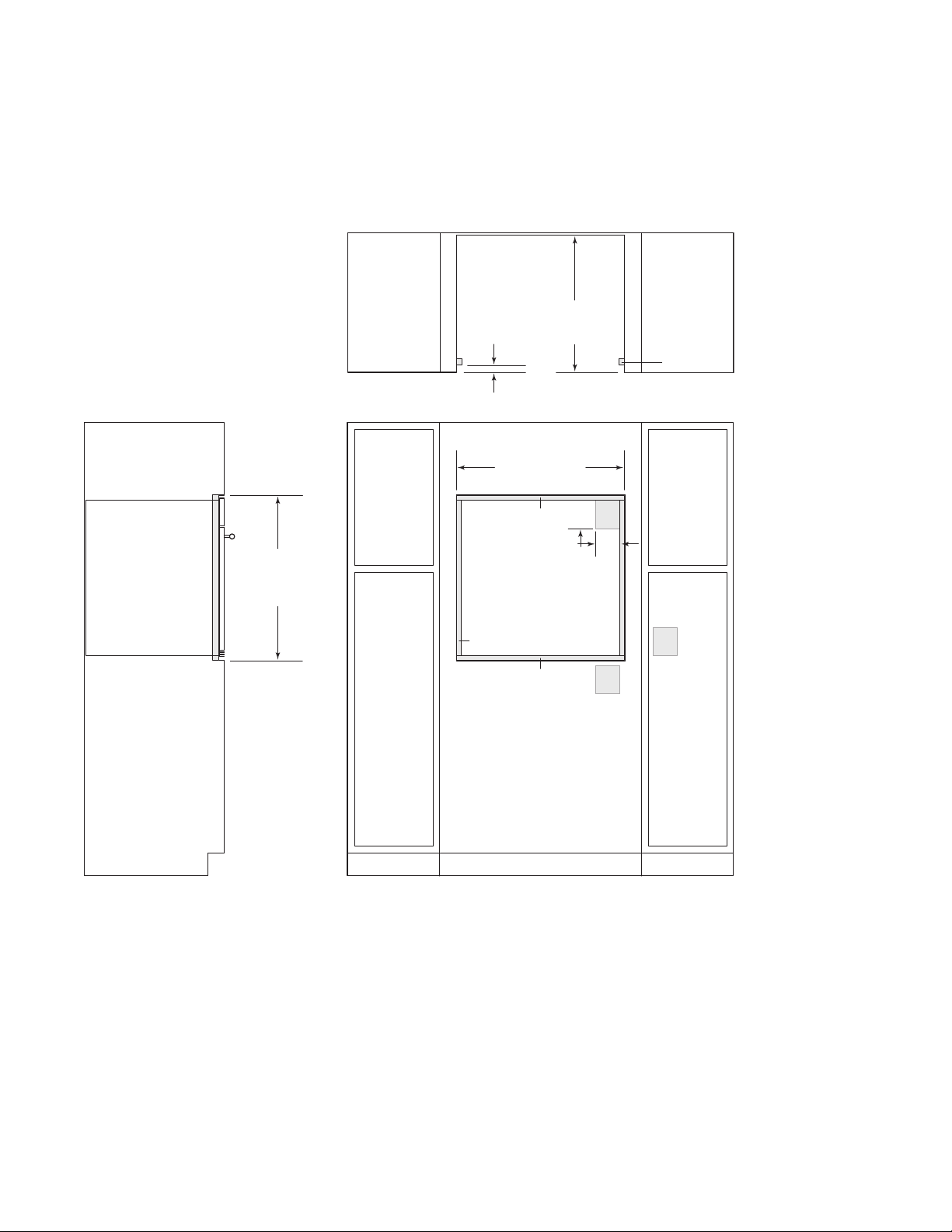
The oven can be installed in a standard or flush inset
application. If a cooktop is installed above an oven, a
minimum of 1/4" (6) is required between the units. The
location of the electrical supply within the oven opening
may require additional cabinet depth.
Bas e S u p port Min
Single Oven 250 lb (115 kg)
Double Oven 400 lb (181 kg)
Finish the edges of the opening. They may be visible
when the door is open.
For standard installations, the face trim overlaps stiles and
rails.
Tri m O v e rlap Dim e n s i o n
Top 1" (25)
Bottom 0"
Sides
11
/16" (18)
Dual Installation
Two 30" single ovens can be installed side by side in a
standard or flush inset application. A dual installation kit is
required. To maintain appropriate airflow, the ovens must
be installed into one opening. Any cosmetic or structural
material placed between the ovens will impede airflow
and is not recommended. Refer to the illustrations on the
following pages.
The dual installation kit is available through an authorized
Wolf dealer. For local dealer information, visit the locator
section of our website subzero-wolf.com.
For flush inset installations, a minimum 1/8" (3) reveal is
required on all sides. To ensure consistent reveals, each
corner of the opening must be exactly 90°.
4 | English
Page 5

Specifications
Electrical Requirements
Electrical Requirements
Installation must comply with all applicable electrical
codes.
Locate the electrical supply flush with the back wall and
within the shaded area shown in the illustrations on pages
6-11. For ease of installation, the electrical supply for the
oven can be placed in an adjacent cabinet within reach of
the conduit.
Performance may be compromised if the electrical supply
is less than 240 volts.
The oven is supplied with a conduit consisting of two
insulated hot lead conductors and a bare ground
conductor. The wiring diagram covering the control
circuit is provided with the oven.
ELE C T R I C AL REQUIR E M E N T S-Single O v e n
Electrical Supply
Service 30 amp dedicated circuit
Conduit 4' (1.2 m)
Total Amps 22
Max Connected Load 5.4 kW
ELE C T R I C AL REQUIR E M E N T S-Double O v e n
Electrical Supply
Service 50 amp dedicated circuit
Conduit 5' (1.5 m)
Total Amps 45
Max Connected Load 10.8 kW
grounded, 240/208 VAC,
60Hz
grounded, 240/208 VAC,
60Hz
wolfappliance.com | 5
Page 6

281/2" (724)
OPENING WIDTH
E
5"
(127)
E
E
4"
(102)
FRONT VIEWSIDE VIEW
NOTE: Location of electrical supply within opening may require additional cabinet depth.
231/4" (591)
OPENING
DEPTH
TOP VIEW
271/2"
(699)
OPENING
HEIGHT
Specifications
30" Single Oven Standard
30" Single Oven Standard
Installation
Installation
6 | English
Page 7

301/8" (765)
FLUSH INSET WIDTH**
*Shaded areas will be visible and should be finished to match cabinetry.
**Dimension provides minimum reveals.
NOTE: Location of electrical supply within opening may require additional cabinet depth.
283/4"
(730)
FLUSH INSET
HEIGHT**
E
5"
(127)
4"
(102)
FRONT VIEWSIDE VIEW
11/8" (29)
1
/8" (3)
13
/16" (21)
24" (610)
FLUSH INSET
DEPTH
7
/8" (22)
TOP VIEW
E
E
FINISHED
CLEATS*
Specifications
30" Single Oven Flush Inset
30" Single Oven Flush Inset
Installation
Installation
wolfappliance.com | 7
Page 8

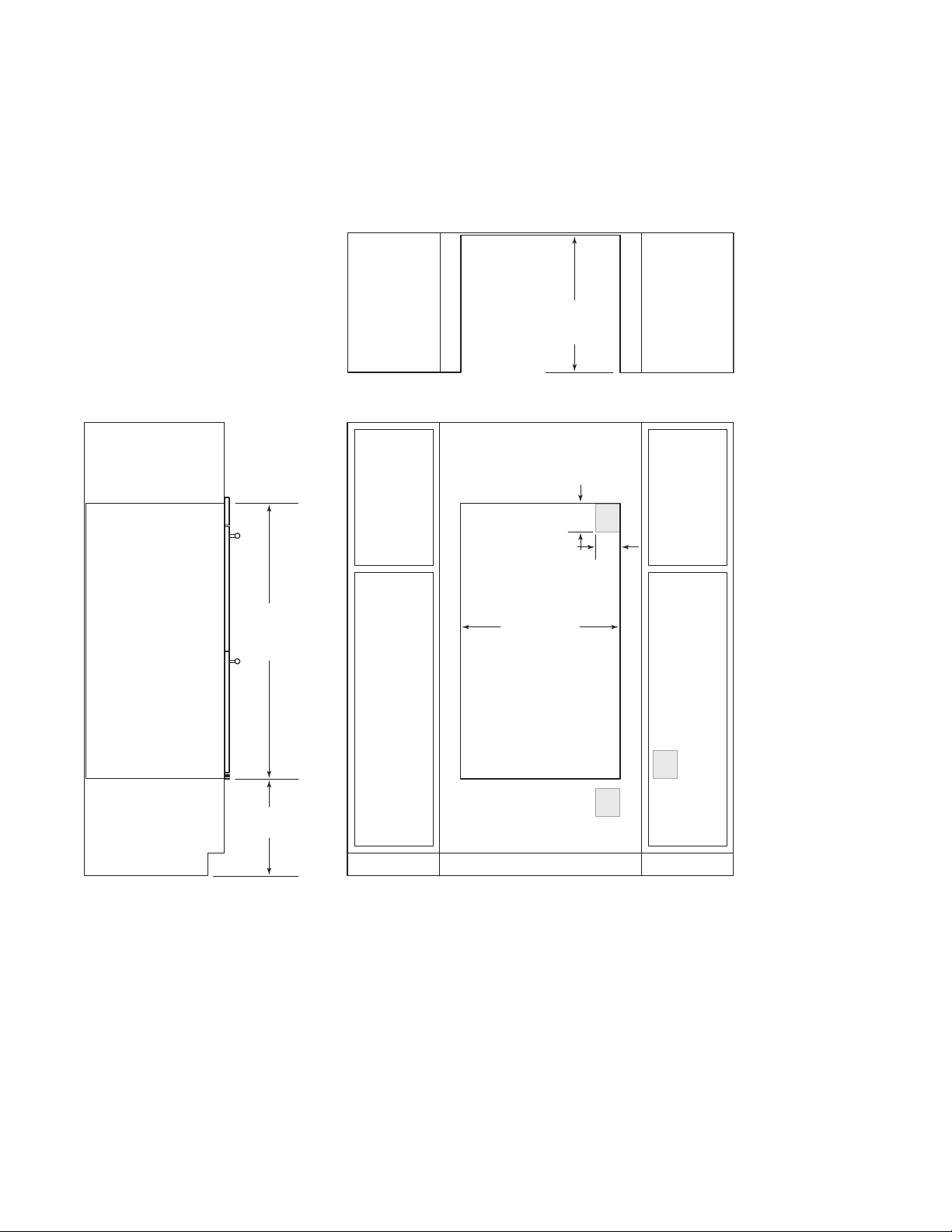
281/2" (724)
OPENING WIDTH
E
5"
(127)
4"
(102)
E
E
FRONT VIEWSIDE VIEW
NOTE: Location of electrical supply within opening may require additional cabinet depth.
497/8"
(1267)
OPENING
HEIGHT
231/4" (591)
OPENING
DEPTH
17" (432)
TYPICAL
TOP VIEW
Specifications
30" Double Oven Standard
30" Double Oven Standard
Installation
Installation
8 | English
Page 9

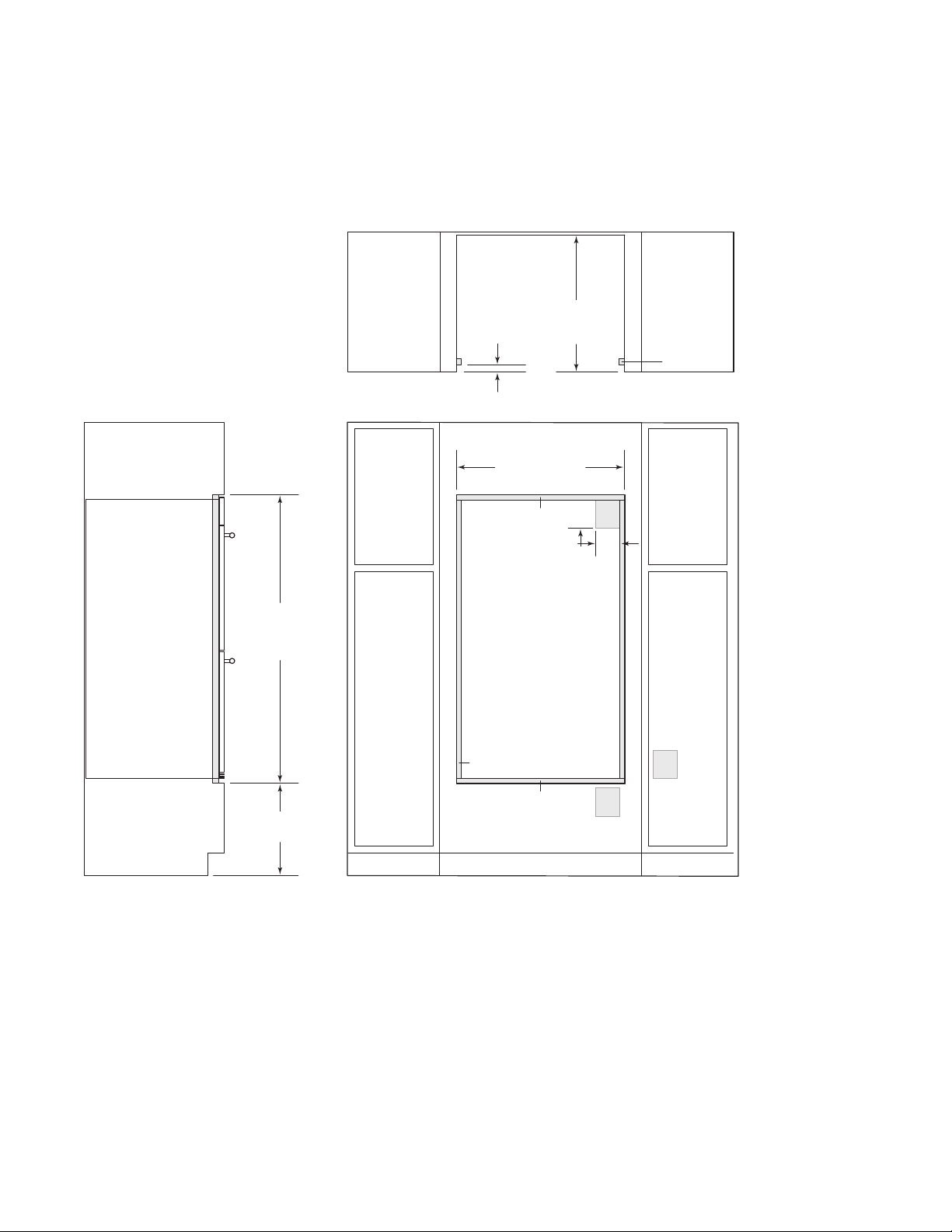
301/8" (765)
FLUSH INSET WIDTH**
E
5"
(127)
4"
(102)
FRONT VIEWSIDE VIEW
511/8"
(1299)
FLUSH INSET
HEIGHT**
11/8" (29)
1
/8" (3)
13
/16" (21)
24" (610)
FLUSH INSET
DEPTH
17" (432)
TYPICAL
TOP VIEW
E
E
FINISHED
CLEATS*
*Shaded areas will be visible and should be finished to match cabinetry.
**Dimension provides minimum reveals.
NOTE: Location of electrical supply within opening may require additional cabinet depth.
7
/8" (22)
Specifications
30" Double Oven Flush
30" Double Oven Flush
Inset Installation
Inset Installation
wolfappliance.com | 9
Page 10

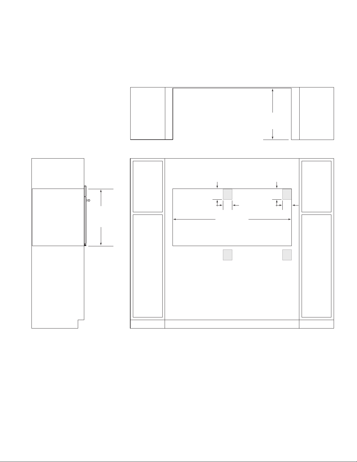
E
5"
(127)
E E
4"
(102)
E
5"
(127)
4"
(102)
FRONT VIEWSIDE VIEW
NOTE: Location of electrical supply within opening may require additional cabinet depth. A dual installation kit is required for this installation.
231/4" (591)
OPENING
DEPTH
TOP VIEW
271/2"
(699)
OPENING
HEIGHT
581/2" (1486)
OPENING WIDTH
Specifications
30" Single Oven Dual
30" Single Oven Dual
Standard Installation
Standard Installation
10 | English
Page 11

E
5"
(127)
4"
(102)
E
5"
(127)
4"
(102)
FRONT VIEWSIDE VIEW
*1" (25) minimum depth. Shaded areas will be visible and should be finished to match cabinetry.
**Dimension provides minimum reveals.
NOTE: Location of electrical supply within opening may require additional cabinet depth. A dual installation kit is required for this installation.
283/4"
(730)
FLUSH INSET
HEIGHT**
11/8" (29)
1
/8" (3)
13
/16" (21)
24" (610)
FLUSH INSET
DEPTH
7
/8" (22)
601/8" (1527)
FLUSH INSET WIDTH**
TOP VIEW
EE
FINISHED
CLEATS*
Specifications
30" Single Oven Dual Flush
30" Single Oven Dual Flush
Inset Installation
Inset Installation
wolfappliance.com | 11
Page 12

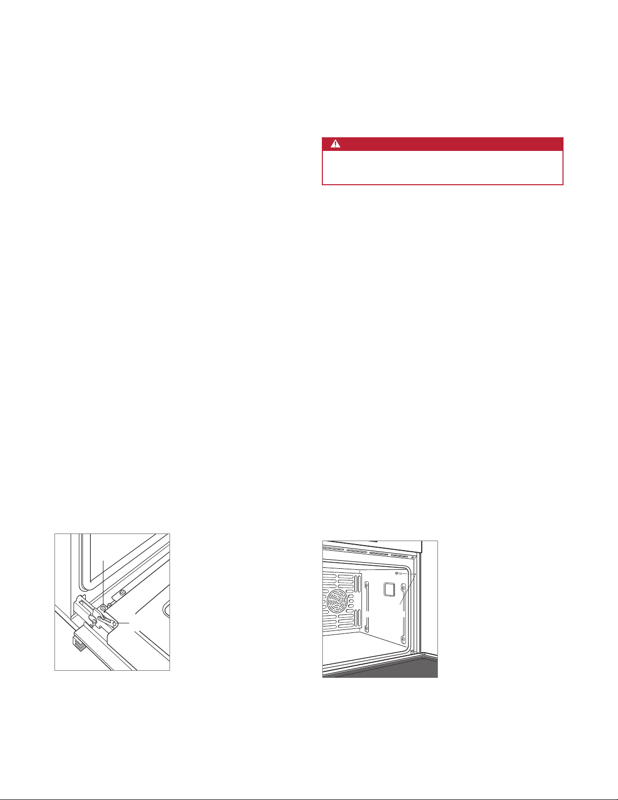
HINGE
LOCK
SCREW
Installation
Preparation
Preparation
Electrical Connection
Before moving the oven, protect any finished flooring and
secure the oven door(s) closed to prevent damage.
Use an appliance dolly to move the oven near the
opening. Place the appliance dolly on the side or back to
prevent damage. Remove and recycle packing materials.
Do not lift or carry the oven by the door handle.
Oven Door Removal
To lighten the load, the oven door(s) can be removed.
Remove only if necessary. Door removal should be done
only by a certified installer or service technician. Do not
lift or carry the oven door by the door handle.
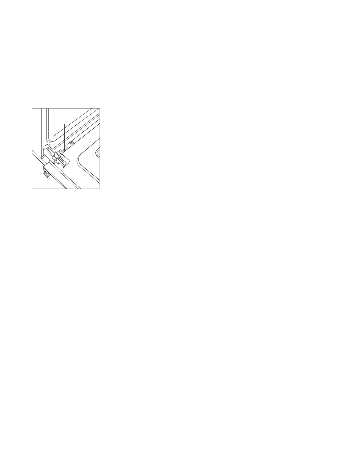
To remove, open the door completely. Rotate both hinge
locks back completely, remove the screw closest to the
hinge on both sides of the door, and pull the door
forward.
To install, slide the door onto the hinges. Rotate the hinge
locks forward completely and install the screws.
WARNING
Verify that power is disconnected from the electrical
box before proceeding.
If the electrical supply is located in the opening, electrical
connection must be made prior to placing the oven in the
opening. If the electrical supply is in an adjacent cabinet,
electrical connection can be made after placing the oven
in the opening. The conduit on the back of the unit allows
for a 3-wire or 4-wire installation.
1
Connect the black appliance wire to the black (L1)
power supply.
2
Connect the red appliance wire to the red (L2) power
supply.
3
Connect the bare appliance wire to the green/ground
wire.
4
For a four-wire system, install a wire nut on the white/
neurtral wire.
Installation
Place the oven in the opening and slide into position. To
ensure adequate depth for proper installation, the conduit
must fit into the recessed area along the rear edge of the
oven.
Locate the mounting hole in each side trim. Drill 1/16" (2)
pilot holes and install #6 x 3/4" screws.
Remove and recycle packing materials including the
white protective material behind each rack guide
mounting location.
12 | English
Page 13
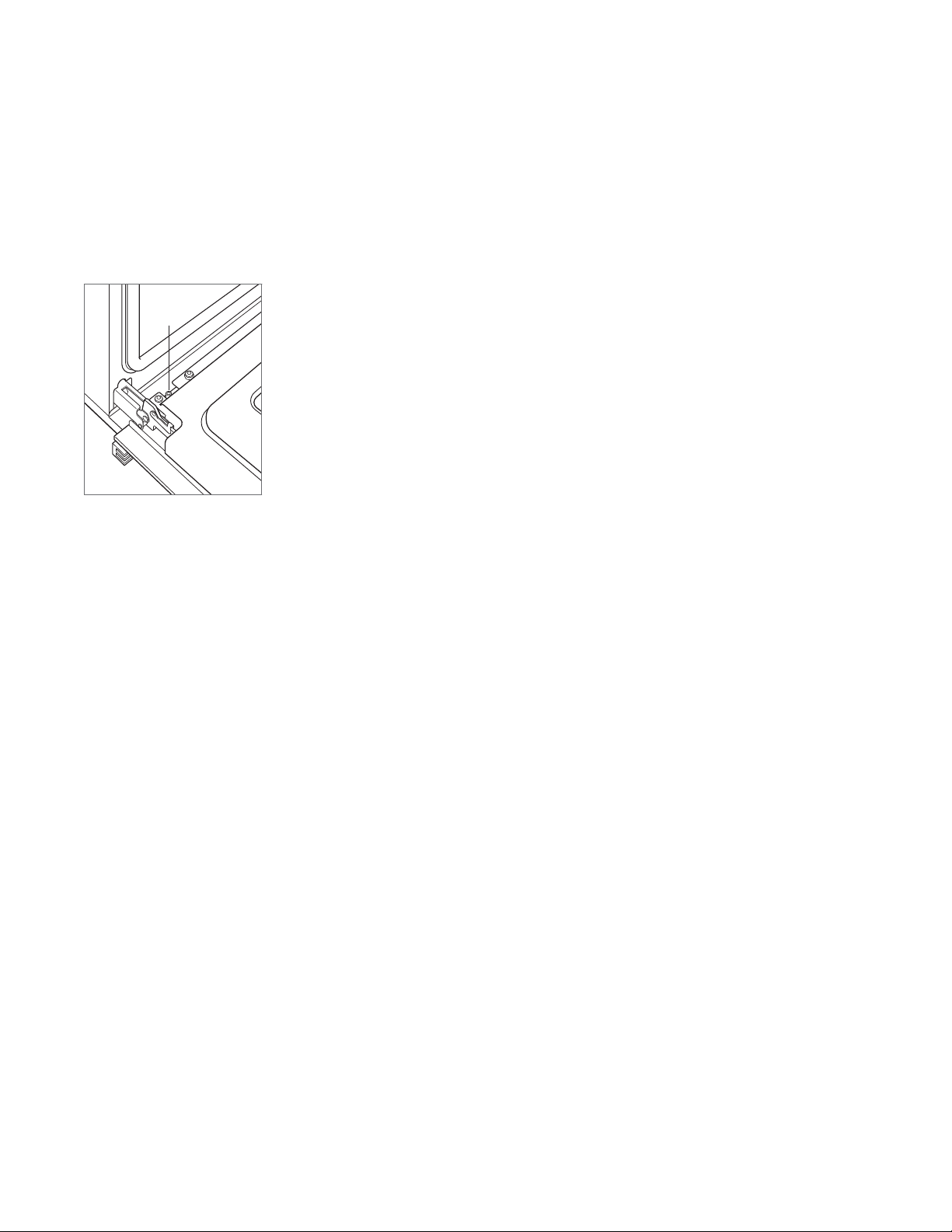
NUT
Installation
Door Alignment
Door Alignment
To adjust the door, loosen the nuts on both sides of the
door, manually adjust the bottom of the door side to side,
and tighten the nuts.
Troubleshooting
IMPORTANT NOTE: If the range does not operate properly,
follow these troubleshooting steps:
• Verify electrical power is supplied to the oven.
• Verify proper electrical connections.
• If the oven does not operate properly, contact Wolf
Factory Certified Service. Do not attempt to repair the
oven. Wolf is not responsible for service required to
correct a faulty installation.
wolfappliance.com | 13
Page 14
Horno de la serie E
Horno de la serie E
Contenido
Aviso importante
14
Información del producto
15
Especificaciones
16
Instalación
24
Aviso importante
Para asegurarse de que este producto se instale y opere
de forma segura y eficiente, tome nota de los siguientes
tipos de información resaltada en este manual:
NOTA IMPORTANTE:: Señala la información que es
especialmente importante.
PRECAUCIÓN
Indica una situación en la que se pueden sufrir
lesiones leves o provocar daños al producto, si no se
siguen las instrucciones.
ADVERTENCIA
Indica peligro de que se produzcan heridas graves o
incluso la muerte si no se siguen las precauciones.
NOTA IMPORTANTE:: En toda esta guía, las dimensiones
entre paréntesis son milímetros, a menos que se
especifique lo contrario.
14 | Español
Page 15

Horno de la serie E
Información del producto
Información del producto
La información importante del producto, incluidos el
modelo y el número de serie de la unidad, se encuentra
en la placa de datos del producto. Si es necesario realizar
algún servicio, póngase en contacto con el servicio
certificado de fábrica de Wolf y tenga a mano el número
de modelo y el número de serie. Para obtener los datos
del centro de servicio certificado de fábrica de Wolf más
cercano o si tiene preguntas acerca de la instalación,
visite la sección de soporte del producto en nuestra
página de Internet o llame a la línea de atención al cliente
de Wolf al 800-222-7820.
La placa de datos se encuentra cerca de la moldura
inferior en la izquierda. La puerta del horno debe estar
abierta para ver la placa de datos.
wolfappliance.com | 15
Page 16

Especificaciones
Requisitos de instalación
Requisitos de instalación
El horno se puede instalar en una aplicación estándar o
empotrable. Si se instala una estufa sobre un horno, se
requiere un espacio mínimo de 1/4" (6) entre las unidades.
Es posible que la ubicación del suministro eléctrico al
interior de la abertura del horno requiera de un gabinete
de mayor profundidad.
Sop o r t e de la bas e Mín
Horno sencillo 250 lb (115 kg)
Horno doble 400 lb (181 kg)
Dé el acabado a los bordes de la abertura. Pueden ser
visibles cuando la puerta está abierta.
Para instalaciones estándar, el ribete frontal se superpone
a los largueros y las guías.
Sup e r p o s ición del r i b e te Dim e n s i ó n
Parte superior 1" (25)
Parte inferior 0" (76.2 cm)
Laterales
11
/16" (18)
Instalación doble
Se pueden instalar dos hornos sencillos de 30”, uno al
lado del otro, en una aplicación estándar o empotrable.
Se requiere kit de instalación doble. Para mantener un
flujo de aire adecuado, los hornos se deben instalar en
una sola abertura. Cualquier elemento cosmético o
estructural que se coloque entre los hornos obstruirá el
flujo de aire y, por lo tanto, no se recomienda. Consulte
las ilustraciones de las páginas siguientes.
El kit de instalación doble está disponible a través de un
distribuidor autorizado de Wolf. Para obtener más
información acerca de los distribuidores locales, consulte
la sección de ubicador en nuestra página web subzero-
wolf.com.
Para las instalaciones empotrables se requiere un margen
mínimo de 1/8" (3) en todos los lados. Para asegurar
márgenes consistentes, cada esquina de la abertura debe
tener exactamente 90º.
16 | Español
Page 17

Especificaciones
Requisitos eléctricos
Requisitos eléctricos
REQ U I S I T OS ELÉCTR I C O S - Horno s e n c i l lo
Suministro eléctrico
Con conexión a tierra,
240/208 V CA, 60Hz
Servicio
Conducto 4' (1.2 m)
Total de amperes 22
Carga máxima conectada 5.4 kW
REQ U I S I T OS ELÉCTR I C O S - Horno d o b l e
Suministro eléctrico
Servicio
Conducto 5' (1.5 m)
Total de amperes 45
Carga máxima conectada 10.8 kW
Circuito dedicado de 30
amperes
Con conexión a tierra,
240/208 V CA, 60Hz
Circuito dedicado de 50
amperes
wolfappliance.com | 17
Page 18
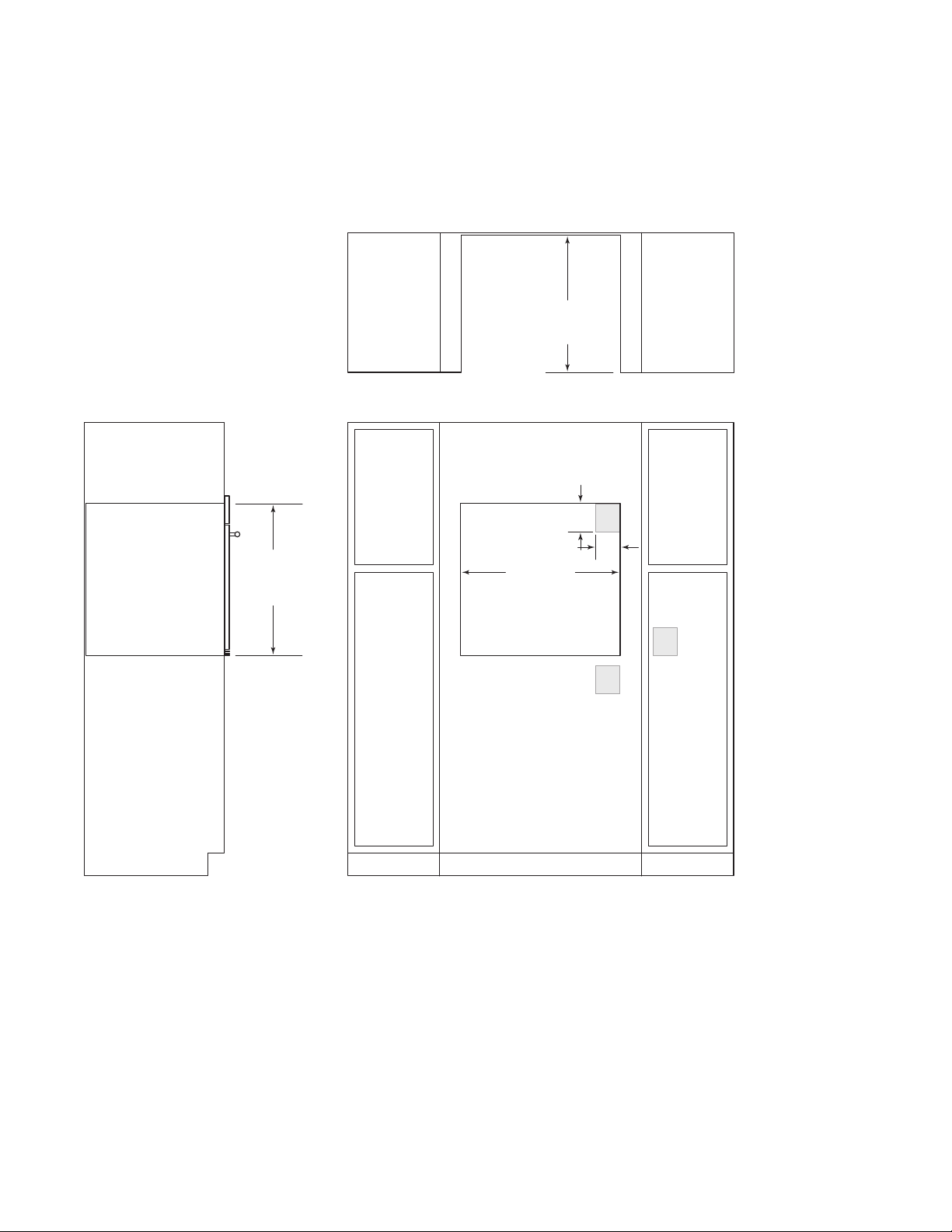
281/2" (724)
ANCHO DE LA ABERTURA
E
5"
(127)
E
E
4"
(102)
VISTA FRONTALVISTA LATERAL
NOTA: es posible que la ubicación del suministro eléctrico al interior de la abertura requiera de un gabinete de mayor profundidad.
231/4" (591)
PROFUNDIDAD DE
LA ABERTURA
VISTA SUPERIOR
271/2"
(699)
ALTURA DE
LA ABERTURA
Especificaciones
Instalación estándar de
Instalación estándar de
horno sencillo de 30”
horno sencillo de 30”
18 | Español
Page 19
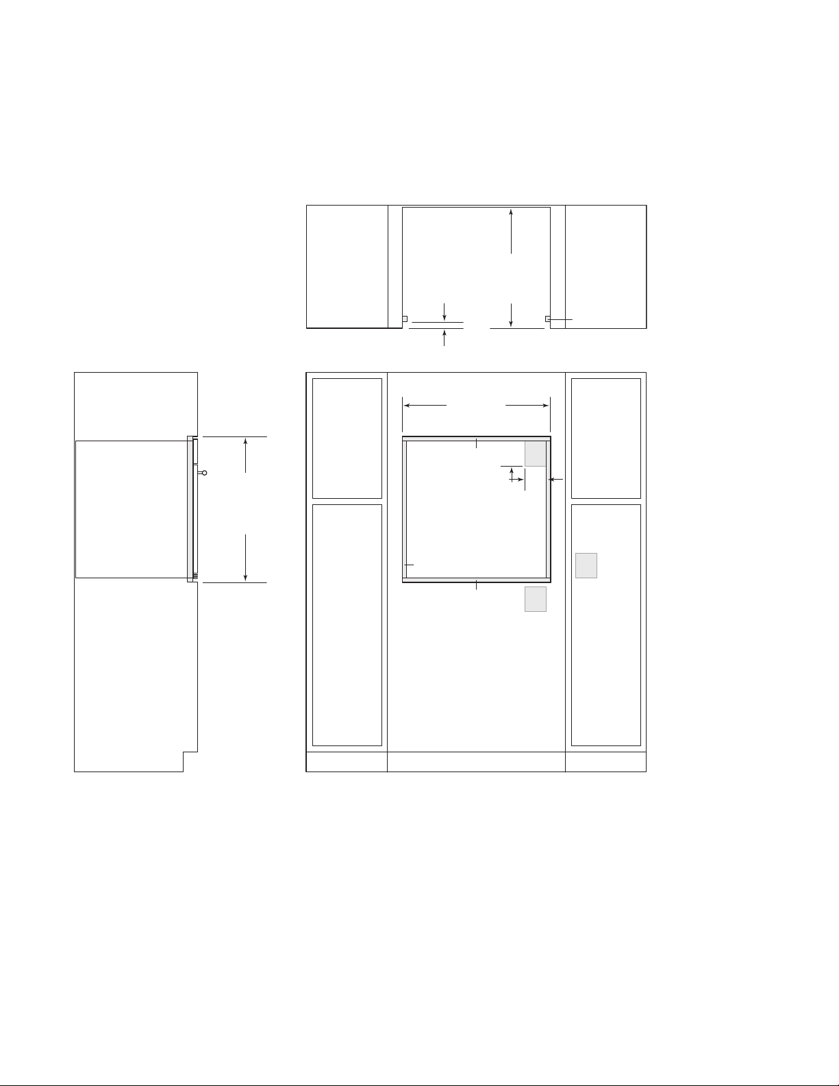
*Las áreas sombreadas serán visibles y se les debe dar un acabado que combine con los gabinetes.
**La dimensión especifica los márgenes mínimos.
NOTA: es posible que la ubicación del suministro eléctrico al interior de la abertura requiera de un gabinete de mayor profundidad.
283/4"
(730)
ALTURA DE
LA INSTALACIÓN
EMPOTRABLE**
E
5"
(127)
4"
(102)
11/8" (29)
1
/8" (3)
13
/16" (21)
24" (610)
PROFUNDIDAD DE
LA INSTALACIÓN
EMPOTRABLE
7
/8" (22)
E
E
CORNAMUSAS
TERMINADAS*
301/8" (765)
ANCHO DE LA
INSTALACIÓN EMPOTRABLE**
VISTA FRONTALVISTA LATERAL
VISTA SUPERIOR
Especificaciones
Instalación empotrable de
Instalación empotrable de
horno sencillo de 30”
horno sencillo de 30”
wolfappliance.com | 19
Page 20
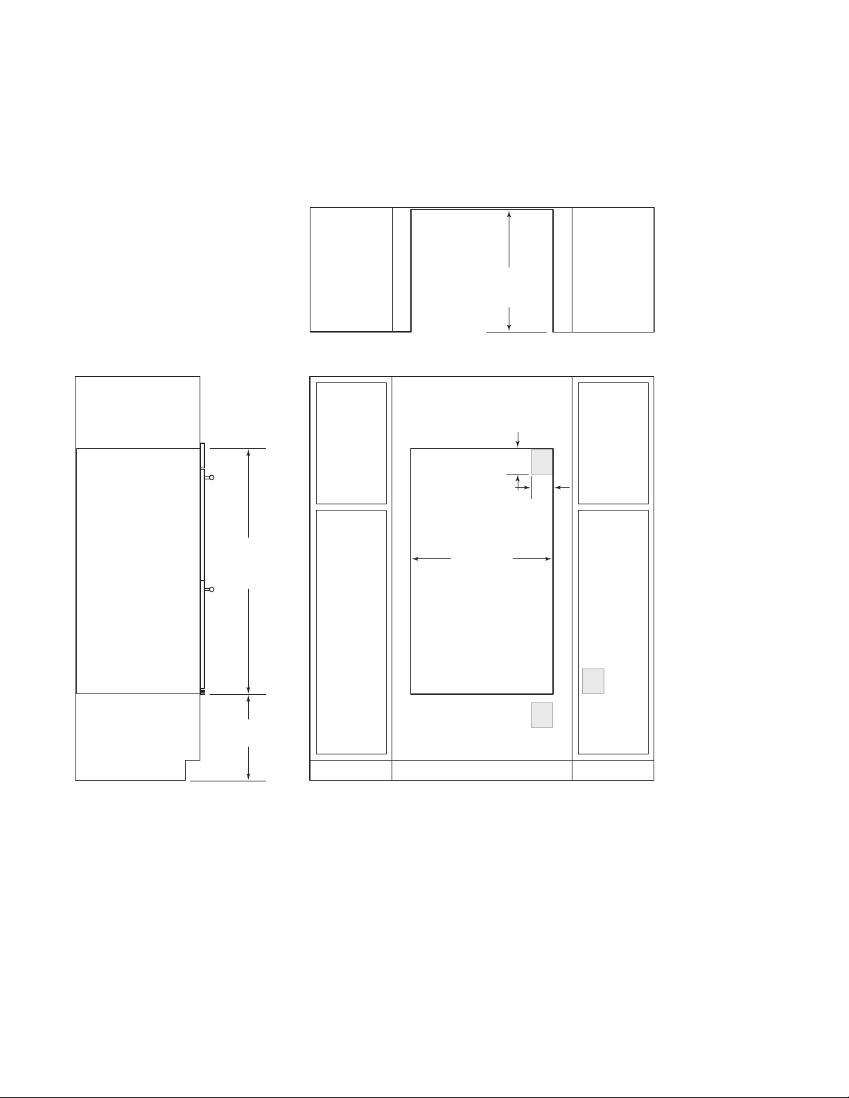
281/2" (724)
ANCHO DE LA ABERTURA
E
5"
(127)
4"
(102)
E
E
VISTA FRONTALVISTA LATERAL
NOTA: es posible que la ubicación del suministro eléctrico al interior de la abertura requiera de un gabinete de mayor profundidad.
497/8"
(1267)
ALTURA DE
LA ABERTURA
231/4" (591)
PROFUNDIDAD DE
LA ABERTURA
17" (432)
TÍPICO
VISTA SUPERIOR
Especificaciones
Instalación estándar de
Instalación estándar de
horno doble de 30”
horno doble de 30”
20 | Español
Page 21
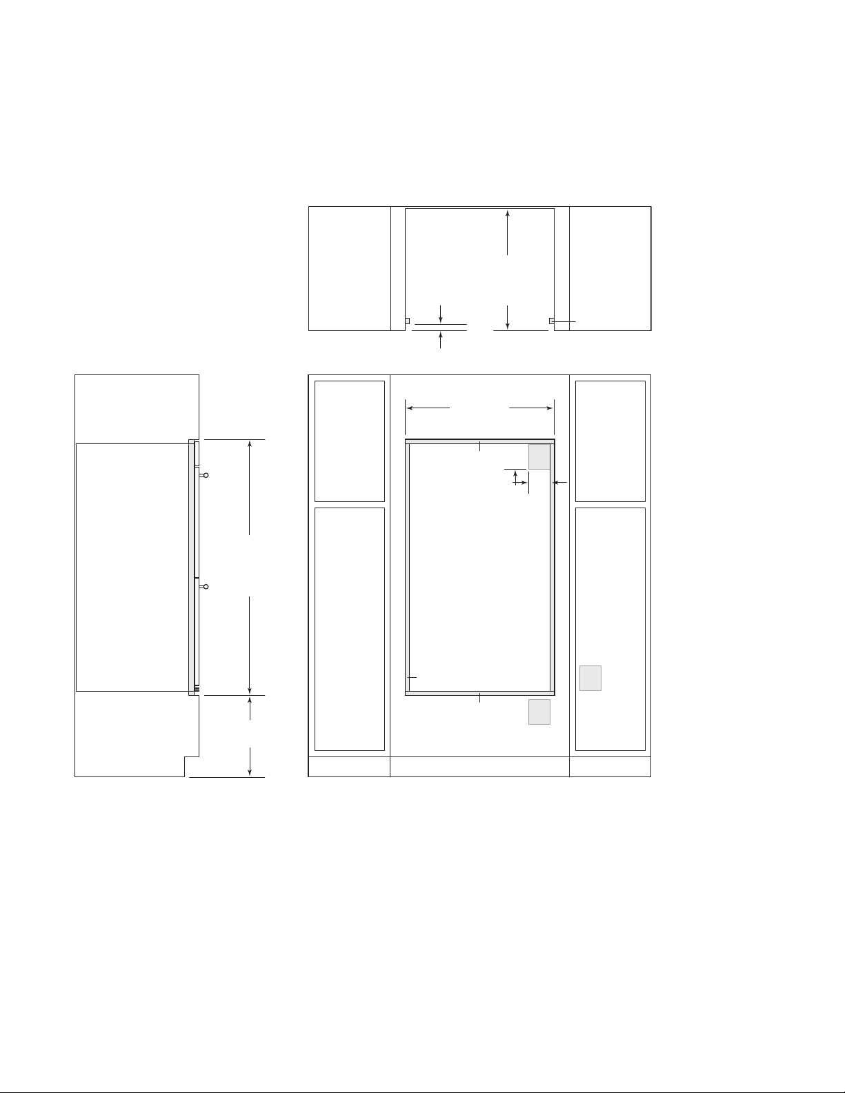
301/8" (765)
ANCHO DE LA
INSTALACIÓN EMPOTRABLE**
E
5"
(127)
4"
(102)
VISTA FRONTALVISTA LATERAL
511/8"
(1299)
ALTURA DE
LA INSTALACIÓN
EMPOTRABLE**
11/8" (29)
1
/8" (3)
13
/16" (21)
24" (610)
PROFUNDIDAD DE
LA INSTALACIÓN
EMPOTRABLE
17" (432)
TÍPICO
VISTA SUPERIOR
E
E
CORNAMUSAS
TERMINADAS*
*Las áreas sombreadas serán visibles y se les debe dar un acabado que combine con los gabinetes.
**La dimensión especifica los márgenes mínimos.
NOTA: es posible que la ubicación del suministro eléctrico al interior de la abertura requiera de un gabinete de mayor profundidad.
7
/8" (22)
Especificaciones
Instalación empotrable de
Instalación empotrable de
horno doble de 30”
horno doble de 30”
wolfappliance.com | 21
Page 22
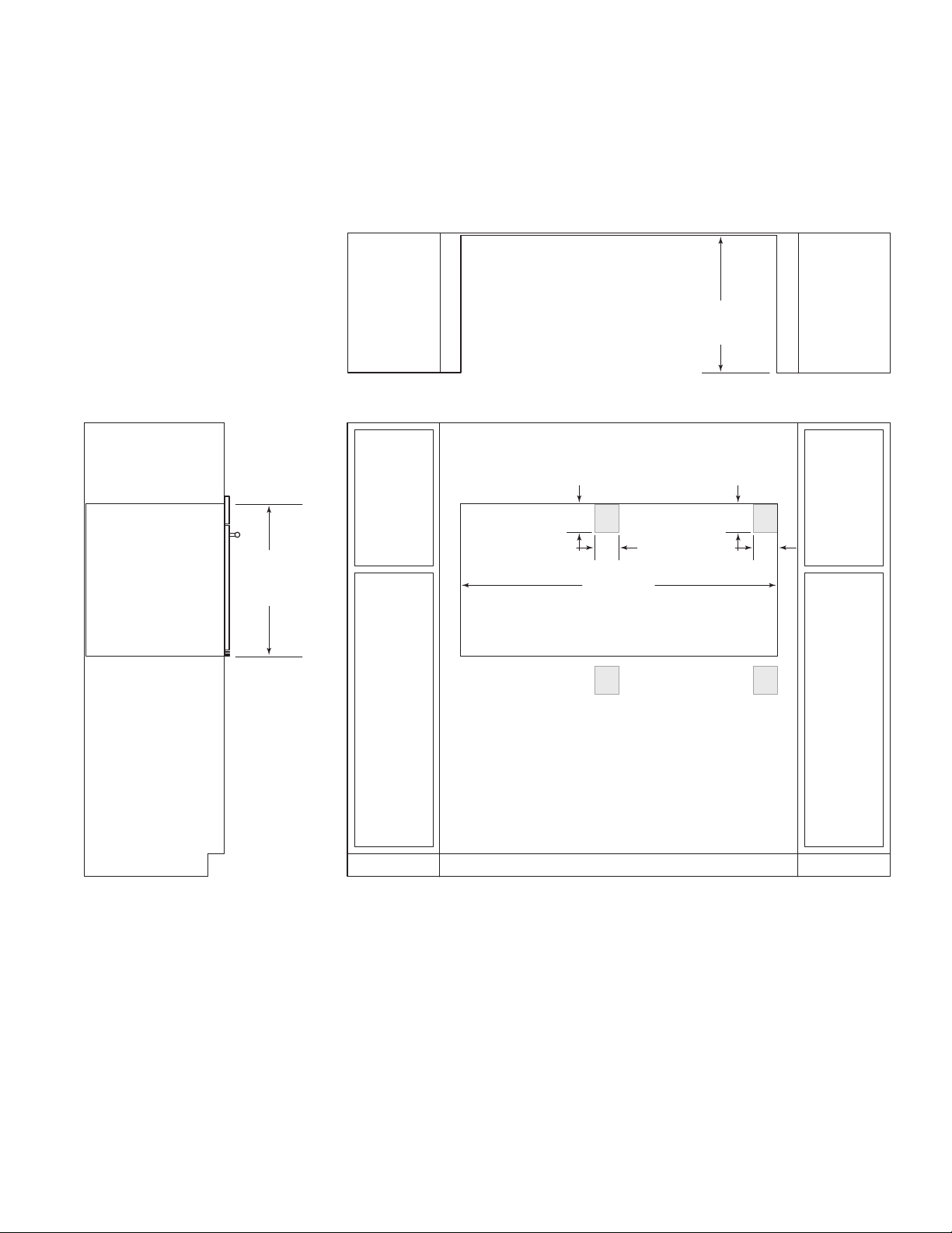
E
5"
(127)
E E
4"
(102)
E
5"
(127)
4"
(102)
VISTA FRONTALVISTA LATERAL
NOTA: es posible que la ubicación del suministro eléctrico al interior de la abertura requiera de un gabinete de mayor profundidad.
Para esta instalación se requiere un kit de instalación doble.
231/4" (591)
PROFUNDIDAD DE
LA ABERTURA
VISTA SUPERIOR
271/2"
(699)
ALTURA DE
LA ABERTURA
581/2" (1486)
ANCHO DE LA ABERTURA
Especificaciones
Instalación dual estándar de
Instalación dual estándar de
horno sencillo de 30”
horno sencillo de 30”
22 | Español
Page 23
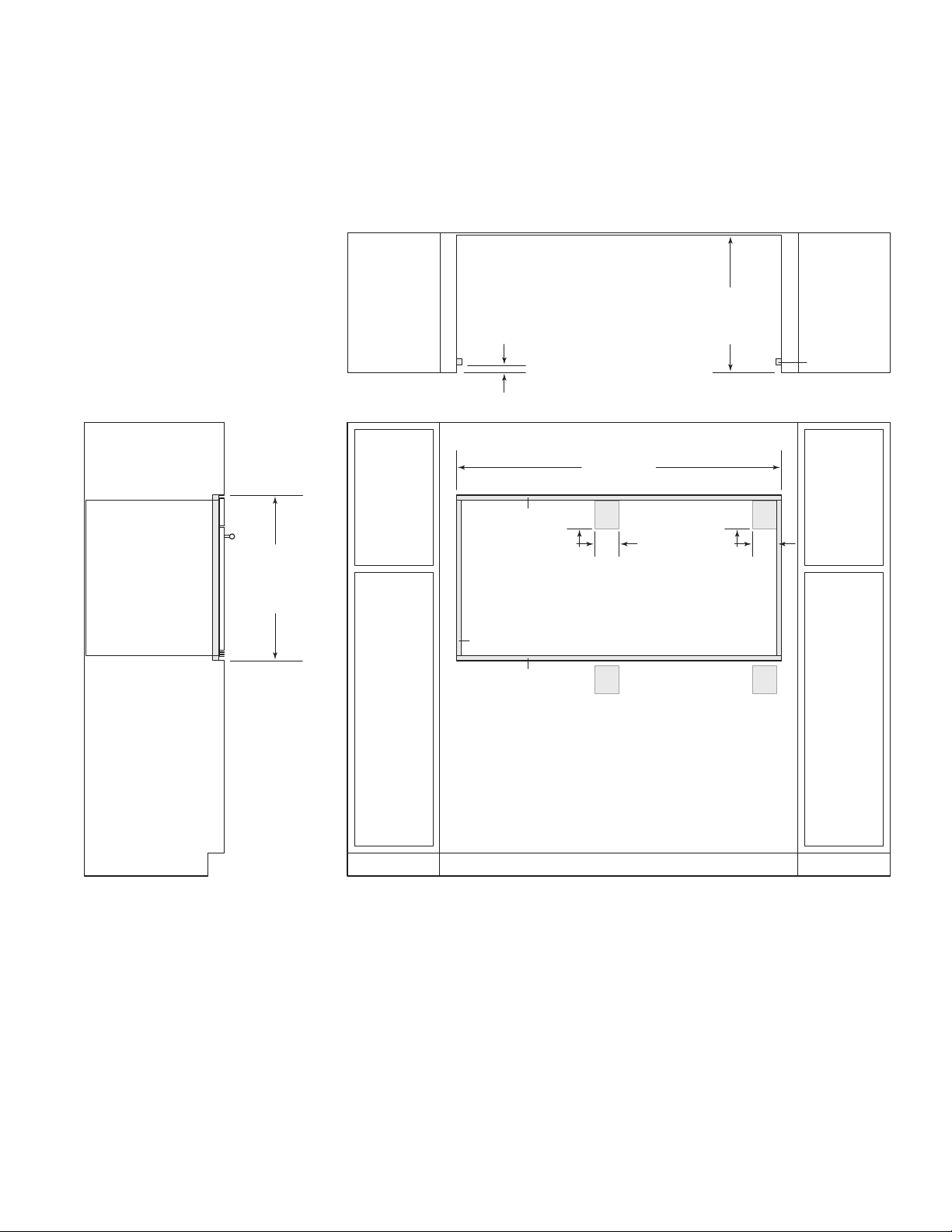
E
5"
(127)
4"
(102)
E
5"
(127)
4"
(102)
VISTA FRONTALVISTA LATERAL
*1" (25) profundidad mínima. Las áreas sombreadas serán visibles y se les debe dar un acabado que combine con los gabinetes.
**La dimensión especifica los márgenes mínimos.
NOTA: es posible que la ubicación del suministro eléctrico al interior de la abertura requiera de un gabinete de mayor profundidad.
Para esta instalación se requiere un kit de instalación doble.
283/4"
(730)
ALTURA DE
LA INSTALACIÓN
EMPOTRABLE**
11/8" (29)
1
/8" (3)
13
/16" (21)
24" (610)
PROFUNDIDAD DE
LA INSTALACIÓN
EMPOTRABLE
7
/8" (22)
601/8" (1527)
ANCHO DE LA INSTALACIÓN EMPOTRABLE**
VISTA SUPERIOR
EE
CORNAMUSAS
TERMINADAS*
Especificaciones
Instalación dual empotrable
Instalación dual empotrable
de horno sencillo de 30”
de horno sencillo de 30”
wolfappliance.com | 23
Page 24
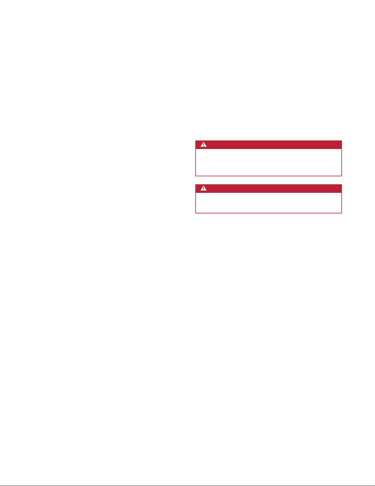
TORNILLO
BLOQUEO
DE BISAGRA
ORIFICIO
DE MONTAJE
Instalación
Preparación
Preparación
Conexión eléctrica
Antes de mover el horno, proteja cualquier suelo acabado
y asegúrese de que la puerta o puertas del horno estén
cerradas para que no se dañen.
Use una plataforma móvil para mover el horno cerca de la
abertura. Para evitar daños, coloque la carretilla del
electrodoméstico en el costado o en la parte posterior.
Retire y recicle los materiales de embalaje. No utilice la
manija de la puerta del horno para levantarlo ni
transportarlo.
Cómo quitar la puerta del
horno
Para aligerar la carga, puede quitarse la puerta o puertas
del horno. Solo deberá quitarse si es necesario. El
proceso para quitar la puerta del horno debe ser realizado
solamente por un instalador certificado o un técnico de
servicio. No utilice la manija de la puerta del horno para
levantar la puerta ni para transportarla.
Para quitarla, abra la puerta completamente. Gire los
pestillos de las dos bisagras hacia atrás completamente,
quite el tornillo más cercano a la bisagra en ambos lados
de la puerta, y a continuación jale la puerta hacia delante.
Para instalar, deslice la puerta en las bisagras. Gire los
pestillos de las bisagras completamente hacia adelante e
instale los tornillos.
ADVERTENCIA
Verifique que la alimentación esté desconectada de
la caja eléctrica antes de proceder.
Si el suministro eléctrico se ubica en la abertura, la
conexión eléctrica debe hacerse antes de colocar el
horno en la abertura. Si el suministro eléctrico está en un
gabinete anexo, la conexión eléctrica puede hacerse
después de colocar el horno en la abertura. El conducto
en la parte posterior de la unidad permite una instalación
de 3 cables o 4 cables.
1
Conecte el cable negro del electrodoméstico al cable
negro (L1) del suministro eléctrico.
2
Conecte el cable rojo del electrodoméstico al cable
rojo (L2) del suministro eléctrico.
3
Conecte el cable desnudo del electrodoméstico al
cable verde/ tierra.
4
Para un sistema de cuatro cables, instale una tuerca
de cable en el cable blanco/neutral.
Installation
Place the oven in the opening and slide into position. To
ensure adequate depth for proper installation, the conduit
must fit into the recessed area along the rear edge of the
oven.
Locate the mounting hole in each side trim. Drill 1/16" (2)
pilot holes and install #6 x 3/4" screws.
24 | Español
Remove and recycle packing materials including the
white protective material behind each rack guide
mounting location.
Page 25
TUERCA
Instalación
Alineamiento de la puerta
Alineamiento de la puerta
Para ajustar la puerta, afloje las tuercas en ambos lados de
la puerta, ajuste manualmente la parte inferior de la
puerta de lado a lado, y apriete las tuercas.
Solución de problemas
NOTA IMPORTANTE:: Si la estufa no funciona
correctamente, siga estos pasos para resolver los
problemas:
• Compruebe que el horno tenga corriente eléctrica.
• Compruebe que las conexiones eléctricas estén
correctas.
• Si el horno no funciona correctamente, póngase en
contacto con el centro de servicio autorizado de Wolf.
No intente reparar el horno. Wolf no es responsable
del servicio necesario para corregir una instalación
defectuosa.
wolfappliance.com | 25
Page 26
Four de la série E
Four de la série E
Table des matières
Remarque importante
26
Renseignements sur le produit
27
Spécifications
28
Installation
36
Remarque importante
Pour s'assurer que ce produit est installé et utilisé en toute
sécurité et aussi efficacement que possible, prenez note
des types de renseignement mis en évidence tout au long
de ce guide :
REMARQUE IMPORTANTE: Met en évidence des
renseignements qui sont particulièrement importants.
MISE EN GARDE
Indique une situation où une blessure mineure ou
des dommages au produit peuvent se produire si les
directives ne sont pas respectées.
AVERTISSEMENT
Décrit un danger qui peut causer une blessure grave
ou la mort si les précautions ne sont pas respectées.
REMARQUE IMPORTANTE: Tout au long de ce guide, les
dimensions entre parenthèses sont en millimètres à
moins d’indication contraire.
26 | Français
Page 27

Four de la série E
Renseignements sur le
Renseignements sur le
produit
produit
Des renseignements importants sur le produit, y compris
les numéros de modèle et de série, se trouvent sur la
plaque signalétique du produit. Si vous avez besoin de
service, communiquez avec le service Wolf certifié par
l’usine avec les numéros de modèle et de série. Pour
obtenir le nom du centre de service Wolf certifié par
l’usine le plus près de chez vous ou si vous avez des
questions concernant l’installation, consultez la section
Support technique de notre site Web, ou appelez le
service à la clientèle de Wolf au 800-222-7820.
La plaque signalétique est située près de la garniture
inférieure du côté gauche. La porte du four doit être
ouverte pour voir la plaque signalétique.
wolfappliance.com | 27
Page 28

Spécifications
Exigences d’installation
Exigences d’installation
Le four peut être installé dans une application standard ou
à affleurement. Si la surface de cuisson est installée audessus d'un four, un espace minimum de 1/4 po (6) est
requis entre les unités. L'emplacement de l'alimentation
électrique dans l'ouverture du four peut exiger une
profondeur d'armoire supplémentaire.
Sup p o r t de base Min.
Four simple 250 lb (115 kg)
Four double 400 lb (181 kg)
Finissez les rebords de l'ouverture. Ils peuvent être visibles
lorsque la porte est ouverte.
Pour les installations standards, la garniture frontale
chevauchera les montants et les rails.
Che v a u c h ement de l a
gar n i t u r e
Dessus 1 po (25)
Bas 0 po (91,4 cm)
Côtés
Dim e n s i o ns
11
/16 po (18)
Installation double
Deux fours simples de 30 po peuvent être installés un à
côté de l'autre dans une application standard ou à
affleurement. Une trousse d'installation double est
requise. Pour préserver un débit d'air approprié, les fours
doivent être installés dans une seule ouverture. Tout
matériau cosmétique ou structurel placé entre les fours
empêchera le débit d'air et n'est pas recommandé.
Reportez-vous aux illustration sur les pages suivantes.
La trousse d'installation double est offerte par les
dépositaires Wolf autorisés. Pour obtenir des
renseignements sur votre dépositaire local, visitez la
section Localisateur de notre site Web subzero-wolf.com.
Pour les installations à affleurement, un jeu minimum
de 1/8 po (3) est requis de tous les côtés. Pour assurer des
jeux uniformes, chaque coin de l'ouverture doit mesurer
exactement 90 degrés.
28 | Français
Page 29

Spécifications
Exigences électriques
Exigences électriques
EXI G E N C E S ÉLECTRI Q U E S - four s i m p l e
Alimentation électrique
Service circuit dédié de 30 ampères
Canalisation 4 pi (1,2 m)
Intensité électrique 22 ampères
Charge max. de connexion 5,4 kW
EXI G E N C E S ÉLECTRI Q U E S - four d o u b l e
Alimentation électrique
mise à la terre, 240/208
volts CA, 60Hz
mise à la terre, 240/208
volts CA, 60 Hz
Service circuit dédié de 50 ampères
Canalisation 5 pi (1,5 m)
Intensité électrique 45 ampères
Charge max. de connexion 10,8 kW
wolfappliance.com | 29
Page 30
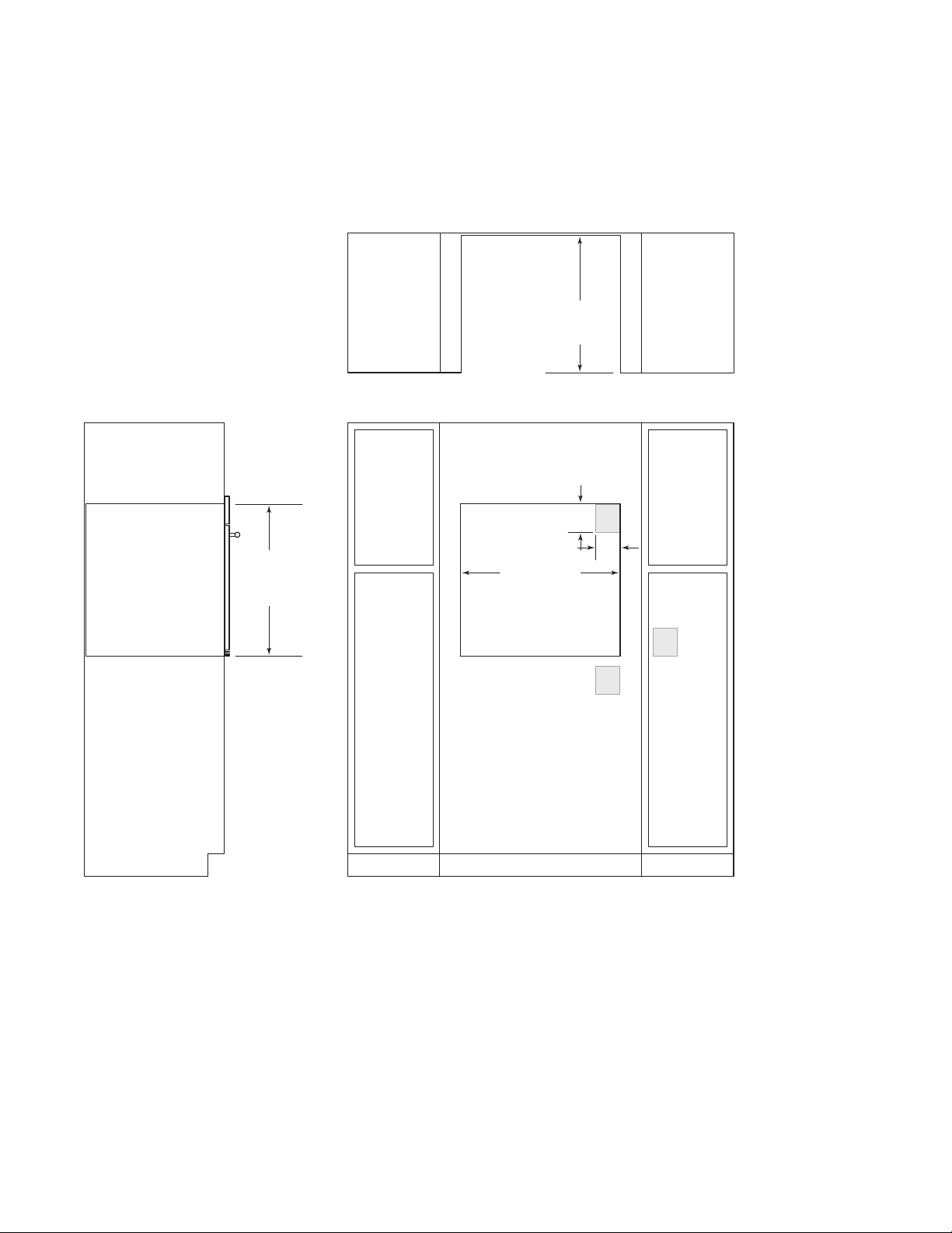
281/2 po (724)
LARGEUR DE L’OUVERTURE
E
5 po
(127)
E
E
4 po
(102)
VUE DE FACEVUE DE PROFIL
REMARQUE : L’emplacement de l’alimentation électrique dans l’ouverture peut exiger une profondeur d’armoire supplémentaire.
231/4 po (591)
PROFONDEUR
D’OUVERTURE
VUE DE DESSUS
271/2 po
(699)
HAUTEUR DE
L’OUVERTURE
Spécifications
Installation standard d'un
Installation standard d'un
four simple 30 po (762)
four simple 30 po (762)
30 | Français
Page 31
LARGEUR D’AFFLEUREMENT DE
301/8 po (765)**
*Les zones ombragées seront visibles et doivent être finies pour s’agencer avec les armoires.
**La dimension fournit des jeux minimums.
REMARQUE : L’emplacement de l’alimentation électrique dans l’ouverture peut exiger une profondeur d’armoire supplémentaire.
HAUTEUR
D’AFFLEUREMENT
DE 28
3
/4 po
(730)**
E
5 po
(127)
4 po
(102)
VUE DE FACEVUE DE PROFIL
11/8 po (29)
1
/8 po (3)
13
/16 po (21)
PROFONDEUR
D’AFFLEUREMENT
DE 24 po (610)
7
/8 po (22)
VUE DE DESSUS
E
E
TAQUETS
FINIS*
Spécifications
Installation à affleurement
Installation à affleurement
d'un four simple 30 po (762)
d'un four simple 30 po (762)
wolfappliance.com | 31
Page 32
LARGEUR DE L’OUVERTURE DE
281/2 po (724)
E
5 po
(127)
4 po
(102)
E
E
VUE DE FACEVUE DE PROFIL
REMARQUE : L’emplacement de l’alimentation électrique dans l’ouverture peut exiger une profondeur d’armoire supplémentaire.
HAUTEUR DE
L’OUVERTURE
DE 49
7
/8 po
(1 267)
PROFONDEUR
D’OUVERTURE
DE 23
1
/4 po (591)
17 po (432)
TYPIQUE
VUE DE DESSUS
Spécifications
Installation standard d'un
Installation standard d'un
four double de 30 po (762)
four double de 30 po (762)
32 | Français
Page 33
LARGEUR D'AFFLEUREMENT DE
301/8 po (765)**
E
5 po
(127)
4 po
(102)
VUE DE FACEVUE DE PROFIL
HAUTEUR
D’AFFLEUREMENT
DE 51
1
/8 po
(1 299)**
11/8 po (29)
1
/8 po (3)
13
/16 po (21)
PROFONDEUR
D'AFFLEUREMENT
DE 24 po (610)
17 po (432)
TYPIQUE
VUE DE DESSUS
E
E
TAQUETS
FINIS*
*Les zones ombragées seront visibles et doivent être finies pour s’agencer avec les armoires.
**La dimension fournit des jeux minimums.
REMARQUE : L’emplacement de l’alimentation électrique dans l’ouverture peut exiger une profondeur d’armoire supplémentaire.
7
/8 po (22)
Spécifications
Installation à affleurement
Installation à affleurement
d'un four double de 30 po
d'un four double de 30 po
(762)
(762)
wolfappliance.com | 33
Page 34
E
5 po
(127)
E E
4 po
(102)
E
5 po
(127)
4 po
(102)
VUE DE FACEVUE DE PROFIL
REMARQUE : L’emplacement de l’alimentation électrique dans l’ouverture peut exiger une profondeur d’armoire supplémentaire.
Une trousse d’installation double est requise pour cette installation.
PROFONDEUR
D’OUVERTURE
DE 23
1
/4 po (591)
VUE DE DESSUS
HAUTEUR DE
L’OUVERTURE
DE 27
1
/2 po
(699)
LARGEUR DE L’OUVERTURE DE
581/2 po (1 486)
Spécifications
Installation standard double
Installation standard double
d'un four simple 30 po (762)
d'un four simple 30 po (762)
34 | Français
Page 35
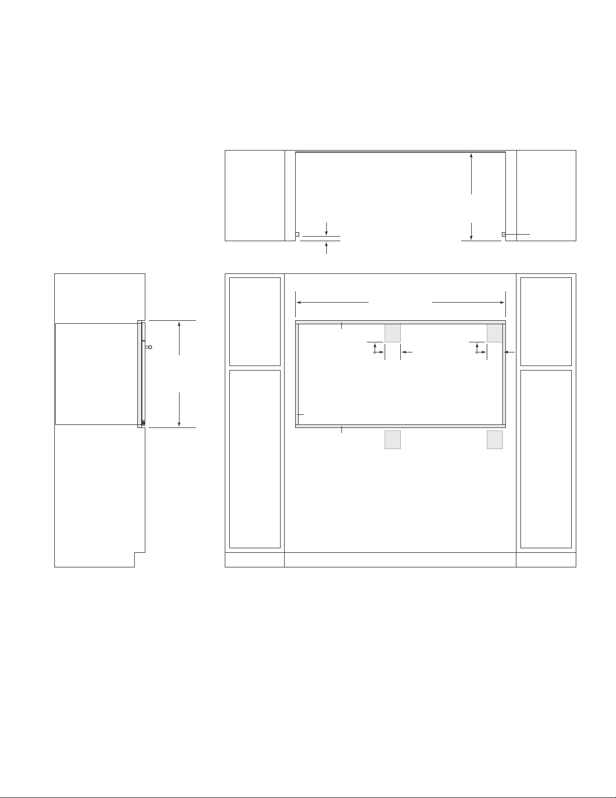
E
5 po
(127)
4"
(102)
E
5 po
(127)
4 po
(102)
VUE DE FACEVUE DE PROFIL
*Profondeur minimale de 1Êpo (25). Les zones ombragées seront visibles et doivent être finies pour s’agencer avec les armoires.
**La dimension fournit des jeux minimums.
REMARQUE : L’emplacement de l’alimentation électrique dans l’ouverture peut exiger une profondeur d’armoire supplémentaire.
Une trousse d’installation double est requise pour cette installation.
HAUTEUR
D’AFFLEUREMENT
DE 28
3
/4 po
(730)**
11/8 po (29)
1
/8 po (3)
13
/16 po (21)
PROFONDEUR
D'AFFLEUREMENT
DE 24 po (610)
7
/8 po (22)
LARGEUR D’AFFLEUREMENT DE
601/8 po (1 527)**
VUE DE DESSUS
EE
TAQUETS
FINIS*
Spécifications
Installation double à
Installation double à
affleurement d'un four
affleurement d'un four
simple 30 po (762)
simple 30 po (762)
wolfappliance.com | 35
Page 36
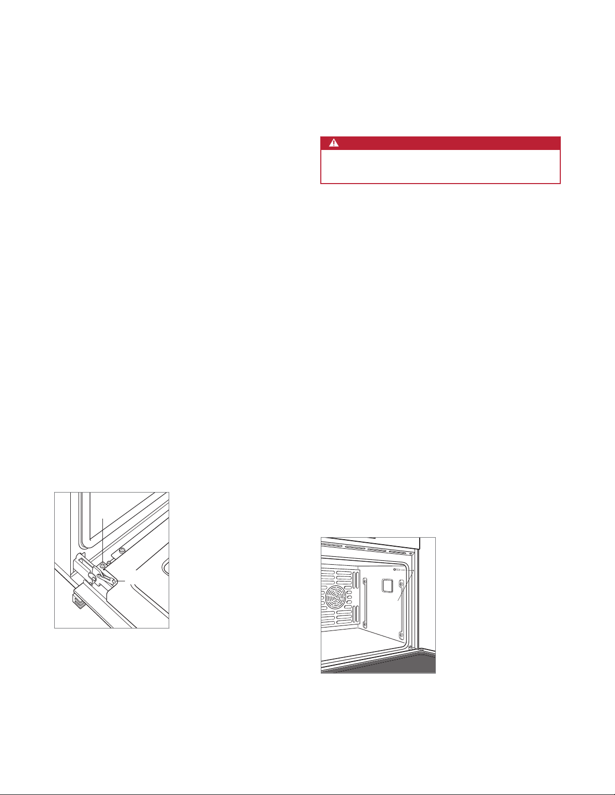
VIS
VERROU DE
CHARNIÈRE
TROU DE
MONTAGE
Installation
Préparation
Préparation
Connexion électrique
Avant de déplacer le four, protégez tout plancher fini et
fixez la (les) porte(s) du four en position fermée pour
éviter tout dommage.
Utilisez un chariot à appareil pour déplacer le four près de
l'ouverture. Placez le chariot à appareil sur le côté et
l’arrière pour éviter tout dommage. Retirez et recyclez les
matériaux d’emballage. Ne soulevez pas et ne transportez
pas le four par la poignée de porte.
Retrait de la porte du four
Pour alléger la charge, la (les) porte(s) du four peut
(peuvent) être retirée(s). Ne retirez la porte que si cela est
nécessaire. Le retrait de la porte ne doit être effectué que
par un technicien de service ou un installateur qualifiés.
Ne soulevez pas et ne transportez pas la porte du four par
la poignée.
Pour la retirer, ouvrez la porte complètement. Pivotez les
deux verrous de charnière complètement vers l’arrière,
retirez la vis située la plus près de la charnière des deux
côtés de la porte, puis tirez la porte vers l’avant.
Pour l'installer, glissez la porte dans les charnières. Pivotez
les verrous de charnière complètement vers l’avant et
installez les vis.
AVERTISSEMENT
Assurez-vous que le courant est coupé à partir du
coffret électrique avant de procéder.
Si l'alimentation électrique est située dans l'ouverture, la
connexion électrique doit être effectuée avant de placer
le four dans l'ouverture. Si l'alimentation électrique est
située dans une armoire adjacente, la connexion
électrique peut être effectuée après avoir placé le four
dans l'ouverture. La canalisation située à l'arrière de l'unité
permet une installation à trois ou quatre fils.
1
Reliez le fil d'appareil noir au fil d'alimentation noir
(L1).
2
Reliez le fil d'appareil rouge au fil d'alimentation rouge
(L2).
3
Reliez le fil d'appareil nu au fil de mise à la terre/vert.
4
Pour les systèmes à quatre fils, installez un coinceur à
câble sur le fil neutre/blanc.
Installation
Placez le four dans l'ouverture et glissez-le en position.
Pour obtenir une profondeur adéquate pour l'installation,
la canalisation doit pouvoir être insérée dans la zone
encastrée le long du rebord arrière du four.
36 | Français
Repérez le trou de montage dans chaque garniture
latérale. Percez des avant-trous de 1/16 po (2) et installez
des vis n° 6 x ¾ po.
Retirez et recyclez les matériaux d'emballage, y compris
le matériau protecteur blanc derrière chaque
emplacement de montage du guide de grille.
Page 37
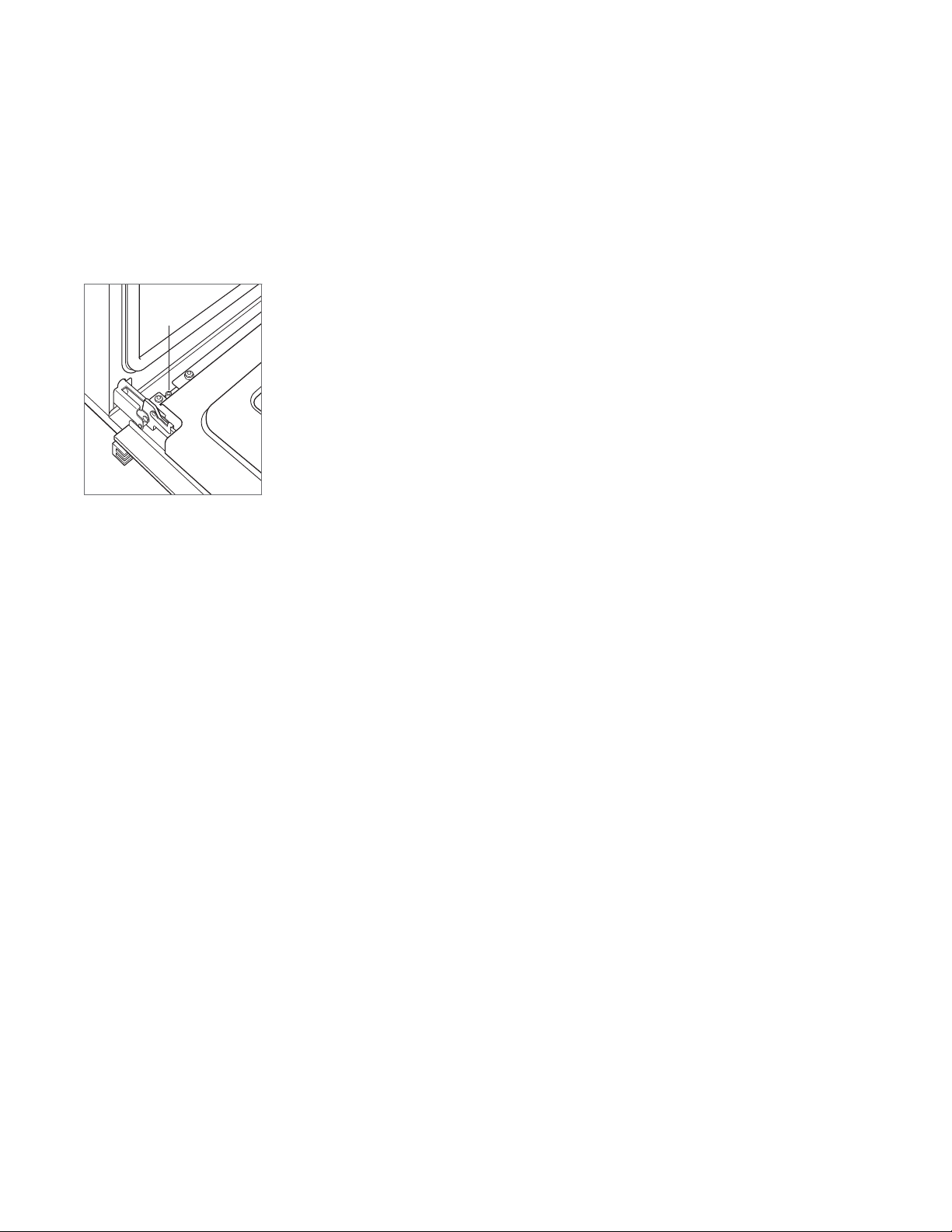
ÉCROU
Installation
Alignement de la porte
Alignement de la porte
Pour ajuster la porte, desserrez les écrous des deux côtés
de la porte, ajustez manuellement le bas de la porte d'un
côté à l'autre, puis serrez les écrous.
Dépannage
REMARQUE IMPORTANTE: Si la cuisinière ne fonctionne
pas correctement, suivez les étapes de dépannage
suivantes :
• Vérifiez l'alimentation électrique du four.
• Vérifiez les connexions électriques.
• Si le four ne fonctionne pas correctement,
communiquez avec le centre de service Wolf certifié
par l'usine. Ne tentez pas de réparer le four. Wolf n’est
pas responsable du service requis pour corriger une
installation défectueuse.
wolfappliance.com | 37
Page 38

WOLF APPLIANCE, INC. P.O. BOX 44848 MADISON, WI 53744 WOLFAPPLIANCE.COM 800.222.7820
9028912 REV-B 09/2020
*9028912$REVB*
 Loading...