

Wolf DF30, DF30-3, DF30-4,DF36-4,DF48-4,DF60-4, DF36-3, DF48-3 Technical & Service Manual
...Page 1
Dual Fuel Range
Technical Service Manual
© WOLF APPLIANCE, INC. 2007 ALL RIGHTS RESERVED JOB AID #804710 (Revision H)
DF30 - DF36 - DF48 - DF60
DF30-3 - DF36-3 - DF48-3 - DF60-3
DF30-4 - DF36-4 - DF48-4 - DF60-4
Page 2

Page 3

General Information
1-1
DDuuaall FFuueell RRaannggee
SECTION 1
GENERAL INFORMATION
Page 4

DDuuaall FFuueell RRaannggee
General Information
1-2
TECHNICAL ASSISTANCE
If you should have any questions regarding a Wolf
appliance and/or this manual, please contact:
Wolf Appliance, Inc.
ATTN: Service Department
P.O. Box 44988
Madison, WI 53744-4988
Customer Service & Parts / Warranty Claims
Phone #: (800) 332 - 9513
Technical Assistance
Phone #: (800) 919 - 8324
Customer Service & Technical Assistance
Facsimile #: (608) 441 - 5887
Parts / Warranty Claims
Facsimile #: (608) 441 - 5886
Office Hours:
7:00 AM to 7:00 PM Central Time
Monday through Friday
This manual is designed to be used by Authorized Service Personnel only. Wolf Appliance, Inc. assumes
no responsibility for any repairs made to Wolf appliances by anyone other than Authorized Service
Technicians.
IMPORTANT SAFETY INFORMATION
Below are the Product Safety Labels used in this manual. The "Signal Words" used are WARNING and
CAUTION.
Please note that these safety labels are placed in areas
where awareness of personal safety and product safety
should be taken and lists the precautions to be taken
when the signal word is observed.
INTRODUCTION
This Wolf Dual Fuel Technical Service Manual, Part #804710, has been compiled to provide the most recent technical service information about the Wolf Appliance, Inc., Dual Fuel Ranges. This information will enable the service
technician to troubleshoot and diagnose malfunctions, perform necessary repairs, and return a Wolf Dual Fuel
Range to proper operational condition.
The service technician should read the complete instructions contained in this Technical Service Manual before initiating any repairs on a Wolf Appliance.
* Some information in Section 3 (Operation Information) has been provided by the American Gas Association
and reprinted with AGA’s approval.
NOTE: Refer to the Dual Fuel Service Parts Manual #806375 for part numbers and exploded views for units produced prior to serial number 16000000 and Dual Fuel-3 Service Parts Manual #807040 for units produced after serial number 16000000.
INDICATES THAT HAZARDOUS OR UNSAFE PRACTICES COULD RESULT IN SEVERE PERSONAL
INJURY OR DEATH
Indicates that hazardous or unsafe practices could
result in minor personal injury or product and/or
property damage
In addition, please pay attention to the signal word
“NOTE”, which highlights especially important information within each section.
The information and images are the copyright property of Wolf Appliance, Inc., an affiliate of Sub-Zero, Inc. Neither
this manual nor any information or images contained herein may be copied or used in whole or in part without the
express written permission of Wolf Appliance, Inc., an affiliate of Sub-Zero, Inc. © Wolf Appliance, Inc., all rights
reserved.
Page 5

General Information
1-3
DDuuaall FFuueell RRaannggee
TABLE OF CONTENTS
Page #
Page #
Section 1 - General Information
Introduction......................................................................... 1-2
Important Safety Information.............................................. 1-2
Technical Assistance.......................................................... 1-2
Table of Contents............................................................... 1-3
Warranty Information......................................................... 1-5
Model Features.................................................................. 1-6
Model Key.......................................................................... 1-7
Model Descriptions............................................................ 1-8
Section 2 - Inst
allation Information
Electrical Requirements..................................................... 2-2
Gas Requirements............................................................. 2-3
Leak Testing....................................................................... 2-4
Installation Dimensions...................................................... 2-5
Unit Leveling...................................................................... 2-6
Section 3 - Operation Information
Theory of Operation........................................................... 3-2
Types of Fuel Gas........................................................... 3-2
Heating Value of Gas...................................................... 3-2
Specific Gravity of Gas................................................... 3-2
Principals of Gas Combustion............................................ 3-2
Requirements for Combustion........................................ 3-3
Chemistry of Combustion............................................... 3-3
Controlled Combustion................................................... 3-3
Total Air........................................................................... 3-3
Limits of Flammability...................................................... 3-3
Incomplete Combustion.................................................. 3-3
Gas Burner Operation..................................................... 3-3
Burner Components (PTS 17000000).................................3-4
Burner Head.................................................................... 3-4
Venturi............................................................................. 3-4
Inner Distribution Ring......................................................3-4
Outer Distribution Ring.................................................... 3-4
Jet Holder........................................................................ 3-4
Gas Orifice...................................................................... 3-4
Burner Components (SWS 17000000)............................... 3-5
Types of Burners................................................................ 3-6
Blue Flame Burners........................................................ 3-6
Infrared Burners.............................................................. 3-6
Operation of The Dual Fuel Range.................................... 3-7
Surface Burners.............................................................. 3-7
Grate Placement............................................................. 3-7
Control Knobs................................................................. 3-7
Burner Lighting................................................................ 3-7
Power Outage..................................................................3-7
Charbroiler....................................................................... 3-8
Charbroiler Operation..................................................... 3-8
Cleaning and Maintenance............................................. 3-9
Charbroiler Cleaning and Maintenance...........................3-10
Griddle Operation............................................................3-10
Griddle Care....................................................................3-10
Time of Day Clock...........................................................3-11
Oven Timer......................................................................3-11
Field Option Mode...........................................................3-11
UPO (User Preference Offset).....................................3-11
Changing Clock to 24 Hours........................................3-11
UPO (User Preference Offset).....................................3-11
Section 3 - Operation Information Cont’d
Field Option Mode..........................................................3-11
Changing Clock to 24 Hours...................................... 3-11
Fahrenheit to Celsius..................................................... 3-11
Cooking Modes..................................................................3-12
Bake Mode.................................................................... 3-12
Bake Stone Mode......................................................... 3-12
Broil Mode..................................................................... 3-13
Convection Mode...........................................................3-13
Convection Bake Mode................................................. 3-14
Convection Broil Mode.................................................. 3-14
Convection Roast Mode................................................ 3-15
Roast mode................................................................... 3-15
Oven Features.................................................................. 3-16
Dehydration Feature...................................................... 3-16
Proof Mode................................................................ 3-16
Proof Feature.................................................................3-16
Delayed Start Feature....................................................3-17
Probe Feature............................................................... 3-17
Sabbath Feature............................................................ 3-18
Self-Clean Feature........................................................ 3-18
Diagnostic Mode............................................................... 3-19
Initiating Diagnostic Mode..............................................3-19
Error Indicators................................................................. 3-20
Testing the Oven Relay Board......................................... 3-21
Element Testing............................................................. 3-21
RTD Testing................................................................... 3-21
Probe Testing.................................................................3-21
Fans and Motors Testing................................................3-22
Section 4 - Component
Access and Removal
Important Warnings and Cautions...................................... 4-2
Surface Burner Components.............................................. 4-3
Surface Burner Grate (PTS 17000000)...........................4-3
Burner Head with Cap (PTS 17000000)..........................4-3
Burner Cap (PTS 17000000)...........................................4-3
Venturi (PTS 17000000)..................................................4-4
Inner Distribution Ring (PTS 17000000)..........................4-4
Igniter (PTS 17000000)................................................... 4-4
Burner Grate and Burner Assembly (SWS 17000000)....4-5
Burner Pan and Trim Moldings (SWS 17000000)............4-5
Burner Pan - 6 Burner (PTS 17000000)........................ 4-6
Burner Pan - 2 Burner (PTS 17000000).........................4-6
Outer Distribution Ring (PTS 17000000).........................4-6
Jet Holder (PTS 17000000)........................................... 4-7
Deflector Shield (PTS 17000000)................................. 4-7
Spark Module (PTS 17000000).................................... 4-7
Burner Support (PTS 17000000).....................................4-7
Surface Burner Orifice (PTS 17000000)......................... 4-7
Orifice Removal (SWS 17000000....................................4-8
Orifice Holder (SWS 17000000)...................................... 4-8
Infrared Charbroiler Components...................................... 4-9
Electrode........................................................................ 4-9
Infrared Burner............................................................... 4-9
IR Orifice........................................................................ 4-9
PTS = Prior to Serial Number
SWS = Starting with Serial Number
Page 6

DDuuaall FFuueell RRaannggee
General Information
1-4
Page #
Page #
Section 4 - Component Access and Removal Cont’d
Infrared Griddle Components.......................................... 4-10
Grease Tray and Griddle................................................4-10
Thermostat Support Assembly...................................... 4-10
Electrode....................................................................... 4-10
IR WEld Assembly..........................................................4-10
Infrared Burner...............................................................4-10
Infrared Thermostat........................................................4-11
Solenoid.............................................................................4-11
IR Orifice.........................................................................4-11
Bull Nose Components..................................................... 4-12
Burner Knob...................................................................4-12
Burner Knob Bezel.........................................................4-12
Oven Selector Knob...................................................... 4-12
Function Selector Bezel................................................ 4-12
Bull Nose...................................................................... 4-12
Selector Switch............................................................. 4-13
Indicator Light............................................................... 4-13
ECH.............................................................................. 4-13
ECH Adjustment........................................................... 4-13
Components Behind the Bull Nose................................. 4-14
Valve Switch................................................................. 4-14
Burner Valve................................................................. 4-14
Charbroiler Valve.......................................................... 4-14
Griddle Shut-Off............................................................ 4-14
Manifold..........................................................................4-14
Control Board............................................................... 4-15
Relay Board.................................................................. 4-15
Motorized Door Latch................................................... 4-15
Transformer.................................................................. 4-15
Oven Door Components................................................. 4-16
Oven Door.................................................................... 4-16
Door.............................................................................. 4-16
Door Re-Installation...................................................... 4-16
Door Adjustments......................................................... 4-17
Door Gasket................................................................. 4-17
Outer Door Skin Assembly........................................... 4-18
Glass Pack................................................................... 4-18
Hinge............................................................................ 4-18
Hydraulic Hinge............................................................ 4-18
Oven Compartment Components.................................... 4-19
Oven Light.................................................................... 4-19
Convection Baffle Plate................................................ 4-19
Convection Fan Assembly............................................ 4-19
Broil Element and Broil Pan........................................ 4-19
Smoke Catalyst............................................................ 4-19
Temperature Sensor (RTD).......................................... 4-20
Probe Cover and Probe Switch.................................... 4-20
Hidden Bake Element................................................... 4-20
Side and Back Panel Components.................................. 4-21
Outer Side Panel.......................................................... 4-21
Cooling Fan.................................................................. 4-21
Thermo Limiter............................................................. 4-21
Section 5 - Troubleshooting Guide
How to Use the Troubleshooting Guide.............................. 5-2
Diagnostic Mode.............................................................. 5-2
Error Indicators................................................................. 5-2
Field Option Mode............................................................... 5-2
UPO (User Preference Offset)......................................... 5-2
Changing Clock to 24 Hours............................................ 5-2
Fahrenheit to Celsius....................................................... 5-2
Troubleshooting Guide Table of Contents........................... 5-3
General Troubleshooting Guide........................ 5-3 thru 5-10
Error Codes....................................................................... 5-10
ECH Troubleshooting Flow Chart...................................... 5-11
DSI Board Troubleshooting Flow Chart............................. 5-12
Testing the Oven Relay Board.......................................... 5-13
RTD Testing....................................................................... 5-13
Probe Testing.................................................................... 5-13
Fans and Motor Testing..................................................... 5-14
Ohm Testing Elements at Relay Board............................. 5-14
Section 6 - T
echnical Data
Technical Data Chart........................................................... 6-2
Orifice Quick Reference Chart............................................ 6-3
Operation Time Chart.......................................................... 6-4
Cooling Fan Operational Temperatures.............................. 6-4
Preheat Times..................................................................... 6-4
Section 7 - W
iring Diagrams
DF304, DF366, DF364C & DF364G Wiring Diagram......... 7-2
DF30, DF36 Schematic....................................................... 7-3
DF304 Rangetop Harness Diagram.................................... 7-4
DF364G Rangetop Harness Diagram................................. 7-4
DF364C Rangetop Harness Diagram................................. 7-5
DF366 Rangetop Harness Diagram.....................................7-6
DF48 Wiring Diagram...........................................................7-7
DF48 Schematic...................................................................7-8
DF486C Rangetop Harness Diagram..................................7-9
DF486G Rangetop Harness Diagram................................7-10
DF484F Rangetop Harness Diagram................................ 7-11
DF484CG Rangetop Harness Diagram..............................7-12
DF48DC Rangetop Harness Diagram............................... 7-13
DF484DG Rangetop Harness Diagram............................ 7-14
DF60 Schematic................................................................ 7-15
DF60 Wiring Diagram........................................................ 7-16
DF604CF Rangetop Harness Diagram............................. 7-17
DF604GF Rangetop Harness Diagram............................. 7-18
DF606CG Rangetop Harness Diagram..............................7-19
DF606DC Rangetop Harness Diagram............................. 7-20
DF606DG Rangetop Harness Diagram..............................7-21
DF606F Rangetop Harness Diagram.................................7-22
W
iring Diagrams Starting with Serial #16000000
DF304, DF366, DF364C & DF364G Wiring Diagram........7-23
DF30, DF36 Schematic......................................................7-24
DF48 Wiring Diagram.........................................................7-25
DF48 Schematic.................................................................7-26
DF60 Wiring Diagram........................................................ 7-27
DF60 Schematic................................................................ 7-28
Page 7
General Information
1-5
DDuuaall FFuueell RRaannggee
WARRANTY INFORMATION
This page contains a summary of the 2 & 5 Year Warranty that is supplied with every Wolf product, followed by
details and notes about the warranties.
TWO & FIVE YEAR Warranty Summary
• Two year TOTAL PRODUCT warranty, parts and labor.
• Limited Parts Only Warranty for the 3rd through 5th year on the following parts only:
Electric heating elements
Electronic Control Boards
Warranty Details:
The warranty applies only to products installed for normal residential use. The warranty applies only to product
installed in the United States or Canada.
Warranty Notes:
• All warranties begin at the time of the unit’s initial installation.
• All Warranty and Service information collected by Wolf Appliance, Inc. is arranged and
stored under the unit serial number and/or the customer’s name. Please note that Wolf Appliance, Inc. requests
that you have the model serial number available whenever contacting the factory or parts distributor.
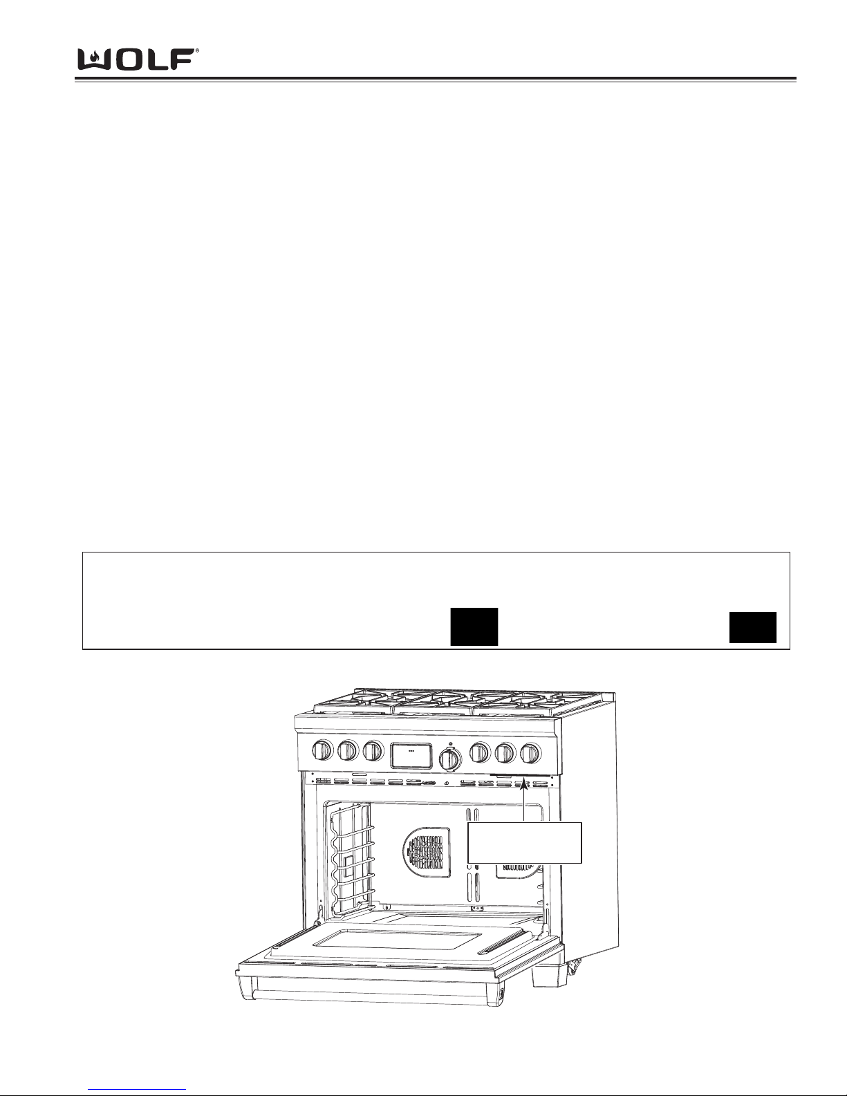
• See Figure 1-1 for serial tag layout.
• See Figure 1-2 for serial tag location.
Wolf Appliance Company, LLC
Fitchburg, WI
Gas INPUT RATING EACH BURNER - BTU/HR
Man. Press. Left Rear Burner – Other Top Burners Griddle – Charbroiler – French Top –
ELECTRICAL RATING: Volts – Amps – Hertz -
Model # - Serial # -
BD
MINIMUM HORIZONTAL CLEARANCE FROM SIDES AND BACK OF APPLIANCE TO ADJACENT COMBUSTIBLE CONSTRUCTION EXTENDING 18” ABOVE THE COOKING SURFACE 12” FROM SIDE WALLS 0” FROM
REAR WALL MINIMUM CLEARANCE BETWEEN ADJACENT COMBUSTIBLE MATERIALS BELOW THE
COOKING SURACE AND THE BACK AND SIDE OF THE APPLIANCE: 0”. MAXIMUM DEPTH FOR OVERHEAD
CABINETS IS 13” MINIMUMBERTICAL DISTANCE BETWEEN THE COOKING SURFACE AND THE BACK AND
SIDE OF THE APPLIANCE: 30”, MINIMUM VERTICAL DISTANCE BETWEEN THE TOP BROILER GRID TO
UNPROTECTED OVERHEAD COMBUSTIBLE SURFACES 36”, MINIMUM HORIZONTAL DISTANCE BETWEEN
OVERHEAD CABINETS INSTALLED TO EITHER SIDE OF THE APPLIANCE SHALL NOT BE LESS THAN THE
NOMINAL WIDTH OF APPLIANCE TO BE USED IN CONJUNCTION WITH A SUITABLE VENT HOOD ONLY.
COOKING UTENSILS SHALL NOT BE USED ON AN OPEN TOP BROILER SECTION, MINIMUM HORIZONTAL
CLEARANCE FROM ISLAND INSTALLTION COOKTOP TO COMBUSTIBLE SIDE AND BACK WALL IS 12”
“ANSI Z21.1 “HOUSEHOLD GAS COOKING APPLIANCES”
“CSA IR 58, 1995”
Figure 1-1. Typical Serial Tag Layout
Figure 1-2. Serial Tag Located Underneath the Bottom of the Control Panel
Serial Tag Located
Underneath Bottom
of Control Panel
Page 8

DDuuaall FFuueell RRaannggee
General Information
1-6
MODEL FEATURES
• Natural or LP gas rangetop with dual convection electric oven(s)
• Small 18-inch oven on 48-inch dual fuel range is single convection
• Stainless steel exterior finish
• Platinum bezel surrounds all knobs, Chrome and Bronze optional
• Option of Red or Black knobs
• Dual stacked sealed 15,000 burners with automatic re-ignition at all settings
• Dual stacked burners all have simmer capabilities
• Melt feature on one 9,200 Btu burner
• 11” or 22” 15,000 BTU (13,000 BTU - LP) Griddle with Infrared burner(s) and safety shut off system
• 11” or 22” 16,000 BTU Charbroiler with Infrared burner(s)
• 22” 15,000 BTU French Top burner with safety shutoff system
• Continuous cast iron porcelain top grates
• Pivoting touch control panel
• Coaxial temperature displaying oven knob
• Eight cooking modes
• Bake Mode
• Bake Stone Mode
(30” and 36” cavities only)
• Broil Mode
• Convection Mode
• Convection Bake Mode
• Convection Broil Mode
• Convection Roast Mode
• Roast Mode
• Proof Mode (18” only)
• Self-cleaning oven(s)
• Dehydration Feature
• Proof Feature (30” and 36” cavity)
• Delayed Start Feature
• Probe Feature
• Sabbath Feature
• Spring/damper door system
• Temperature probe
• Full extension bottom rack
• Hidden bake element
• Oven door windows and dual halogen lighting
• Blue porcelain oven interior
• Adjustable stainless steel legs in front and adjustable rear casters
• Optional Bake Stone
• High altitude conversion kit available for units installed above 8,000 feet
• Two and five year residential warranty
• CSA certified for US and Canada
Page 9
General Information
1-7
DDuuaall FFuueell RRaannggee
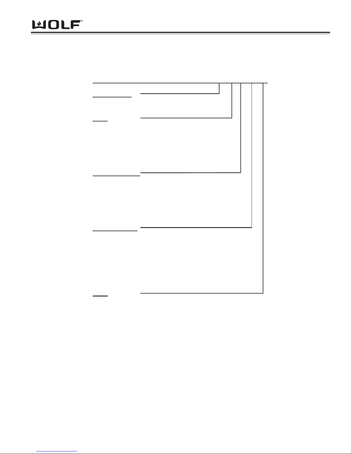
MODEL NUMBER KEY
Refer to this key for an example of the model numbers.
Model: DF 36 6 CG-LP
Product Type
DF Dual Fuel
Size
30 30 - inch wide unit
36 36 - inch wide unit
48 48 - inch wide unit
60 60 - inch wide unit
Surface Burners
2 2 - Sealed burners
4 4 - Sealed burners
6 6 - Sealed burners
Model Features
C Charbroiler (11")
G Griddle (11")
F French Top (22")
DG Griddle (22")
DC Charbroiler (22")
Fuel
LP Propane Gas
Page 10
DDuuaall FFuueell RRaannggee
General Information
1-8
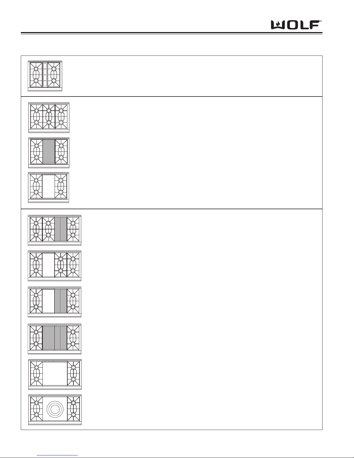
TOP CONFIGURATIONS OF 30”, 36” and 48” DUAL FUEL RANGES
DF486C 48” Dual Fuel Range with Six Burners and 11” Charbroiler
DF486G 48” Dual Fuel Range with Six Burners and 11” Griddle
DF484CG 48” Dual Fuel Range with Four Burners and 11” Charbroiler and
11” Griddle
DF484DC
48” Dual Fuel Range with Four Burners and 22” Double Charbroiler
DF484DG 48” Dual Fuel Range with Four Burners and 22” Double Griddle
DF484F 48” Dual Fuel Range with Four Burners and 22” French Top
DF304 30” Dual Fuel Range with Four Burners
DF366 36” Dual Fuel Range with Six Burners
DF364C 36” Dual Fuel Range with Four Burners and 11” Charbroiler
DF364G 36” Dual Fuel Range with Four Burners and 11” Griddle
Page 11
General Information
1-9
DDuuaall FFuueell RRaannggee
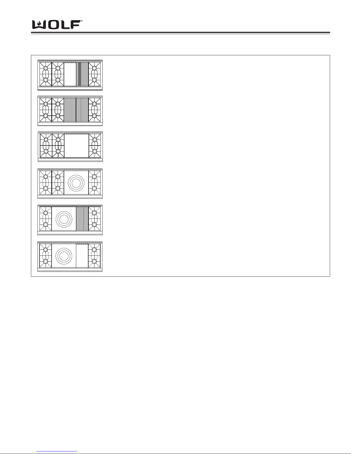
TOP CONFIGURATIONS OF 60” DUAL FUEL RANGES
DF606CG 60” Dual Fuel Range with Six Burners and 11” Charbroiler and
11” Griddle
DF606DC 60” Dual Fuel Range with Six Burners and 22” Charbroiler
DF606DG 60” Dual Fuel Range with Six Burners and 22” Griddle
DF606F 60” Dual Fuel Range with Six Burners and 22” French Top
DF604CF 60” Dual Fuel Range with Four Burners and 11” Charbroiler and
22” French Top
DF604GF 60” Dual Fuel Range with Four Burners and 22” French Top and 11”
Griddle
Note: LP units will be designated with a -LP at the end of the model number.
Page 12

DDuuaall FFuueell RRaannggee
General Information
1-10
Page 13

Installation Information
2-1
DDuuaall FFuueell RRaannggee
SECTION 2
INSTALLATION
INFORMATION
Page 14
DDuuaall FFuueell RRaannggee
Installation Information
2-2
INSTALLATION INFORMATION
This section of the manual covers some of the installation issues that a service technician may need to know when
servicing a Wolf Dual Fuel Range. If additional installation information is needed after reviewing this section of the
manual, please refer to the Installation Guide or contact the Wolf Appliance Customer Service Department.
Electrical Requirements
Required Electrical Supply
• 240 volts AC, 60 Hertz, 30 ampere fused electrical supply for 30” and 36” units.
• 240 volts AC, 60 Hertz, 50 ampere fused electrical supply for 48” and 60” units.
• Separate circuit serving only this appliance.
• Installation site must be equipped with a properly grounded receptacle.
Maximum Connected Load
• 5,200 Watts for 30” and 36” units.
• 10,000 Watts for 48” and 60” units.
Minimum Electrical Wire Size
30” and 36”
• L1 and L2 - 12 AWG
• Neutral - 16 AWG
• Ground - 12 AWG
48” and 60”
• L1 and L2 - 8 AWG
• Neutral - 12 AWG
• Ground - 10 AWG
The unit is designed with a terminal block on the rear of the range. The terminal block allows for 3-wire or 4-wire
installation. For a 4-wire installation, the ground strap from the unit to the terminal block must be cut. Two concentric knockouts (on the terminal block), are provided to allow a certified electrical contractor to wire the range directly
to a junction box.
The terminal block will also accept an appliance power cord. The power cord must be sized correctly for the units
voltage and amperage.
Please refer to state, municipal and local codes for the best means to connect the appliance to the electrical power
supply.
A SHOCK HAZARD COULD EXIST IF THE ELECTRIC RECEPTACLE OR THE POWER CORD ARE
NOT PROPERLY GROUNDED AND POLARIZED.
The appliance may experience ignition problems if
not properly grounded and polarized.
Page 15
Installation Information
2-3
DDuuaall FFuueell RRaannggee
Gas Requirements
Wolf Dual Fuel Ranges are manufactured to work with natural gas or LP gas (Liquid Propane gas). The model /
serial rating plate, located on the bottom of the control panel assembly just above the oven door on the far right, has
information on the type of gas that should be used. If this information does not agree with the type of gas available,
check with the local gas supplier.
Natural Gas Manifold Pressure
Standard natural gas orifices on the appliance are set for 5” WC (Water Column Pressure).
Liquid Propane Manifold Pressure
The standard propane gas orifices on the appliance are set for 10” WC (Water Column Pressure).
Gas Supply Line Size
• 3/4 inch rigid pipe to the range location
• For LP gas, piping or tubing size can be 1/2"
minimum.
NOTE: A smaller size pipe on long runs may result in insufficient gas supply.
A CSA design-certified, 3-foot long, 1/2" or 3/4" ID,
flexible metal appliance connector is recommended
for connecting this range to the gas supply line.
Gas Supply Pressure
• Maximum line pressure for natural gas and LP is 14” WC; 1/2 psi (3.5 kPa).
• Minimum line pressure for natural gas is 7” WC.
• Minimum line pressure for LP gas is 11” WC.
Gas Pressure Regulator
To control and maintain a uniform gas pressure in the
gas manifold, Wolf gas appliances must be connected
to the gas supply line through a pressure regulator.
The burner orifices are sized for the pressure delivered
by the regulator. Never attempt to operate a Wolf gas
appliance without the use of the proper pressure
regulator.
The maximum gas supply pressure to the regulator
should never exceed 14” WC (Water Column
Pressure); 1/2 psi (3.5kPa)
Do not kink or damage the connector when moving
the range
Page 16
DDuuaall FFuueell RRaannggee
Installation Information
2-4
Gas Shut-off Valve
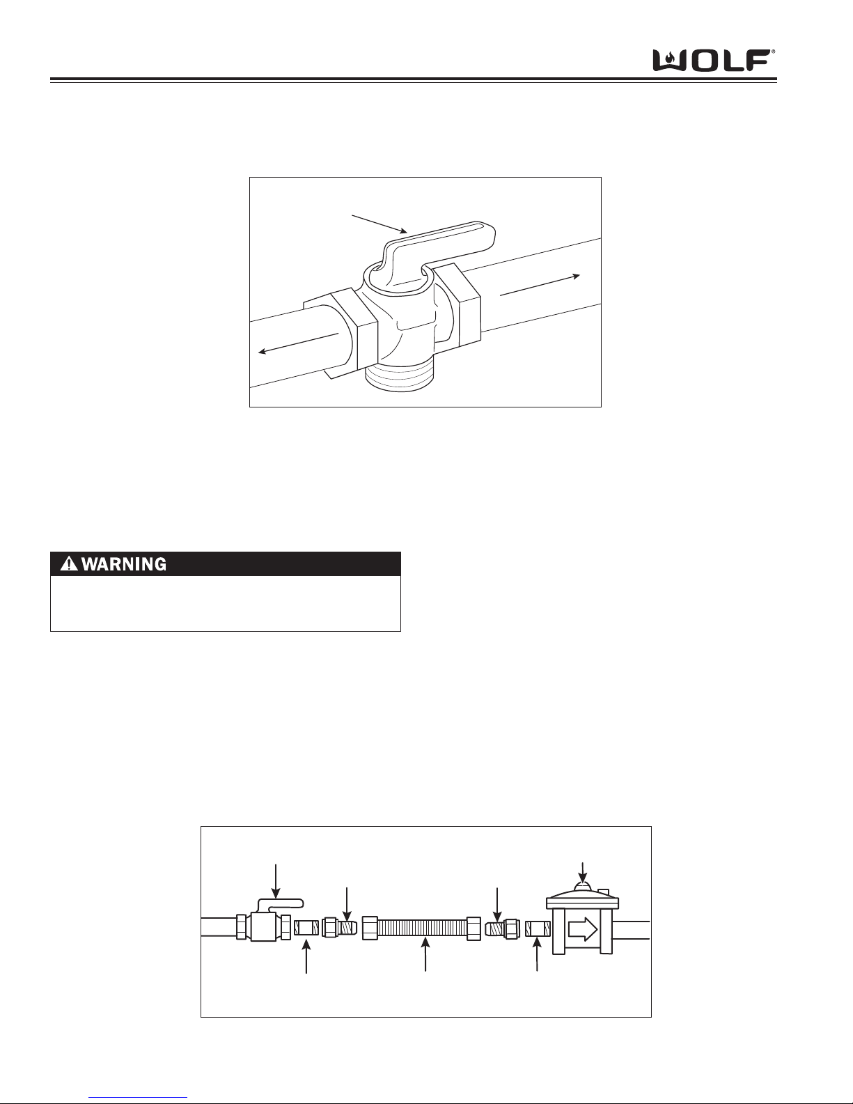
The supply line must be equipped with an approved shut-off valve. This valve should be located in accordance to all
national, local codes and ordinances. (See Figure 3-1).
Leak Testing
Use a brush and liquid detergent to test all gas connections for leaks. Bubbles around connections will indicate a
leak. If a leak appears, shut off gas valve controls and adjust connections. Then check connections again. Clean all
the detergent solution from the range.
An electronic leak detector can also be utilized to test for leaks.
Supply Line Connection
All connections must be wrench-tightened. Do not make connections to gas piping too tight. Making the connection
too tight may crack regulator and cause a gas leak. Do not allow pipes to turn when tightening fittings, tubing in the
burner box may also bend and begin to leak.
Assemble flexible metal connector from gas supply pipe to pressure regulator. Determine fittings required, depending on size of gas supply line, flexible metal connector and shut-off valve. (See Figure 3-2).
Use a pipe-joint compound made for use with natural and LP gas. If flexible metal connector is used, be
sure tubing is not kinked.
NEVER USE OPEN FLAMES TO CHECK FOR GAS
LEAKS. DO NOT USE LIQUID NEAR VALVE
STEMS.
Shut-off Valve
(open position)
To Cooktop
Gas Supply Line
Fig. 3-1. Shut-off Valve
Manual
Shut-off Valve
1/2" Adapter
1/2" Adapter
Pressure
Regulator
1/2" Nipple
(use pipe-joint compound)
1/2" Nipple
(use pipe-joint compound)
Flexible Metal Connector
Fig. 3-2. Gas Connection
Page 17
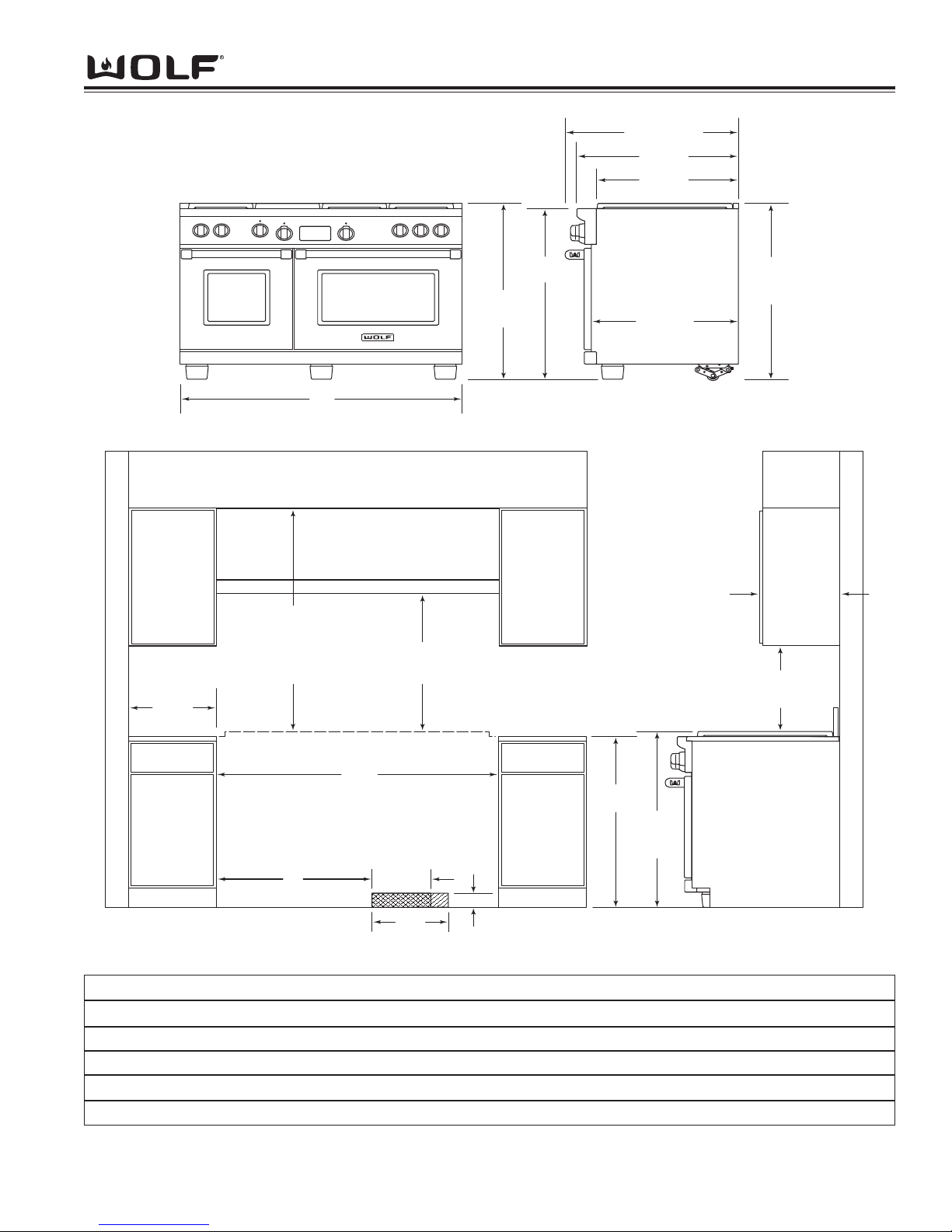
Installation Information
2-5
DDuuaall FFuueell RRaannggee
E
LOCATION OF
ELECTRICAL
36"
(91.4)
367/8"
(93.7) TO
COOKING
SURFAC
E
30" min (76.2)
COOKING SURFACE
TO COMBUSTIBLE
CONSTRUCTION
44" min (91.4)
TO CHARBR
OILER
30" min (76.2)
TO BOTTOM OF
VENTILA
TION HOOD
VENTILATION HOOD
COMBUSTIBLE CONSTR
UCTION
18" min (45.7)
TO COOKING
SURFACE
13" max
(33.0)
LOCATION OF GAS AND
ELECTRICAL EXTENDS 3"
ON FLOOR FROM BACK WALL
ISLAND INSTALLATIONS: 12" MINIMUM
CLEARANCE FROM BACK OF RANGE
TO COMBUSTIBLE CONSTR
UCTION
B
FINISHED ROUGH OPENING WIDTH
COOKING SURFAC
E
C
31/4"
(8.3)
D
LOCATION
OF GAS
SUPPL
Y
6" min
(15.2)
TO WALL
357/8"
(91.1)
367/8" (93.7)
TO COOKING
SURFACE
367/8"
(93.7)
OVERALL
HEIGHT
A
O
VERALL WIDTH
25"
(63.5)
241/4"
(61.6)
271/2"
(69.9)
291/2" (74.9)
OVERALL DEPTH
LEGS AND CASTERS ALLOW
21/8"
HEIGHT ADJUSTMENT
Installation Dimensions
I
nstallation Dimensions 30" Range 36" Range 48" Range 60" Range
A *Overall width of range 29 7/8" 35 7/8" 47 7/8" 60 1/8"
B Finished rough opening width 30" 36" 48" 60 1/4"
C Dimension from edge of rough opening 8 1/2" 8 1/2" 24" 31"
D Location of gas supply 10" 15" 10" 10"
E Location of electrical 13" 19" 13" 13"
*width may vary to +1/8"
Figure 3-3. Dimension Chart
Page 18
DDuuaall FFuueell RRaannggee
Installation Information
2-6
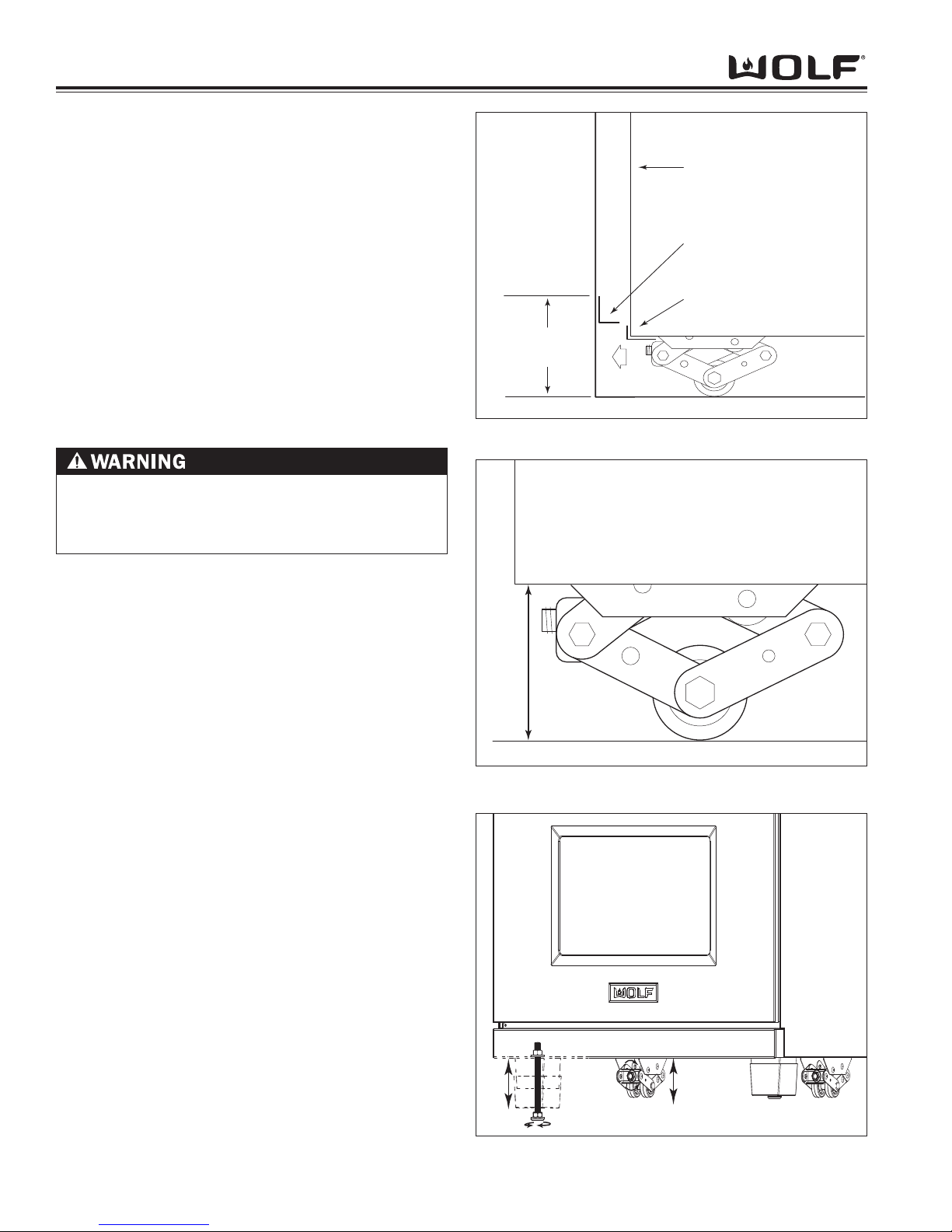
Anti-Tip Bracket Installation
Raise the unit to desired height using the rear leveling
casters and adjusting the front adjustable legs.
Try fitting the unit in place to verify the correct height.
Measure from the floor to the top of the range base
flange on the back of the unit. Add 1/8" to this dimension, mark this height on the wall behind the unit. This
will be the location of the bottom edge of the anti-tip
bracket. Try to center the mark between the cabinets.
For 48-inch and 60-inch ranges, care must be taken to
verify that the anti-tip bracket does not interfere with the
inner cavity supports. Locate a stud or other solid
mounting source, install the anti-tip bracket at the same
level as this line. Push the unit back, ensure the rear
base flange fits under the anti-tip bracket. (See Figure
3-3).
Unit Leveling
Rear Caster Adjustment
The Dual Fuel range has rolling casters, which allows
easy movement of the range by picking up on the front
of the unit. The range comes from the factory at an
overall height of 35-7/8" (from floor to the top of the
bullnose) before any height adjustment. The casters
allow for 2-1/8" height adjustment.
NOTE: Do not lift by oven door(s) handle.
To raise or lower rear caster, reach directly underneath
unit to rear caster and attach a 3/4” socket with an long
extension onto the adjusting bolt located on front of
caster assembly. Now, attach a drill or socket wrench
to extension and turn bolt left or right to raise or lower.
(See Figure 3-6)
Front Leveling Leg Adjustment
Dual Fuel ranges can be leveled at the front by turning
the front leveling legs as indicated in figure 3-6 The
legs allow for 2-1/8" height adjustment.
To raise or lower front leveling legs, use an adjustable
wrench to turn the leveling leg nut to the left or right to
raise or lower. (See Figure 3-6).
The stainless steel cover over the leveling leg floats up
or down to conceal the leveling leg from view. If leveling leg is still visible and the stainless steel cover is all
the way down, replace the stainless steel cover with a
longer version, available as a sales accessory.
ANTI-TIP BRACKET MUST BE ANCHORED TO
WALL BEHIND UNIT SO IT IS DIRECTLY ABOVE
THE BASE FLANGE OR APPLIANCE MAY TIP FORWARD
SIDE PANEL
ANTI-TIP
BRACKET
BASE FLANGE
WALL
FLOOR
TO FLOOR
5 3/4" min.
Figure 3-4. Anti-Tip Installation
CASTERS ALLOW
2 1/8" HEIGHT ADJUSTMENT
FLOOR
Figure 3-5. Caster Height
Figure 3-6. Caster and Leveling Leg Adjustment
Page 19

Operation Information
3-1
DDuuaall FFuueell RRaannggee
SECTION 3
OPERATION
INFORMATION
Page 20

DDuuaall FFuueell RRaannggee
Operation Information
3-2
THEORY OF OPERATION
A service technician should understand how a gas appliance operates before attempting to service the appliance.
This section provides descriptions of the different types of fuel gases and explains gas heating values. A definition
of specific gravity of gas is given along with its characteristics and effects. Gas combustion principals are explained
and gas burner components are described and illustrated. The end of this section contains illustrations which
demonstrate basic cooking appliance theory of operation.
Types of Fuel Gas:
Gases used to supply heat energy are called fuel gases. Common fuel gases are not simply one kind of hydrocarbon, they are mixtures of hydrocarbon gases. They contain other gases as well, such as free hydrogen, carbon
dioxide and nitrogen. As an example natural gas might contain 85% methane, 12% ethane and 3% of other gases.
The presence of each of these gases in the fuel gas has some effect on the nature of the gas.
Some common fuel gasses are methane [CH
4], ethane [C2H6], Propane [C3H8] and butane [C4H10]. Propane and
butane are nearly odorless. Natural gas that is processed to remove condensables and moisture, has little or no
odor and no color. Odorants are added to natural gas before distribution to aid in leak detection. A common odorant
used is a colorless liquid containing sulfur compounds.
Heating Value of Gas:
Heat energy produced when burning a fuel gas is commonly expressed in British Thermal Units (BTU). One BTU of
heat will raise the temperature of one pound of water one degree Fahrenheit.
The more carbon and hydrogen atoms in each molecule of a fuel gas, the higher its heating value. Natural gas
which is high in methane has a heating value of about 950 to 1150 BTU per cubic foot. The variance is due to the
various other substances found in natural gases. The more ethane, propane or butane in the gas raises the heating
value. Propane, or LP gas, has a heating value of about 2500 BTU per cubic foot, and butane about 3200 BTU per
cubic foot.
Specific Gravity of Gas:
The specific gravity of a gas is the weight of one cubic foot, or the gas compared to one cubic foot of dry air. When
stating the specific gravity of a gas, a pressure and temperature must be clearly stated. In the gas industry, the
standard conditions of pressure and temperature are 30.0 inches of mercury and 60° F. A pressure of 30.0 inches of
mercury will sustain a column of mercury 30 inches high in a tube with a vacuum on top of the column. Since air is
used as the reference, its specific gravity is always 1.0. This value of 1.0 has no direct physical meaning with
regard to air, such as its density. It is only a relative number or ratio used to express specific gravity of other gases.
The specific gravity of a gas will determine if the gas will rise or fall when released into the air. Natural gas will rise
since its specific gravity is less than 1.0 at 0.4 to 0.8. Propane has a specific gravity of 1.5 and butane 2.0. These
gases will fall when released into the air. They sometimes collect in low spots into pools which become a hazard if
open flames are present.
In addition, specific gravity has two other characteristics. It has an important effect on the flow of gases through orifices, and hence the rating of the burners. Gas flow through an orifice is dependent upon the orifice size and the
gas pressure upstream of the orifice. More of a lighter gas will flow through a given orifice size than a heavier gas
at the same gas pressure. This effect is taken into account in tables and calculators used to select orifice sizes for
burners.
The gas flow in pipes is also affected by specific gravity. At a given pressure at a pipe inlet, more lighter gas will
flow through a pipe than a heavier gas.
Principals of Gas Combustion:
Combustion
When oxygen acts with a substance to produce large amounts of heat rapidly.
Page 21

Operational Information
3-3
DDuuaall FFuueell RRaannggee
Requirements for Combustion
There are three required elements for combustion to occur; Fuel (Gas), Oxygen (Air) and Heat (Ignition
Temperature, which for gas is between 1100°F/593°C and 1200°F/649°C). All must be present. Removing any one
of the three and combustion will cease.
Chemistry of Combustion
Combustion of gas is a chemical reaction between fuel gas and oxygen. The basic elements of common fuel
gasses are hydrogen [H] and carbon [C]. When hydrogen burns, water vapor [H
2O] is produced. Complete burning
of carbon in fuel gases form carbon dioxide [CO2] and water vapor [H2
O].
Controlled Combustion
Controlled combustion takes place when gas and air are supplied at proper rates to assure complete combustion of
the gas in a steady flame. When a gas appliance is operating properly, burning starts at the burner ports. Gas flow
is controlled by gas orifice size and gas pressure upstream of the orifice. Air is mixed with the gas before it passes
through the burner ports. This added air is called “Primary Air”. The remaining air required for complete combustion
is supplied to the burner at the point of combustion and is called “Secondary air”.
Adjustments of the gas-to-air ratio and the secondary air supply is the key to obtaining stable blue flames at a burner. Proper amounts of primary and secondary air are required for quiet and efficient burner operation and for complete combustion of the gas. Air Shutters or other devices provide control of primary air. Inlet opening and flue outlets control Secondary Air flow.
Total air
In an ideal situation, primary and secondary air is all that is needed (for the oxygen required) to burn the gas, but
some additional air is required to assure complete burning of the gas. The total air, “primary”, “secondary” and
“excess” are expressed as percentages of the amount needed. About ten cubic feet of air is required to completely
burn one cubic foot of gas. For this reason an appliance should not be operated in an air tight home.
Limits of Flammability
Not all air-to-gas mixtures will burn. Mixtures with 0% - 4% natural gas in air are too lean to burn. Mixtures of 4% 14% natural gas in air can burn with a controlled flame. Flammability limits come into play when primary air adjustments are made on burners. If too much primary air is used, the mixture may become too lean and fall below flammability limits, thus preventing combustion.
Incomplete Combustion (Causes and Effects)
To obtain complete combustion, sufficient amounts of air must be supplied to the process. This air must have a reasonably normal oxygen content. Complete burning of gas produces harmless carbon dioxide gas and water vapor.
If the air supply is insufficient, incomplete combustion occurs resulting in the formation of toxic by-products, such as
carbon monoxide [CO] or aldehydes.
Carbon monoxide is colorless and odorless. Inhaling carbon monoxide in sufficient quantities could cause death by
reducing oxygen levels in the blood.
Aldehydes, which are equally dangerous, have a sharp and penetrating odor which is easily detected by smell at
very low concentrations. The odor caused by aldehydes should not be confused with odorants added to natural gas.
The absence of aldehydes does not assure that carbon monoxide is not present. However, if the odor of aldehydes
is present, then carbon monoxide is virtually always present.
Gas Burner Operation
A gas burner is a device to burn gas under control in order to produce useful heat. Primary air is brought into the
burner from outside of the appliance at atmospheric pressure. The gas jet streaming from the orifice draws primary
air with it into the burner.
The gas/air mixture, combined with a spark at the burner port(s) and the secondary air creates a controlled burn.
Page 22
DDuuaall FFuueell RRaannggee
Operation Information
3-4
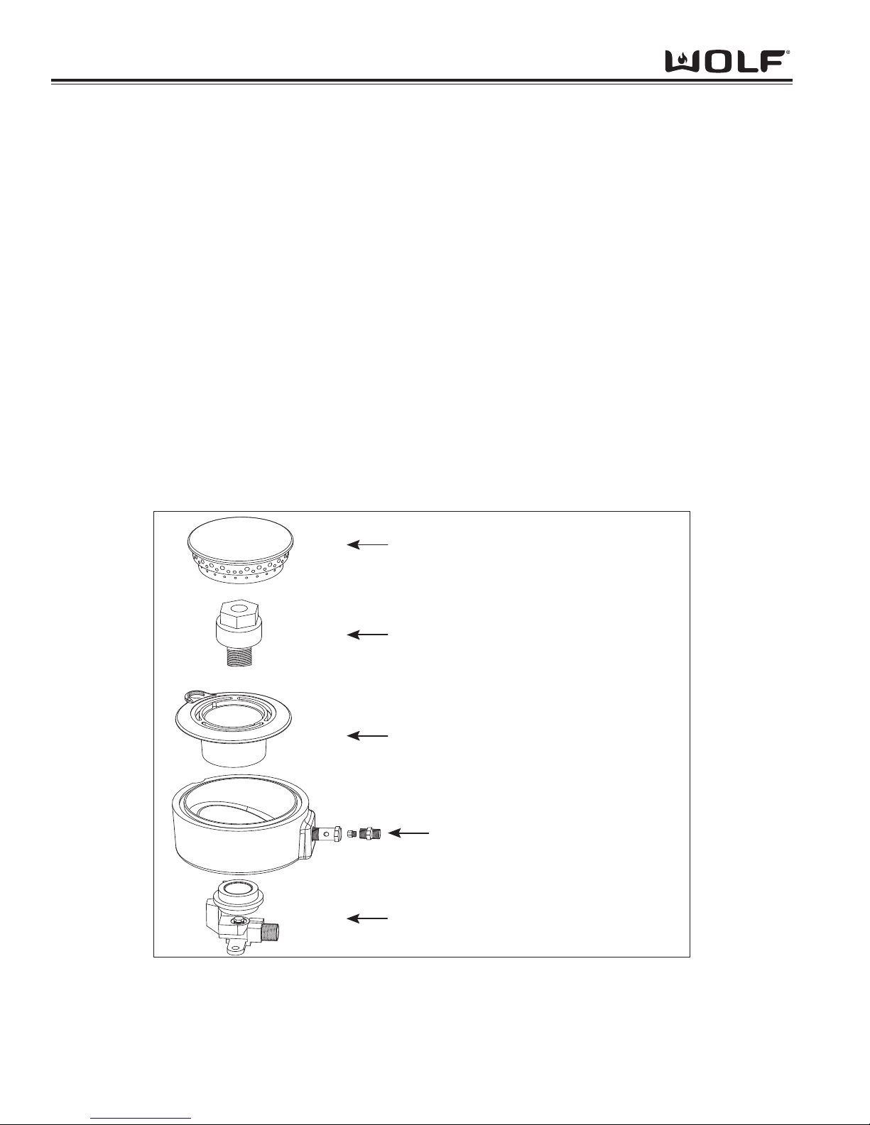
Burner Components: (PTS 17000000)
Burner Head - The component containing the burner ports where the gas/air mixture ignites. The burner ports are
distributed in a useful pattern to optimize heat transfer. The flames should be spread so they can be easily reached
by secondary air and provide a stable blue flame.
Venturi - Threaded brass pipe that threads into the jet holder through the distribution rings which narrows and then
flares out again. This pipe helps maintain proper and constant primary air injection.
Inner Distribution Ring - Routes the gas from the simmer orifice hood to the simmer port holes located on the
burner cap.
Outer distribution Ring - Routes the gas from the main burner orifice hood to the main burner port holes on the top
of the burner head.
Jet Holder - This component is mounted to the burner mounting bracket and to the burner box. The main burner
orifice is threaded into the jet holder as well as the venturi. It is the main support for the burner components.
Gas Orifice - An opening or hole which regulates or limits the amount of gas flowing to a burner. Gas flow rate (volume) depends on the size of the orifice (hole) and the gas pressure at the inlet of the orifice.
Burner Head
Venturi
Inner Distribution Ring
Outer Distribution Ring
Jet Holder
with Connector and Orifice
with Orifice
Figure 3-1. Burner Components
Page 23
Operational Information
3-5
DDuuaall FFuueell RRaannggee
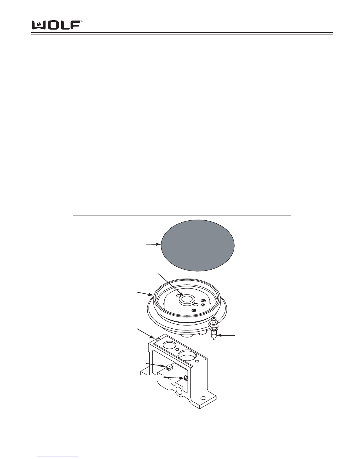
Figure 3-1A. Burner Components
Electrode
Burner
Burner Cap
Orifice Holder
Simmer Orifice
Main Orifice
Venturi
Burner Components: SWS 17000000
Burner Cap - Provides the upper portion of the ports required to create a combustible mix and proper flame quality
of the burner and the decorative top for the burner with a black porcelain coating.
Burner - Contains the burner ports where the gas/air mixture ignites. The burner ports are distributed in a useful
pattern to optimize heat transfer. The flames should be spread so they can be easily reached by secondary air and
provide a stable blue flame. The burner also incoorporates the Inner Distribution Ring, which Routes the gas from
the simmer orifice to the simmer port holes, and the Outer Distribution Ring, which routes the gas from the main
burner orifice to the main burner port holes.
Venturi - Helps maintain proper and constant primary air injection.
Electrode - The Electrode supplies the spark to ignite the burner. The electrode senses the flame, once the burner
is ignited and will stop sparking. If no flame is sensed, and the valve is opened, the electrode will start sparking to
re-ignite the flame. This is part of the auto-reignition system.
Orifice Holder - This component is mounted to the burner mounting bracket and to the burner box. The Simmer
and Main orifice is threaded into the orifice holder and routes the gas to the appropriate ports of the burner. It is the
main support for the burner components.
Simmer Orifice and Main Orifice - An opening or hole which regulates or limits the amount of gas flowing to a
burner. Gas flow rate (volume) depends on the size of the orifice (hole) and the gas pressure at the inlet of the orifice.
Page 24
DDuuaall FFuueell RRaannggee
Operation Information
3-6
Types of Burners:
Blue Flame Burners
All Wolf open surface burners, including the French Top burners are blue flame burners. With this type of burner,
primary air is mixed with the fuel gas before the gas reaches the burner ports. An orifice is used to regulate gas
flow to the burner and is sized to draw exact amount of air into the burner body. Air, which is mixed with the gas
inside the burner body then exits the burner ports located in the burner head, where it is ignited. Secondary air is air
from around the flames. The flame produced has several zones, each represents a stage in burning of the gas.
The burner tip has a thin dark blue cone called the inner or primary cone. A lighter cone called the outer cone, surrounds the inner cone. Air around the flame diffuses into the flame to burn at the outer cone. If conditions are perfect, products from the inner cone burn here. The final products of burning are carbon dioxide and water vapor. An
outer mantle surrounds the outer cone where burning is usually completed. It is nearly invisible and glows only
because of the high temperature of the final combustion.
Infrared Burners
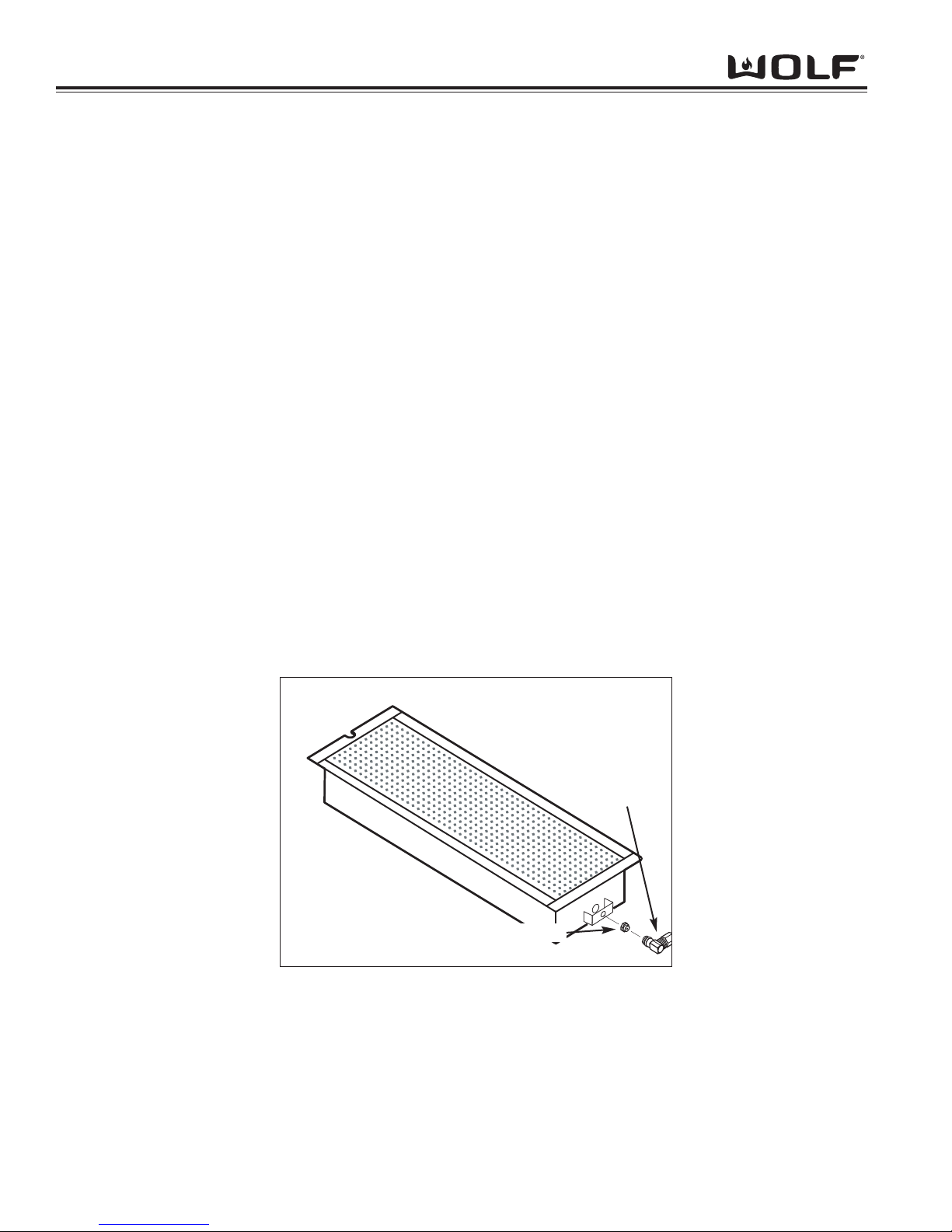
Wolf dual fuel ranges also use infrared burners. The under-fired application for the charbroiler and the griddle uses
a porous refractory ceramic tile burner. (See Figure 3-2) With this type of burner, a substantial amount of energy
output is in the form of infrared radiant energy. With infrared heat, thermal energy is transmitted through space without heating the medium through which it travels. Infrared energy is usually not affected by air flowing between the
burners and heated surfaces because of the burner’s numerous and tiny flames. This type of heat is very efficient
and compact. The under-fired refractory infrared burner requires 100 percent primary air and is designed to have a
hot glowing burner surface. The flame burns close to the burner surface at a high temperature.
NOTE: There is no shutter on infrared burners for adjusting the primary air and there is no change in orifice size for
different altitude.
Figure 3-2. Infrared Burner
CHARBROILER AND GRIDDLE ORIFICE
GAS ORIFICE
ELBOW
Page 25

Operational Information
3-7
DDuuaall FFuueell RRaannggee
OPERATION OF THE DUAL FUEL RANGE
Surface Burners
A spark electrode ignites each surface burner. This control eliminates the need for continuous open flame pilots.
For added safety and convenience, each burner is designed with an electronic re-ignition system. This feature
enables any burner to automatically re-light in the event it is accidentally extinguished.
This unique dual stacked burner design combines all the burner parts in one configuration. Large burners provide a
Btu/hr rating of 15,000 on HIGH and a High Simmer Btu/hr rating of approximately 3300. Small burners provide a
Btu/hr rating of 9,200 on HIGH and a High Simmer Btu/hr rating of approximately 1600. All burners have simmer
settings.
A distinguishing feature of the Wolf low Btu/hr control is its constant, low heat output without continuous ignitions.
Flame diameter remains full size, only the heat output is lowered. This is the ultimate control for simmering food.
After removing burner parts for any reason, it is extremely important that the burners are re-assembled correctly.
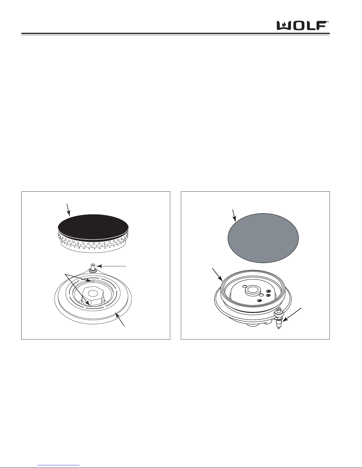
The burner cap has a special orientation and should be seated flatly (see Figure 3-3 and Figure 3-3A).
Rotate burner cap until you feel it drop and click into position.
This patented dual stacked burner configuration makes it possible to enjoy cooking at full flame as well as maintaining control while simmering at the lowest flame setting.
Grate Placement
Low profile cast iron grates are designed for a close fit. This enables pans to move easily from one burner to another without having to lift the pan or have it tip over between the grates. Each grate sets securely on dimples on each
corner of the cooktop pan. Continuous grates are interchangeable.
Control Knobs
The control knobs are positioned to correspond to the burners they regulate. The knobs on the far left regulate the
burners on the left side. Conversely, the knobs on the far right regulate the burners on the right side.
Burner Lighting
To light a burner push in and turn the corresponding control knob counter clockwise to the HIGH setting. You will
hear “clicking” and see the burner ignite. Once the burner is lit, continue turning the knob counter clockwise to any
one of the settings, HIGH through LOW.
To select a simmer setting, turn the knob to the LOW setting. You will feel a stop-detent in the knob rotation. Push
in on the knob, continuing to turn it counter clockwise. This moves the flame to the second tier. Now, select any
variation within the SIMMER flame settings, HIGH through LOW.
Each knob is designed to be a “push-to-turn knob”. Although this is a child-safe design, children should never be left
unattended in the kitchen when the range is in use.
Power Outage
In case of a power outage, the surface burners can be re-lit manually. Turn the control knob to “high” and place a
flame near the igniter to light the burner.
DSI board operation (Griddle & French Top units only)
The DSI board serves the purpose of igniting the griddle burner, detecting the presence of this flame, and provides
the signal to open the gas valve. When the thermostat is turned on, the red (call for heat) light comes on and the
gas solenoid is opened. At this time you will hear a series of sparks and it will begin to check for the presence of a
flame. If the igniter probe does not detect flame within a short period of time, the gas valve solenoid shuts off and
there will be a delay before trying to reignite (this allows time for the non-combusted gas to dissipate). This process
will reoccur in three sets and if it fails a third time the DSI board will shut down and will wait for the thermostat to be
turned off and on before attempting to reignite. If flame detection is lost during operation this board will also allow
time for the non-combusted gas to dissipate, but will attempt to reignite after this delay.
Page 26
DDuuaall FFuueell RRaannggee
Operation Information
3-8
Burner Cap
Igniter
Sealed Burner
Alignment
Tabs
Figure 3-3. Stacked Dual Burner Assembly (PTS 17000000)
Charbroiler
This optional feature is designed with an infrared burner to give the highest quality and most efficient method of gas
grilling. These burners become an orange-red color at the surface of the ceramic tiles. When the tiles are glowing,
they transfer an intense heat to the food being grilled. This chars the outside of the food and leaves the inside tender and juicy.
The infrared burner is designed to operate at a full heat output of 16,000 BTU/hr. It is recommended using the Wolf
blank-off plate when grilling most foods.
Charbroiler Operation
• Turn on the ventilation hood prior to using the charbroiler.
• If the knob is not set fully at "HIGH", the burner may turn blue and the automatic igniter will begin sparking.
Turn the knob back to "HIGH".
• Preheat grill for about ten minutes before adding the food. The tiles will have an orange glow.
• For the 22-inch charbroiler, there are two separate burners with separate control knobs, which act
independently of each other.
Burner Cap
Igniter
Sealed Burner
Figure 3-3A Stacked Dual Burner Assembly (SWS 17000000)
Page 27
Operational Information
3-9
DDuuaall FFuueell RRaannggee
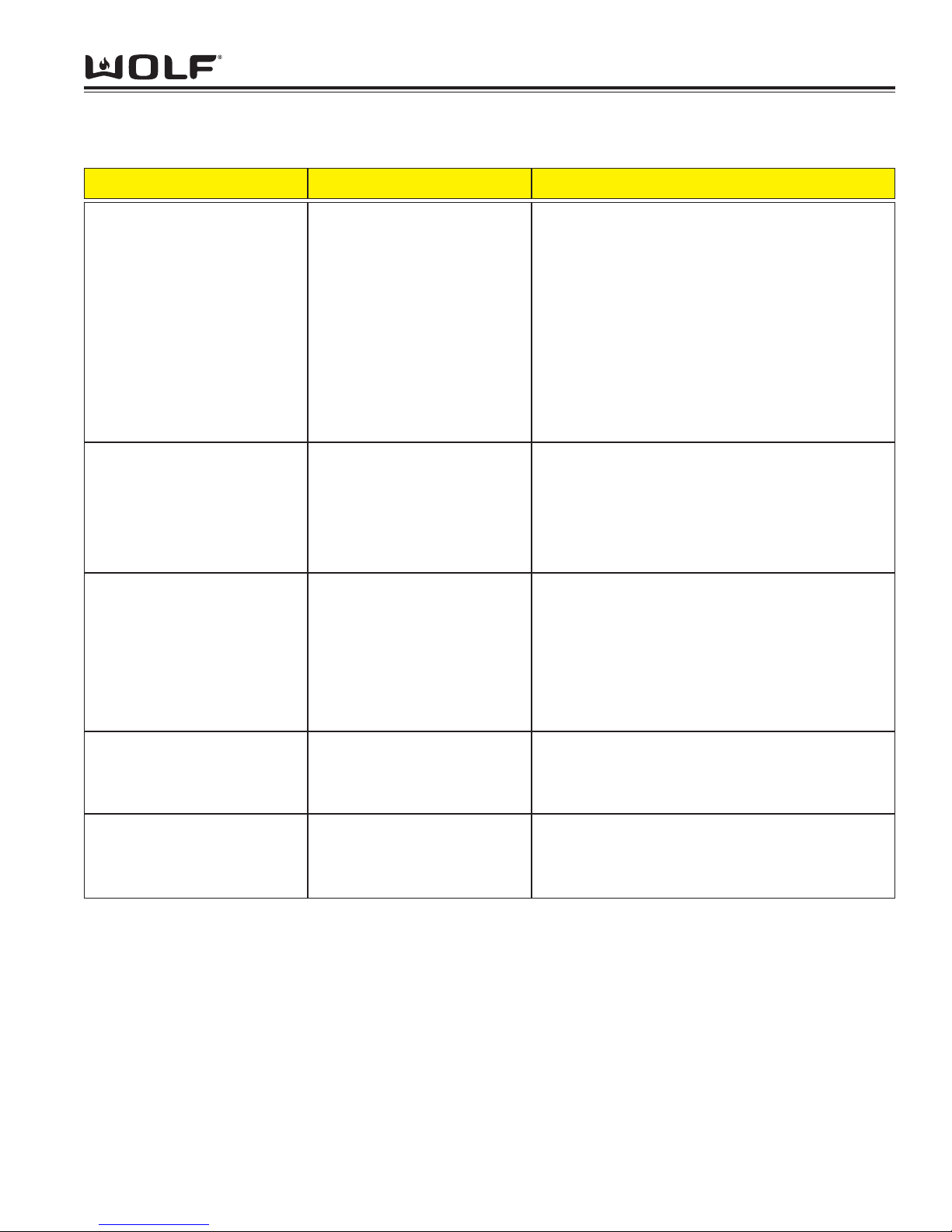
Burner Pan
Although resistant to most
stains, it is not totally impervious to damage. Salt and
some cooking liquids may pit
and stain surface. Always
remove these spills immediately.
Avoid using abrasive cleaners;
they will permanently scratch
the surface.
Burner Cap
Burner Grates
Control Knobs
Spark Igniters
Part Identification Material Care Recommendation
Exterior Finish
Porcelain Steel
Porcelain Enamel
(matte finish)
Never wipe a warm or hot
porcelain surface with a damp
sponge; it may cause chipping
or crazing (tiny hair-like cracks)
Porcelain-Coated Cast Iron
Metal
Ceramic
General care: Use a clean cloth or sponge, wipe
with warm water and mild detergent. Rinse and
dry immediately. Apply protective polish, always in
the same direction.
Spray degreaser: Removes fingerprints and
greasy spatters. Spray on a cloth and wipe surface. Buff dry immediately to avoid streaking.
Protective polish: Apply to surface to maintain luster and protect from some food stains
Hard water stains: Use white vinegar and water.
Cool first. Wash in warm water with liquid detergent or mild abrasive cleaners.
Foods high in acid or sugar content, such as milk,
tomatoes, sauerkraut, fruit juices and pie filling,
may pit or craze the surface. Remove as soon as
possible. Do not cook the spill on again.
Remove from cooktop and place on a flat surface
near the sink.
Non-abrasive cleaners: Hot water and liquid detergent, paste of baking soda and water, plastic pad
or sponge.
Mild abrasive and abrasive cleaners: Use sparingly.
General care: Wipe each knob with a damp cloth
and mild soap and water; rinse and dry. Never
soak or use abrasive cleaners; they will scratch the
finish and remove the markings.
Keep dry. Never spray water or cleaner directly on
the igniter. When cleaning around the surface
burner, be careful that the cloth does not catch on
the igniter and damage it.
Cleaning and Maintenance
Page 28
DDuuaall FFuueell RRaannggee
Operation Information
3-10
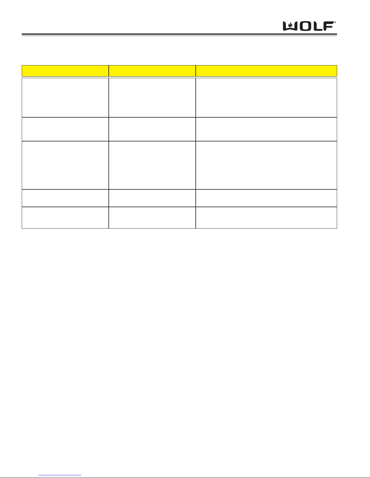
Blank-Off Plate
(If Applicable)
Charbroiler Frame
Grate
Igniter
Mesh Screen
(If Applicable)
Part Identification Material Care Recommendation
Stainless Steel
Stainless Steel
Porcelain Coated
Cast Iron
Ceramic
Stainless Steel Wire
Wash with hot water and detergent. Use a soapfilled scouring pad to remove as much cooked-on
soil as possible. The plate will turn a metallic blue
color due to high heat; this is a permanent
change.
Remove from the range. Soak in hot water and
dish detergent. Wash thoroughly, scrubbing with
scouring pad, if needed. Rinse and dry.
When cool, lift off and set in the sink. Pour very
hot water over the cooked-on residue. Cover with
wet dish towels and pour more hot water over it.
Allow the hot, moist conditions time to help loosen
the residue. Remove remaining soil with a soapfilled scouring pad. Rinse and dry.
Avoid contact with the igniter; it is fragile and can
chip or break.
Use a wire brush to loosen any charred food particles.
Charbroiler Cleaning and Maintenance
Griddle
The cast iron griddle plate operates at 18,000 Btu/hr. It is thermostatically, controlled which means once the set
temperature is reached, the heat cycles to hold that setting. Prior to use it is necessary to "season" the griddle to
protect the surface from moisture. This process will change the appearance.
NOTE: Seasoning does not create a non-stick surface. The use of additional oil is necessary during cooking.
Griddle Operation
• To heat the griddle, push in the knob and turn counter clockwise to desired temperature. It is normal to hear a
clicking sound. This is the electronic ignition lighting the burner. When the burner is lighted, the thermostat will
control the temperature.
• Preheat for approximately 10 to 15 minutes. When the griddle is preheated, the griddle indicator light will go
out. The light will cycle on and off as the thermostat needs more heat to maintain the set temperature. This will
allow heat to be evenly distributed and reach the set temperature.
• For the 22-inch griddle, there are two separate burners with separate control knobs, which act independently of
each other.
• To turn off the griddle, turn the knob clockwise to the "OFF" position.
Griddle Care
• Use a metal spatula and scrape grease into the grease collection tray.
• When the surface has cooled, wipe it with a paper towel to remove excess grease or oil.
• Clean grease collection tray after each use. Do not allow grease to accumulate in the tray and become a fire
hazard.
• To remove the drip tray, gently pull the tray towards yourself to lift it out. Clean drip tray with soapy water and a
clean cloth.
Page 29
Operational Information
3-11
DDuuaall FFuueell RRaannggee
Time of Day Clock
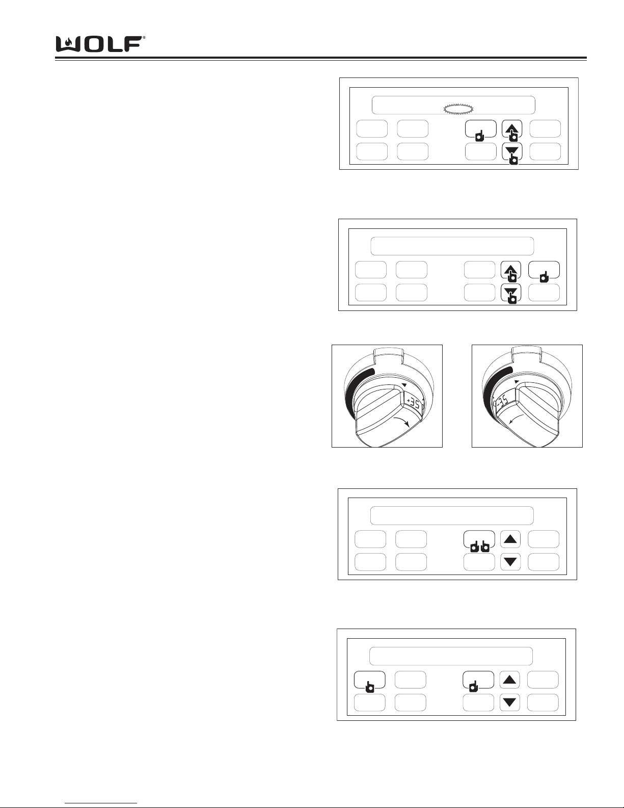
The clock can be visible on the display during all modes. To
set clock, press the CLOCK key on display panel, “CLOCK”
will flash on and off. Next, press the up or down arrow key to
increase or decrease the time. Stop when correct time of day
shows in display window. (See Figure 3-4). Now, press the
CLOCK key or ENTER key to set clock. Two beeps will be
heard when time has been entered.
NOTE: By holding down desired arrow key, counter will rapidly toggle through the numbers.
NOTE: Time will change from am to pm by passing the 12:00
mark.
Oven Timer
The oven has a timer that operates independently from the
oven controls. Once a time is set in hours and minutes, the
countdown is seen in the display window. Only the last
minute counts down in seconds. To initiate oven timer, press
TIMER key. (See Figure 3-5). Next, press the arrow up or
arrow down key to increase or decrease desired amount of
cooking time in hours and minutes. (See Figure 3-5). Then,
press ENTER key or TIMER key to start timer. Two beeps will
be heard. The oven will chime, time will continually flash
when timing is complete. To exit oven timer function, press
TIMER key, then press CLEAR key twice to clear time and
return to clock.
FIELD OPTION MODE
Three Field option modes allows for the user to adjust or
change specific option’s of the ECH and oven controller, such
as User Preference Offset, 12 hour to 24 hour clock and
Fahrenheit to Celsius temperature.
UPO (User Preference Offset)
This option allows the user to offset a specific oven temperature ±35° in 1°F (Fahrenheit) increments. To initiate, press
and hold the CLOCK key for 5 seconds. The current UPO will
be displayed in the temperature readout knob, turning the
knob at this point you can change the UPO. Turn the knob to
the left or right to increase or decrease the UPO in 1° increments as much as ±35°. (See Figure 3-6 and 3-7).
Changing Clock to 24 Hours
To set 24 hour clock, press and hold CLOCK key on display
panel for 5 seconds. (See Figure 3-8). Now, press CLOCK
key to change from 24 hour to 12 hour or vice versa. (See
Figure 3-8). Then, press the ENTER or after short delay the
clock will set by default.
Fahrenheit to Celsius
The oven can be changed from Fahrenheit to Celsius temperature or visa versa. To initiate, press and hold the CLOCK
key on display panel for 5 seconds. Now, press the COOKTIME key to change from °F and °C or visa versa. (See
Figure 3-9). Next, press the ENTER key on the display panel
or after short delay °F or °C will set by default.
COOK
TIME
PROBE
CLOCK
ENTER
TIMER
CLEAR
STOP
TIME
OVEN
LIGHT
1:00
CLOCK
P
1
2
2
2
2
Figure 3-4. First, Press and Hold CLOCK Key for 5
Seconds. Then, Press Arrow Up or Arrow Down Key to
Set Time
COOK
TIME
PROBE
CLOCK
ENTER
TIMER
CLEAR
STOP
TIME
OVEN
LIGHT
12hr
°F
1
2
2
Figure 3-8. First, Press and Hold CLOCK Key for 5
Seconds. Then, Press CLOCK Key to toggle between 12hr
and 24hr
COOK
TIME
PROBE
CLOCK
ENTER
TIMER
CLEAR
STOP
TIME
OVEN
LIGHT
0:00
1
2
2
2
2
Figure 3-5. First, Press TIMER Key. Then, Use Arrow Up
or Arrow Down Key to Set Desired Amount of Time
COOK
TIME
PROBE
CLOCK
ENTER
TIMER
CLEAR
STOP
TIME
OVEN
LIGHT
12hr
1
°C
2
2
Figure 3-9. First, Press and Hold CLOCK Key for 5
Seconds. Then, Press COOK TIME Key to Toggle
between °F and °C
O
F
F
B
A
K
E
B
R
O
I
L
B
A
K
E
B
R
O
I
L
R
O
A
S
R
O
A
S
T
HI
LO
Figure 3-6. Turn Knob to
Right to increase temper-
ature
O
F
F
B
A
K
E
B
R
O
I
L
B
A
K
E
B
R
O
I
L
R
O
A
S
R
O
A
S
T
HI
LO
Figure 3-7. Turn Knob to
Left to decrease tempera-
ture
Page 30

DDuuaall FFuueell RRaannggee
Operation Information
3-12
COOKING MODES
The dual fuel oven has multiple cooking modes, each dedicated to give the best results for a specific kind of cooking. The
dual fuel oven also has some unique cooking features.
Most oven modes have a temperature setting of 170°F (75°C)
to 550°F (290°C). The exception is Broil, Convection Broil
and Proof mode.
NOTE: Bake Stone Element must be removed during all
cooking modes excepts Bake Stone Mode.
Bake Mode
Both the hidden bake element and broil element are used to
heat the air and cycle to maintain temperature. This mode is
best for single rack cooking, primarily bakery foods.
To initiate the Bake Mode, turn oven control knob bezel counter clockwise to BAKE. (See Figure 3-10). Temperature is
preset to 350°F (175°C). To change oven temperature, immediately turn temperature readout knob to the right to increase
oven temperature or to the left to decrease. (See Figure 3-11
and 3-12). Oven will turn on after 2 seconds or press ENTER
key. To exit Bake Mode, turn oven knob bezel to OFF.
NOTE: Always preheat for Bake mode.
NOTE: Temperature probe may be used in this mode.
NOTE: Timer function may be used during this mode.
NOTE: The temperature display alternates between set and
actual oven temperatures during preheat.
NOTE: Temperatures below 150°F (65°C) are displayed by
the word "Lo" in the oven knob display window during preheat
NOTE: Oven will chime when oven preheat temperature has
been achieved.
Bake Stone Mode
A specially designed rack and heating element are used for
this mode to produce a hot oven environment necessary for
baking on a ceramic stone. A heating element is added
under the stone to enhance the heat from both convection
fans.
To initiate Bake Stone Mode, turn the oven control knob bezel
clockwise to STONE. (See Figure 3-14). Temperature is preset at 400°F (205°C). To change temperature, immediately
turn temperature readout knob to right to increase oven temperature or to left to decrease. (See Figure 3-15 and 3-16).
Oven will turn on after 2 seconds or press ENTER key. To
exit Bake Stone Mode, turn oven knob bezel to OFF.
NOTE: “Stone” will appear and flash on hidden display and a
beep tone will be heard 30 seconds if the bake stone element
is not inserted into receptacle.
NOTE: Always preheat 25 minutes for Bake Stone mode.
Oven will chime when oven preheat temperature has been
achieved.
NOTE: Temperature probe may be used in this mode.
NOTE: Timer function may be used during this mode.
NOTE: The temperature display alternates between set and
actual oven temperatures during preheat.
B
A
K
E
B
R
O
I
L
R
O
A
S
T
B
R
O
I
L
O
F
F
B
A
K
E
B
R
O
I
L
5
0
3
LO
HI
Figure 3-10. Turn Control
Knob Bezel Counter
Clockwise to BAKE
HI
LO
B
A
K
E
B
R
O
I
L
R
O
A
S
T
B
R
O
I
L
O
F
F
B
A
K
E
B
R
O
I
L
3
5
1
Figure 3-11. Increase
Preset Temperature, Turn
Knob to Right
B
A
K
E
B
R
O
I
L
R
O
A
S
T
B
R
O
I
L
O
F
F
B
A
K
E
B
R
O
I
L
HI
LO
3
4
9
Figure 3-12. Decrease
Preset Temperature, Turn
Knob to Left
B
A
K
E
B
R
O
I
L
R
O
A
S
T
B
R
O
I
L
O
F
F
B
A
K
E
B
R
O
I
L
o
L
LO
HI
Figure 3-13. Lo appears
in display window if tem-
perature is below 150°F
4
0
0
LO HI
S
T
O
N
E
R
O
A
S
T
B
R
O
I
L
C
L
E
A
N
C
O
N
V
R
O
B
A
K
E
Figure 3-14. Turn Control
Knob Bezel Counter
Clockwise to STONE
HI
LO
S
T
O
N
E
R
O
A
S
T
B
R
O
I
L
C
L
E
A
N
C
O
N
V
R
O
B
A
K
E
Figure 3-15. Increase
Preset Temperature, Turn
Knob to Right
HI
LO
S
T
O
N
E
R
O
A
S
T
B
R
O
I
L
C
L
E
A
N
C
O
N
V
R
O
B
A
K
E
Figure 3-15. Decrease
Preset Temperature, Turn
Knob to Left
L
o
LO HI
S
T
O
N
E
R
O
A
S
T
B
R
O
I
L
C
L
E
A
N
C
O
N
V
R
O
B
A
K
E
Figure 3-16. Lo appears
in display window if tem-
perature is below 150°F
Page 31
Operational Information
3-13
DDuuaall FFuueell RRaannggee
Broil Mode
The top element is used to conduct an intense, radiant
heat which browns one side of the food at a time. This
mode is best for meats, fish and poultry pieces up to 1inch thick.
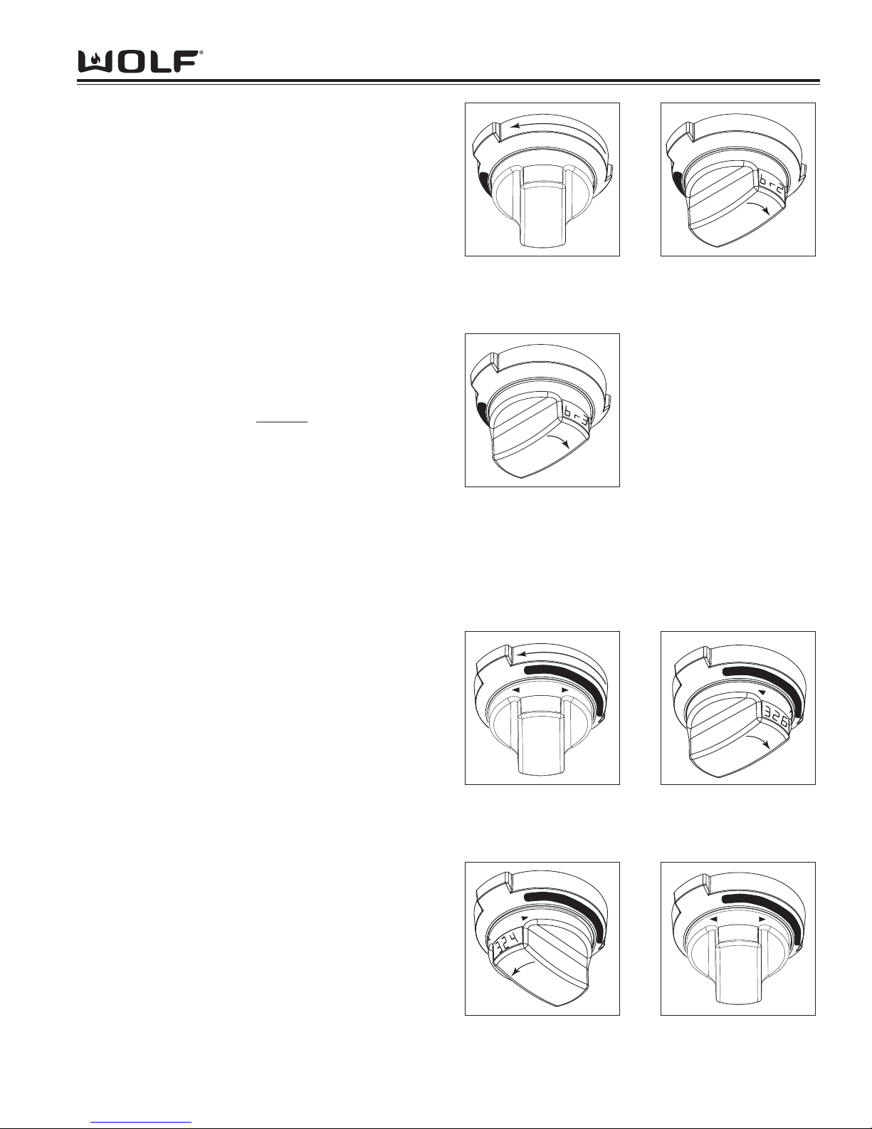
To initiate Broil Mode, turn oven control knob bezel
counter clockwise to BROIL. (See Figure 3-17).
Temperature is preset to "br1" for 550°F (290°C)-Hi
Broil. To change oven temperature, immediately turn
the temperature readout knob to left to decrease oven
setting to "br2" for 450°F (230°C)-Med Broil or "br3" for
350°F (175°C)-Low Broil. (See Figure 3-18 and 3-19).
Oven will turn on after 2 seconds or press ENTER key.
To
exit Broil Mode, turn oven control knob bezel to OFF.
NOTE: Timer function may be used during this mode.
NOTE: Never preheat for Broil mode.
NOTE: Temperature probe may not
used in this mode.
Convection Mode
Dual convection fans, each with a heating element,
operate from the back of the oven and move heated air
throughout the entire oven cavity. Uniform air movement makes it possible to cook on all six rack levels
simultaneously. The heat is cycled on and off to maintain temperature, resulting in evenly browned food.
To initiate Convection Mode, turn oven control knob
bezel clockwise to the dark area on dial marked CONV.
(See Figure 3-20). Temperature is preset at 325°F
(160°C). To change oven temperature, immediately
turn the temperature readout knob to right to increase
oven temperature or to left to decrease oven temperature setting. (See Figure 3-21 and 3-22). Oven will
turn on after 2 seconds or press ENTER key. To exit
Convection Mode, turn oven knob bezel to OFF.
NOTE: Always preheat for Bake mode.
NOTE: Temperature probe may be used in this mode.
NOTE: Timer function may be used during this mode.
NOTE: The temperature display alternates between set
and actual oven temperatures during preheat.
NOTE: Temperatures below 150°F are displayed by
the word "Lo" in the oven knob display window during
preheat.
NOTE: Oven will chime when oven preheat temperature has been achieved.
br1
B
A
K
E
B
R
O
I
L
R
O
A
S
T
S
T
O
N
E
O
F
F
B
A
K
E
Figure 3-17. Turn Control
Knob Bezel Counter
Clockwise to BROIl
B
A
K
E
B
R
O
I
L
R
O
A
S
T
S
T
O
N
E
O
F
F
B
A
K
E
Figure 3-18. Turn Knob
to the Right to change to
br2.
B
A
K
E
B
R
O
I
L
R
O
A
S
T
S
T
O
N
E
O
F
F
B
A
K
E
Figure 3-19. Turn Knob to
the Right to change to
br3.
325
LO
HI
C
L
E
A
N
C
O
N
V
R
O
A
S
T
S
T
O
N
E
S
T
O
N
E
Figure 3-20. Turn Control
Knob Bezel Clockwise to
Dark Area Marked CONV
C
L
E
A
N
C
O
N
V
R
O
A
S
T
S
T
O
N
E
S
T
O
N
E
HI
LO
Figure 3-21. Increase
Preset Temperature, Turn
Knob to Right
C
L
E
A
N
C
O
N
V
R
O
A
S
T
S
T
O
N
E
S
T
O
N
E
HI
LO
Figure 3-22. Decrease
Preset Temperature, Turn
Knob to Left
C
L
E
A
N
C
O
N
V
R
O
A
S
T
S
T
O
N
E
S
T
O
N
E
Lo
LO
HI
Figure 3-23. Lo appears
in display window if tem-
perature is below 150°F
Page 32
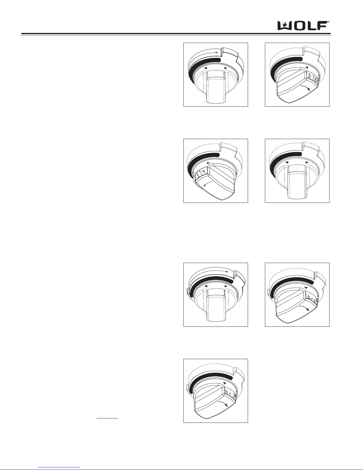
DDuuaall FFuueell RRaannggee
Operation Information
3-14
Convection Bake Mode
This mode combines heat from two convection elements with some heat from the hidden bake element.
Two convection fans circulate this heat within the oven
cavity. The added heat from the hidden bake element
make this mode ideal for pie baking.
To initiate Convection Bake Mode, turn oven control
knob bezel clockwise to dark area on dial marked
BAKE. (See Figure 3-24). Temperature is preset at
375°F (190°C). To change temperature, immediately
turn temperature readout knob to right to increase oven
temperature or to left to decrease oven temperature
setting. (See Figure 3-25 and 3-26). Oven will turn on
after 2 seconds or press ENTER key.
To exit Convection Bake Mode, turn oven knob bezel to
OFF.
NOTE: Always preheat for Convection Bake mode.
NOTE: Temperature probe may be used in this mode.
NOTE: Timer function may be used during this mode.
NOTE: The temperature display alternates between set
and actual oven temperatures during preheat.
NOTE: Temperatures below 150°F (65°C) are displayed by the word "Lo" in the oven knob display window during preheat.
NOTE: Oven will chime when oven preheat temperature has been achieved.
Convection Broil Mode
Intense radiant heat from broil element browns and
sears surface of the food. Both convection fans
circulate hot air around the food. This mode shortens
broiling times for thicker cuts of meat, fish and poultry.
The high heat browns the exterior and convection
keeps the interior moist and juicy.
To initiate Convection Broil Mode, turn oven control
knob bezel clockwise to dark area on dial marked
BROIL. (See Figure 3-28). Temperature is preset to
“br1 for 550°F (290°C). To change temperature from,
br1, immediately turn the temperature readout knob to
left to decrease oven setting to "br2" 450°F (230°C)Med Broil or "br3" 350°F (175°C)-Low Broil. (See
Figure 3-29 and 3-30). Oven will turn on after 2 seconds or press ENTER key. To exit Convection Broil
Mode, turn oven control knob to OFF.
NOTE: Timer function may be used during this mode.
NOTE: Never preheat for Convection Broil mode.
NOTE: Temperature probe may not
used in this mode.
B
R
O
I
L
B
A
K
E
R
O
A
S
T
O
F
F
B
A
K
E
B
R
O
I
L
375
LO
HI
Figure 3-24. Turn Control
Knob Bezel Clockwise to
Dark Area Marked BAKE
B
R
O
I
L
B
A
K
E
R
O
A
S
T
O
F
F
B
A
K
E
B
R
O
I
L
HI
LO
Figure 3-25. Increase
Preset Temperature, Turn
Knob to Right
B
R
O
I
L
B
A
K
E
R
O
A
S
T
O
F
F
B
A
K
E
B
R
O
I
L
HI
LO
Figure 3-26. Decrease
Preset Temperature, Turn
Knob to Left
B
R
O
I
L
B
A
K
E
R
O
A
S
T
O
F
F
B
A
K
E
B
R
O
I
L
Lo
LO
HI
Figure 3-27. Lo appears
in display window if tem-
perature is below 150°F
R
O
A
S
T
B
R
O
I
L
C
O
N
V
O
F
F
B
A
K
E
B
A
K
E
br1
LO
HI
Figure 3-28. Turn Control
Knob Bezel Clockwise to
Dark Area Marked BROIL
R
O
A
S
T
B
R
O
I
L
C
O
N
V
O
F
F
B
A
K
E
B
A
K
E
HI
LO
Figure 3-29. Turn Knob
to Right to change to br2.
R
O
A
S
T
B
R
O
I
L
C
O
N
V
O
F
F
B
A
K
E
B
A
K
E
HI
LO
Figure 3-30. Turn Knob
to Left to change to br3.
Page 33
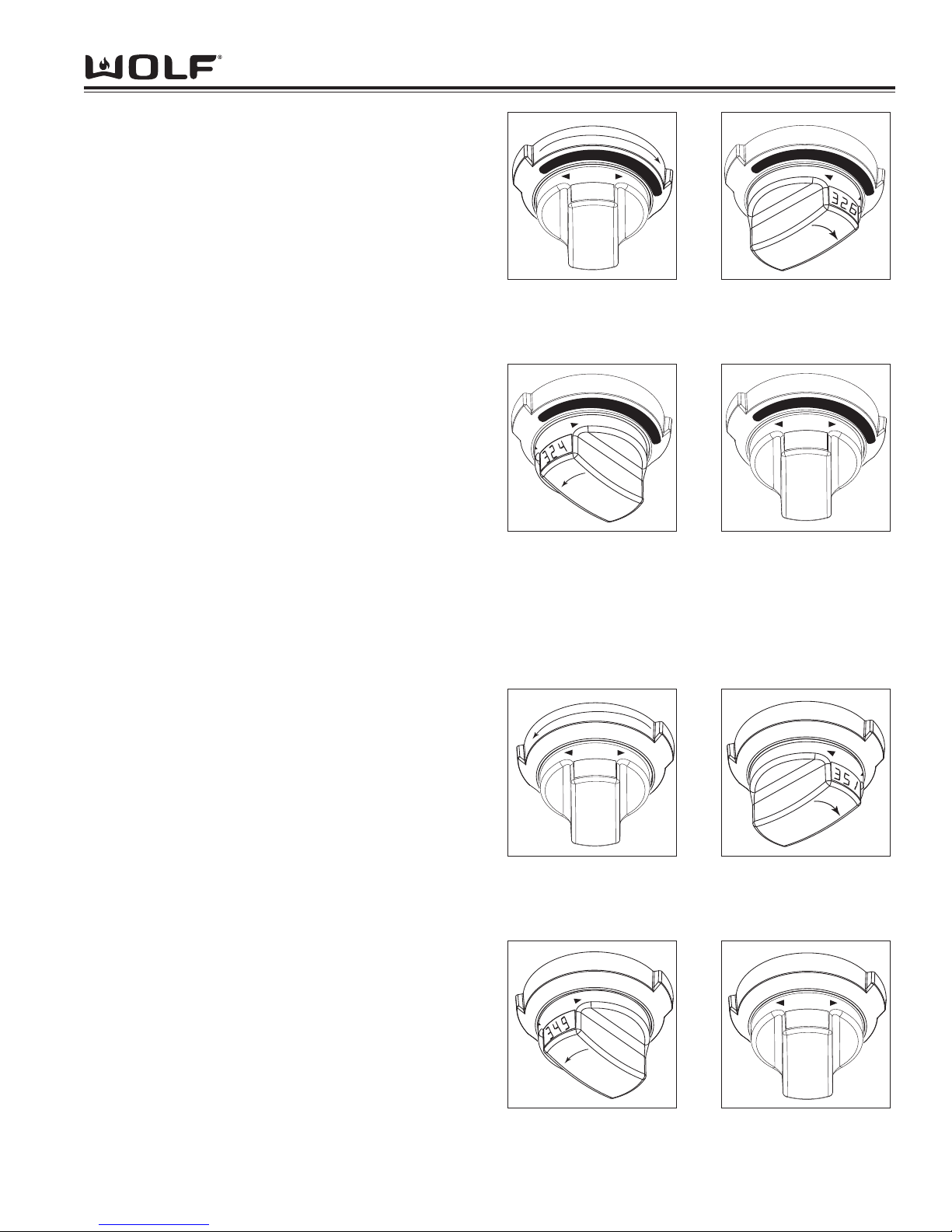
Operational Information
3-15
DDuuaall FFuueell RRaannggee
Convection Roast Mode
Heat from both convection fans, plus some heat
from the broil element, intensifies the convective and
radiant heating in this mode. This combination gently
browns the exterior and seals in juices making it perfect
for roasting tender cuts of beef, lamb, pork, and poultry.
To initiate Convection Roast Mode, turn oven control
knob bezel clockwise to dark area on dial marked
ROAST. (See Figure 3-31). Temperature is preset at
325°F (160°C). To change temperature, immediately
turn temperature readout knob to right to increase oven
temperature or to left to decrease oven temperature
setting. (See Figure 3-32 and 3-33). Oven will turn on
after 2 seconds or press ENTER key. To exit
Convection Roast Mode, turn oven knob bezel to OFF.
NOTE: Always preheat for Convection Bake mode.
NOTE: Temperature probe may be used in this mode.
NOTE: Timer function may be used during this mode.
NOTE: The temperature display alternates between set
and actual oven temperatures during preheat.
NOTE: Temperatures below 150°F (65°C) are displayed by the word "Lo" in the oven knob display window during preheat.
NOTE: Oven will chime when oven preheat temperature has been achieved.
Roast Mode
Both bake and broil elements are used to heat and
cycle to maintain temperature. Designed especially for
roasting the less tender cuts of meat that should be
covered, such as chuck roasts, lamb shanks, pot
roasts, stew meat.
To initiate Roast Mode, turn oven control knob bezel
counter clockwise to ROAST. (See Figure 3-35).
Temperature is preset at 350°F (175°C). To change
temperature, immediately turn temperature readout
knob to right to increase oven temperature or to left to
decrease oven temperature setting. (See Figure 3-36
and 3-37). Oven will turn on after 2 seconds or press
ENTER key
. To exit Convection Roast Mode, turn oven
knob bezel to OFF.
NOTE: Always preheat for Roast mode.
NOTE: Temperature probe may be used in this mode.
NOTE: Timer function may be used during this mode.
NOTE: The temperature display alternates between set
and actual oven temperatures during preheat.
NOTE: Temperatures below 150°F (65°C) are displayed by the word "Lo" in the oven knob display window during preheat.
NOTE: Oven will chime when oven preheat temperature has been achieved.
R
O
A
S
T
C
O
N
V
B
R
O
I
L
B
A
K
E
C
L
E
A
N
325
LO
HI
Figure 3-31. Turn Control
Knob Bezel Clockwise to
Dark Area Marked ROAST
R
O
A
S
T
C
O
N
V
B
R
O
I
L
B
A
K
E
C
L
E
A
N
HI
LO
Figure 3-32. Increase
Preset Temperature, Turn
Knob to Right
R
O
A
S
T
C
O
N
V
B
R
O
I
L
B
A
K
E
C
L
E
A
N
HI
LO
Figure 3-33. Decrease
Preset Temperature, Turn
Knob to Left
R
O
A
S
T
C
O
N
V
B
R
O
I
L
B
A
K
E
C
L
E
A
N
Lo
LO
HI
Figure 3-34. Lo Displayed
Until Temperature goes
above 150°.
R
O
A
S
T
B
A
K
E
B
R
O
I
L
S
T
O
N
E
C
L
E
A
N
O
F
F
350
LO
HI
Figure 3-35. Turn Control
Knob Bezel Counter
Clockwise to BAKE
R
O
A
S
T
B
A
K
E
B
R
O
I
L
S
T
O
N
E
C
L
E
A
N
O
F
F
HI
LO
Figure 3-36. Increase
Preset Temperature, Turn
Knob to Right
R
O
A
S
T
B
A
K
E
B
R
O
I
L
S
T
O
N
E
C
L
E
A
N
O
F
F
HI
LO
Figure 3-37. Decrease
Preset Temperature, Turn
Knob to Left
R
O
A
S
T
B
A
K
E
B
R
O
I
L
S
T
O
N
E
C
L
E
A
N
O
F
F
Lo
LO
HI
Figure 3-38. Lo Displayed
Until Temperature goes
above 150°.
Page 34
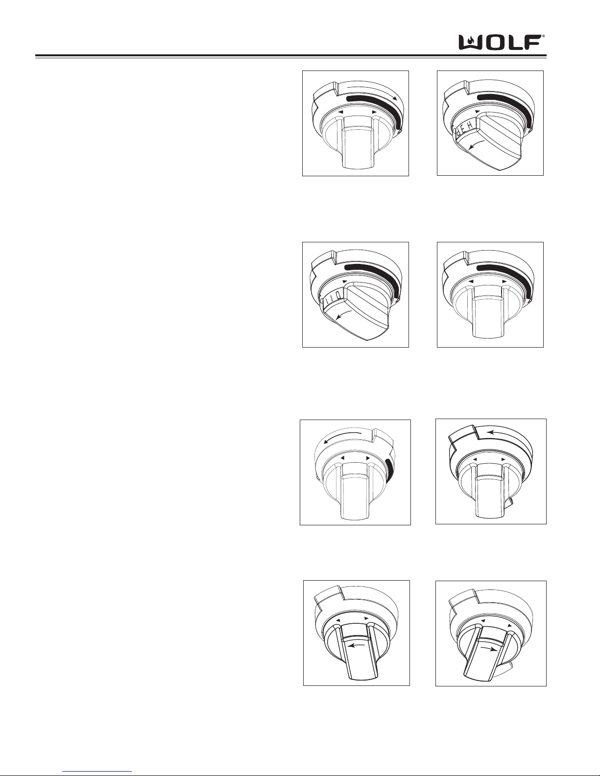
DDuuaall FFuueell RRaannggee
Operation Information
3-16
OVEN FEATURES
Dehydration Feature
This feature allows for slowly drying out food for preservation and other cooking uses. This requires an optional
accessory package.
To initiate Dehydration Feature, turn oven control knob
bezel clockwise to CONV. (See Figure 3-39). Now turn
control knob to left until “deH” shows in the control knob
display window. 170°F (77°C). (See Figure 3-40).
Then, release the temperature knob. Now, turn control
knob left or right to desired dehydration temperature.
(See Figure 3-41). Dehydration is between 110°F -
150°F (45°C - 65°C). To exit Dehydration Mode, turn
oven knob bezel clockwise to OFF.
NOTE: Preheat is not necessary for Dehydration feature.
NOTE: Optional accessory package, not supplied with
unit must be used.
Proof Mode (18” Cavity)
To activate PROOF Mode turn control knob counter
clockwise to PROOF and set temperature between
85°F and 110°F. (See Figure 3-43).
Proof Feature (30” and 36” Cavity)
How PROOF feature works: A combination of Broil,
Convection and Bake elements are used to heat and
balance the air to maintain temperature. This feature is
ideal for proofing bread dough. The oven does not
allow the temperature to be set above 110°F (43.3°C).
If the oven temperature is above 130°F(55°C), “HOT”
will be indicated on the control panel. The user should
open the oven door to allow the oven to cool down
below 120°F(50°C) to prevent from destroying the
yeast.
To initiate PROOF Feature, the oven must be OFF.
Place dough in oven-safe dish in oven. Turn oven
selector knob bezel counter clockwise to BAKE.
(See Figure 3-44).
Hold Oven Selector knob to left until “PrF” shows on the
knob. (See Figure 3-45). This will occur below 170°F
(77°C). Release the knob, then quickly turn knob to the
left or right and release to initiate PROOF.
NOTE: Oven temperature is preset at 85°F(29°C).
To change the temperature from 85°F(29°C), immediately turn the oven control knob to the right to increase
the oven temperature. (See Figure 3-46). Press
ENTER on the display panel or oven will turn on after 2
seconds by default. The temperature display alternates
between set temperature and "PrF". Turn oven selector
knob bezel to OFF to end this feature.
325
LO
HI
C
L
E
A
N
C
O
N
V
R
O
A
S
T
S
T
O
N
E
S
T
O
N
E
Figure 3-39. Turn Control
Knob Bezel Clockwise to
Dark Area Marked CONV
C
L
E
A
N
C
O
N
V
R
O
A
S
T
S
T
O
N
E
S
T
O
N
E
HI
LO
Figure 3-40. Turn and
HoldKnob to Left Until
“deH” Appears In Knob
Display and Release
Knob
C
L
E
A
N
C
O
N
V
R
O
A
S
T
S
T
O
N
E
S
T
O
N
E
HI
LO
Figure 3-41. Turn Knob
to Left or Right to Set
Desired Dehydration
Temperature
C
L
E
A
N
C
O
N
V
R
O
A
S
T
S
T
O
N
E
S
T
O
N
E
dEH
LO
HI
Figure 3-42. “deH” will
Alternate with the
Temperature in Display
5
0
3
LO
HI
A
S
B
A
K
E
O
F
F
R
O
B
R
O
I
L
B
A
K
E
Figure 3-44. Turn Control
Knob Bezel to BAKE
r
F
P
LO
HI
A
S
B
A
K
E
O
F
F
R
O
B
R
O
I
L
B
A
K
E
Figure 3-45. Turn and
Hold Control Knob to Left
until “PrF” is Displayed
1
1
0
A
LO
HI
S
B
A
K
E
O
F
F
R
O
B
R
O
I
L
B
A
K
E
Figure 3-46. Turn Control
Knob Left or Right to
Change Temperature
8
5
LO
HI
P
R
O
O
F
R
O
A
S
T
B
R
O
I
L
C
L
E
A
N
C
O
N
V
R
O
B
A
K
E
Figure 3-43. Turn Control
Knob Bezel counter
clockwise to PROOF
Page 35
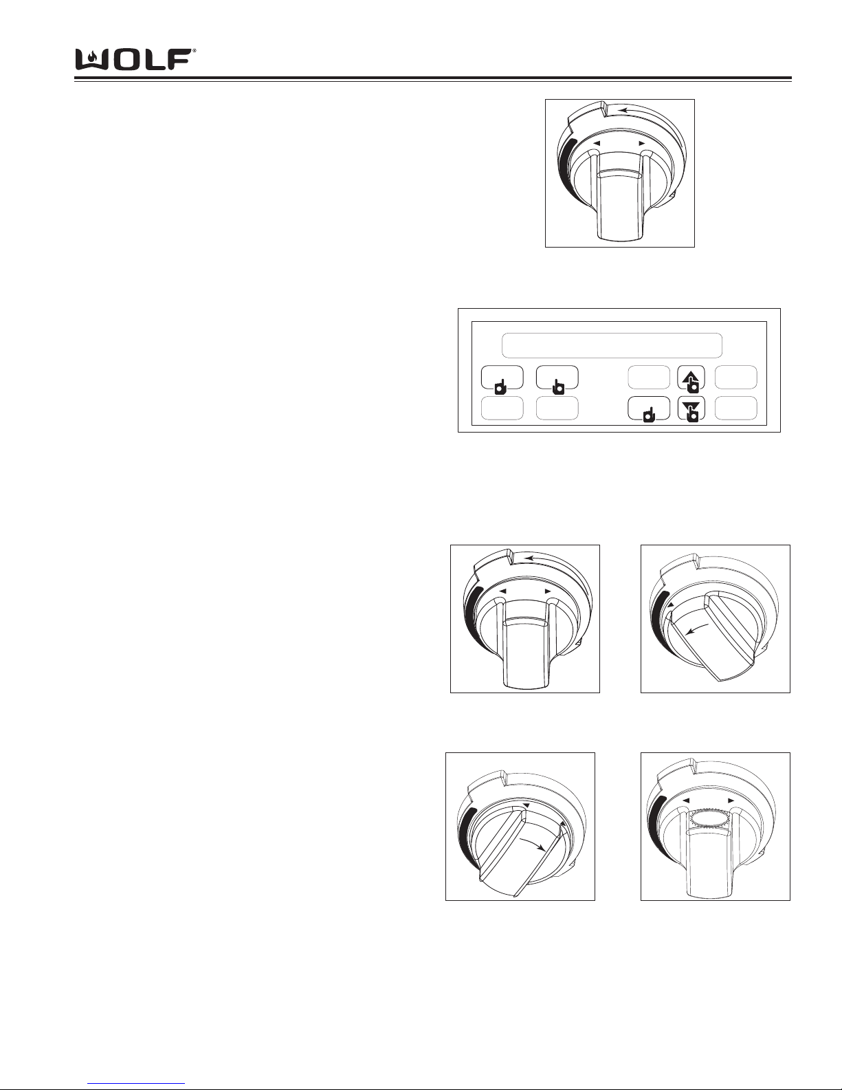
Operational Information
3-17
DDuuaall FFuueell RRaannggee
Delayed Start Feature
This feature controls the automatic timing of the oven’s
On and Off function. Set a cooking mode to start later
in the day and turn off when the cooking is complete or
set it to just to turn off at a preset time. See the Use &
Care Manual for additional information.
Set controls to start cooking later and automatically
turn off heat when finished.
To initiate Delayed Start Feature, turn oven control knob
bezel to the desired mode. Change preset temperature
if needed. (See Figure 3-47). Now, press COOK TIME
key. Then, press up or down arrow key on the display
panel to increase or decrease the desired cook time.
Next, press STOP TIME key. Then, press up or down
arrow key on the display panel to increase or decrease
the desired stop time. Now, press ENTER key. The
oven will appear as though it’s on. (See Figure 3-48).
The oven will turn on when clock time displays start
time. To exit Delayed Start Feature, turn oven control
knob bezel to OFF.
NOTE: Display appears as if the oven is on. One
chime will ring before the last minute of the cooking
time.
NOTE: Three chimes that repeat every 30 seconds
signal end of cooking time. The oven will turn itself off.
NOTE: Do not delay the start when preheating is critical to the cooking results.
NOTE: The time-of-day clock must display the correct
time prior to programming a timed activity.
Probe Feature
The probe measures internal temperature by measuring
the internal temperature of food without opening oven
door. It is a convenient and accurate way to achieve
perfect doneness regardless of the type, cut or weight
of food. Calculating a total cooking time by weight is no
longer necessary using this feature.
To initiate Probe Feature, preheat oven in desired
mode. Now, insert probe connector into receptacle,
inside oven cavity. Next, PROBE will appear on display
panel. Probe temperature is preset to 160°F (70°C).
(See Figure 3-49). To change temperature, immediately turn temperature readout knob to right to increase
probe temperature or to left to decrease probe temperature setting. (See Figure 3-50 and 3-51). Then, press
ENTER key or after 2 seconds oven will turn on by
default. Probe temperature will flash in knob display
when temperature has been reached.
(See Figure 3-52).
To exit, turn oven control knob bezel to OFF.
COOK
TIME
PROBE
CLOCK
ENTER
TIMER
CLEAR
STOP
TIME
OVEN
LIGHT
1:00
1
2
2
2
2
4
3:30
6:00
2
3
Figure 3-48. Press COOK TIME Key . Next, Press Arrow
Up or Down Key To Set Desired Cook Time. Then, Press
STOP TIME Key. Then, Press Arrow Up or Down Key To
Set Desired COOK TIme. Now, Press ENTER Key.
B
A
K
E
B
R
O
I
L
R
O
A
S
T
B
R
O
I
L
O
F
F
B
A
K
E
B
R
O
I
L
5
0
3
LO
HI
Figure 3-47. Set Control Knob Bezel to Desire Mode and
Temperature
B
A
K
E
B
R
O
I
L
R
O
A
S
T
B
R
O
I
L
O
F
F
B
A
K
E
B
R
O
I
L
LO
HI
160
Figure 3-49. Probe
Temperature Preset to
160°F
B
A
K
E
B
R
O
I
L
R
O
A
S
T
B
R
O
I
L
O
F
F
B
A
K
E
B
R
O
I
L
HI
LO
1
4
5
Figure 3-50. Turn Control
Knob Bezel to Set
Desired Temperature
HI
LO
B
A
K
E
B
R
O
I
L
R
O
A
S
T
B
R
O
I
L
O
F
F
B
A
K
E
B
R
O
I
L
1
6
5
Figure 3-51. Turn Control
Knob Bezel to Set
Desired Temperature
B
A
K
E
B
R
O
I
L
R
O
A
S
T
B
R
O
I
L
O
F
F
B
A
K
E
B
R
O
I
L
LO
HI
160
Figure 3-52. Probe
Temperature will Flash
when Temperature is
Reached
Page 36
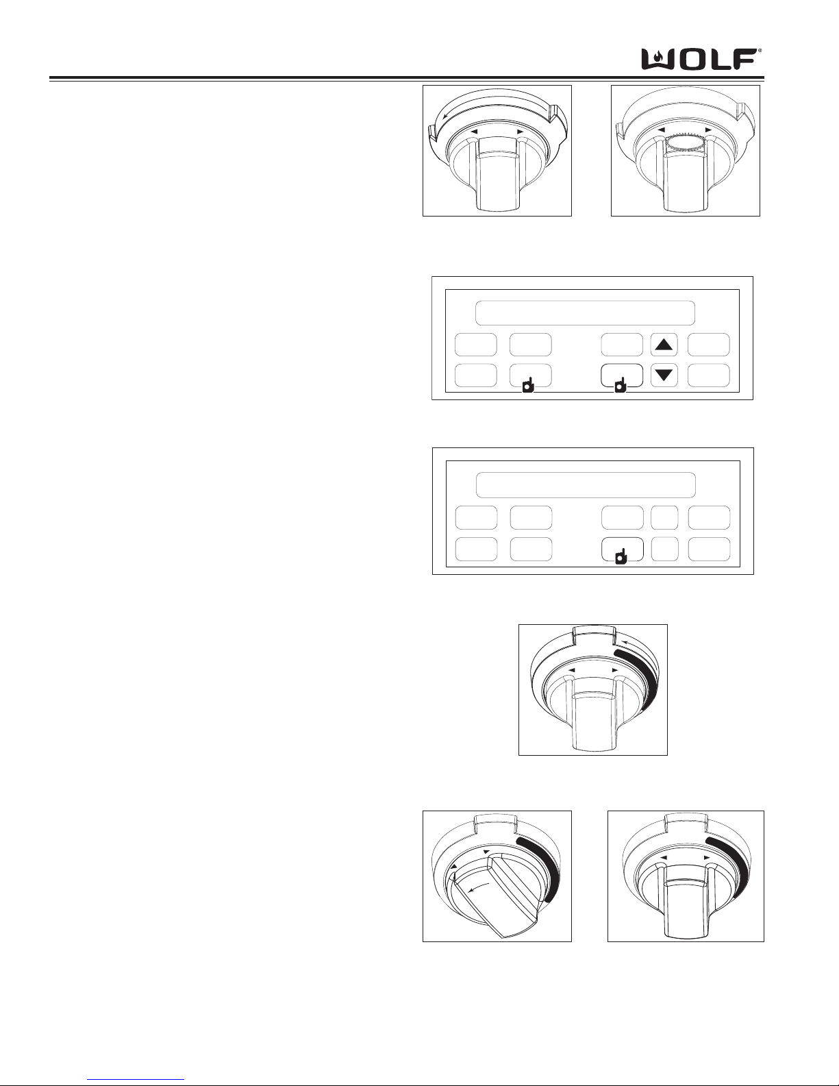
DDuuaall FFuueell RRaannggee
Operation Information
3-18
Sabbath Feature
This feature allows for baking or keeping food warm
while still adhering to the "no work" requirements on
religious Sabbath days.
To initiate Sabbath Feature, first add food to the oven.
Now, turn oven control knob bezel to either BAKE or
ROAST mode. (See Figure 3-53). Next, change preset
temperature if needed. Then, press OVEN LIGHT key
to turn oven lights on or off. (See Figure 3-55). Now,
press and hold ENTER key on display panel for 5 seconds. (See Figure 3-55). Oven chimes twice and the
word “SAb” appears in the display window on the oven
temperature control knob. (See Figure 3-54). To exit
Sabbath Feature, turn oven knob bezel to OFF.
NOTE: Oven remains on until this mode is cancelled.
Self-Clean Feature
The oven is heated in graduating steps to a preset high
temperature. During this process, food soil is burned
off leaving some white ash residue. For safety purposes, the door automatically locks during cleaning and
unlocks when the cavity has cooled completely.
To initiate Self-clean Feature, first turn oven control
knob bezel to CLEAN. (See Figure 3-57). Now, press
ENTER key on the control panel or turn the oven temperature control knob bezel in either direction until
"CLn" appears in temperature readout knob display window. The oven automatically sets for 4 hours. (See
Figure 3-56 ). Self-clean feature is now enabled and
“CLn” will be displayed in the oven control knob display
window. (See Figure 3-58A and 3-58B). To exit SelfClean Feature, turn oven knob bezel to OFF.
NOTE: The door gasket is important for a good seal.
Do not hand clean, rub, puncture, or remove.
NOTE: Oven door will remain locked until temperature
inside has cooled to below 300°F (150°C).
NOTE: Delayed Start feature can be programmed in
this feature.
NOTE: Oven racks, broiler pan, any utensils stored in
oven must be removed from oven cavity before selfcleaning.
NOTE: Units starting with serial number 16000000 the
rack guides must also be removed.
NOTE: Model DF48 and DF60 only one cavity can be
cleaned at one time.
NOTE: Model DF48 and DF60 If one cavity is being
self-cleaned the other cavity cannot be used for cooking.
LO HI
---
C
L
E
A
N
C
O
N
V
R
O
A
S
T
S
T
O
N
E
R
O
A
S
T
B
R
O
I
L
B
R
O
I
L
Figure 3-57. Turn Control
Knob Bezel Counter
Clockwise to CLEAN
LO
HI
-
-
-
C
L
E
A
N
C
O
N
V
R
O
A
S
T
S
T
O
N
E
R
O
A
S
T
B
R
O
I
L
B
R
O
I
L
Figure 3-58A. Turn Knob
to Left or Right, “CLn”
will Display
COOK
TIME
PROBE
CLOCK
ENTER
TIMER
CLEAR
STOP
TIME
OVEN
LIGHT
1:00
54
Figure 3-55. Press and Hold ENTER key to Set Oven to
Sabbath.
1
R
O
A
S
T
B
A
K
E
B
R
O
I
L
S
T
O
N
E
C
L
E
A
N
O
F
F
350
LO
HI
Figure 3-53. Turn Control
Knob Bezel Counter
Clockwise to ROAST
R
O
A
S
T
B
A
K
E
B
R
O
I
L
S
T
O
N
E
C
L
E
A
N
O
F
F
SAb
LO
HI
Figure 3-54. The letters
“SAb” appear in the knob
display.
L
n
C
LO HI
C
O
N
V
R
O
A
S
T
S
T
O
N
E
R
O
A
S
T
B
R
O
I
L
B
R
O
I
L
C
L
E
A
N
Figure 3-58B. Turn
Control Knob Bezel
Counter Clockwise to
BAKE
COOK
TIME
PROBE
CLOCK
ENTER
TIMER
CLEAR
STOP
TIME
OVEN
LIGHT
4:00
4:00
12:00
P
1
Figure 3-56. Press ENTER key. Automatically Sets for 4
Hours
Page 37
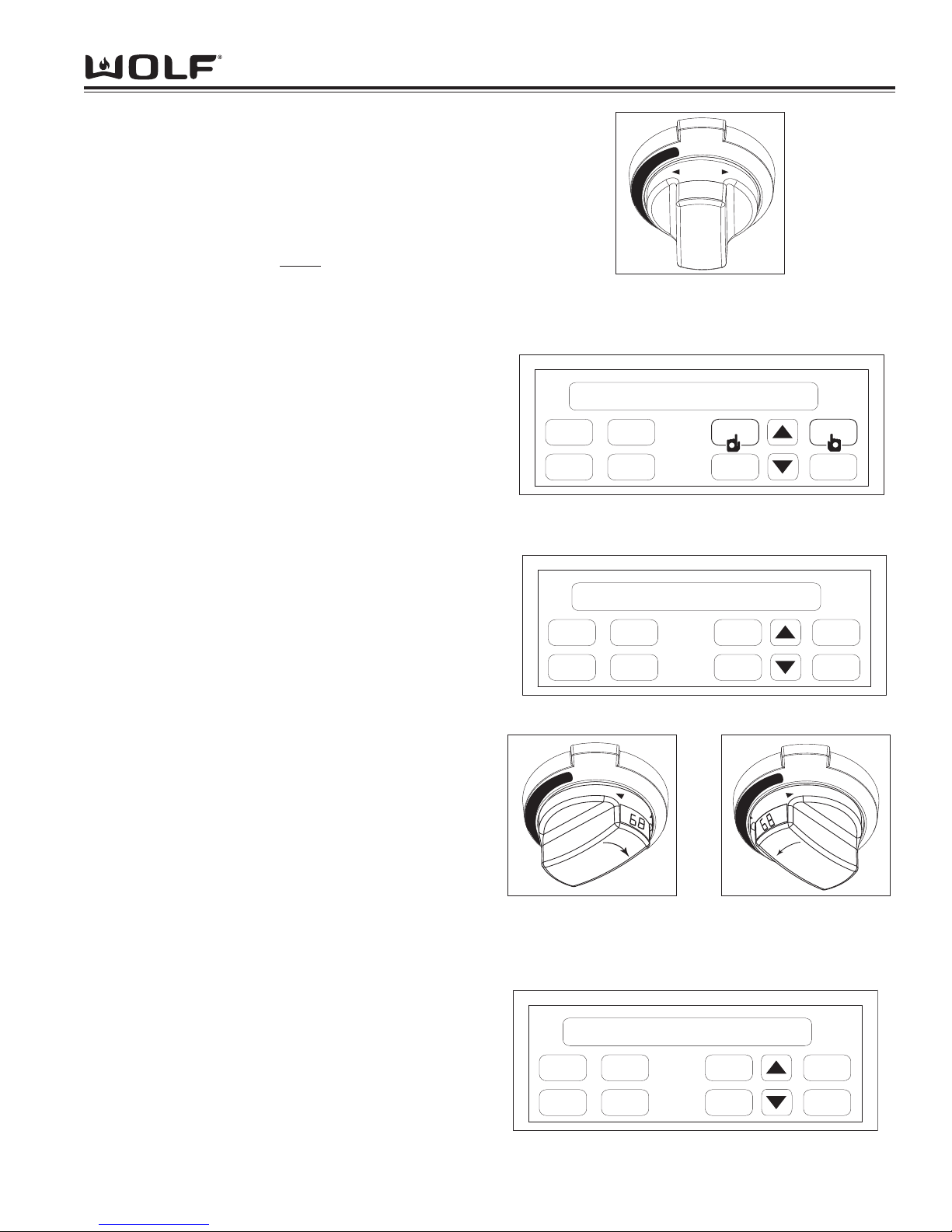
Operational Information
3-19
DDuuaall FFuueell RRaannggee
DIAGNOSTIC MODE
Diagnostic Mode allows the Service Technician to
inspect the functionality of the Oven Controller and
Relay boards. Entering a key combination on the display panel will allow the Service Technician to enter
Diagnostic Mode.
In Diagnostic Mode the last seven
errors that have
occurred to the oven controlling all the relays on the
relay board and controller feedback of temperature and
switches will be displayed.
The Electronic Control Housing will display last error
code recorded in the Cook Time digit area, with Stop
Time digits displaying the number that the error was
recorded, number 1 being the most recent. The software version will be displayed in the Time of Day digits
and current oven cavity temperature will be shown in
the display window of the Oven Temperature Control
Knob.
Initiating Diagnostic Mode
To initiate Diagnostic Mode, oven control knob bezel
must be in the OFF position. Now, press and hold
CLOCK key and TIMER key for 3 seconds. (See
Figure 3-60 ). The ambient cavity temperature will be
displayed in the temperature readout knob. Now, turn
the oven temperature readout knob to the right seven
separate times, this will toggle from error code 1 thru 7.
(See Figure 3-62 ). To return to error code number
one, turn oven temperature readout knob to the left
seven separate times. (See Figure 3-63 ). The software version will be displayed in the hours and minutes
display of the clock. (See Figure 3-64 ).
NOTE: Once diagnostic mode is entered, there is a 2
minute time out, which is restarted each time a key is
pressed.
To clear error codes once unit has been fixed, press the
CLEAR key.
To exit Diagnostic Mode, press the ENTER key.
COOK
TIME
PROBE
CLOCK
ENTER
TIMER
CLEAR
STOP
TIME
OVEN
LIGHT
1:00
1
2
1
Figure 3-60. Press and Hold CLOCK and TIMER Key
LO
HI
O
F
F
B
A
K
E
B
R
O
I
L
B
A
K
E
B
R
O
I
L
R
O
A
S
R
O
A
S
T
Figure 3-59. Control
Knob Bezel Must be in
OFF Position
O
F
F
B
A
K
E
B
R
O
I
L
B
A
K
E
B
R
O
I
L
R
O
A
S
R
O
A
S
T
HI
LO
Figure 3-62. Turn Knob
to Right Seven Separate
Times to Toggle thru
Error Codes
O
F
F
B
A
K
E
B
R
O
I
L
B
A
K
E
B
R
O
I
L
R
O
A
S
R
O
A
S
T
HI
LO
Figure 3-63. Turn Knob
to Left Seven Separate
Times to Toggle thru
Error Codes
COOK
TIME
PROBE
CLOCK
ENTER
TIMER
CLEAR
STOP
TIME
OVEN
LIGHT
r100
Err
00
1
P
Figure 3-61. Error Code and Software Version Display
COOK
TIME
PROBE
CLOCK
ENTER
TIMER
CLEAR
STOP
TIME
OVEN
LIGHT
r100
Err
00
7
P
Figure 3-64. Error Code Display
Page 38
DDuuaall FFuueell RRaannggee
Operation Information
3-20
ERROR INDICATORS
Error codes can give a visual and audible alarm. The visual indication will be “Err” displayed in the Cook Time digits
and the number or letter of the error code will be displayed in the Stop Time digits of the Electronic Control Housing.
The Oven Temperature Readout Knob will also show “Err” in the display window. The last seven errors will be
stored in the EEPROM for recall when in diagnostic mode.
ERROR CODE POSSIBLE CAUSE TEST / ACTION
ERROR CODE CHART
Figure 3-65. Error Code Chart
01
02
03
04
07
08
09
0B
0C
0E
Door Lock or Unlock Switches not sensed
within 60 seconds while driving the door
lock motor
Over temperature occurs when the oven
reaches a temperature of 630 °F for an
unlocked door and 950°F for a locked door
Open circuit detected on RTD Oven Sensor
Shorted circuit detected on the RTD Sensor
SPI Communication lost from ECH to the
Control Board as reported by Control Board
EEPROM checksum is incorrect. Checked
at power up
Meat probe being sensed as shorted
Analog to Digital error during calibration
phase
Communication lost with oven controller
Power relay shorted, sensed as closed
when should be open
Failure of element circuit
Failure of relay drive circuitry
Perform motorized door lock test procedure in
diagnostic mode
Ohm door lock switches. Replace MDL (Motor
Door Lock) Assembly if defective
Ohm RTD sensor, replace if defective. If RTD
good replace oven controller.
Ohm RTD sensor, replace if defective. If RTD
good replace oven controller.
Ohm RTD sensor, replace if defective. If RTD
good replace oven controller.
Code reflects that the ECH cannot fine the
Control Board. Replace cable first. Replace
ECH if replacing cable does not correct problem
Replace oven controller
Initiated diagnostic mode and check meat
probe. Ohm meat probe, check reading with
Tech Data
Replace oven controller
Replace oven controller
Replace relay board
Replace relay board
Replace relay board
Page 39
Operational Information
3-21
DDuuaall FFuueell RRaannggee
TESTING THE OVEN RELAY BOARD
Element Testing
First access diagnostic mode. Once in diagnostic mode, the technician can turn the oven control knob bezel to activate an element. The element relay and the double line breaker(dlb) will close to complete a 240/208 VAC circuit
through a specific element. If the oven controller detects the current running through the closed circuit, the **CFH light
will be illuminated.
NOTE: Diagnostic Mode will end 2 minutes after last key stroke or when the CLEAR key is pressed.
Figure 3-66. Element Testing Chart
** Call For Heat
Turn Bezel (Cooking Mode) Relay(s) Activated Response
Stone
(Use “PROOF” for 18” Cavity)
Clean
Conv
Conv Roast
Conv Broil
Conv Bake
Left Convection Element
Right Convection Element
Bake Stone Element
(must be plugged in)
Inner Bake Element
Broil Element
Outer Bake Element
**CFH Indicator Light Illuminates
**CFH Indicator Light Illuminates
**CFH Indicator Light Illuminates
**CFH Indicator Light Illuminates
**CFH Indicator Light Illuminates
**CFH Indicator Light Illuminates
RTD Testing
First access Diagnostic Mode. Once in diagnostic mode, the RTD temperature is shown in display window of temperature control knob. If the RTD is open, “Err 03” will be shown in the display of the electronic control housing. If the
RTD is shorted, “Err 04” will be shown in the display of the electronic control housing.
NOTE: Diagnostic mode will end 2 minutes after last key stroke or when the ENTER key is pressed.
Probe Testing
First access Diagnostic Mode. Next, press the PROBE key (this will switch the readout to probe temperature as shown
in the display window of the temperature control knob). If the probe has not been inserted, “out” will be shown as the
probe temperature in the display window of the temperature control knob. If the probe is shorted, “Err 09” will be shown
in the display of the electronic control housing.
NOTE: Diagnostic Mode will end 2 minutes after last key stroke or when the ENTER key is pressed.
Page 40
DDuuaall FFuueell RRaannggee
Operation Information
3-22
Fans and Motors
First access diagnostic mode. Once in diagnostic mode, the technician can turn the oven control knob bezel or
press a key on the Electronic Control Housing to activate a fan or a motor. The fan and motor relays will close to
complete a 120 VAC circuit through a specific fan or motor. If the oven controller detects the functionality through
switches, the **CFH indicator light will be illuminated.
NOTE: Diagnostic mode will end 2 minutes after last key stroke or when the ENTER key is pressed.
Figure 3-67. Fan and Motor Testing Chart
Turn Bezel
(Cooking Mode)
or
Press Key on Electronic
Control Housing
Relay(s) Activated
Response
Broil
Roast
Bake
Cook Time
Stop Time
Clock
NOTE: For DF48 and
DF60 “CLOCK” cycles
left MDL. Use “TIMER”
to cycle right MDL.
Probe
Clear
Enter
Right Convection Fan
Left Convection Fan
and 18” cavity convection fan
Oven Light
Lo Cooling Fan
High Cooling Fan
Motor Door Lock
(MDL)
Probe
Right Convection Fan ON
Left Convection Fan ON
Oven Light Turns On
Cooling Fan ON at Low Speed
Cooling Fan ON at High Speed
“P” Icon Appears
No Icon in Display
“A” Icon Appears
Meat Probe Temperature is
Shown in Display Window of
Temperature Control Knob
Clears All Stored Errors from
EEPROM
Exits Diagnostic Mode
Action
Right Convection Fan
Turns ON
Left Convection Fan
Turns ON
Cooling Fan ON
Cooling Fan ON
MDL Switch in Closed
Position
MDL Switch in
Transition
MDL Switch in open
Position
Page 41

Component Access & Removal
4-1
DDuuaall FFuueell RRaannggee
SECTION 4
COMPONENT
ACCESS AND REMOVAL
Page 42
DDuuaall FFuueell RRaannggee
Component Access & Removal
4-2
COMPONENT ACCESS AND REMOVAL
This section explains how to access and remove components from a Wolf Dual Fuel Range. Depending on which
component you are going to access or remove in the following sections, you may have to remove other components
first. Refer to the appropriate section in this manual that explains how to access and remove those various components. When reassembling, just reverse the steps that were used to access and remove the components.
NOTE: Before attempting to access or remove any components from a Wolf Appliance, take note of the following
warnings.
TO AVOID SERIOUS BURNS AND/OR EXPLOSIONS, KEEP COMBUSTIBLES AWAY FROM THE APPLIANCE
WHENEVER A FLAME IS PRESENT. REMEMBER THAT SURFACES AND COMPONENTS GET HOT
DURING THE USE OF THE APPLIANCE.
TO AVOID ELECTRICAL SHOCK, POWER TO THE UNIT MUST BE DISCONNECTED WHENEVER ACCESSING
AND/OR REMOVING COMPONENTS POWERED BY ELECTRICITY OR COMPONENTS NEAR OTHER
ELECTRICAL COMPONENTS.
TO AVOID HAZARDOUS EXPLOSION OR GAS LEAKS, GAS TO THE UNIT MUST BE TURNED OFF
AT THE GAS SUPPLY SOURCE WHENEVER ACCESSING AND/OR REMOVING COMPONENTS.
TO ENSURE PROPER BURNER OPERATION, THE O-RINGS
MUST BE REPLACED ANY TIME THE UNITS IS
DISASSEMBLED FOR ANY REASON.
WHEN REASSEMBLING GAS SUPPLY LINE TO REGULATOR, ONLY PIPE THREAD COMPOUND SHOULD
BE USED. DO NOT
USE TEFLON TAPE TO SEAL GAS PIPE CONNECTIONS.
Page 43
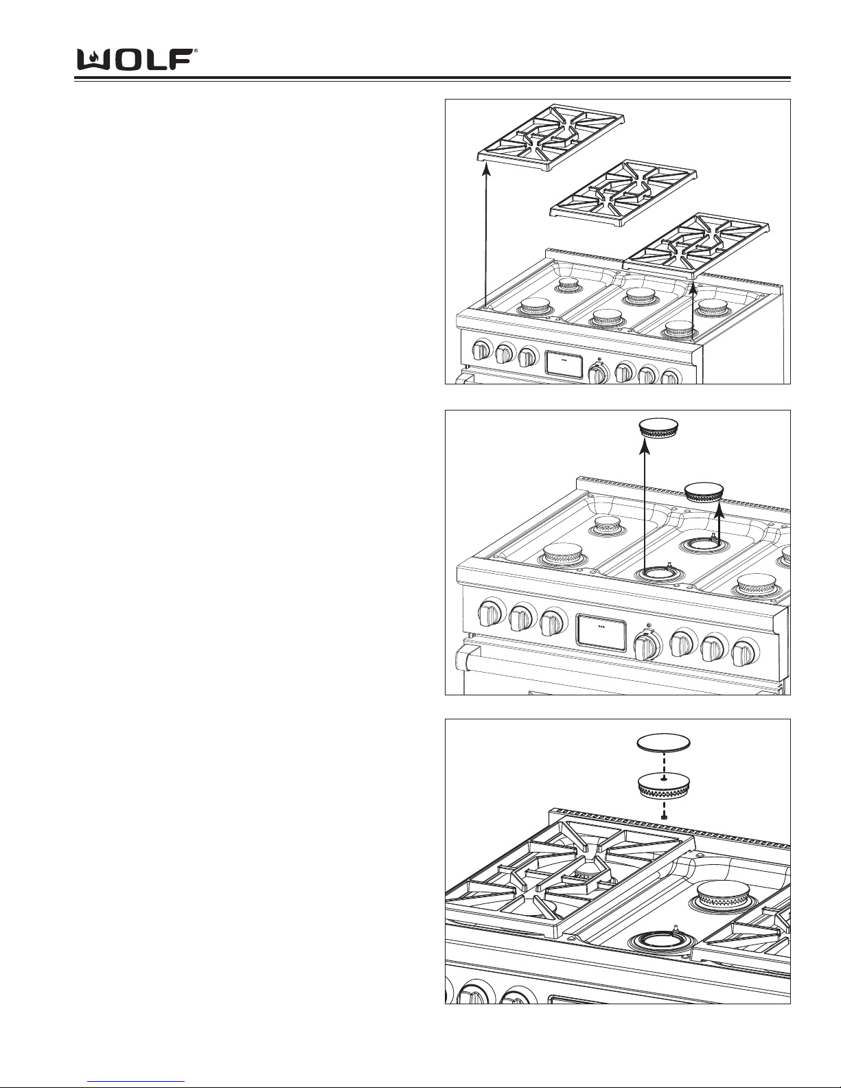
Component Access & Removal
4-3
DDuuaall FFuueell RRaannggee
Figure 4-1. Surface Grate Removal
Surface Burner Components
(PTS 17000000)
Surface Burner Grate, Burner Head, Burner Cap,
Venturi, Inner Distribution Ring, Igniter, Burner Pan,
Outer Distribution Ring, Jet Holder, Deflector
Shield, Spark Module, Burner Support and Surface
Burner Orifices
Surface Burner Grate Removal (PTS 17000000)
The surface grate is a low profile, porcelainized cast
iron grate that is designed for a close fit. To remove the
surface grate, lift straight up and off of the top pan.
(See Figure 4-1)
Burner Head with Cap Removal (PTS 17000000)
The burner head consists of a top and bottom layer of
holes. When main burner heat is required, the gas
travels through the main burner orifice hood (mounted
to the jet holder), then through the venturi to the burner
head and then out the top layer of holes. When simmer
heat is required, the gas travels through the simmer orifice hood (located on the side of the outer distribution
ring), up through the outer portion of the inner distribution ring, then to the bottom layer of holes on the burner
head.
To remove the burner head, first remove the burner
grates. Then, lift the burner head off of the inner distribution ring. (See Figure 4-2)
Burner Cap Removal (PTS 17000000)
The burner cap can be replaced separately from the
burner head if cap gets damaged.
To remove burner cap, turn burner head over so nut on
underside is visible. Then, use a wrench to loosen nut
and remove. Now, remove cap from the burner head.
(See Figure 4-3)
Figure 4-2. Burner Head Removal
Figure 4-3. Burner Cap Removal
Page 44
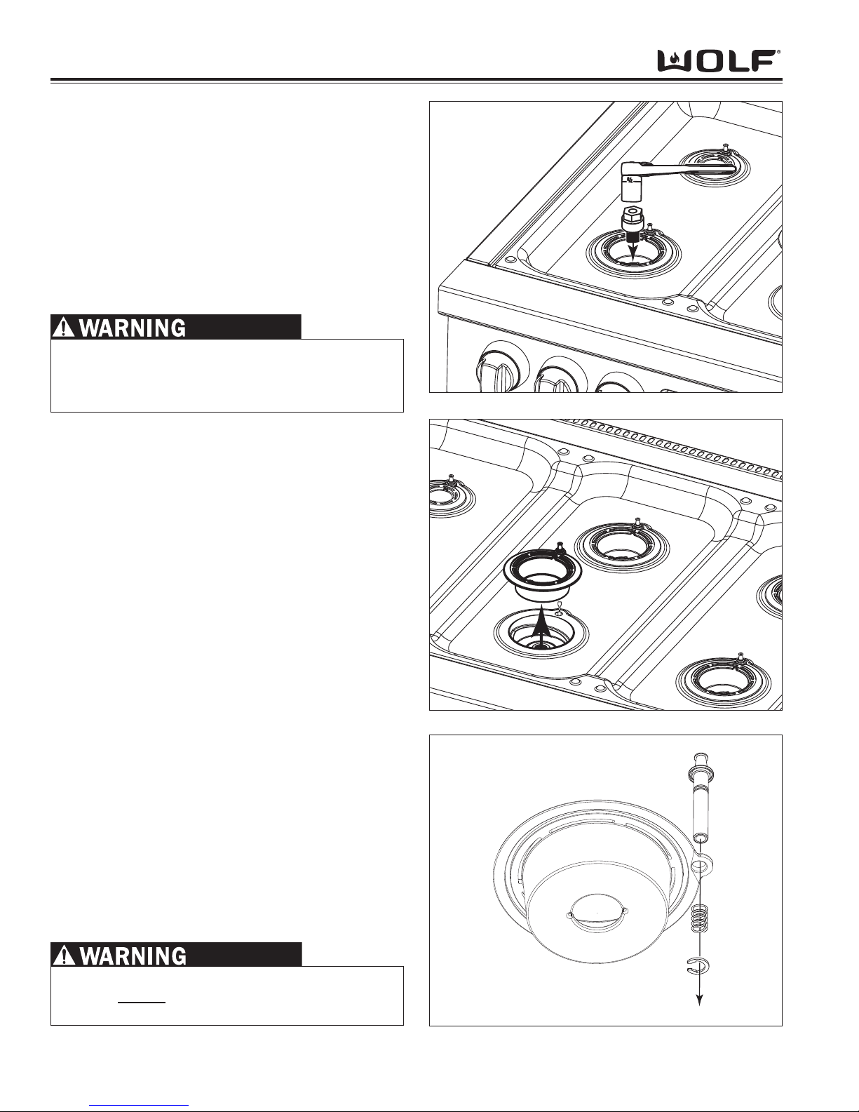
DDuuaall FFuueell RRaannggee
Component Access & Removal
4-4
Figure 4-4. Venturi Removal
Figure 4-6. Igniter Removal
Figure 4-5. Outer Distribution Ring Removal
Venturi Removal (PTS 17000000)
The brass venturi mounts through the inner distribution
ring and is threaded to the jet holder. There are two
sizes of venturi. One size is for the large 15,000 BTU
burners. The other size is for the smaller 9,200 BTU
burners. The threads on the venturi are different for the
large and for the small. They will only thread back into
the appropriate sized jet holder.
To remove the venturi, first remove the burner head
with cap and then extract the venturi using a 7/8 inch
socket wrench from the jet holder. (See Figure 4-4)
Inner Distribution Ring Removal (PTS 17000000)
The inner distribution ring routes the gas from the simmer orifice hood to the simmer holes located in the
burner head.
To remove the inner distribution ring, first, remove the
venturi. Then, lift the inner distribution ring from the
cooktop pan and discard the O-ring which is mounted in
a groove in the underside of the inner distribution ring.
The O-ring provides the seal between the cooktop pan
and the inner distribution ring. Now, unplug the igniter
lead wire and use a small piece of black tape to secure
the lead wire to the top pan.
(See Figure 4-5)
Igniter Removal (PTS 17000000)
The surface burner igniter is inserted down through the
inner distribution ring. It is held in place by a spring
and clip.
To remove the igniter, the burner head and venturi will
need to be removed. Now, lift the inner distribution ring
from the top pan, unplug igniter lead and tape it to the
top pan. Then, push the spring up slightly and use pliers to remove the clip. Now, slide the spring off the
igniter and pull the igniter up and out of inner distribution ring. (See Figure 4-6)
WHEN REINSTALLING VENTURI USE TORQUE
WRENCH TO TIGHTEN TO 100 INCH/LBS. OVER
TIGHTENING WILL DAMAGE UNIT AND GAS
LEAKS MAY OCCUR.
TO ENSURE PROPER BURNER OPERATION, THE
O-RINGS
MUST BE REPLACED ANY TIME THE
UNITS IS DISASSEMBLED FOR ANY REASON.
Page 45
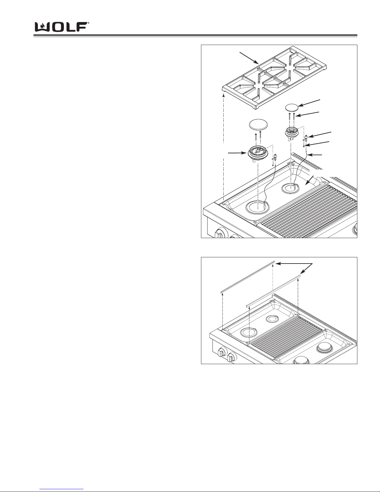
Component Access & Removal
4-5
DDuuaall FFuueell RRaannggee
Surface Burner Components
(SWS 17000000)
Burner Grate and Burner Assembly (SWS 17000000)
The burner grate locates on raised dimples formed on
the burner pan. The burner assemblies have screws
that pass through the assemblies, then thread into the
orifice holder located under the burner pan. Burner
caps are then placed over the burner assembly.
To remove the burner assembly, (See Figure 4-6A)
1. Remove burner grate from unit.
2. Remove burner caps from burner assembly.
3. Extract the two screws securing burner assembly to
orifice holder.
4. Lift assembly off burner pan and remove wire lead
from spark ignitor.
5. To remove spark ignitor from burner, extract screw
from underside of burner assembly and separate.
Burner Pan and Trim Moldings (SWS 17000000)
There are two “L” shaped trim moldings for each burner
pan that run from front to back of the unit. One moldings fits between the outer side assembly and the burner pan, the other molding fits between burner pans and
grill grate or french cook top assembly, depending on
the model.
To remove the burner pan,
1. Remove front and rear burner assemblies.
2. Remove trim moldings from each side of burner
pan. (See Figure 4-6B)
3. Lift burner pan out of unit.
Figure 4-6A. Burner Assembly Removal
Figure 4-6B. Trim Moldings
Burner Grate
Burner Cap
Screw
Screws
Burner
Assembly
Ignitor
Wire Lead
Burner Pan
Trim Moldings
Page 46
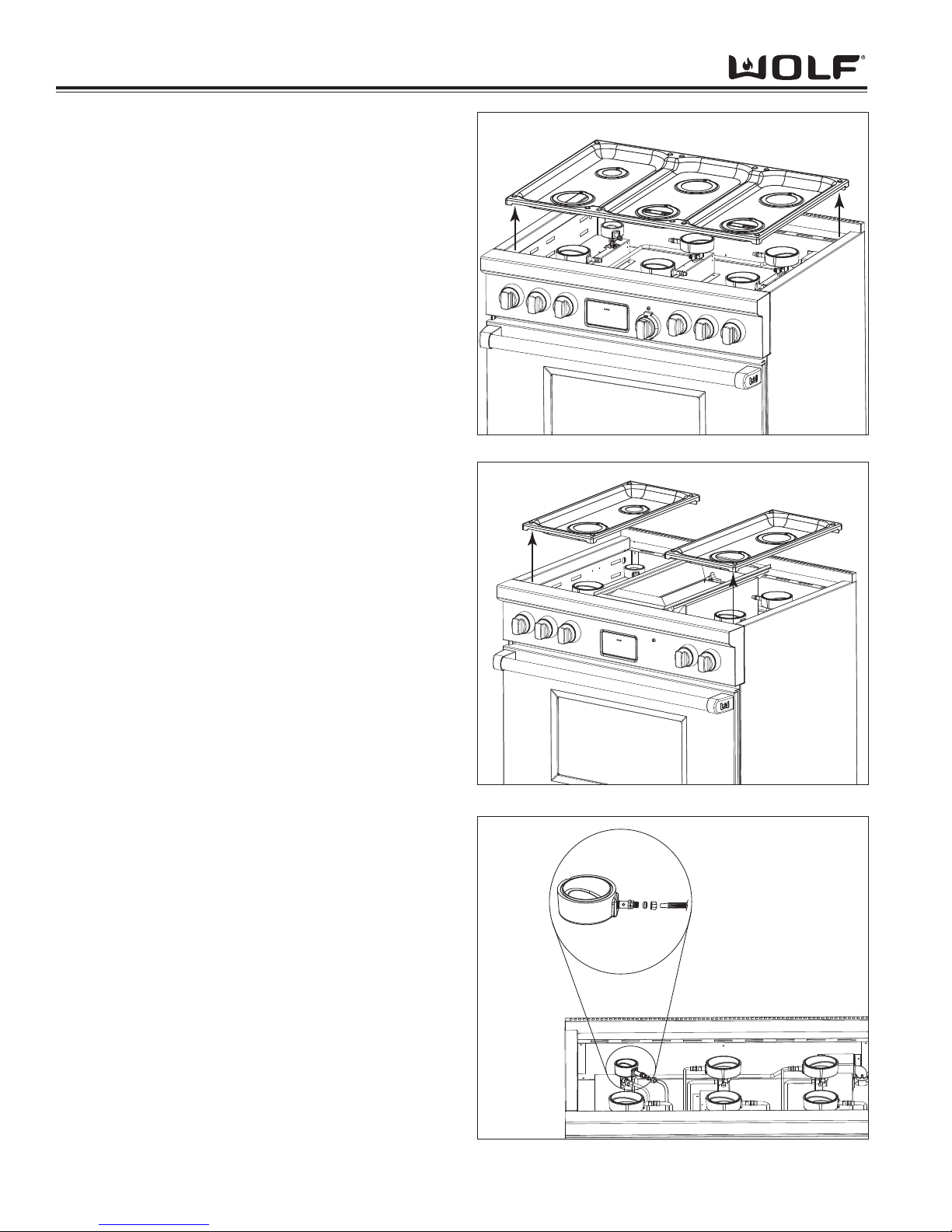
DDuuaall FFuueell RRaannggee
Component Access & Removal
4-6
Figure 4-7. Six Burner Top Pan Removal
Burner Pan - 6 Burner Removal
In order to remove the burner pan you will need to
remove the grates, burner heads w/caps, venturis, igniter lead wires and inner distribution rings. Now the
burner pan can be lifted straight up and off. (See
Figure 4-7)
Burner Pan - 2 Burner Removal
In order to remove the burner pan you will need to
remove the grate, burner heads w/caps, venturis, igniter
lead wires and inner distribution rings. Now the burner
pan can be lifted straight up and off. (See Figure 4-8)
Outer Distribution Ring Removal (PTS 17000000)
The outer distribution ring routes the gas from the main
burner orifice hood to the main burner holes at the top
of the burner head.
To remove the outer distribution ring, remove the
grate(s), burner head(s) w/cap(s), venturis, igniter lead
wires, inner distribution rings and burner pan. Then,
using wrenches, disconnect the flexible gas tube that is
mounted to the outer distribution ring connector. Next,
lift the outer distribution ring from the jet holder. (See
Figure 4-9) There are two different sized O-rings,
which sit in grooves in the outer distribution ring.
Figure 4-8. Four Burner Top Pan Removal
Figure 4-9. Outer Distribution Ring Removal
Page 47
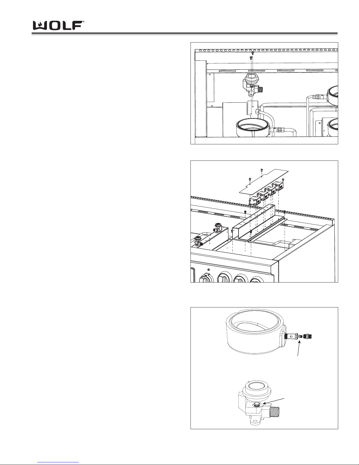
Component Access & Removal
4-7
DDuuaall FFuueell RRaannggee
Simmer
Orifice
Main
Orifice
Figure 4-12. Orifice Locations
Jet Holder Removal (PTS 17000000)
The jet holder is mounted to the burner support on the
bottom of the burner box. The main burner orifice is
threaded into the jet holder as well as the venturi.
To remove the jet holder, remove the grate(s), burner
head(s) w/cap(s), venturis, igniter lead wires, inner distribution ring(s), burner pan and outer distribution rings.
Then, disconnect the flexible gas tube that is mounted
to the jet holder. Now, extract the screws which secure
the jet holder to the burner support and lift the jet holder
off. (See Figure 4-10)
Deflector Shield Removal (PTS 17000000)
The deflector shield protects the spark modules and
wiring from spillage that may occur.
To remove the deflector shield, remove the grate(s),
burner head(s) w/cap(s), venturis, igniter lead wires,
inner distribution rings, burner pan, outer distribution
rings and jet holders. Now, extract the screws which
secure it to the burner support and remove. (See
Figure 4-11)
Spark Module Removal (PTS 17000000)
To remove the spark module, remove the grate(s), burner head(s) w/cap(s), venturis, igniter lead wires, inner
distribution rings, burner pan, outer distribution rings
and deflector shield. Now, disconnect the wiring. Then,
extract the screws which secure it to the burner support
and remove. (See Figure 4-11)
Burner Support Removal (PTS 17000000)
The burner support is mounted to the bottom of the
burner box and acts as a spacer to keep the surface
burner components at the proper height.
To remove the burner support, remove the grate(s),
burner head(s) w/cap(s), venturis, igniter lead wires,
inner distribution rings, burner pan, outer distribution
rings, jet holders, deflector shield and spark module(s)
(if mounted on burner support). Now, extract the
screws which secure it to the burner box and remove.
(See Figure 4-11)
Surface Burner Orifice Removal (PTS 17000000)
Simmer - The simmer orifice is hex shaped and
attached to the inside of the outer distribution ring. Use
a wrench to remove it.
Main - The main orifice is hex shaped and is attached
to the bottom of the jet holder. Use a nut driver or
socket to remove it.
(See Figure 4-12)
Figure 4-10. Jet Holder Removal
Figure 4-11. Deflector Shield, Spark Module and Burner
Support Removal
Page 48
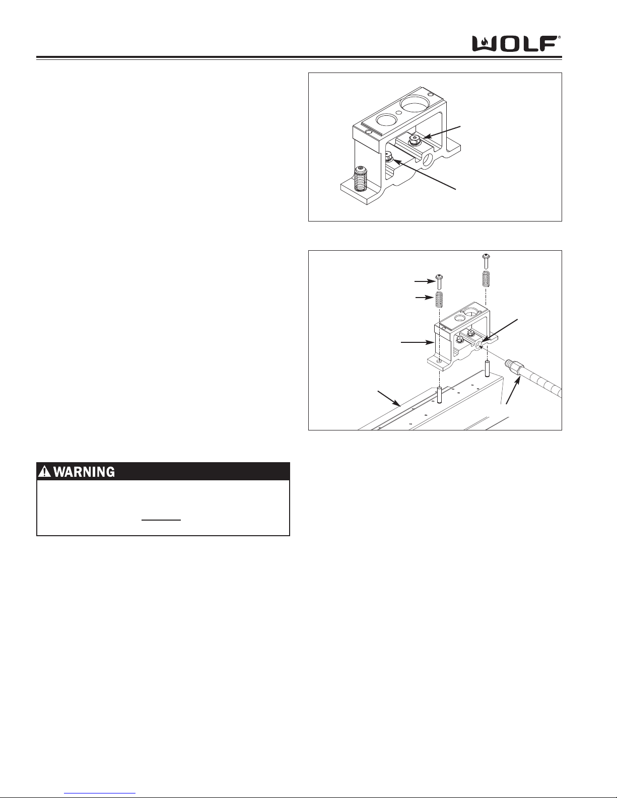
DDuuaall FFuueell RRaannggee
Component Access & Removal
4-8
Orifice Removal (SWS 17000000)
The main and simmer orifice are threaded into the orifice holder and may be extracted without removing the
orifice holder from its installation position.
To remove the orifice holder,
1. Remove burner grate and pan.
2. Use a 9/32” wrench or socket with extension, to
extract orifice from orifice holder.
(See Figure 4-12A)
Orifice Holder (SWS 17000000)
The orifice holder assembly is secured with two screws
to the unit frame. Each orifice holder assembly consists
of an orifice holder, the main and simmer orifice, hat
bracket and the mounting hardware. The orifice holder
is mounted to the hat bracket with a stand-off and
spring assembly which allows the orifice holder to flex
when the burner assembly is installed.
To remove the orifice holder,
1. Remove burner grate and pan.
2. With a 3/8” and a 7/16” open end wrenches,
remove the gas supply lines from orifice holder.
(See Figure 4-12B)
3. Extract the screws securing the orifice holder to the
hat bracket.
4. Remove springs from standoffs, then lift orifice
holder off of hat bracket.
Figure 4-12A. Orifice Location
Figure 4-12B. Orifice Holder Removal
WHEN REASSEMBLING ORIFICE TO ORIFICE
HOLDER, ONLY PIPE THREAD COMPOUND
SHOULD BE USED. DO NOT
USE TEFLON TAPE
TO SEAL GAS CONNECTIONS.
Screw
Spring
Orifice Holder
Hat Bracket
Gas
Supply Port
Main Orifice
Simmer Orifice
Gas Line
Page 49
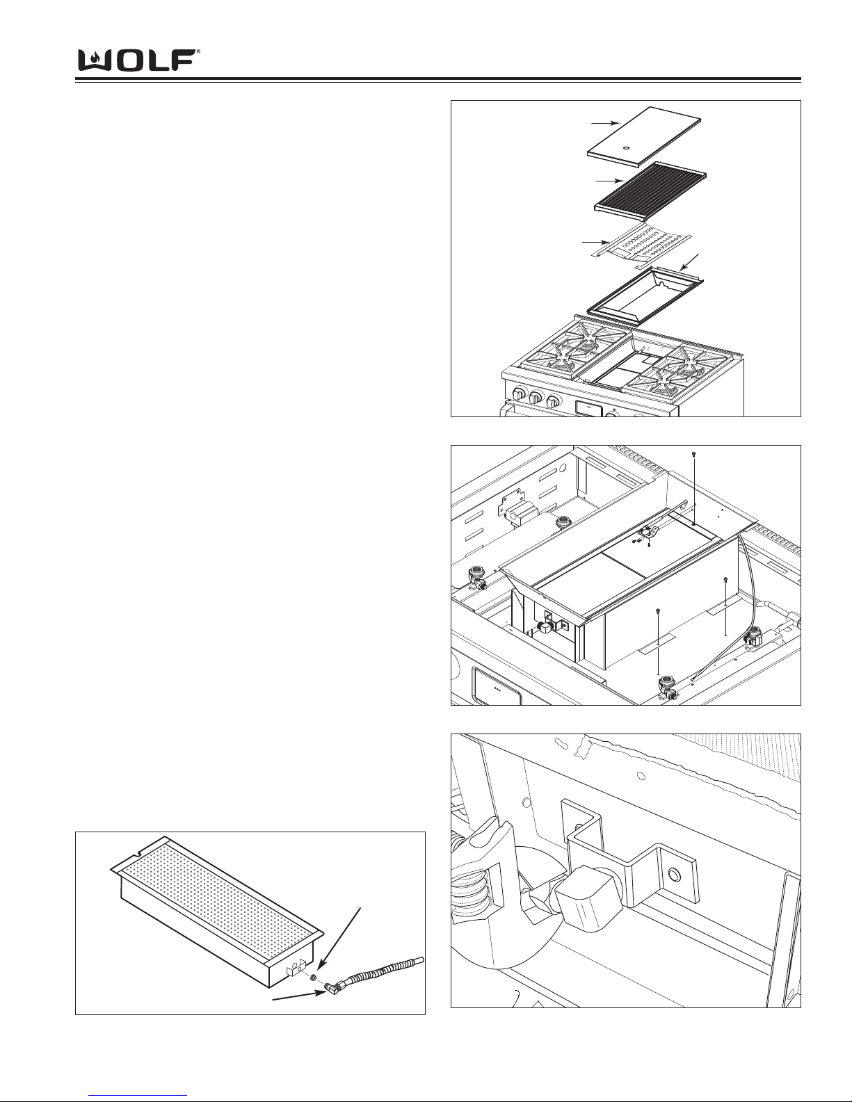
Component Access & Removal
4-9
DDuuaall FFuueell RRaannggee
Radiant
Cover
Grate
Char Pan
Figure 4-13. Components that Lift Off
Figure 4-14. Electrode and Infrared Burner Removal
Infrared Charbroiler Components
Cover, Grate, Char Pan, Radiant, Electrode, Infrared
Burner and IR Orifice
• Lift the Charbroiler cover from the unit.
• Lift the Charbroiler grate from the char pan.
• Lift the Charbroiler radiant from the char pan.
• Lift the Charbroiler frame from the top of the unit.
(See Figure 4-13)
Electrode Removal
The infrared Charbroiler electrode is attached to a
bracket with a screw and then mounted 1/8” above the
surface of the burner tile. The electrode wire is then
inserted into a wire sleeve and routed to the spark module which is located underneath the deflector shield.
In order to remove the Charbroiler electrode, disconnect
the electrode wire from the spark module. Extract the
mounting screw from the electrode bracket and pull the
electrode with wire lead up through oblong hole in the
back wall. (See Figure 4-14)
Infrared Burner Removal
After removing the components listed above, extract the
screws securing the IR weld assembly. Then, extract
the screw from the rear of the IR burner box. Lift the
burner box out by first sliding the IR weld assembly
towards the rear. Next, lift the IR weld assembly up
and rest it on the ECH shield. Disconnect the gas line
from the brass orifice elbow. Now, lift the IR burner out
of the IR weld assembly. (See Figure 4-14)
IR Orifice Removal
The orifice is located in the brass orifice elbow, which is
threaded into the orifice holder at the front of the IR
burner. The IR weld assembly must be raised up and
placed on the ECH shield for access.
To remove the orifice, first disconnect the gas line from
the brass orifice elbow. Then, unscrew the elbow from
the orifice holder and extract the orifice from the elbow
with wrenches. (See Figure 4-15 and 4-16)
Figure 4-16. IR Charbroiler Orifice Removal
IR Charbroiler Orifice
Orifice Elbow
Figure 4-15. Flexible Gas Tube Removal
Page 50
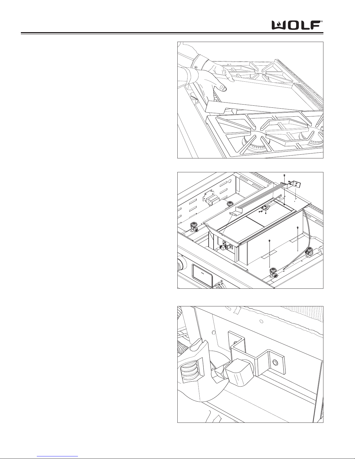
DDuuaall FFuueell RRaannggee
Component Access & Removal
4-10
Figure 4-18. Thermostat Support, Electrode and IR Weld
Assembly Removal
Figure 4-17. Griddle Plate Removal
Infrared Griddle Components
Grease Tray, Griddle Plate, Thermostat Support
Assembly, Electrode, IR Weld Assembly, Infrared
Burner, Thermostat, Solenoid and IR Orifice
Grease Tray and Griddle Plate Removal
The griddle plate is a cast iron plate that rests on top of
the griddle weld assembly. A grease tray sits in the well
of the griddle. For cleaning purposes, it tilts up from the
front edge for removal. An edge has been added to the
lip of the cooking surface, which helps in the removal of
the plate for cleaning and servicing. To remove the
griddle plate, lift the front edge of the plate from underneath the cooking surface lip. Now, place both hands
under the plate and lift it off. (See Figure 4-17)
Thermostat Support Assembly Removal
The thermostat sits in the trench of the thermostat
assembly. Pull the tip back toward the control panel
until it releases from the notch of the support assembly.
Now, lift the thermostat up and maneuver the capillary
tube out of the notch at the rear of the IR weld assembly. Then, extract the screws at the front and rear of
the thermostat support assembly and lift out. (See
Figure 4-18
Electrode Removal
First disconnect the electrode lead from the DSI board.
Now, extract the screws from the electrode bracket.
Then, pull the electrode with lead through the oblong
hole in the IR weld assembly. (See Figure 4-18)
IR Weld Assembly Removal
Extract the screws from either side of the IR weld
assembly, lift the front edge and rest it on the shield
that protects the ECH. Use a wrench to remove the
gas line from the orifice elbow. (See Figure 4-18)
Infrared Burner Removal
First remove the screw securing the infrared burner to
the IR weld assembly. Now, using an adjustable
wrench, disconnect the gas line from the orifice elbow.
(See Figure 4-19) Then, lift theIR burner out from the
IR weld assembly.
Figure 4-19. Infrared Burner Gas Line Removal
Page 51
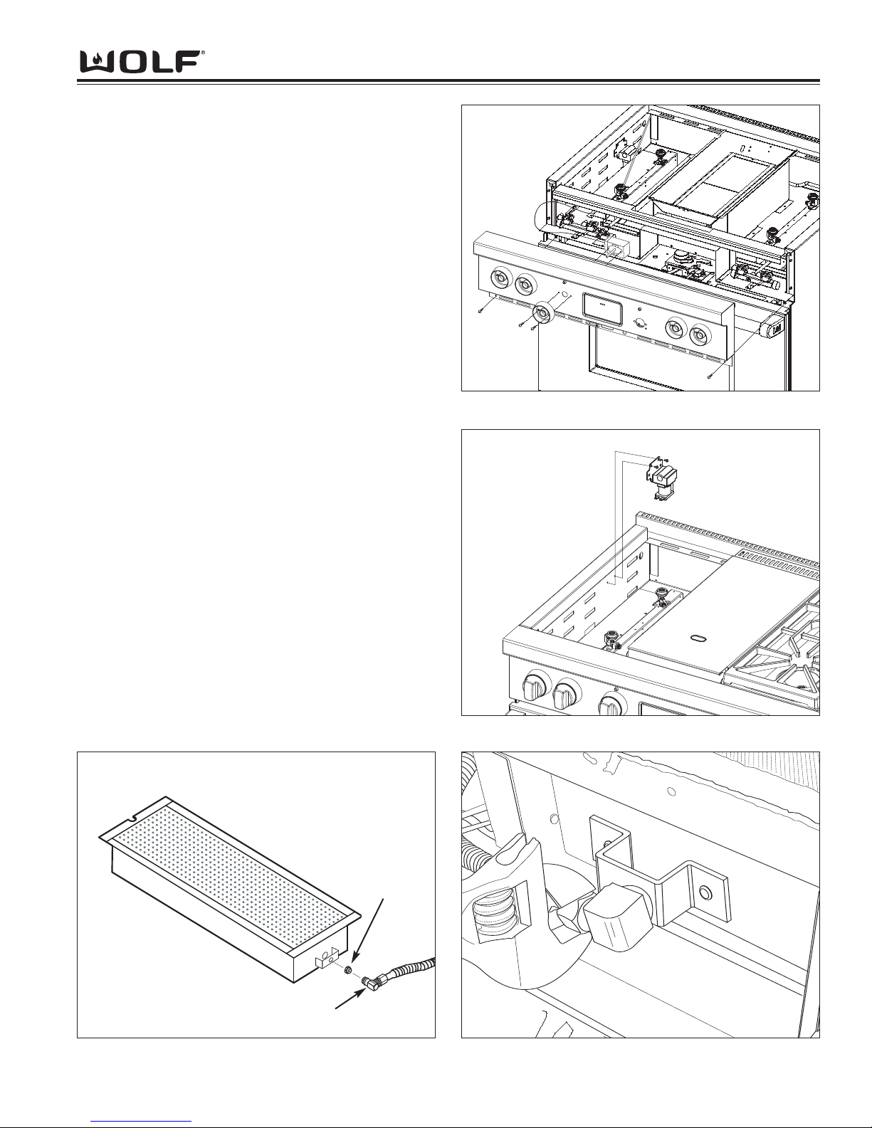
Component Access & Removal
4-11
DDuuaall FFuueell RRaannggee
Figure 4-22. Solenoid Removal
Figure 4-21. Thermostat Removal
Figure 4-23. Infrared Burner Gas Line Removal
Infrared Thermostat Removal
The griddle thermostat is mounted to the bull nose with
two screws and the thermostat bulb is inserted into a
channel on the support assembly beneath the griddle
plate.
To remove the thermostat, first lift off the griddle plate
and slide the thermostat bulb from the support assembly. Pull the griddle knob from the shaft of the thermostat and extract the thermostat mounting screws.
Remove the bull nose from the unit (See Bull Nose
Removal Instructions). Unplug the electrical leads from
the thermostat. (See Figure 4-21)
Solenoid Removal
The griddle solenoid valve is mounted to the side wall
beneath the burner pan, usually on the left hand side.
In order to remove the solenoid, the surface burner
components will need to be removed first. Extract the
solenoid cover mounting screws and remove the cover.
Disconnect the gas lines from the solenoid. Now,
extract the screws from the solenoid mounting bracket
and pull the solenoid from the unit. (See Figure 4-22)
IR Orifice Removal
The orifice is located in the brass orifice elbow, which is
threaded into the orifice holder at the front of the IR
burner. The Ir weld assembly must be raised up and
placed on the ECH shield for access.
To remove the orifice, first disconnect the gas line from
the brass orifice elbow. Then, unscrew the elbow from
the orifice holder and extract the orifice from the elbow
with wrenches. (See Figure 4-20 and 4-23)
Figure 4-20. IR Charbroiler Orifice Removal
IR Charbroiler
Orifice
Orifice Elbow
Page 52
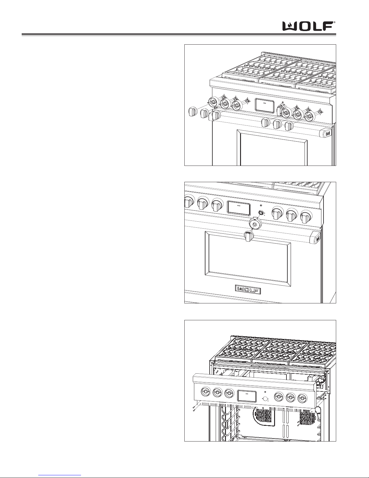
DDuuaall FFuueell RRaannggee
Component Access & Removal
4-12
Bull Nose Components
Burner Knobs, Burner Knob Bezel, Oven Selector
Knob, Function Selector Bezel, Bull Nose, Indicator
Light, Selector Switch and ECH
Burner Knob Removal
The burner knobs are marked with OFF, HI/LO and
simmer HI/LO settings. To remove burner knobs, pull
the knobs straight off the valve stem(s) of the burner
valve(s). (See Figure 4-23)
Burner Knob Bezel Removal
The burner knob bezels are attached to the bull nose
with screws. To remove the burner knob bezel(s), first
remove the burner knobs. Now using a phillips screwdriver, extract the screws that secure the bezel(s) to the
bull nose. (See Figure 4-23)
Oven Selector Knob Removal
The oven selector knob features an LCD display window built into the knob. The LCD will display the temperature of the oven cavity. It will also display abbreviated words. This allows the user to know what special
feature they are in. Such as dehydration and sabbath.
It will also display Err, this signifies that an error code
has been logged into the controller.
To remove the oven selector knob, pull the knob
straight out from the selector switch. (See Figure 4-24)
Function Selector Bezel Removal
The function selector knob is labeled with the various
cooking modes. This allows the user to turn the function selector knob to engage the various cooking
modes.
To remove the function selector knob, first remove the
oven selector knob. Now, pull the function selector
bezel straight off from the selector switch. (See Figure
4-24)
Bull Nose Removal
To remove the bull nose, first remove all the knobs and
the function selector bezel. Then, open the oven door.
Now, extract the screws from the bottom left and right
corner of the bull nose. Then, grasp the bull nose on
the sides and lift up, this will disengage the screws from
from the keyhole slots of the bull nose and remove.
(See Figure 4-25)
NOTE: To completely remove the bullnose, unplug the
ribbon cable from the ECH to control board.
Figure 4-24. Oven Selector Knob and Bezel Removal
Figure 4-23. Burner Knob Removal
Figure 4-25. Bull Nose Removal
Page 53
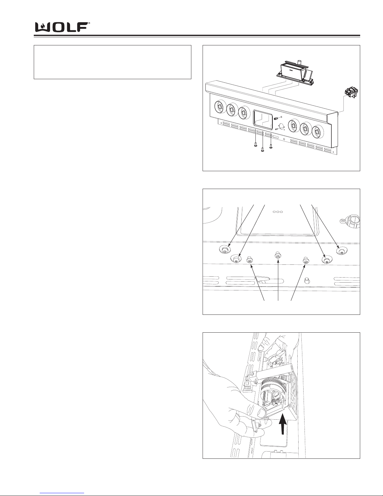
Component Access & Removal
4-13
DDuuaall FFuueell RRaannggee
Figure 4-26. Removal of Components from Bull Nose
Selector Switch Removal
To remove the selector switch, unplug the cable wire
harness from the ECH. Then, extract the screws that
secure it to the bull nose and remove. Once the selector switch has been removed, the cable wire harness
can be removed from the selector switch. (See Figure
4-26)
Indicator Light
To remove the indicator light, unplug the electrical wires
from the indicator light to the ECH. Now, remove the
spring clip that secures the indicator light to the bull
nose. Next, the indicator light can be pull out from the
front of the bull nose. (See Figure 4-26)
ECH Removal
To remove the ECH lay the bull nose down on a flat
surface with the ECH facing up towards you. Next,
locate and extract the three screws that secure the
ECH to the bull nose. (See Figure 4-27) Now, disconnect all wiring from the ECH. Then, lift the ECH straight
up and out from the bull nose. (See Figure 4-28)
ECH Adjustment
The ECH should be positioned in the center of the ECH
opening. If the ECH rubs or scraps when opening or
closing it can be adjusted with four screws located on
the underside of the bull nose.
To adjust the ECH, located the four screws under the
bull nose. Then, loosen the adjustment screws. Now,
position the ECH in the center of the opening and
retighten the adjustment screws. (See Figure 4-27)
NOTE:
To remove the selector switch, indicator light and
ECH, the bull nose will need to be removed from
the unit.
Figure 4-28. ECH Removal
Figure 4-27. Removal Screws and Adjustment Screws
ECH Adjustment Screws
ECH Removal Screws
Page 54
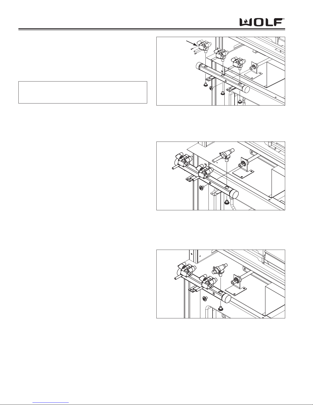
DDuuaall FFuueell RRaannggee
Component Access & Removal
4-14
Components Behind the Bull Nose
Valve Switch, Burner Valve, Charbroiler Valve,
Griddle Shut Off Valve, Manifold, Control Board,
Relay Board, Motorized Door Latch, Transformer
and Regulator
Valve Switch Removal
To remove the valve switch, first disconnect the wire
leads from the switch. Then, extract the mounting
screws and pull the switch from the valve. (See Figure
4-28)
Burner Valve, Charbroiler Valve, and Griddle Shut
Off Valve Removal
Disconnect the flexible gas lines, disconnect any wire
leads. Then, extract the screw from underneath the
manifold that secures the valve or shut off.
(See Figures 4-28, 4-29 and 4-30)
Manifold Removal
First remove all the valves and shut offs. Then, extract
the screw in the front of the manifold that secures it to
the manifold gas supply line. Now, extract the screws
that secure the manifold to the unit and lift out. (See
Figures 4-28, 4-29 and 4-30)
Figure 4-28. Burner Valve Removal
Figure 4-29. Charbroiler Valve Removal
Figure 4-30. Griddle Shut Off Removal
Valve Switch
NOTE:
To remove the following components, the bull nose
will need to be removed.
Page 55
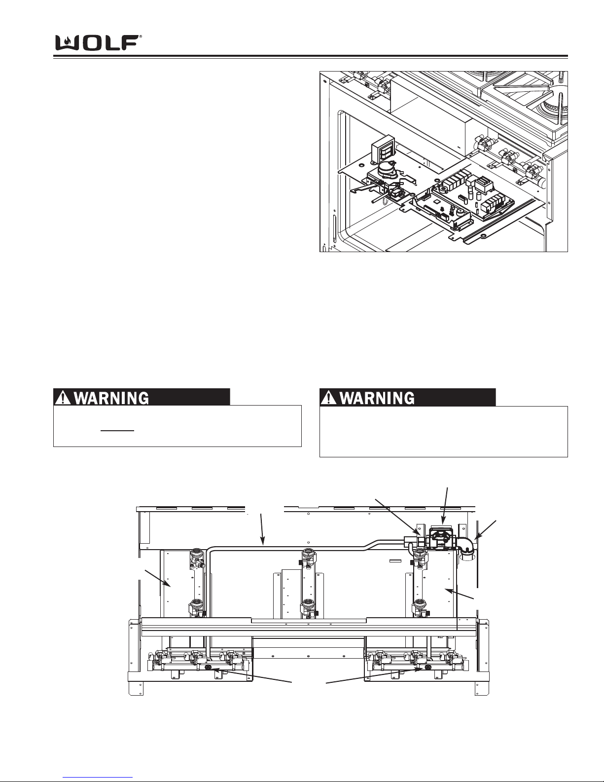
Component Access & Removal
4-15
DDuuaall FFuueell RRaannggee
Control Board, Relay Board, Motorized Door Latch and
Transformer Removal
Using a small socket and driver, extract the screws that
secures the control board plate to the unit. Then, carefully
pull the plate straight forward to the front of the unit to gain
access to the components.
NOTE: Before disconnecting any wires, make note of their
location. Make sure to reference the wiring diagram when
re-connecting any wires.
Now, extract the screw(s) which secures the component to
the control board plate and disconnect the wiring. Then,
remove the component. (See Figure 4-31)
When re-installing the control board plate with components
back into the unit, be carefully so the wiring to the components don’t get snagged and pulled off from their location.
Regulator Removal
First, pull unit out to access rear of unit. Then, shut off gas supply and disconnect electric supply. Next, remove
back panel and disconnect gas union. Now, Remove bull nose, top pan(s) depending on model configuration and
extract the screw on front of each manifold which secure the gas lines to manifolds. Next, remove the deflector
shields. Then, remove regulator cover and push gas lines out from manifolds. Now, lift entire gas line, adapter, regulator and section of black pipe disconnected at union, out from unit. Once this section has been lifted out from the
unit, disconnect the black pipe with elbow from regulator and remove the adapter from regulator. To reassemble,
just reverse these steps.
Regulator Removal
Figure 4-31. Component Removal from Control Plate
WHEN REINSTALLING VENTURI USE TORQUE
WRENCH TO TIGHTEN TO 100 INCH/LBS. OVER
TIGHTENING WILL DAMAGE UNIT AND GAS
LEAKS MAY OCCUR.
TO ENSURE PROPER BURNER OPERATION, THE
O-RINGS
MUST BE REPLACED ANY TIME THE
UNITS IS DISASSEMBLED FOR ANY REASON.
Manifold
Deflector
Shield
Deflector
Shield
Regulator
Adapter
Elbow with
Black Pipe
Screws
Page 56
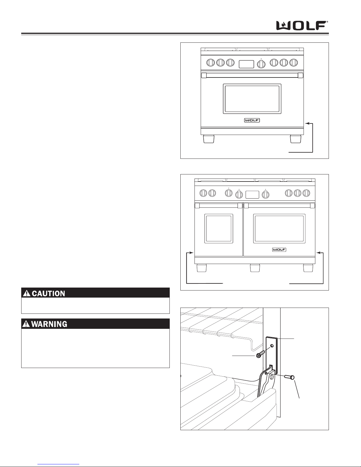
DDuuaall FFuueell RRaannggee
Component Access & Removal
4-16
Oven Door Components
Oven Door Removal
The oven door uses a spring and damper system. Only
one hinge arm is spring loaded, which requires use of
the hinge pin for removal.
On 30-inch and 36-inch units, the hinge pin will be
inserted through the hole in right hinge arm (looking at
the front of the unit). (See Figure 4-32 and 4-33)
On 48-inch and 60-inch units, the spring hinges are
located on the outside edges of the unit. On these
units, the left oven door will have the spring hinge on
the left side. The right oven door will have the spring
hinge on the right side. (See Figure 4-33)
Door(s) Removal
To remove oven door, first open the door to its fully
opened position. Insert the hinge pin through hole in
the appropriate hinge arm. (See Figure 4-34) Remove
the screw and the retainer clip from the hinge cover.
NOTE: On units with a new style single hinge retainer
plate (See Figure 4-34A), it will require the removal of
skirt prior to door removal. The new style single retainer plate will remain with the door during removal once
the two screws, securing the retainer plate, are
removed.
Close the oven door to about a 60° angle from the horizontal. Lift up on the door while continuing to pull the
door away from the unit.
For 48-inch and 60-inch units, complete this procedure
for both the left and right oven doors.
DO NOT LIFT OR CARRY THE OVEN DOOR BY THE
DOOR HANDLES.
FAILURE TO INSERT SUPPLIED PIN IN APPROPRIATE HINGE ARM WILL CAUSE DAMAGE TO UNIT,
AND POSSIBLE INJURIES MAY OCCUR.
PLACE PIN ON
SPRING SIDE OF UNIT
Figure 4-32. Pin Placement for 30” and 36” Units
PLACE PIN ON
SPRING SIDE OF UNIT
Figure 4-33. Pin Placement for 48” and 60” Units
PLATE
HINGE
PIN
SCREW
Figure 4-34. Pin Placement On Hinge
If the pin device is too long, it will rub against the
inner door liner and chip the porcelain.
Door(s) Reinstallation
To reinstall door assembly, fully extend hinge claw of
hydraulic damper hinge. Next, hold oven door on opposite sides, lift door until the hinges are aligned with the
hinge openings in the oven frame. Now, insert hinge
claw of hydraulic damper hinge into hinge pocket before
inserting the spring side hinge.
Page 57
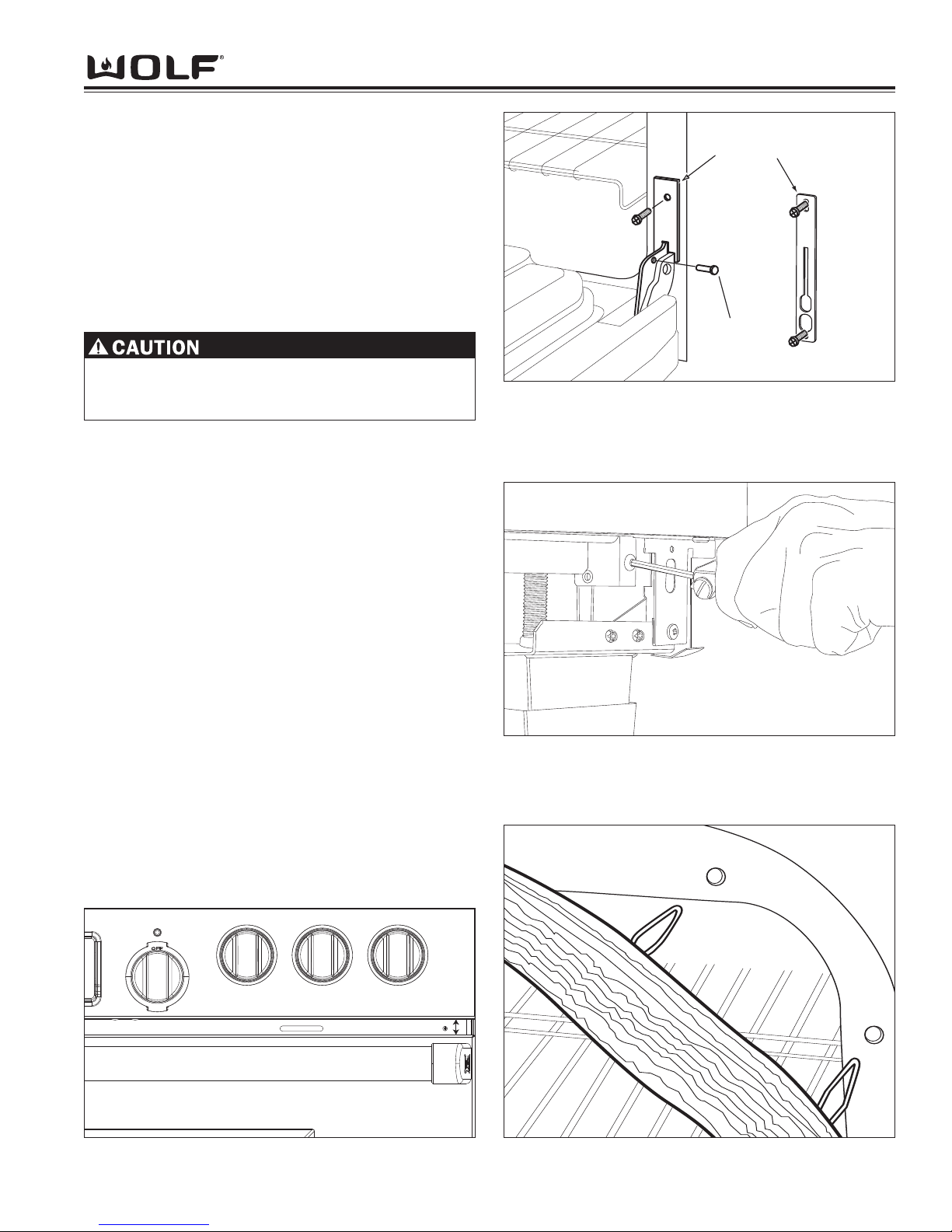
Component Access & Removal
4-17
DDuuaall FFuueell RRaannggee
Door Adjustments
To adjust doors for height use a 5/32” allen wrench to
turn the allen screw for the hinge pocket. This will raise
or lower the oven door to the desired height allowing for
proper alignment between the bull nose and the top of
the oven door. Do this procedure for each side of the
oven door until the desired alignment is obtained. (See
Figure 4-35 and 4-36)
Door Gasket Removal
First, open the oven door. Now, locate the small clips
attached to the underside of the gasket and gently pull
the clips from the mounting holes. Next, pull the ends
of the gasket out from the bottom of the door liner and
remove. (See Figure 3-37).
NOTE: On units starting with serial #16000000 the
gasket will be mounted to the front collar of the cavity.
Removal procedure is the same.
Figure 4-37. Door Gasket Mounting Figure 4-36. Alignment between Bull Nose and Door
Figure 4-35. Use a 5/32” Allen Wrench to Adjust Door
Door(s) Reinstallation (Continued)
Then, position door in hinge openings at a 30° angle
from vertical. Now, insert spring side hinge into hinge
pocket. Next, lower door to fully opened position and
remove hinge pin. Reinstall plate and screw over hinge
opening. Then, open and close door to insure its properly installed.
NOTE: On units with a new style single hinge retainer
plate (See Figure 4-34A), you will need to install the
single hinge retainer onto the hinge claw prior to
installing door.
NOTE: If replacing old style hinge retainer with new
style (See Figure 4-34A), you will be required to drill a
9/64” hole for the lower screw once door is installed and
prior to installing skirt.
For 48-inch and 60-inch units, complete this procedure
for both the left and right oven doors.
Hinge
Retainer
Plate
Hinge
Pin
Old Style
New Style
Figure 4-34A. Old style and New Style Hinge Retainer
Failure to screw in the bottom screw will lead to
future failure. The hole must be drilled and used to
secure the bracket.
Page 58
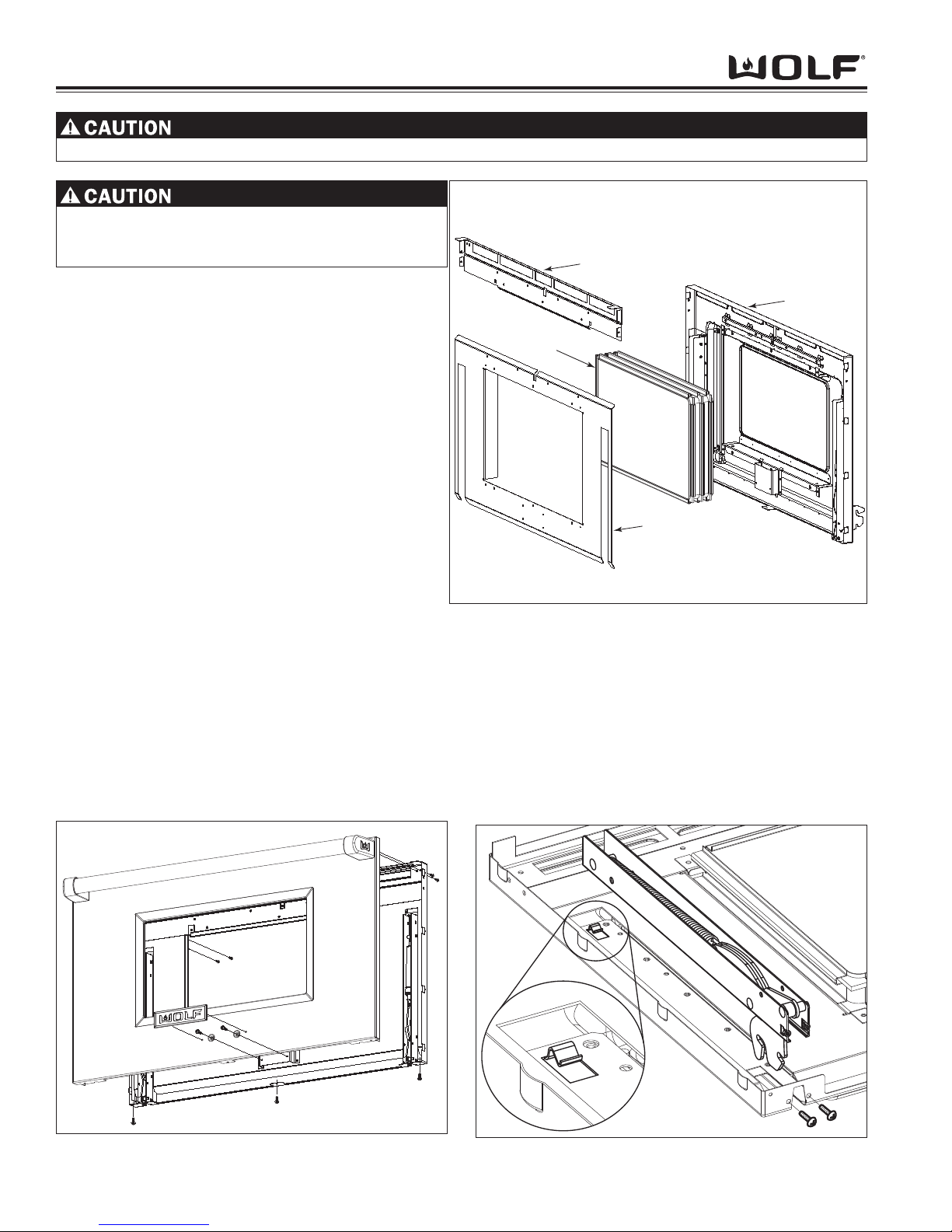
DDuuaall FFuueell RRaannggee
Component Access & Removal
4-18
When removing or disconnecting the door hinge, remember it could recoil quickly when released.
Figure 4-40. Spring and Hydraulic Hinge Removal
Figure 4-39. Glass Pack Assembly Removal
Door Liner Bracket
Glass Pack
Assembly
Door Liner
Door Baffle
Outer Door Skin Assembly Removal
First, remove the oven door assembly and lay on front.
Extract the two screws on the inside top of the door
liner. Next, extract the three screws at the bottom of
the outer door skin. Then, remove the outer door skin
with handle and lay on front. Now, extract the four
screws from the door handle assembly and remove.
Remove the heat shield and insulation from the outer
door skin. (See Figure 4-38).
Glass Pack Removal
To begin, remove the oven door assembly. Then
remove the outer door skin. Now, extract the screws
that secure the door liner bracket to the door liner, also
extract the screws on the sides of the door liner bracket
in order to remove. Now, remove door baffle from
around glass pack. Now, lift the glass pack up and
remove. (See Figure 4-39)
Hinge Removal
To begin, remove the oven door assembly and outer
door skin assembly. Next, extract the two screws at the
bottom corner of the door liner. Raise the bottom of the
door hinge assembly from the door liner. Then, using a
small flat bladed screwdriver, carefully raise the tab at
the top of the hinge and slide the hinge out from under
tab and remove. (See Figure 4-40)
Figure 4-38. Door Skin Removal
Hydraulic Hinge Removal
To begin, remove the oven door assembly and outer
door skin assembly. Next, extract the two screws at the
bottom corner of the door liner. Now, raise the bottom
of the hydraulic hinge assembly from the door liner.
Then, using a small flat bladed screwdriver carefully
raise the tab at the top of the hydraulic hinge and slide
the hinge out from under tab and remove. (See Figure
4-40)
Logo must be removed prior to disassembly of
door. Use of a heat gun and putty knife, wrapped
with tape, will help in the removal.
Page 59
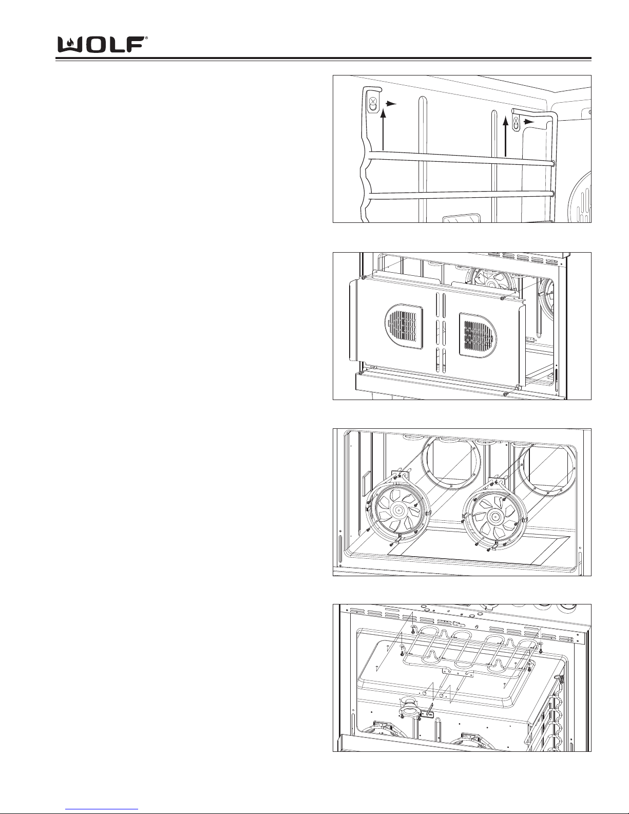
Component Access & Removal
4-19
DDuuaall FFuueell RRaannggee
Figure 4-42. Convection Baffle Removal
Oven Compartment Components
Left and Right Rack Guide Removal
First, remove oven racks. Then, extract the screws in
each corner, top and bottom of the rack guide and lift
guide out.
NOTE: On units starting with serial #16000000 the
oven rack guides remove without extracting any screws.
Simply lift upwards on the rack to disengage the shoulder screw from the keyhole slot on the rack guide and
remove. (See Figure 4-41)
Oven Light Removal
To remove the oven light you will need to remove the
oven racks and guides. Next, the light cover will need
to be removed by gently pulling the light cover off the
light housing. Now, to remove the light bulb, lift the
bulb straight up and out of the light bulb socket.
NOTE: When replacing the light bulb with a new one,
wrap a clean cloth around the new bulb so fingerprints
are not left on the new bulb. The greasy residue from
fingerprints may cause the new bulb to burn out prematurely.
Convection Baffle Plate Removal
First, the racks and rack guides will need to be
removed. Now, extract the screws in each corner, the
top and bottom of the convection baffle plate and
remove. (See Figure 4-42)
Convection Fan Assembly Removal
The racks, rack guides and convection baffle plate will
need to be removed first. Then, extract the screws
around the convection fan and the top screw located
between the element (where the element goes through
the oven cavity). (See Figure 4-43) Now, pull fan
assembly into oven cavity and disconnect wiring and
remove.
Broil Element and Broil Pan Removal
To have more room when removing the broil element,
remove the racks from the unit. Next, extract the four
screws that secure the element and broil pan to the
ceiling of the oven cavity. Now, extract the two screws
that secure the element leads through the oven cavity.
Then, pull the element forward and down into the oven
cavity until the terminals and wires are exposed. Now,
disconnect the wires and remove the element and broil
pan. (See Figure 4-44)
Smoke Catalyst Removal
The catalyst is located in the rear ceiling of the oven
cavity. To remove, extract the two screws and pull catalyst straight down and remove. (See Figure 4-44)
Figure 4-44. Broil Element and Smoke Catalyst Removal
Figure 4-43. Convection Fan Removal
Figure 4-41. Removable Rack Guides
Page 60
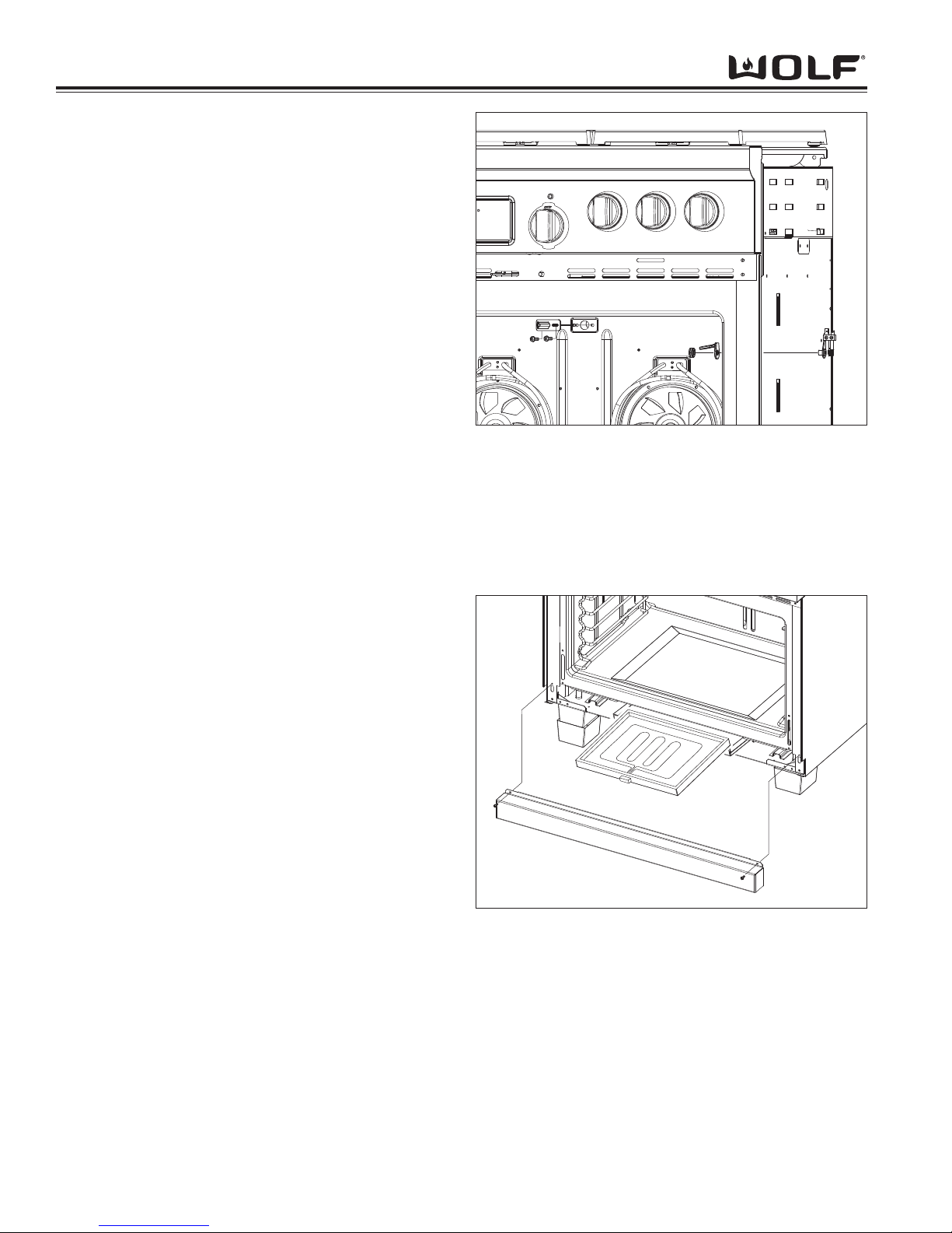
DDuuaall FFuueell RRaannggee
Component Access & Removal
4-20
Figure 4-45. RTD and Probe Removal
Figure 4-46. Bake Element Removal
Temperature Sensor Removal
Extract the two screws which secure the sensor to the
oven cavity. Next, carefully pull the sensor with wire
leads straight out from the oven cavity, until the molex
connector is inside the oven cavity. Now, unplug the
molex connector and remove the temperature sensor.
(See Figure 4-45)
NOTE: When the moles connector is disconnected,
make sure the male end of the connector doesn’t fall
back into the hole. If it does, the unit may have to be
pulled out from its installation in order to reconnect the
molex connectors for the sensor.
Probe Cover and Probe Switch Removal
To remove the probe cover, first you will need to raise
the probe cover up. Now, using a wrench, loosen and
remove the nut. Now, the cover can be removed.
To remove the probe switch the outer side panel on the
right side of the unit will need to be removed. Next,
extract the screw and remove the access panel for the
probe switch. Now, pull the switch from the oven cavity
and disconnect the wires from the switch terminals.
(See Figure 4-45)
Hidden Bake Element Removal
The hidden bake element is located in the front of the
unit behind the grill skirt.
To remove the bake element, first remove the grill skirt.
Now, disconnect the wiring harness for the bake element. Then, extract the screws that secure the heat
shield. Next, carefully pull the pan assembly straight
forward and tilt down. Now, slide the element pan
assembly towards the front until it stops. Then, lift the
element assembly out from the pan assembly.
(See Figure 4-46)
NOTE: When re-installing the bake element and pan
assembly back into the unit, be careful not to break off
the white insulation that lines the element.
Page 61
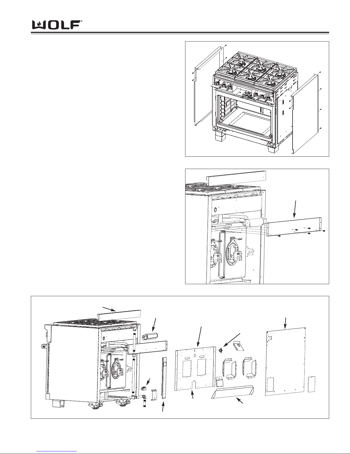
Component Access & Removal
4-21
DDuuaall FFuueell RRaannggee
Figure 4-49. Removal of Back Panel Components
Side and Back Panel Components
Outer Side Panel Removal
In order to remove the side panel, the unit must be
pulled from its installation and remove the door assembly, bull nose assembly, grill skirt and island trim or riser
first. Now, extract the four screws from the rear of the
side panel and the two screws from the front of the side
panel. Then, grasp the bottom of the side panel and tilt
outward slightly while lifting the side panel upward and
remove. (See Figure 4-47)
Cooling Fan Removal
The cooling fan is located at the rear of the unit
between the top surface burners and the oven. To
remove the cooling fan, first extract the screws that
secure the side panels and island trim or riser. Now,
extract all the screws that secure the back panel. Then,
extract the two screws in the lower middle of the fan
mounting bracket (these two screws secure the cooling
fan in position). Next, remove the fan mounting bracket. Then, disconnect the wiring and remove the cooling fan. (See Figure 4-48)
Thermo Limiter
The thermo limiter can be reset if it trips. The thermo
limiter is mounted on the back panel insulation (this is a
metal panel). To remove the thermo limit, the back
panel will need to be removed. Then, disconnect the
wiring to the limit and remove.
NOTE: If the thermo limiter has been tripped, you can
reset it by removing the convection baffle and left convection fan from the oven cavity. Reach through the left
convection fan opening. The limiter is located directly
above the opening and to the right. You can now reset
the limit for the oven.
Figure 4-47. Outer Side Panel Removal
Figure 4-48. Cooling Fan Removal
Fan Mounting
Bracket
Island Trim
Cooling
Fan
Cooling Fan
Mounting Bracket
Back Panel
Terminal
Block
Thermal Limit
Cooling Air Dam
Oven Vent
Back Panel
Insulation
Page 62

4-22
Component Access & Removal
DDuuaall FFuueell RRaannggee
Page 63

Troubleshooting Guide
5-1
DDuuaall FFuueell RRaannggee
SECTION 5
TROUBLESHOOTING GUIDE
Page 64

DDuuaall FFuueell RRaannggee
Troubleshooting Guide
5-2
TROUBLESHOOTING GUIDE
This section of the manual contains the General Troubleshooting Guide which will help the Service Technician troubleshoot a Wolf Dual Fuel Range.
How to Use the Troubleshooting Guide
The troubleshooting guide table of contents shows how the troubleshooting guide is laid out. The troubleshooting
guide is organized into component areas with the most common problems listed first.
On the table of contents identify the description of the problem that the unit is experiencing. To the left of the problem description is a letter. Locate that letter in the left column of the Troubleshooting Guide. The center column of
the troubleshooting guide will identify the possible causes for the problem. The information to the right of the possible causes will explain what tests to perform in order to determine if what you are checking is the cause, and/or what
action to take to correct the problem.
Diagnostic Mode
To initiate Diagnostic Mode, the oven control knob bezel must be OFF position. Now, press and hold CLOCK key
and TIMER key for 3 seconds. The ambient cavity temperature will be displayed in the temperature readout knob.
Now, turn the oven temperature readout knob to the right seven separate times, this will toggle from error code 1
thru 7. To return to error code number one, turn the oven temperature readout knob to the left seven separate
times. The software version will be displayed in the hours and minutes display of the clock. To clear error codes
once unit has been fixed, press the CLEAR key. To exit Diagnostic Mode, press the ENTER key.
NOTE: Once diagnostic mode is entered, there is a 2 minute time out, which is restarted each time a key is
pressed.
Error Indicators
Error codes can give a visual and audible alarm. The visual indication will be “Err” displayed in the Cook Time digits
and the number or letter of the error code will be displayed in the Stop Time digits of the Electronic Control Housing.
The Oven Temperature Readout Knob will also show “Err” in the display window. The last seven errors will be
stored in the EEPROM for recall when in diagnostic mode.
FIELD OPTION MODE
Field option mode allows for the user to adjust or change specific options of the ECH and oven controller, such as
User Preference Offset, 12 hour to 24 hour clock and ° Fahrenheit to °Celsius temperature.
UPO (User Preference Offset)
This option allows the user to offset a specific oven temperature ±35° in 1°F (Fahrenheit) increments or ± 19° in 1°C
(Celsius) increments.
To initiate, press and hold the CLOCK key for 5 seconds. The current UPO will be displayed in the temperature
readout knob, turning the knob at this point you can change the UPO. Turn the knob to the left or right to increase
or decrease the UPO in 1° increments as much as ±35°.
Changing Clock to 24 Hours
To set 24 hour clock, press and hold CLOCK key on display panel for 5 seconds. Now, press CLOCK key to change
from 24 hour to 12 hour or vice versa. Then, press ENTER or after short delay the clock will set by default.
Fahrenheit to Celsius
The oven temperature can be changed to read Fahrenheit or Celsius temperature..
To initiate, press and hold CLOCK key on display panel for 5 seconds. Now, press COOKTIME key to change from
°F and °C or visa-versa. Next, press ENTER key on the display panel or after short delay °F or °C will set by
default.
Page 65

Troubleshooting Guide
5-3
DDuuaall FFuueell RRaannggee
page #
Problems Associated with the Surface Burners
A. Constant Sparking.........................................................5-4
B. Intermittent Spark.........................................................5-4
C. Poor Ignition .................................................................5-4
D. No Ignition.....................................................................5-4
E. Popping Noise.............................................................. 5-4
F. Flame Appearance....................................................... 5-4
1. Tall flame
2. Yellow flame
3. Pulsing flames
Problems
Associated with the Charbroiler
G. Constant Sparking.........................................................5-5
H. Intermittent Spark..........................................................5-5
I. Poor Ignition..................................................................5-5
J. No Ignition.....................................................................5-5
K. Uneven Heat.................................................................5-5
L. Too Hot..........................................................................5-5
Problems
Associated with the Griddle or FT
M. Constant Sparking.........................................................5-6
N. Intermittent Spark..........................................................5-6
O. Poor Ignition .................................................................5-6
P. No Ignition.....................................................................5-6
Q. Cannot Regulate Temperatures....................................5-6
R. “CFH Indicator Light ON but NO Heat on Griddle
Surface..........................................................................5-7
S. “CFH Indicator light OFF and NO Heat on Griddle
Surface..........................................................................5-7
Problems
Associated with the Function Selector
Bezel and Oven Selector Knob
T. Oven Will Not go into Cooking Mode............................5-7
U. Oven W
ill
Enter Cooking Mode but No Display in
Oven Selector Knob......................................................5-7
V. Oven Selector Knob Continuously Increase
and Decreases Temperature Reading..........................5-7
W. “PF” Displayed in Oven Selector Knob.........................5-7
X. “Hot” Displayed in Oven Selector Knob........................5-7
Y. “Err” Displayed in Oven Selector Knob.........................5-7
Z. “Sab” Displayed in Oven Selector Knob.......................5-7
Troubleshooting Guide Table of Contents
page #
Problems
Associated with the Electronic
Control Housing - (ECH)
AA. No Display in ECH........................................................5-8
BB. Unresponsive Key Pad(s).............................................5-8
CC. ECH Doesn’t Flip Out................................................... 5-8
DD. Unit Beeps when any area of the ECH is touched.......5-8
Problems
Associated with the Oven
EE. Long Preheat................................................................ 5-9
FF. No Heat.........................................................................5-9
GG. No Broil.........................................................................5-9
HH. “CFH” Indicator Light Does Not Light when turned
to Cooking Mode...........................................................5-9
II. Oven Temperature Too High or Too Low......................5-9
JJ. Temperature Probe Not Working.................................. 5-9
KK. Cooling Fan Does Not Work.........................................5-9
LL. Cooling Fan Noisy.........................................................5-9
MM.Convection Fan Does Not Work.................................5-10
NN.Noisy Convection Fan................................................ 5-10
OO.Convection Fan Does Not Shut Off
When Door Open........................................................5-10
PP. Oven Light Does Not Work.........................................5-10
QQ.Door will Not Lock in Self-Clean Mode.......................5-10
Problems
Associated with Error Codes
Error Codes.......................................................................5-10
ECH Troubleshooting Flow Chart.................................. 5-11
DSI Board Troubleshooting Flow Chart........................5-12
T
esting the Oven Relay Boards
Element Testing.......................................................... 5-13
RTD Testing.......................................................................5-13
Probe Testing.....................................................................5-13
Fans and Motors................................................................5-14
Ohm Testing Elements at Relay Board..........................5-14
Page 66
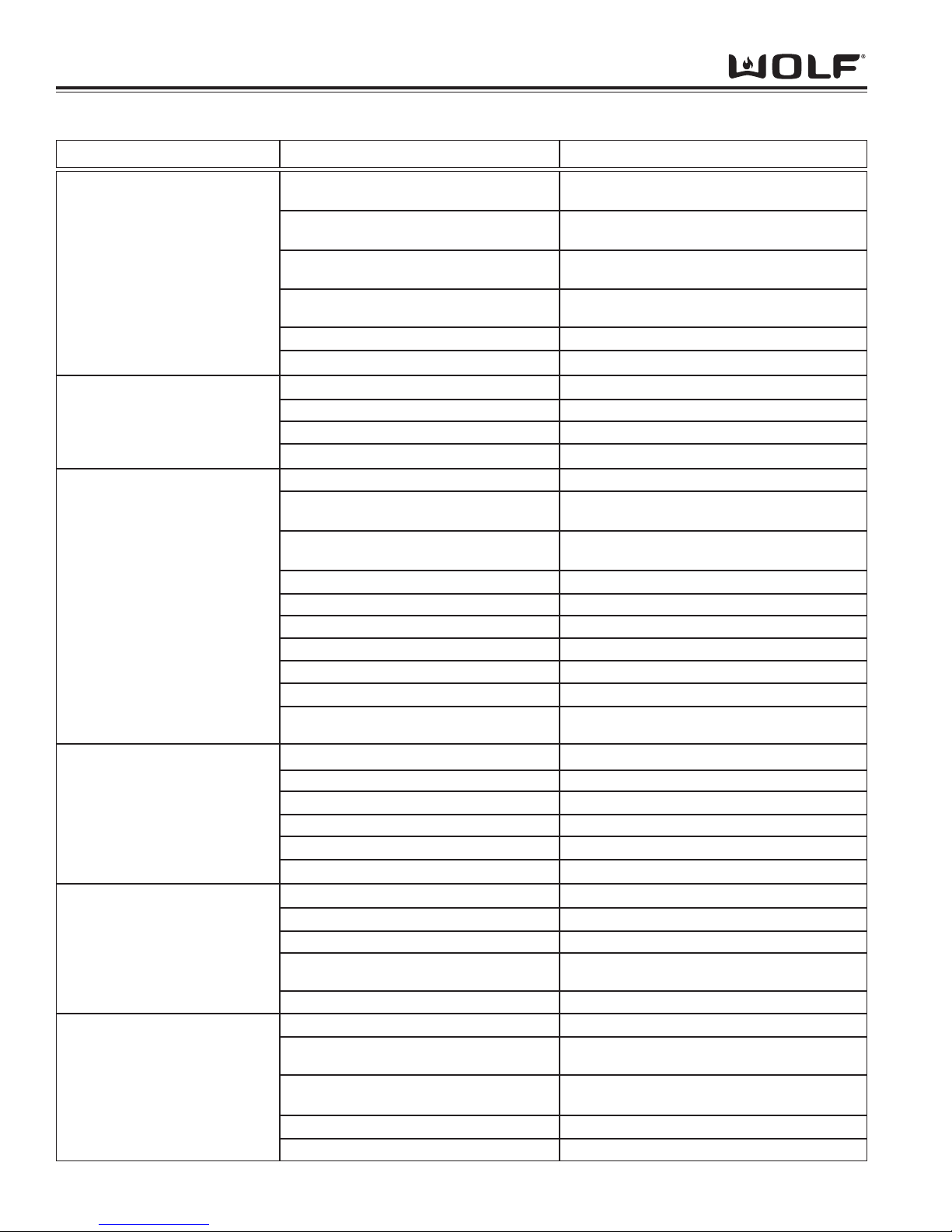
DDuuaall FFuueell RRaannggee
Troubleshooting Guide
5-4
PROBLEM POSSIBLE CAUSE TEST / ACTION
A. CONSTANT SPARKING AT
SURFACE BURNER
B. INTERMITTENT SPARKING
AT SURFACE BURNER
C. POOR IGNITION AT
SURFACE BURNER
D. NO IGNITION AT SURFACE
BURNER
E. POPPING NOISE AT
SURFACE BURNER DURING
SIMMER MODE
F. FLAME APPEARANCE ON
SURFACE BURNER(S)
1. Tall flame
2. Yellow flame
3. Pulsing flames
Ground wire disconnected at outlet or
inside unit
Spark module wired incorrectly or
defective
Electrode not positioned properly
Burner head not properly positioned on
inner distribution ring
Defective micro switch at burner valve
Cut or splice in electrode wire
Dirty electrode
Cracked or damaged electrode
Cut or splice in electrode wire
Loose wire connection at spark module
Defective spark module
Burner head not properly seated on inner
distribution ring
Electrode not positioned properly
Partially plugged ports in burner head
O-rings not properly installed
Debris on inner distribution ring
Inner distribution ring has burr or crack
Improper Gas orifice
Gas pressure
Improper gas type
Defective micro-switch at burner valve
Defective/dirty electrode
Defective or loose wiring
Defective spark module
No Power
No gas to unit
Burner head not seated properly
O-rings damaged or not seated properly
Burr on bottom of burner head
Burner head damaged or dirty with food
debris
Inner distribution ring cracked or warped
Burner head not positioned properly
Burners not getting enough primary or secondary air
Port holes in burner head not to specification or damaged/dirty
Incorrect gas orifices
Gas pressure
May have to call an electrician. Check internal
connections, may have to wire correctly
Rewire spark module(s) or replace
Reposition electrode. Electrode should be seated down to cooktop pan.
Rotate to correct position and advise owner
Replace micro switch
Replace electrode wire
Clean with wire brush
Replace electrode
Replace electrode wire
Repair wire connection
Replace spark module
Rotate to correct position and advise owner
Reposition electrode. Electrode should be seated down to cooktop pan.
Clear/clean as necessary
Install properly or replace if defective
Clean/remove debris
Replace inner distribution ring
Check orifice stamp number
Check gas pressure with a manometer
Check for gas type and advise owner if improper. May have to convert unit to LP/Natural gas
Replace micro switch
Replace/clean electrode
Replace/repair wiring
Replace spark module(s)
Check outlet and circuit breaker
Check gas pressure with a manometer
Reposition burner head and advise owner
Replace/reposition o-ring
Replace burner head
Replace/clean burner head
Replace inner distribution ring
Make sure burner head is locked in properly
Make sure air vents at front of burner box are
not blocked
Replace/clean burner head
Check stamp number on orifices
Check gas pressure using a manometer
Problems Associated with the Surface Burners
Page 67
Troubleshooting Guide
5-5
DDuuaall FFuueell RRaannggee
PROBLEM POSSIBLE CAUSE TEST / ACTION
G. CONSTANT SPARKING AT
CHARBROILER
H. INTERMITTENT SPARKING
AT CHARBROILER
I. POOR IGNITION AT
CHARBROILER
J. NO IGNITION AT
CHARBROILER
K. UNEVEN HEAT AT
CHARBROILER
L. CHARBROILER TOO HOT
Defective micro switch at burner valve
Defective Spark Module
Arcing at spark module to bracket or unit
chassis
Dirty electrode
Cracked or damaged electrode
Defective micro switch at burner valve
Arc at cut or splice in electrode wire
Defective Spark Module
Cracked or damaged electrode
Electrode not positioned properly to
Infrared burner, not close enough to tile surface.
Partially plugged holes in the burner tile
Wrong orifice size
Blockages in mixing tube or orifice
Gas pressure
Bent orifice bracket holder
Improper gas type
Defective micro switch
Loose or bad wire connection
Defective sparker
Defective Spark Module
No power
No gas
Short to spark module bracket or chassis
Unit not level
Radiant plate not in correct position or
installed
Incorrect orifice
Replace micro switch
Replace Spark Module
Check for break in insulation or missing
Clean food debris from electrode
Replace electrode
Replace micro switch
Replace electrode
Replace Spark Module
Replace electrode
Reposition electrode properly to Infrared burner.
Electrode should be clear of the screen and 1/8”
above the tile
Clear as necessary with wire paper clip.
Replace burner if too may burner holes are
clogged.
Check orifice stamp number. Replace if incorrect
Clear or clean as necessary
Check gas pressure using a manometer
Straighten so that gas jet is aimed straight down
mixing tube or replace bracket holder
Check for gas type and advise owner if improp-
er. May have to convert unit to LP/Natural gas
Replace micro switch
Check all wires per wiring diagram
Replace sparker
Replace Spark Module
Check outlet and circuit breaker
Check gas pressure using manometer
Visually inspect the spark module bracket
Level unit from front to rear and side to side
Correct position of Radiant Plate or install if
missing
Verify proper orifice is installed for gas type
Problems Associated with the Charbroiler
Page 68
DDuuaall FFuueell RRaannggee
Troubleshooting Guide
5-6
M. CONSTANT SPARKING AT
GRIDDLE / FT
N. INTERMITTENT SPARKING
AT GRIDDLE / FT
O. POOR IGNITION AT
GRIDDLE
P. NO IGNITION AT
GRIDDLE / FT
Q. CANNOT REGULATE
TEMPERATURE AT
GRIDDLE
Ground wire disconnected at outlet in wall
or power cord to unit terminal block
Ground wire on DSI board loose or defec-
tive
Defective solenoid assembly
Arc at cut or splice in electrode wire
Cracked or damaged electrode
Arc at cut or splice in electrode wire
Bad connection at the J1 connector on the
DSI board
Bad connection at the GND connector on
the DSI board to unit chassis
Defective DSI board
Cracked or damaged electrode
Electrode not positioned properly to
Infrared burner, not close enough to tile surface
Partially plugged holes in the burner tile
Incorrect orifice size
Gas pressure
Blockages in mixer tube or orifice
Bent orifice bracket holder
Improper gas type
Defective electrode
No gas
Defective DSI board
Kinked or pinched capillary tube on the
thermostat
Thermostat bulb not installed properly
Defective thermostat
May have to call an electrician
Check ground wire. Replace if defective
Replace solenoid assembly
Replace electrode
Replace electrode
Check for break in insulation. Replace elec-
trode if defective
Perform DSI board troubleshooting procedures
located at end of section 6
Check GND wire connections. Ohm ground
wire. Replace if defective
Perform DSI board troubleshooting procedure
located at end of section 6
Replace electrode
Reposition electrode properly to Infrared burner.
Electrode should be clear of the screen and 1/8”
above the tile
Clear as necessary with wire paper clip.
Replace burner if too many burner holes are
clogged.
Check orifice stamp number. Replace if incorrect
Check gas pressure with a manometer
Clear or clean as necessary
Straighten bracket holder so gas jet is aimed
straight down mixing tube or replace bracket
holder
Check for gas type and advise owner if improp-
er. May have to convert unit to LP/Natural gas
Ohm electrode with wire. If open replace electrode
Check gas supply, make sure gas is turned on
at shut off valve on manifold and supply source.
Check gas pressure with a manometer
Perform DSI board troubleshooting procedures
located at end of section 6
Straighten capillary tube if possible. Replace
thermostat.
Install thermostat bulb properly
Replace thermostat
PROBLEM POSSIBLE CAUSE TEST / ACTION
Problems Associated with the Griddle
Page 69
Troubleshooting Guide
5-7
DDuuaall FFuueell RRaannggee
PROBLEM POSSIBLE CAUSE TEST / ACTION
R. “CFH” INDICATOR LIGHT
ON
BUT NO HEAT ON
GRIDDLE SURFACE
S. “CFH” INDICATOR LIGHT
OFF
AND NO HEAT ON
GRIDDLE SURFACE
Improper Seal at bull nose to burner box
Thermostat bulb incorrectly positioned on
thermostat support assembly
Defective solenoid
Electrode not positioned properly to
Infrared burner, improper gap to tile surface
Shut off valve on manifold in off position or
supply gas not turned on
Defective thermostat
No power to unit
Check griddle operation with cooling fan OFF does griddle work? If yes, check with cooling
fan ON. If no, check for gaps and proper sealing of burner box
Reposition thermostat bulb
Ohm solenoid. Replace if defective
Reposition electrode properly to Infrared burner.
Electrode should be clear of the screen and 1/8”
above the tile
Check gas supply, make sure gas is turned on
at shut off valve on manifold and supply source.
Check gas pressure with a manometer
Ohm thermostat. Replace if defective
Reset breaker / turn on electrical power to unit
Problems Associated with the Griddle
Problems Associated with the Function Selector Bezel and Oven Selector Knob
PROBLEM POSSIBLE CAUSE TEST / ACTION
T. OVEN WILL NOT GO INTO
COOKING MODE
U. OVEN WILL
ENTER COOKING MODE BUT NO DISPLAY IN OVEN SELECTOR
KNOB
V. OVEN SELECTOR KNOB
CONTINUOUSLY INCREASE
OR DECREASES TEMPERATURE READING
W. “PF” DISPLAYED IN OVEN
SELECTOR KNOB
X. “Hot” DISPLAYED IN
OVEN SELECTOR KNOB
Defective wires from ECH to selector
switch
Defective Oven Selector Knob
Defective selector switch
Loose or defective wire harness or connection from selector switch to ECH
Defective selector switch
Defective ECH
Oven selector knob stuck
Unit had a power failure
Oven temperature to hot for cooking mode
selected
Loose or defective connection at J2 connector on oven controller
RTD out of specifications
If “Hot” is displayed, a mode was attempted
while the temperature was above the
threshold.
Check connectors by unplugging each end.
Then, plug connectors back in and check mode.
Still not working, ohm wires on cable from ECH
to selector switch. Replace if defective
Ohm knob. Replace if defective
Replace selector switch
Reseat connections. Check continuity of wire
harness, replace if defective.
Replace selector switch
Replace ECH
Turn knob to HI or LO position and let go.
Does temperature readout stop increasing or
decreasing? If yes, can the problem be recreated? If yes, replace selector switch. If no, problem fixed - knob was stuck
Turn oven selector bezel to cooking mode, then
back to OFF to reset
Open oven door to cool oven cavity temperature
Check connections at J2. Unplug and reseat
Ohm RTD sensor. Replace if out of specification according to technical data
A single long beep will occur. Allow the oven to
cool down, then select mode and temperature
desired.
Page 70
DDuuaall FFuueell RRaannggee
Troubleshooting Guide
5-8
PROBLEM POSSIBLE CAUSE TEST / ACTION
AA . NO DISPLAY IN ECH
BB. UNRESPONSIVE KEY
PAD(S)
CC. ECH DOESN’T FLIP
OUT
DD. UNIT BEEPS WHEN
ANY AREA OF THE ECH
IS TOUCHED
Temperature knob not inserted properly
into selector switch
ECH needs to reboot
Circuit breaker tripped, no power
Loose or defective wire connection(s)
Defective Relay Board
Defective Oven Controller
Unit in Sabbath feature
ECH needs to reboot
Loose/defective cable connection from
oven controller to electronic control housing
Defective key pad(s)
Defective ECH
ECH rubbing on control panel
Defective ECH
Defective ground between ECH and unit
Spring on ECH binding on mounting bracket and housing
Broken spring on ECH mounting bracket
Pull temperature knob out and reinsert fully
Turn circuit breaker off for 5 seconds, then turn
back on
Reset circuit breaker. May have to call an electrician
Perform testing procedure located at end of
section 6
Perform testing procedure located at end of
section 6
Perform testing procedure located at end of
section 6
Turn oven bezel to OFF to exit
Turn circuit breaker off for 5 seconds, then turn
back on
Unplug cable connections and ohm cables, if
defective, replace cable. If good, reinsert cable
Replace ECH
Replace ECH
Recenter ECH with adjustment screws located
on underside of control panel
Replace ECH
Check continuity using ohm meter. Place leads
on ECH assembly and the unit. Push the ECH
open and closed while performing continuity
checks. No reading, go to next possible cause
Re-center spring in-between bushings
Replace ECH
Problems Associated with the Electronic Control Housing (ECH)
Y. “Err” DISPLAYED IN
OVEN SELECTOR KNOB
Z. “SAb” DISPLAYED IN
OVEN SELECTOR KNOB
Error code has been logged into oven controller
Unit in sabbath feature
Initiate diagnostic mode to displayed error code.
Repair procedure according to error code displayed
Turn oven bezel to OFF to exit
Page 71
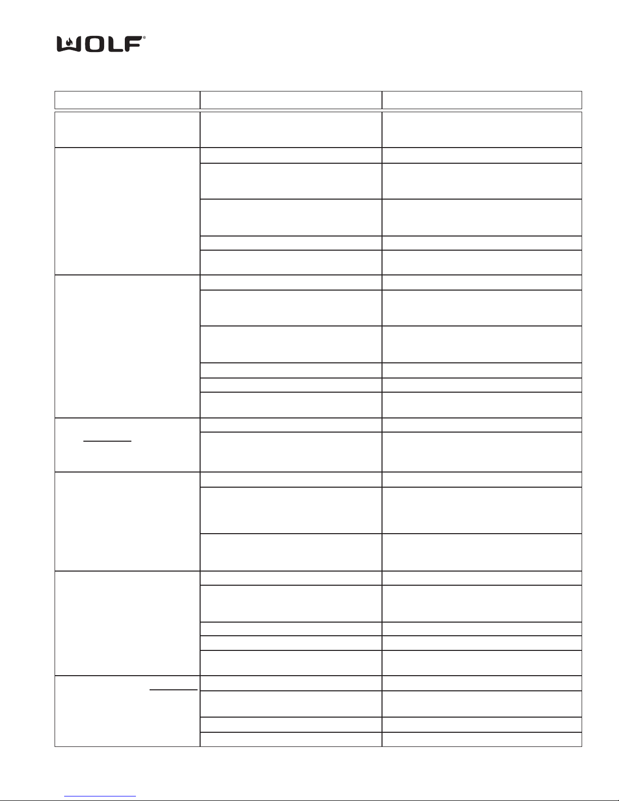
Troubleshooting Guide
5-9
DDuuaall FFuueell RRaannggee
PROBLEM POSSIBLE CAUSE TEST / ACTION
EE. LONG PREHEAT
FF. NO HEAT
GG. NO BROIL
HH. “CFH INDICATOR LIGHT
DOES NOT
LIGHT WHEN
TURNED TO COOKING
MODE
II. OVEN TEMPERATURE
TOO HIGH OR TOO LOW
JJ. TEMPERATURE PROBE
NOT WORKING
KK. COOLING FAN DOES NOT
WORK
LL. COOLING FAN NOISY
Defective hidden bake element
Loose or defective wire connection
Open element
Shorted element
Thermo Limiter open or tripped
Relay board failure
Loose or defective wire connection
Open element
Shorted element
Open or Shorted RTD
Thermo Limiter open or tripped
Relay board failure
Oven cavity too hot
Loose or defective wire connections from
ECH to “CFH” LED
Defective LED
Customer using wrong temperature
User Preference Offset (UPO) miscalibrated
Defective RTD Sensor
Wrong cooking mode for probe
Probe not inserted all the way into the
receptacle
Loose or defective wiring
Defective probe switch
Defective probe
Loose or defective wiring
Defective cooling fan
Air diverter bracket loose
Defective cooling fan motor
Check for error codes in diagnostic mode.
Perform element testing procedure in diagnostic
mode
Repair or replace wire connections or wires
Check for error codes in diagnostic mode.
Perform element testing procedure. Replace if
defective
Check for error codes in diagnostic mode.
Perform element testing procedure. Replace if
defective
Ohm limit, replace if defective. Reset limit
Perform relay board testing procedure.
Replace if defective
Repair or replace wire connections or wires
Check for error codes in diagnostic mode.
Perform element testing procedure. Replace if
defective
Check for error codes in diagnostic mode.
Perform element testing procedure. Replace if
defective
Initiate diagnostic mode, check for error codes
Ohm limit, replace if defective. Reset limit
Perform relay board testing procedure.
Replace if defective
Open oven door to cool oven cavity
Check wire connections. Repair/replace wire(s)
Defective ECH. Replace ECH
Replace “CFH” LED
Refer to Use/Care Guide for operation
Check UPO setting. Before making any temperature changes to UPO, check oven temperature with thermometer. UPO setting can be
±35°F.
Ohm RTD sensor, check technical data for correct ohm reading. Replace if defective. If RTD
good, replace oven controller
Refer to Use/Care Guide for operation
Check for error codes in diagnostic mode.
Insert probe into receptacle first before initiating
diagnostic mode
Repair or replace wiring
Replace probe switch
Ohm probe, check technical data for correct
ohm reading. Replace if defective
Repair or replace wiring
Check for error codes in diagnostic mode.
Replace if defective
Tighten air diverter bracket screws
Replace cooling fan
Problems Associated with the Oven
Page 72
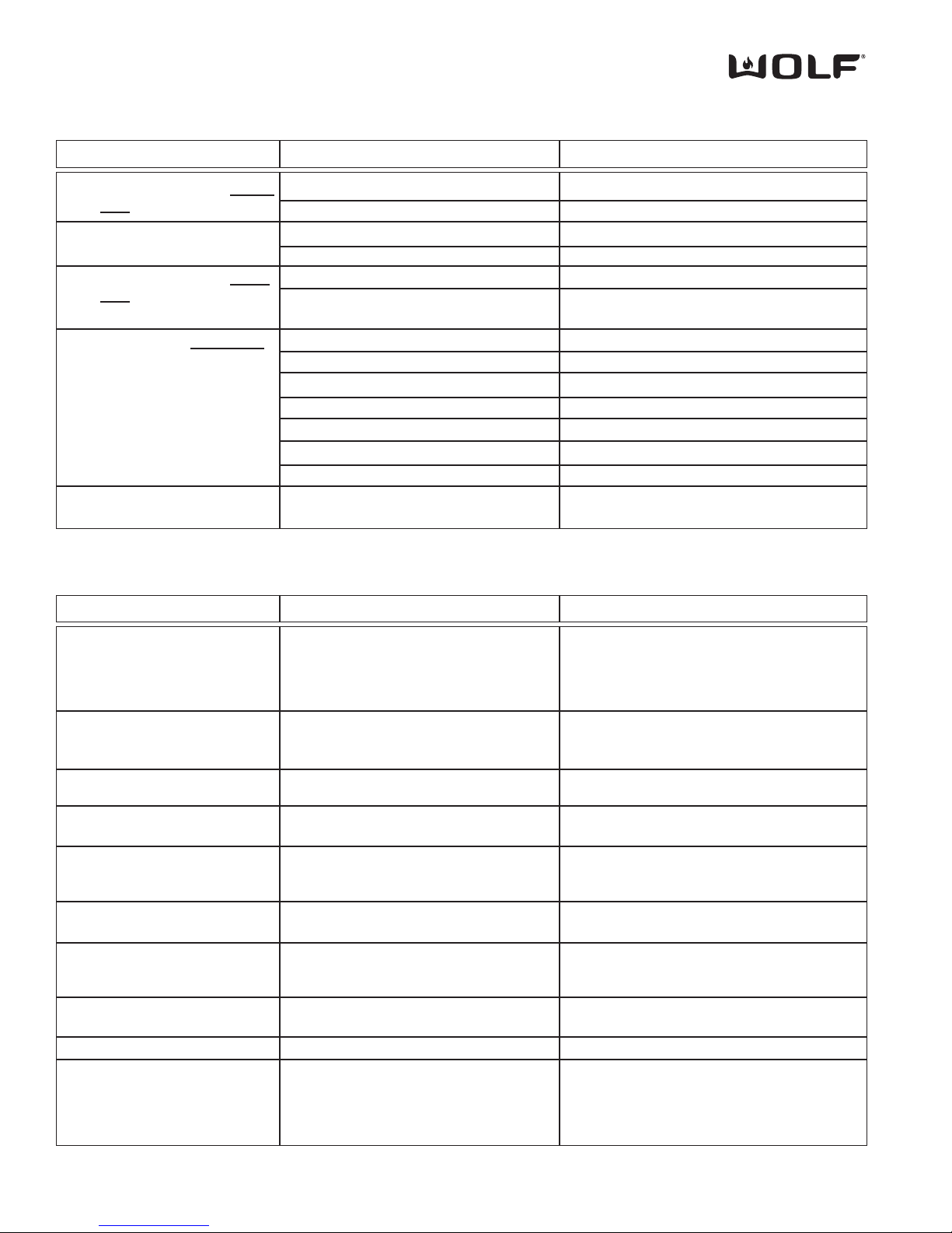
DDuuaall FFuueell RRaannggee
Troubleshooting Guide
5-10
PROBLEM POSSIBLE CAUSE TEST / ACTION
MM. CONVECTION FAN DOES
NOT WORK
NN. NOISY CONVECTION FAN
OO. CONVECTION FAN DOES
NOT SHUT OFF WHEN
OVEN DOOR OPEN
PP. OVEN LIGHT DOES NOT
WORK
QQ. DOOR WILL NOT LOCK
IN SELF-CLEAN MODE
Loose or defective wire connection
Defective convection motor
Fan blade out of balance
Loose fan blade
Unit in sabbath feature
Defective door switch
Defective bulb (if only one bulb out)
Defective fuse (if both bulbs out)
Loose or defective wiring
Defective door switch (if both bulbs out)
Defective key pad (if both bulbs out)
Defective transformer (if both bulbs out)
Loose or defective wiring
Defective motorized door latch assembly
Repair or replace wiring
Replace convection fan assembly
Replace convection motor assembly
Tighten nut for fan blade
Turn oven bezel to OFF to exit
Ohm door switch and motor. Replace motorized door latch assembly if defective
Replace bulb
Test fuse and replace if it is bad
Repair or replace wiring
Replace motorized door latch assembly
Replace ECH
Replace transformer
Repair or replace wiring
Ohm switches and motor. Replace if defective
Problems Associated with the Oven
ERROR CODE POSSIBLE CAUSE TEST / ACTION
01
02
03
04
07
08
09
0B
0C
0E
Door Lock or Unlock Switches not sensed
within 60 seconds while driving the door
lock motor
Over temperature occurs when the oven
reaches a temperature of 630 °F for an
unlocked door and 950°F for a locked door
Open circuit detected on RTD Oven Sensor
Shorted circuit detected on the RTD Sensor
SPI Communication lost from ECH to the
Control Board as reported by Control Board
EEPROM checksum is incorrect. Checked
at power up
Meat probe being sensed as shorted
Analog to Digital error during calibration
phase
Communication lost with oven controller
Power relay shorted, sensed as closed
when should be open
Failure of element circuit
Failure of relay drive circuitry
Perform motorized door lock test procedure in
diagnostic mode
Ohm door lock switches. Replace MDL (Motor
Door Lock) Assembly if defective
Ohm RTD sensor, replace if defective. If RTD
good replace oven controller.
Ohm RTD sensor, replace if defective. If RTD
good replace oven controller.
Ohm RTD sensor, replace if defective. If RTD
good replace oven controller.
Code reflects that the ECH cannot fine the
Control Board. Replace cable first. Replace
ECH if replacing cable does not correct problem
Replace oven controller
Initiated diagnostic mode and check meat
probe. Ohm meat probe, check reading with
Tech Data
Replace oven controller
Replace oven controller
Replace relay board
Replace relay board
Replace relay board
Problems Associated with Error Codes
Page 73
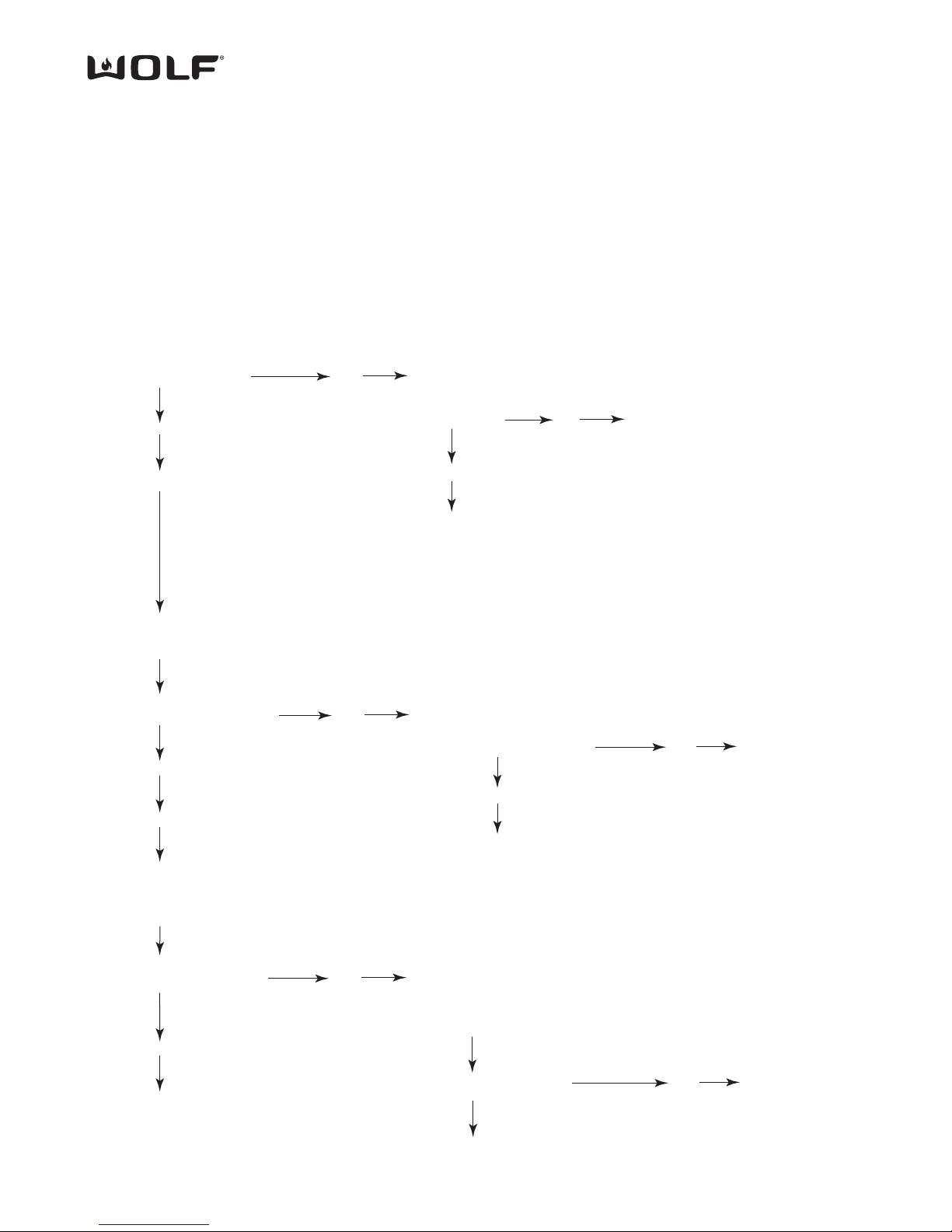
Troubleshooting Guide
5-11
DDuuaall FFuueell RRaannggee
ECH TROUBLESHOOTING FLOW CHART
Step 4. Testing Voltage at ECH (Electronic Conrol Housing)
Using a volt/ohm meter set to read DC voltage, at the J1 connector, place one meter probe to pin 1 and one meter
probe to pin 2.
Do you have 30 to 34 VDC
at J1 from pin 1 to pin 2?
Yes
Replace ECH
No
Unplug wire harness from ECH to oven
controller. Now, reconnect wire harnes
to ECH and oven controller making sure
to get good connection.
No
Is display working now?
Yes, problem fixed
Replace wire harness
Step 3. Testing Voltage at Oven Controller
Using a volt/ohm meter set to read DC voltage, at the J11A connector, place one meter probe to pin 1 and one meter probe to pin2.
Do you have 30 to 34 VDC
at J11A from pin 1 to pin 2?
Yes
No
Remove wire harness from J11A to J1.
Measure continuity of all wires. Do you
have continuity on all wires?
Yes
No
Replace wire harness
Replace relay board.
Go to step 4
Step 2. Testing Voltage on Relay Board
Using a volt/ohm meter set to read AC voltage, place one meter probe to E1 (L1) and one meter probe to E2 (N).
Do you have 120 VAC
from E1 (L1) to E2 (N)?
Yes
No
Check voltage at unit terminal block at L1 and N.
Do you have 110 to120 VAC
from L1 to N?
Yes
Unit has loose or defective wire(s) between L1 of
terminal block and E1(L1) on relay board or N of
terminal block and E2 (N) on relay board.
Repair/Replace wires.
Go to step 3
No
Check for loose or defective wiring to unit
from terminal block to junction box/power
cord. May have to call an electrician
Step 1. Testing Wire Connections
Check wire connections at J4 connector on oven controller
to J1 connector of relay board, unplug both ends and reseat.
Check wire connections at J11A connector on oven controller
to J1 connector on ECH, unplug both ends and reseat.
Check wire connections at E1 (L1) and E2 (N) connector on
relay board, unplug both ends and reseat.
Page 74

DDuuaall FFuueell RRaannggee
Troubleshooting Guide
5-12
Step 1.
Testing Supply Voltage for DSI Board
Using a volt/ohm meter set to read AC voltage, place one meter probe to pin 4 and one meter probe to pin 10 on the J1 connector of the DSI board.
Do you have 120 VAC
from Pin 4 to Pin 10?
Yes
Go to step 2
No
Do you have 110 to120 VAC at the Power
Input connector on L1 and N?
Yes
No
Disconnect power to unit.
Then, check connections from
DSI Board to Power Input, for
loose connections. If loose
connection, reseat connectors.
If connections okay, replace J1
cable harness.
Check for 110 to 120VAC at unit
terminal block from L2 to N.
120 VAC present?
Yes
Disconnect power to unit.
Check wiring between unit
terminal block and Power
Input connector for loose
or defective wire(s) and
repair / replace.
No
Checked for defective
or loose wiring to unit
terminal block from
junction block, may
have to call an electrician.
Step 2.
Testing Griddle Thermostat
Using a volt/ohm meter set to read AC voltage, place one meter probe to pin 6 and one meter probe to pin 4 on the J1 connector of the DSI board.
Do you have 110 to120 VAC
from Pin 6 to Pin 4 with
thermostat turned on?
Yes
Go to step 3
Disconnect power to unit.
Unplug J1 connector at DSI board.
Check for continuity across
contacts on griddle thermostat
Pins 6 & 10 with thermostat on.
Replace thermostat if open.
Then griddle thermostat
is working okay.
Step 3.
Testing DC Voltage for Solenoid Output
Using a volt/ohm meter set to read DC voltage, place one meter probe to pin 1 and one meter probe to pin 2 on the J1 connector of the DSI board.
Do you have 10 VDC
from Pin 1 to Pin 2?
No
Go to step 4
Yes
Disconnect power to unit.
Unplug J1 connector at DSI board.
Ohm wires at pin 1 and pin 2. If no
ohm reading, check for loose or
defective wire(s), repair/replace if
defective. If wire(s) okay replace
defective solenoid.
Step 4.
Testing Continuity of J2/GND Wire for DSI Board
Disconnect power to unit. Disconnect wire at J2/GND connection.
Do you have continuity from
J2/GND wire connector to
unit chassis?
Yes
Go to step 5
Repair/replace defective J2/GND
wire.
Step 5.
Testing Continuity of Griddle/FT Electrode for DSI Board
Disconnect power to unit. Disconnect wire at J4 connection.
Do you have continuity
from J4 wire connector
to tip of griddle/FT electrode?
No
No
Replace defective DSI Board
Yes
DSI BOARD TROUBLESHOOTING FLOW CHART
DSI BOARD TROUBLESHOOTING FLOW CHART
Page 75
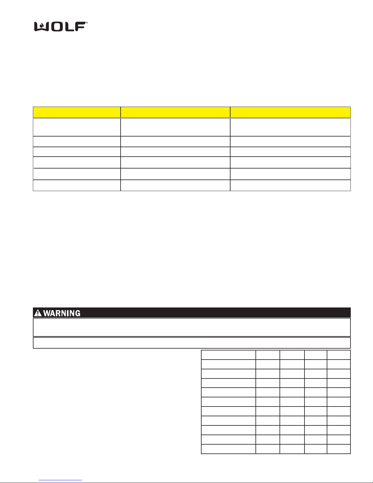
Oven Selector Switch Test
Troubleshooting Guide
5-13
DDuuaall FFuueell RRaannggee
TESTING THE OVEN RELAY BOARD
Element Testing
First access diagnostic mode. Once in diagnostic mode, the technician can turn the oven control knob bezel to activate an element. The element relay and the double line breaker(dlb) will close to complete a 240/208 VAC circuit
through a specific element. If the oven controller detects the current running through the closed circuit, the **CFH light
will be illuminated.
NOTE: Diagnostic Mode will end 2 minutes after last key stroke or when the CLEAR key is pressed.
** Call For Heat
RTD Testing
First access Diagnostic Mode. Once in diagnostic mode, the RTD temperature is shown in display window of temperature control knob. If the RTD is open, “Err 03” will be shown in the display of the electronic control housing. If the
RTD is shorted, “Err 04” will be shown in the display of the electronic control housing.
NOTE: Diagnostic mode will end 2 minutes after last key stroke or when the ENTER key is pressed.
Probe Testing
First access Diagnostic Mode. Next, press the PROBE key (this will switch the readout to probe temperature as shown
in the display window of the temperature control knob). If the probe has not been inserted, “out” will be shown as the
probe temperature in the display window of the temperature control knob. If the probe is shorted, “Err 09” will be shown
in the display of the electronic control housing.
NOTE: Diagnostic Mode will end 2 minutes after last key stroke or when the ENTER key is pressed.
Turn Bezel (Cooking Mode) Relay(s) Activated Response
Stone
(Use “PROOF” for 18” Cavity)
Clean
Conv
Conv Roast
Conv Broil
Conv Bake
Left Convection Element
Right Convection Element
Bake Stone Element
(must be plugged in)
Inner Bake Element
Broil Element
Outer Bake Element
**CFH Indicator Light Illuminates
**CFH Indicator Light Illuminates
**CFH Indicator Light Illuminates
**CFH Indicator Light Illuminates
**CFH Indicator Light Illuminates
**CFH Indicator Light Illuminates
Switch Position Pin 7 Pin 8 Pin 9 Pin 10
OFF
Conv. Bake X
Conv. Broil X X
Conv. Roast X
Convection X X
Self Clean X X X
Stone X X
Roast X X X
Broil X X
Bake X
The chart to the right can be used to verify proper
functionality of the oven selector switch. Use an Ohm
Meter to perform these continuity tests.
The wire harness must be disconnected from the
ECH assembly to prevent inaccurate readings.
As you rotate the switch to the position of the chart
you should find continuity between Pin 6 and the pins
marked with an “X”.
TO AVOID ELECTRICAL SHOCK, POWER TO THE UNIT MUST BE DISCONNECTED BEFORE PERFORMING
THE FOLLOWING TESTS.
Page 76
DDuuaall FFuueell RRaannggee
Troubleshooting Guide
5-14
Fans and Motors
First access diagnostic mode. Once in diagnostic mode, the technician can turn the oven control knob bezel or press a key on
the Electronic Control Housing to activate a fan or a motor. The fan and motor relays will close to complete a 120 VAC circuit
through a specific fan or motor. If the oven controller detects the functionality through switches, the **CFH indicator light will be
illuminated
.
NOTE: Diagnostic mode will end 2 minutes after last key stroke or when the ENTER key is pressed.
Turn Bezel
(Cooking Mode)
or
Press Key on Electronic
Control Housing
Relay(s) Activated
Response
Broil
Roast
Bake
Cook Time
Stop Time
Clock
NOTE: For DF48 and
DF60 “CLOCK” cycles
left MDL. Use “TIMER”
to cycle right MDL.
Probe
Clear
Enter
Right Convection Fan
Left Convection Fan
and 18” cavity convection fan
Oven Light
Low Cooling Fan
High Cooling Fan
Motor Door Lock
(MDL)
Probe
Right Convection fan ON
Left Convection Fan ON
Oven Light Turns On
Cooling Fan On At Low Speed
Cooling Fan On At High Speed
“A” Icon Appears
No Icon in Display
“P” Icon Appears
Meat Probe Temperature is
Shown in Display Window of
Temperature Control Knob
Clears All Stored Errors from
EEPROM
Exits Diagnostic Mode
Action
Right Convection Fan
Turns ON
Left Convection Fan
Turns ON
Activates Oven Lights
Cooling Fan Turns ON
Cooling Fan Turns ON
MDL Switch in Closed
Position
MDL Switch in
Transition
MDL Switch in open
Position
Ohm Testing Elements at Relay Board
This procedure will allow the service technician to ohm any of the elements directly at the relay board.
At the relay board, pull the wire off of the terminal DLB/E11. This is done to keep from ohming the relay board. It does not take
the Thermo limiter out of the equation, but if the technician DOES NOT get an ohm reading from the DLB lead to all of the element leads, then, there is a problem with the Thermo Limiter.
Right Convection Element: PR5/E9 to DLB/E11 wire
Left Convection Element: PR2/E5 to DLB/E11 wire
Outer Bake Element: PR4/E8 to DLB/E11 wire
Inner Bake Element: PR3/E6 to DLB/E11 wire
Bake Stone Element: PR6/E10 to DLB/E11 wire
Broil Element: PR1/E4 to DLB/E11 wire
TO AVOID ELECTRICAL SHOCK, POWER TO THE UNIT MUST BE DISCONNECTED BEFORE PERFORMING
THE FOLLOWING TEST.
Page 77

Technical Data
DDuuaall FFuueell RRaannggee
6-1
SECTION 6
TECHNICAL DATA
Page 78
DDuuaall FFuueell RRaannggee
Technical Data
6-2
Technical Data Chart
Part Description
Voltage Ohms
Part Number
Motorized Latch
Temperature Sensor
Oven Light
Element, Convection
Element, Convection
Fan, Convection CCW
Fan, Convection CW
Element, Bake-18”
Element, Bake-18”
Element, Bake Outer-30”, 36”
Element, Bake Inner-30”, 36”
Element, Bake Outer-30”, 36”
Element, Bake Inner-30”, 36”
Cooling Fan
Meat Probe
Element, Bake Stone
Element, Bake Stone
Transformer
Element, Broil 18”
Element, Broil 18”
Element, Broil 30”
Element, Broil 30”
Element, Broil 36”
Element, Broil 36”
Solenoid, Single
120
12
240
208
120
120
240
208
240
240
208
208
120
240
208
120 to 12
240
208
240
208
240
208
10
2900
1091 @ 75°F
.6
24
24
8.8
8.8
39.7
39.7
1
57.6
48
57.6
48
HI 9.7 / LO 12.8
34,000 @ 90°F
16.4
16.4
28.8
28.2
16
16
14.4
14.4
185 to 215
4
20
2400
1803
55
55
1450
1082
1000
1200
750
900
65
3500
2640
40
2000
1500
3600
2704
4000
3004
802257
800306
800307
800699
800701
802012
802012
804152
801143
800529
800717
800950
802071
801120
801615
802089
Amperage Watts
1 to 2
10
8.7
.46
.46
6.04
5.2
4.166
5
3.6
4.33
14.6
12.7
3.33
8.33
7.2
15
13
16.6
14.4
NOTE: Actual readings may vary by ±10%
Page 79
Part Description
Orifice Size
Metric Marking
Part Number
Burner Valve, Lg, Nat
Burner Valve, Sml, Nat
Burner Valve, Lg, LP
Burner Valve, Sml, LP
Jet Holder, Lg, Nat w/orifice
Jet Holder, Lg, LP w/orifice
French Top Jet Holder, Nat
French Top Jet Holder, LP
Jet Holder, Sml, Nat w/orifice
Jet Holder, Sml, LP w/orifice
Outer Dist. Ring, Sml, Nat w/orifice
Outer Dist Ring, Sml, LP w/orifice
Outer Dist. Ring, Lg, Nat w/orifice
Outer Dist. Ring, Lg, LP w/orifice
Char-Broiler IR Orifice, Nat
Char-Broiler IR Orifice, LP
Griddle IR Orifice, Nat
Griddle IR Orifice, LP
Simmer Bypass 0.62 62
Main Bypass 0.97 97
Simmer Bypass 0.60 60
Main Bypass 0.57 57
Simmer Bypass 0.39 39
Main Bypass 0.6 60
Simmer Bypass 0.39 39
Main Bypass 0.46 46
Main 1.78 178
Main 1.15 115
1.78 178
1.15 115
Main 1.4 140
Main 0.91 91
Simmer 0.63 J
Simmer 0.37 G
Simmer 0.90 S
Simmer 0.57 P
0.50 50
0.57 57
0.51 51
0.57 57
802018
804349
802400
808015
802404
802405
802250
802275
805730
805729
800470
802679
802398
802276
800837
801011
800838
801011
Orifice Quick Reference Chart - PTS 17000000
Technical Data
DDuuaall FFuueell RRaannggee
6-3
Part Description
Orifice Size
Part# Size Marking
Part Number
Burner Valve, 15K, Nat
Burner Valve, 15K, LP
Burner Valve, 9.2K, Nat
Burner Valve, 9.2K, LP
Orifice Holder, 15K, Nat
Orifice Holder, 15K, LP
Orifice Holder, 9.2K, Nat
Orifice Holder, 9.2K, LP
Orifice Holder, FT, Nat
Orifice Holder, FT, LP
Orifice Char IR, Nat
Orifice Char IR, LP
Orifice Griddle IR, Nat
Orifice Griddle IR, LP
Simmer 804128 .62 mm 62
Main 809495 .67 mm 67
Simmer 809493 .43 mm 43
Main 809493 .43 mm 43
Simmer 809493 .43 mm 43
Main 800054 .54 mm 54
Simmer 801322 .33 mm 33
Main 800893 .34 mm 34
Simmer 809485 .79 mm 79
Main 809484 1.80 mm 180
Simmer 809479 .47 mm 47
Main 809743 1.17 mm 117
Simmer 809482 .65 mm 65
Main 809481 1.40 mm 140
Simmer 809477 .41 mm 41
Main 809476 .93 mm 93
Main 809484 1.80 mm 178
Main 809743 1.17 mm 117
800837 0.070 in. 50
801011 0.043 in. 57
800838 0.067 in. 51
801011 0.043 in. 57
808016
808017
808014
808015
809781
809752
808000
808001
802250
802275
Orifice Quick Reference Chart - SWS 17000000
Page 80
DDuuaall FFuueell RRaannggee
Technical Data
6-4
Operation Time Chart (Convection Fans May Operate in Preheat)
Bake
Broil
Roast
Bake Stone
Convection
Convection Roast
Convection Broil
Convection Bake
Outer
Inner
Broil
Broil
Outer
Inner
Broil
Broil
Bake
Left Convection
Right Convection
Broil
Left Convection
Right Convection
Broil
Outer
Inner
Left Convection
Right Convection
60%
32%
10%
100%
70%
50%
37%
63%
30%
42%
58%
55%
55%
17%
47%
47%
100%
70%
50%
8%
20%
57%
57%
None
None
None
Left - 43%
Right - 38%
Left - 55%
Right - 55%
Left - 100%
Right - 100%
Left - 100%
Right - 100%
Left - 57%
Right - 57%
Mode Element(s) Operation Time Convection Fan
Operation Time Chart
Mode Elements Operation Time Duration
Self Clean
Stage 1-
Outer
Inner
Broil
Stage 2 -
Outer
Inner
Broil
33%
66%
66%
33%
66%
66%
12 minutes
Until Oven Reaches 850°F
NOTE: Door locks at start of Self-Clean. Unlocks at 300°F.
Cooling Fan Operational Temperatures
Lo Speed - ON @ 225°F Lo Speed - OFF @ 175°F
High Speed - ON @ 430°F High Speed - OFF @ 380°F
Oven OFF - Cooling Fan turns OFF @ 300°F
Mode Temp. 240V 208V 240V 208V
30” / 36” 30” / 36” 18” 18” NOTE:
Bake 350 °F 13 min. 15 min. 16 min. 21 min. Preheat
Convection Bake 375 °F 15 min. 27 min. 18 min. 29 min. times are
Convection Roast 325 °F 13 min. 19 min. 18 min. 23 min. approx.
Convection 325 °F 18 min. 23 min. 16 min. 20 min.
Roast 350 °F 13 min. 17 min. 20 min. 26 min.
Bake Stone 400 °F 24 min. 32 min. n/a n/a
Preheat Times
Page 81

Wiring Diagrams
DDuuaall FFuueell RRaannggeess
7-1
WIRING
DIAGRAMS
SECTIO
N 7
Page 82
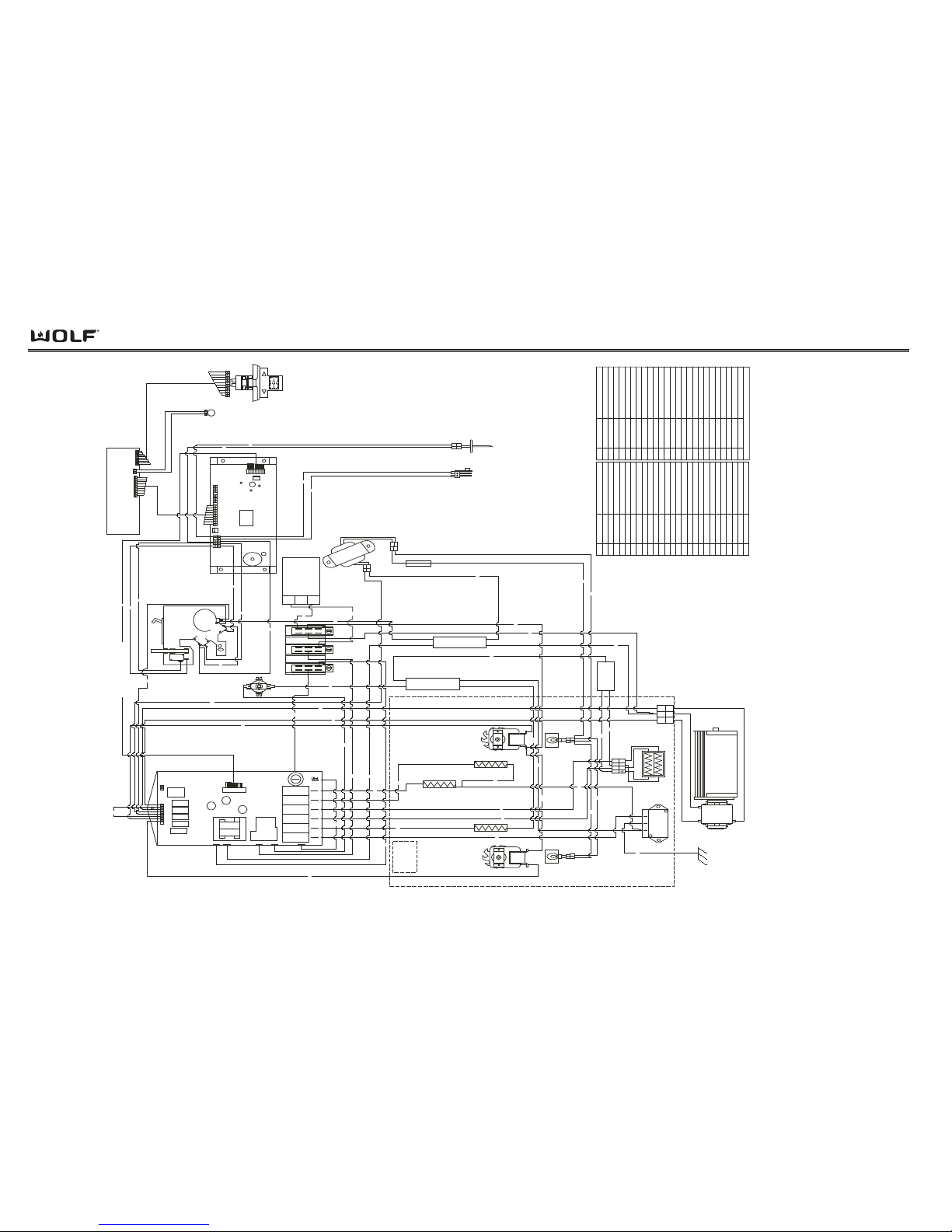
Wiring Diagrams
DDuuaall FFuueell RRaannggee
7-2
Outer Bake Element
Inner Bake Element
L2 splice
Bi-metal
Cutout
Right Convection Element
Broil Element
Left Convection Element
splice
Cooling Fan
1 2 3
RTD
neutral splice
AMP
CONNECTOR
Mates with
Rangetop
1
3
fuse
Wiring Diagram
Models:
DF 304, DF 366,
DF 364C, DF 364G
Backview
Oven
Relay Board
8 7 6 5 4 3 2 1
J3 J2
1 2
J1
L1
NEU
L2
DLB
L1-B
E14
PR6 PR5
PR4
PR3
PR2 PR1
NL2
Terminal Block
L1
Motor Door
Lock Assembly
Door
Switch
Switch
Unlatch
Latch
Switch
Motor
ECH to KNOB Harness
ECH
Display
LO
HI
Electronic Temp Knob
Selector Switch
and
30 / 36 Oven Control
to ECH Harness
13
Oven Controller
15
610
J2
Meat
Probe
Receptacle
1
2
1
2
Light
T
r
a
n
s
f
o
r
m
e
r
Element
Receptacle
Bake Stone
Right
12
Oven
Light
Left
Oven
12
Light
Convection
Fan
Left
Right
Convection
Fan
234
321
1
1
2
2
1
1 12 2
of
19
29
28
21
22
23
30
27
26
25
24
11
13
18
17
15
14
1
2
6
8
10
9
16
3
5
4
36
37
34
49
48
50
42
12
7
45
44
43
46
47
51
40
1 2 3
38
31
20
32
35
41
39
LED
Indicator
Light
33
Relay Board to Oven Controller (22 wires)
WIRE W IRE COLOR INFO
1
Gray
Meat Probe
2
Gray/Black DST
Meat Probe
3
Brown/Black DST
MDL switch Common
4
Brown
MDL switch Unlocked
5
Purple
MDL switch Locked
6
Tan
RTD
7
Black
Relay Board
to
Oven Control
(22 wires)
8
Tan/Black DST
RTD
9
Yellow
Door Switc h
10
Yellow/Black DST
Door Switc h
11
Black/White DST
High Fan
12
Black
Relay Board Jumper
13
Lt. Blue
Low Fan
14
Black/White HA
Trans forme r
15
Gray/Black HA
MDL L1
16
Purple/Black DST
MDL Switch Common
17
Orange
Left Convection Fan
18
Blue
Right Convection Fan
19
Black
L1 Logic
20
White
N Logic
21
Red
L2
22
Red
DLB to Bi-metal cutout
23
Black
L1 Board Jumper
24
Black/Purple DST
Bake Stone
25
Black/Blue DST
Right Convection Element
26
Black/Green DST
Outer Bake
27
Black/Yellow DST
Inner Bake
28
Black/Orange DST
Left Convection Element
29
Black/Red DST
Broil
30
Black
L1 Relays
31
White
N Splice to Cool Fan N
32
White
Splice to Transformer N
33
White
Splice to MDL N
34
Red
Transformer to Light Fuse
35
Blue
Transformer to Light
36
Red
Light to Light
37
Blue
Light to Light 2
38
White
Cool Fan Neutral
39
Red Range Top L2
40
Red
L2 Jumper
41
White
Rangetop N
42
Red
TCO to Splice L2
43
Red
Splice to Splice L2
44
Red
Splice to Saber 2 L2
45
Red
Splice to Saber 4 L2
46
Red
Splice to RCE L2
47
Red
Splice to Bake Stone L2
48
Left Convection Fan N
49
White
Right Convection Fan N
50
Green
Ground
51
Red
Broil L2
NOTE: DST Indicates a color to double stripe the wire
White
WIRE W IRE COLOR
INFO
Page 83
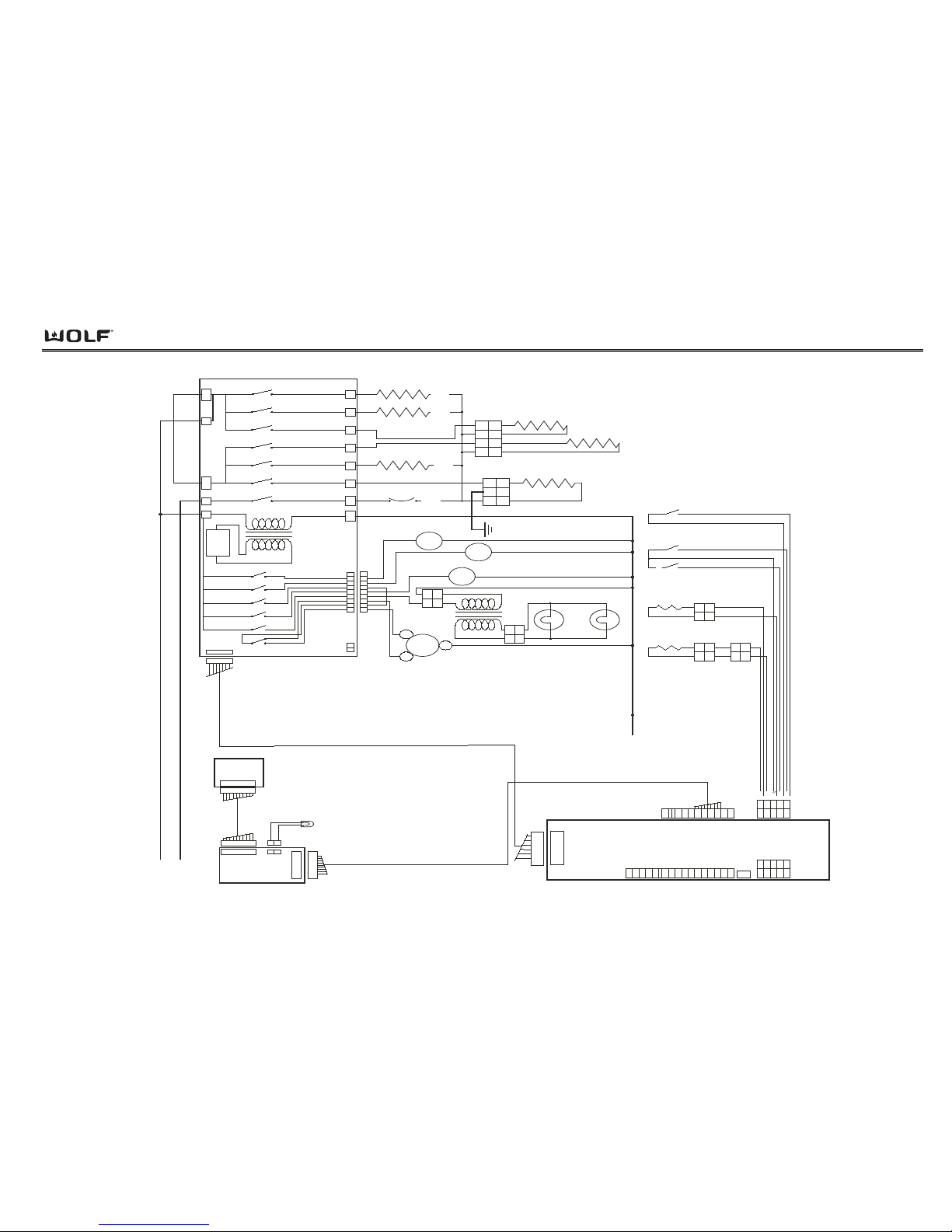
Wiring Diagrams
DDuuaall FFuueell RRaannggeess
7-3
L1
L2
Oven
Relay
Board
K1
NO
K2
NO
K3
K4
K5
K6
NONONONO
K7
NO
K14
1
22
1
22
12
3
45
6
78
9
1
1234
13
Molex Sabre
Connector
Pizza
Element
Receptacle
Pizza El.
3500W
240V
Outer Bake El.
1650W
240V
Inner Bake El.
1850W
240V
30"/36" Broil El.
3600W/4000W
240V
R Cvt El.
2400W
240V
L Cvt El
2400W
240V
Bi-metal
Thermal
Cutout
1
LOW
HI
L.Cvt
Fan
R. Cvt
Fan
Motor
Door
Lock
20W Oven Light
20W Oven Light
NEUTRAL
1
1
22
22
1
3
19
1
2
345
6
7
8
9
123456897
G
GND
123
445
689
10
12345
689
10
1
6
10
295
8
12
Meat
Probe
Sensor
Meat
Probe
Receptical
J2
RTD
Sensor
12
Molex
Connector
12
21
Amp
Connector
MDL
Unlatched
Switch
MDL
Latched
Switch
Door
Switch
1 2
12
2 pin
Amp Conn.
2 pin
Amp
Conn
1
1
2
2
1234
30 " & 36" Dual Fuel Oven
Schematic Diagram
L1
L1
L2 L1-B L1-A
Oven
Controller
Dual
Fuel
ECH
NEU DLB Pr6 Pr5 Pr4 Pr3 Pr2 Pr1
J11A
J11B
J4
J1
NO
NO
NO
K9K10
K11K12K13
NONONONONO
NO
12345
6
789
J3J2
2
12
12
LED Indicator
Light
19
110
110
Mode/
Temp
Knob
110
110
Relay
Board
Logic
Cooling
Fan
Motor
Page 84
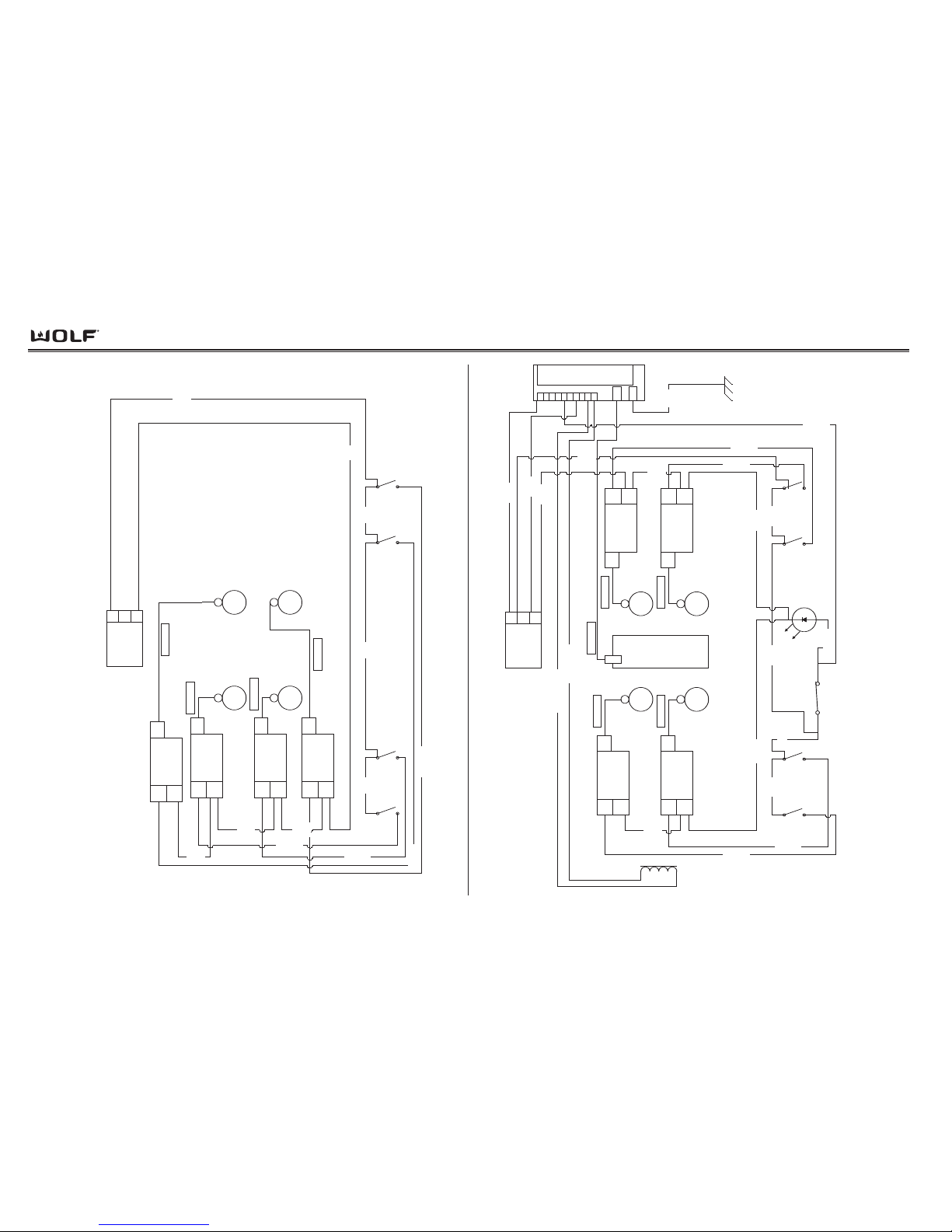
POWER INPUT
AMP
CONNECTOR
N
3
L1
1
RIGHT
FRONT
SWITCH
RIGHT
REAR
SWITCH
LEFT
FRONT
SWITCH
LEFT
REAR
SWITCH
LEFT
REAR
LEFT
FRONT
RIGHT
FRONT
RIGHT
REAR
LEFT FRONT
SPARK MODULE
L1
N
spark
lead
LEFT REAR
SPARK MODULE
L1
N
spark
lead
2
Wht
11
Wht
1
Bk
3 Bk5 Bk
6 Bk/Red
9
Bk/
Tan
8
Bk/
Gy
7 Bk
sparker wire
sparker wire
Dual Fuel Rangetop Harness
Model DF304
RIGHT FRONT
SPARK MODULE
L1
N
spark
lead
10
Wht
RIGHT REAR
SPARK MODULE
L1
N
spark
lead
12
Wht
sparker wire
sparker wire
4 Bk/Y
POWER INPUT
AMP
CONNECTOR
N
3
L1
1
RIGHT
FRONT
SWITCH
RIGHT
REAR
SWITCH
LEFT
FRONT
SWITCH
LEFT
REAR
SWITCH
LEFT
REAR
LEFT
FRONT
RIGHT
FRONT
RIGHT
REAR
LEFT FRONT
SPARK MODULE
L1
N
spark
lead
LEFT REAR
SPARK MODULE
L1
N
spark
lead
RIGHT REAR
SPARK MODULE
L1
N
spark
lead
RIGHT FRONT
SPARK MODULE
L1
N
spark
lead
sparker wire
sparker wire
sparker wire sparker wire
Dual Fuel Rangetop Harness
Model DF364G
Griddle
t
o
Griddle
120 VAC
INDICATOR
LIGHT, LED
10
J4
GND
987654321
DSI
SPARK
E
R
10VDC
GRIDDLE/
FRENCH TOP
Solenoid
4 Wht
6
Wht
21
Wht
2
Bk
10 Bk
9
Bk/
Red
7
Bk/
Y
20
Bk/
Tan
19
Bk/
Gy
17 Bk
8 Wht
1 Blk
3 Wht
5
Gn/Y
DST
11 Bk
16 Bk
15 Bk/O
14
Bk/
O
18 Wht
12 Wht/O Ha
13 Bk/O Ha
sparker wire
7-4
DDuuaall FFuueell RRaannggee
Wiring Diagrams
Page 85
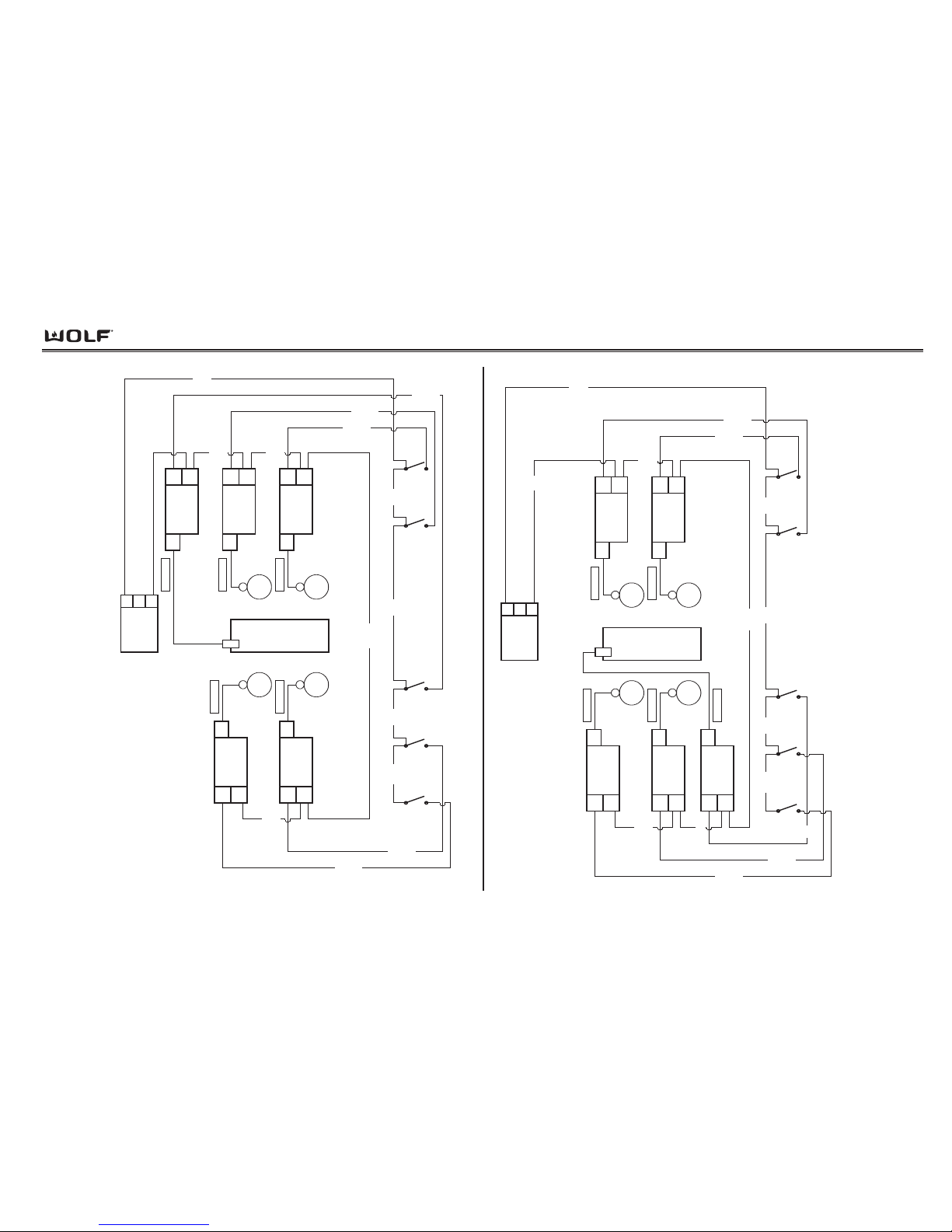
Wiring Diagrams
DDuuaall FFuueell RRaannggeess
7-5
POWER INPUT
AMP
CONNECTOR
N
3
L1
1
RIGHT
FRONT
SWITCH
RIGHT
REAR
SWITCH
MIDDLE
REAR
SWITCH
LEFT
FRONT
SWITCH
LEFT
REAR
SWITCH
LEFT
REAR
LEFT
FRONT
RIGHT
FRONT
RIGHT
REAR
LEFT FRONT
SPARK MODULE
L1
N
spark
lead
LEFT REAR
SPARK MODULE
L1
N
spark
lead
RIGHT REAR
SPARK MODULE
L1
N
spark
lead
RIGHT FRONT
SPARK MODULE
L1
N
spark
lead
MIDDLE FRONT
SPARK MODULE
L1
N
spark
lead
Wht
sparker wire
sparker wire
sparker wire sparker wire
Dual Fuel Rangetop Harness
Model DF364C
2
3
Wht
5
Wht
15
Wht
1
Bk
7 Bk9 Bk
6
Bk/
Red
4
Bk/
Y
11
Bk/
Or
14
Bk/
Tan
13
Bk/
Gy
10 Bk
12 Wht
8 Bk
sparker wire
CHAR-
BROILER
POWER INPUT
AMP
CONNECTOR
N
3
L1
1
RIGHT
FRONT
SWITCH
RIGHT
REAR
SWITCH
CHAR-
BROILER
SWITCH
LEFT
FRONT
SWITCH
LEFT
REAR
SWITCH
LEFT
REAR
LEFT
FRONT
RIGHT
FRONT
RIGHT
REAR
LEFT FRONT
SPARK MODULE
L1
N
spark
lead
LEFT REAR
SPARK MODULE
L1
N
spark
lead
RIGHT REAR
SPARK MODULE
L1
N
spark
lead
RIGHT FRONT
SPARK MODULE
L1
N
spark
lead
sparker wire
sparker wire
sparker wire sparker wire
Dual Fuel Rangetop Harness
Model DF364C
ALTERNATE CONSTRUCTION
MIDDLE REAR
SPARK MODULE
L1
N
spark
lead
2
Wht
3
Wht
15
Wht
1
Bk
7 Bk8 Bk9 Bk
6
Bk/
Red
4
Bk/
Y
11
Bk/
Or
14
Bk/
Tan
13
Bk/
Gy
10 Bk
12 Wht
5 Wht
CHAR-
BROILER
sparker wire
Page 86
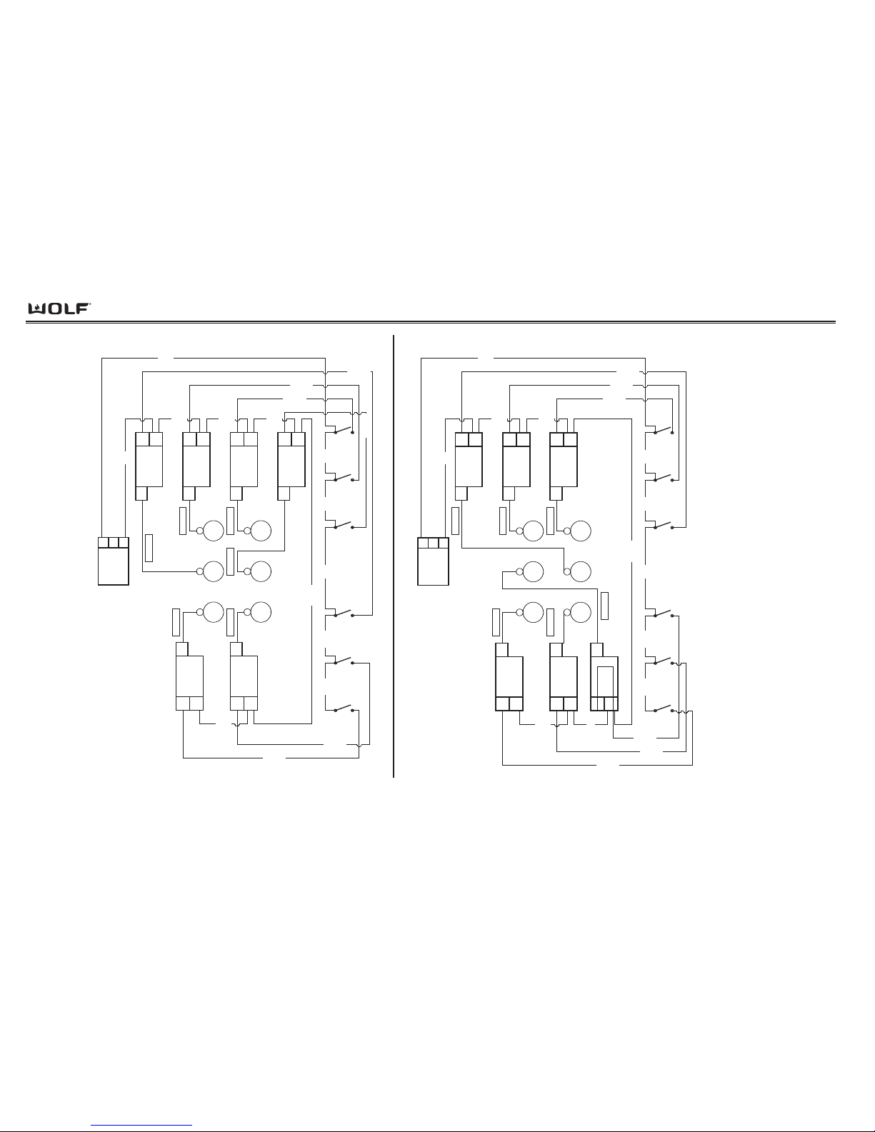
Wiring Diagrams
DDuuaall FFuueell RRaannggee
7-6
POWER INPUT
AMP
CONNECTOR
N
3
L1
1
RIGHT
FRONT
SWITCH
RIGHT
REAR
SWITCH
MIDDLE
FRONT
SWITCH
MIDDLE
REAR
SWITCH
LEFT
FRONT
SWITCH
LEFT
REAR
SWITCH
LEFT
REAR
MIDDLE
REAR
LEFT
FRONT
MIDDLE
FRONT
RIGHT
FRONT
RIGHT
REAR
LEFT FRONT
SPARK MODULE
L1
N
spark
lead
LEFT REAR
SPARK MODULE
L1
N
spark
lead
RIGHT REAR
SPARK MODULE
L1
N
spark
lead
MIDDLE REAR
SPARK MODULE
L1
N
spark
lead
RIGHT FRONT
SPARK MODULE
L1
N
spark
lead
MIDDLE FRONT
SPARK MODULE
L1
N
spark
lead
2
Wht
3
Wht
5
Wht
14
Wht
15 Wht
18
Wht
1
Bk
7 Bk8 Bk9 Bk12 Bk
6
Bk/
Red
4
Bk/
Y
10 Bk/Bl
11
Bk/
P
17
Bk/
Tan
16
Bk/
Gy
13 Bk
sparker wire
sparker wire
sparker wire
sparker wire sparker wire sparker wire
Dual Fuel Rangetop Harness
Model DF366
POWER INPUT
AMP
CONNECTOR
N
3
L1
1
RIGHT
FRONT
SWITCH
RIGHT
REAR
SWITCH
MIDDLE
FRONT
SWITCH
MIDDLE
REAR
SWITCH
LEFT
FRONT
SWITCH
LEFT
REAR
SWITCH
LEFT
REAR
MIDDLE
REAR
LEFT
FRONT
MIDDLE
FRONT
RIGHT
FRONT
RIGHT
REAR
LEFT FRONT
SPARK MODULE
L1
N
spark
lead
LEFT REAR
SPARK MODULE
L1
N
spark
lead
RIGHT REAR
SPARK MODULE
L1
N
spark
lead
MIDDLE FRONT
SPARK MODULE
L1
N
spark
lead
RIGHT FRONT
SPARK MODULE
L1
N
spark
lead
sparker wire
sparker wire
sparker wire sparker wire
MIDDLE REAR
SPARK MODULE
L1
N
spark
lead
sparker wire
sparker wire
Dual Fuel Rangetop Harness
Model DF366
ALTERNATE CONSTRUCTION
2
Wht
3
Wht
5
Wht
18
Wht
1
Bk
7 Bk8 Bk9 Bk12 Bk
6
Bk/
Red
4
Bk/
Y
10
Bk/
Bl
11
Bk/
P
17
Bk/
Tan
16
Bk/
Gy
13 Bk
15 Wht
14 Wht
Page 87
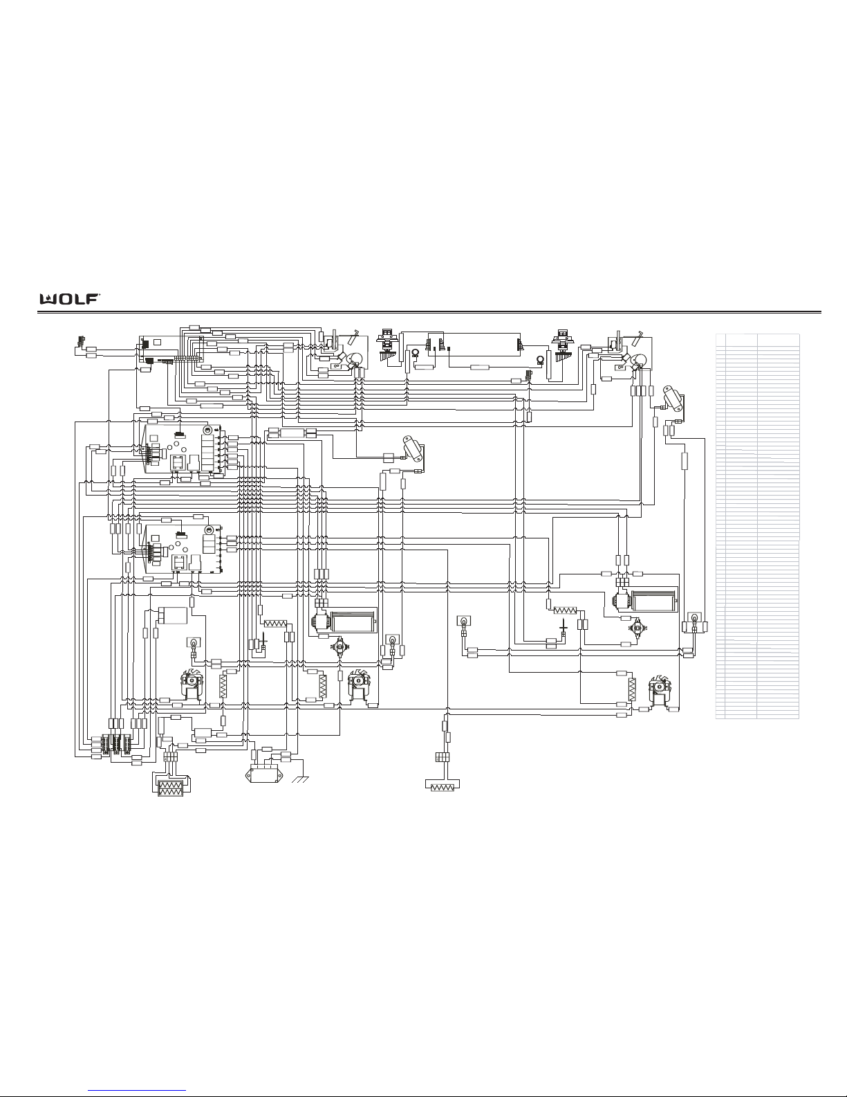
Wiring Diagrams
DDuuaall FFuueell RRaannggeess
W olf Appliance Co
mpany, L LC
48" D iagr am Ove
n
Wirin
g D iagr am
Wo
lf # 804345A R evison A
Mode
ls
DF 486C, DF486-L P, D F486G, DF 486-LP ,
DF 484CG, D F484CG-L P , DF 484DG, DF 4
84DG-LP
DF 484DC, DF484DC-L P , DF 484F, D F48
4F -LP
L2 Splice
Righ
t
Con
vect
io
n
Eleme
n
t
Broi
l Elem
e
n
t
L
e
ft Con
vect
ion
Eleme
n
t
23
4
3
2
1
1
P
izza
E
lement
Receptacle
1
1
2
2
Terminal
Block
LOHI
AM
P
CO
NNEC
TO
R
Mate
s
wi
th
Ra
n
g
etop
1
3
L
2
splice
1
1
2
2
L
ig
h
t
T
ran
sf
o
rme
r
1
1
1
1
2
2
2
2
L
ig
ht
Transf
ormer
1
1
1
1
2
2
2
2
R
elay B oard
1
1
2
2
Unlatched
Switch
Latched
Switch
D
o
o
r
S
w
i
t
c
h
Motor Door
Lock
234
321
1
3
0" Cooling
Fan
1
1
2
2
3
3
1
1
2
2
UnlatchedSwitch
Latched
Switch
D
o
o
r
Sw
i
t
c
h
Motor Door
Lock
neu
t
ral splice
Relay Board
N
L2
L1
ECH Assembly (Pod)
LOHI
Oven Controller
Board
1
6
1
6
18
" Cool ing
Fan
1
1
2
2
3
3
75
2
1
3
4
5
61
62
63
64
65
70
69
68
66
10
9
8
6
OC to Pod
67
7
15
14
3
0
2
1
1
9
2
2
2
3
2
0
18
1
3
6
7
5
3
717374
77
72
848
0
7
9
8
2
8
1
39
41
1
8
4
8
4
9
3
6
3
7
4
3
4
4
45
4
6
4
7
2
6
2
7
4
2
47
5
1
2
4
5
0
fuse
f
u
se
2
8
4
0
4
9
1
7
3
6
3
7
34
3
5
9
1
9
0
9
1
9
0
8
5
7
7
5
2
9
4
5
6
5
2
57
1
1
2
0
3
1
3
3
3
2
11311
3
3
8
5140
5
5
5
6
5
7
2
9
2
8
2
6
2
7
2
5
2
4
2
9
3
2
1
5
5
4
3
10
9
33
14
16
61
6
2
66
69
63
76
8
5
717
3
55
8
2
8
6
869
4
6
8
7
0
8
8
8
9
7
4
8
7
6
5
6
4
89
8
8
35
3
4
2
2
4
2
8
6
7
9
5
3
1
9
3
0
8
3
4
1
218139
483820
8
3
12
17
2
5
OC t
o
Po
d
Pod
to Kno
b
P
o
d to Kno
b
2V LED
2V LED
Manua
l Re
set
Bi-m
e
tal Thermost
a
t
(
T
h
ermo
-
L
imiter
)
Man
ual Reset
Bi-met
a
l Th
ermost
a
t
(
Thermo
- Limiter)
L
e
ft
Con
vection
Fa
n
Righ
t
C
onvect
i
o
n
Fa
n
RTD
Ba
ke
Ele
m
ent
Righ
t
O
ven
L
igh
t
Meat Probe
Receptacle
Temperature
Knob and
Selector Switch
Temperature Knob and
Selector Switch
Righ
t
O
ven
L
ig
h
t
RTD
Broil
Elem
ent
Con
vect
io
n
Ele
me
nt
C
o
n
vect
ion
Ele
me
n
t
Left
O
ve
n
L
ig
h
t
WIRE WIRE COLO R
INFO
1GRAY
MP
2 GRAY/BLACK DST
MP-
3 BROWN/BLACK DST
MN
4BROWN
MU
5PURPLE
ML
6TAN
RTD
7BLACK
RB TO OC (22 WIRES)
8TAN/BLACK DST
RTD-
9 YELLOW
DS
10
YELLOW/BLACK DST
DS-
11
BLACK/WH DST
HF
12
BLACK
RB JUMPER
13 LT BLUE
LF
14 BLACK/WHITE HA
TRANS
15
GRAY/BLA CK HA
MDL
16 PURPLE/BLA CK DST
MN JUMPER
17 ORANGE
LCF
18 BLUE
RCF
19
B
LAC
K
L1 L
OG
IC
20
WH
ITE
N
LOGIC
21
R
E
D
L2
22
R
E
D
D
LB
TO TCO
23
B
LAC
K
L1 JUMP
E
R
24
B
LAC
K
/PU
R
P
LE D
S
T
P
IZZA
25
BLACK
/BLUE
DS
T
R
C
E
26
B
L
A
C
K
/GR
E
EN
D
S
T
O BA
K
E
27
B
LA
C
K
/YE
LLOW DST
I BAKE
28
BLACK
/ORANGE DST
LCE
29
B
LACK/
R
E
D
D
S
T
B
ROIL
30
B
LACK
L1 RE
LAY
S
31
WH
ITE
N
SP
LIC
E
TO COOL FAN
N
32
WH
ITE
S
P
LIC
E
TO TRANS N
33WHITE
SPLIC
E TO MDL N
34
R
E
D
TRANS TO LIGHT
35
BLU
E
TR
A
N
S
TO LIGHT F
U
S
E
36
R
E
D
LIGHT TO LIGHT
3
7
B
LU
E
LIGHT TO LIGHT 2
38WHITE
C
OOL F
A
N N
39
R
E
D
R
A
N
GE
TOP L2
40
RE
D
L2 JUMPER
41WHITE
R
A
NGETOP N
4
2
R
E
D
TCO TO SPLICE L2
43
R
E
D
SPLIC
E TO SP
LIC
E
L2
44
RED
S
P
LIC
E
TO SA
BER
2 L
2
45
R
E
D
S
P
LICE
TO SA
B
E
R
4 L2
46
R
E
D
S
PLICE
TO R
C
E
L2
4
7
R
ED
S
P
LIC
E
TO PIZZA L2
48WHITE
R
CF N
49
WHI
T
E
LCF N
50
GR
E
E
N
P
IZZA GND
51
R
E
D
B
ROIL L2
52
R
E
D
LCE
L2
53
B
LAC
K
L1 RE
LAY
S
54
B
LAC
K
L
1 JUMP
E
R
55
B
LACK/RE
D
CK
BROIL
56
B
LAC
K
/
ORANGE
CKLC
E
57
B
LACK/YELLOW C
K
I BA
K
E
1
8
" Ba
ke
Elemen
t
758
4
Meat Probe
Receptacle
61
TAN
/
B
LAC
K
CKMP
62
TA
N
/BLAC
K
SP
MP-
63
B
R
OWN
/BLAC
K
SPMN
64
B
R
O
WN
/BLAC
K
CK
MU
65
P
U
R
P
LE
/
B
LAC
K
CKML
66
TA
N
/BLAC
K
CKD
S
67WHITE
R
B
TO OC
68
Y
E
L
LOW
C
KRTD
69
TAN
/
B
LAC
K
SP
D
S
70
Y
E
LLOW S
PR
TD
71
B
R
OWN
/GRA
Y S
T
H
F
72
B
LAC
K
R
B
J
U
MPE
R
73
LT BLUE
/
B
LAC
K
ST LF
74
B
LAC
K/GR
A
Y
S
T
TR
A
N
S
75
B
LAC
K
/GRA
Y
CKMD
L
76
P
U
R
P
LE/B
LAC
K
S
PMN JU
MPE
R
77
OR
A
N
GE/B
LA
C
K
C
K
LCF
78
B
LUE
/BLA
C
K
S
P
R
C
F
79
B
LAC
K
L1
LOGIC
80
WH
ITE
N
LOGIC
81
R
E
DL2
82
R
E
D
D
LB TO T
C
O
8
3WHITE
C
OOL FAN N
84
WH
ITE
MDL N
85
WH
ITE
R
CF N
86
R
E
DTC
O
TO S
P
LICE
L2
8
7
WH
ITE
TRA
N
S
N
88
B
LU
ETR
A
N
S
TO LIGHT
89
R
E
DTRAN
S
TO LIGHT F
U
S
E
90
B
LU
E
LIGHT TO LIGH
T
9
1
R
E
D
LIGH
T TO L
I
GH
T 2
92
RED
S
P
LIC
E
TO SA
BRE 4 L2
94
R
E
DL2 JU
MPE
R
7-7
Page 88
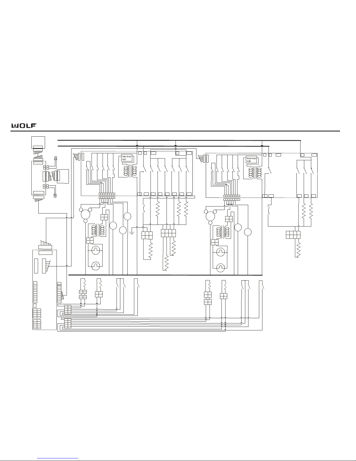
Wiring Diagrams
DDuuaall FFuueell RRaannggee
7-8
L1
L2
30" Oven
Relay
Board
K1
NO
K2NOK3
K4K5K6
NO
NO
NONO
K7
NO
K14
1
22
1
22
1234
5
6
78
9
1
234
1
3
Molex Sabr
e
Con
nector
Pizza
Element
Receptacle
Pizza El.
3
500W
2
40V
Outer
Bake
E
l
.
1000W
240V
Inner
Bake
E
l.
1200W
240V
Broil E l.
3600W
240V
R Cvt El.
24
00W
2
40V
L Cvt El
2400W
240V
Bi-meta l
T
hermos t at
(Thermo
Lim
iter)
1
4
2
Cooling
F
an
Motor
L
.Cvt
F
an
R. Cvt
F
a
n
M
otor
Doo
r
L
ock
20W Oven
Light
20
W Oven
Lig
ht
NEUT RAL
122
1
2
3
4
5
6
7
8
9
G
G
ND
12
Meat
Prob
e
Sensor
M
eat
Pro
be
Re
cepti cal
RT
D
Senso
r
12
M
o
lex
Con
nector
Amp
Co
nnector
M
DL
Un
latched
Switch
M
DL
L
atched
Switch
Doo
r
Switch
12
12
2 pi
n
Amp Conn.
2
pin
Amp
Con
n
112
2
123
4
L1
L1L2L1-B
L1-A
NEU DLB
Pr6
Pr5
Pr4 Pr3P
r2 P r1
J11A
J4
J1
NO
NO
NO
K9K10
K11
K12
K13
NONO
NO
NO
NO
NO
1234
5
6
78
9
J
3
2V L ED
Right
Mode/temp
knob
ECH
Assembl
y
12
12
110
110
110
110
Left
Mode/temp
knob
12
12
J1
J8
J7
J2
2V L ED
J6
1101
10
1101
10
1
2
3
4
5
6
8
9
7
1
9
1
9
1
2
3
4
5
6
8
9
10
J2
1
2
3
4
5
6
8
9
1
0
J
3
1
2
3
4
9
5
6
8
10
1
2
3
4
9
5
6
8
10
1
2
2
1
18" Oven
R
elay
Board
K1
N
O
K2
N
O
K3
N
O
K7
NO
K14
1
22
1
22
1
2
3
4
5
6
78
9
123
4
Molex Sabre
Con
nector
P
izza
Element
Receptacle
Inner
Bake
E
l.
1450W
240V
Bro
il E
l.
3
600W
240V
L Cvt
E
l
24
00W
24
0V
1
4
2
Co
oling
F
an
Motor
L.Cvt
F
a
n
Motor
Do
or
Lock
20W Oven
Light
20
W Oven
Lig
ht
1
2
Meat
Probe
Sensor
Meat
Pro
be
Re
cepti cal
RT
D
Sensor
12
Molex
Con
nector
Amp
Co
nnector
M
DL
Un
latched
Switch
MDL
L
atched
Switch
Doo
r
Switch
1
2
1
2
2 pi
n
Amp Conn.
2
pin
Amp
Co
nn
112
2
1
23
4
W olf Appliance
Company
, L LC
48" Dual Fu el Oven
Schematic Diagram
L1
L1 L2 L1-B
L1-A
NEU DLB
P
r3
P
r2 P
r1
J1
NO
NO
NO
K9
K10K11
K12K13
NO
NONO
NO
NO
NO
1
2
3
45
6
78
9
J3
1
2
2
1
122
J5
1
22
122
Oven
Control ler
Bi-metal
T
hermos tat
(
T
h
ermo Li miter)
Page 89
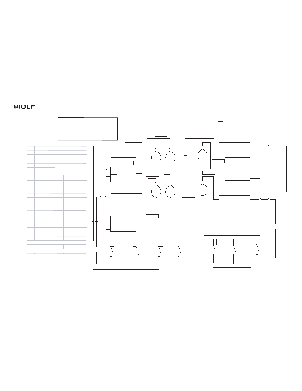
Wiring Diagrams
DDuuaall FFuueell RRaannggeess
7-9
CHARBROILER
SPARK
MODULE
L1
N
spark
lead
RIGHT
REAR
SPARK
MODULE
L1
N
spark
lead
RIGHT
FRONT
SPARK
MODULE
L1
N
spark
lead
POWER INPUT
AMP
CONNECTOR
N
3
L1
1
RIGHT
REAR
RIGHT
FRONT
CHAR-
BROILER
REAR
MIDDLE
SPARK
MODULE
L1
N
spark
lead
LEFT
REAR
SPARK
MODULE
L1
N
spark
l
ead
LEFT
F
RONT
SPARK
M
ODULE
L1
N
spa
rk
l
ead
F
RONT
MIDDLE
SPARK
MODULE
L1
N
spark
lead
MIDDLE
REAR
MIDDLE
FRONT
L
EFT
REAR
LEFT
F
RONT
RIGHT
FRONT
SWITCH
RIGHT
REAR
SWITCH
CHARBROILER
SWITCH
FRONT
M
IDDLE
SWITCH
REAR
MIDDLE
SWITCH
LEFT
FRONT
SWIT
CH
LEFT
REAR
SWITCH
1
9
10
11
16
17
18
6
2
3
5
7
12
15
21
4
8
20
19
14
13
Dual Fuel Rangetop Harness
Model DF486C
sparker wire
sparker wire
sparker wire
sparker wire
sparker wire
sparker wire
sparker wire
WIRE
WIRE CO LO R
INFO
1 BLACK L1 IN
2 W HITE N IN
3 WHIT E N JUMPER
4 BLACK/YELLOW SST RIGHT REAR
5 W HITE N JUMPER
6 BLACK/RED SST RIGHT FRONT
7WHITE N JUMPER
8BLACK/
GREEN SST
CHARBROILER
9BLACK L1 JUMP ER
10 BLACK L1 JUMPER
11 BLACK L1 JUMPER
12 WHITE
N JUMPER
13
BLACK/BLUE SST
MIDDLE F RO
NT
14
BLACK/PURPLE SST MIDDLE REAR
15 WHITE
N JUMPER
16 BLACK L1 JUMPER
17
BLACK L1 JUMPER
18 BLACK L1 JUMPER
19 BLACK/GRAY SST LEFT FRONT
20 BLACK/TAN SST LE F T REAR
21 WHITE
N JUMPER
SST: SINGLE STRIPE O
N THE WIRE
HA: HASH ON THE
WIRE
DST: DOUBLE S TRIPE ON THE WIRE
Page 90
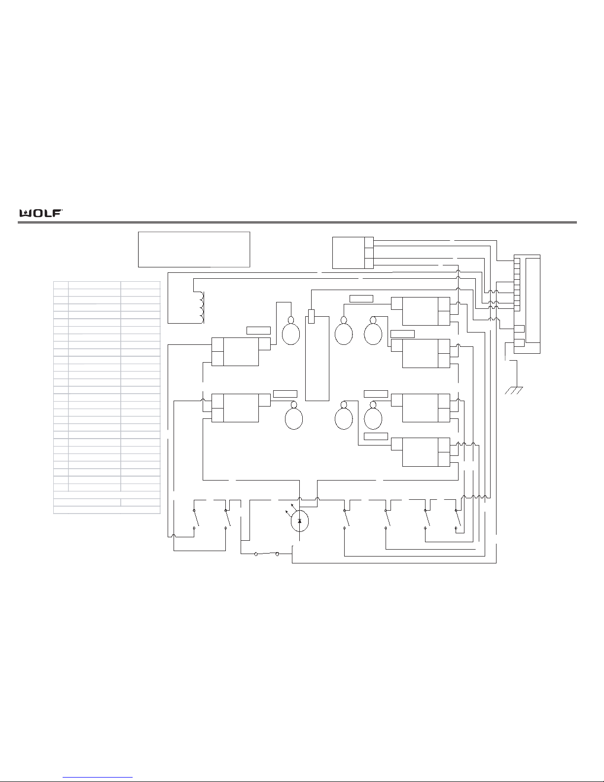
Wiring Diagrams
DDuuaall FFuueell RRaannggee
7-10
POWER INPUT
AMP
CONNECTOR
N
3
L1
1
10
J4
G
ND
9
8
7
6
5
4
3
2
1
DSI
S
P
A
R
K
E
R
MIDDLE
REAR
SPARK
MO
DULE
L1
N
spark
lead
RIGHT
R
EAR
SPARK
MODULE
L1
N
spark
lead
RIGHT
FRONT
SPARK
MO
DULE
L1
N
spark
lead
MIDDLE
FRONT
SPARK
MO
DULE
L1
N
spark
lead
MIDDLE
REAR
RIGHT
R
EAR
MIDDLE
FRONT
R
IGHT
FRONT
Griddle
LEFT
R
EAR
SPARK
MODULE
L1
N
spark
l
ead
LEFT
FRONT
S
PARK
MODULE
L1
N
spark
lead
LEFT
REAR
LEFT
FRONT
RIGHT
F
RONT
SWITCH
R
IGHT
REAR
SWITCH
MIDDLE
FRONT
SWITCH
MIDDLE
REAR
SWITCH
LEFT
FRONT
SWITCH
LEFT
R
EAR
SWITCH
t
o
THERMOSTAT
120 VAC
INDICATOR
LIGHT, LED
2
1
4
3
9
11
19
27
131415
20
23
17
25
8
22
6
7
5
12 10
16
18
24
26
Dual Fuel Rangetop Harness
Model DF486G
10VDC
GR
IDDLE/
FRENCH TOP
Solenoid
sparker wire
sparker wire
sparker wire
sparker wire
sparker wire
sparker wire
21
WIRE W IRE COLOR
INFO
1BLACK
L1 TO DSI
2BLAC
K
L1 IN
3 WHITE N TO DS I
4 WHITE N IN
5 GREEN/YELLOW DST SPARKER GND
6 WHITE/ORA NG E HA SOLENOID N
7 BLACK/ORANGE HA
SOLENOID
8 BLACK/ORANGE SST DSI INPUT
9 WHITE N JUM PER
10 BLACK/YELLOW SST RIGHT REAR
11 WHITE N JUMPER
12 BLACK/RED SST RIGHT FRONT
13BLACK L1 JUMPER
14BLACK
L1 JUMPER
15 BLACK L1 JUMPER
16 BLACK/BLUE SST MIDDLE FRONT
17 BLACK
L1 JUMPER
18 BLACK/PURPLE SST MIDDLE REAR
19 WHITE N JUMPER
20 WHITE N JUMPER
21 BLACK/ORANGE SST
LED INDICATOR
22 BLACK
L1 JUMPER
23 WHITE N JUMPER
24 BLACK/GRAY SST LEFT FRONT
25 BLACK
L1 JUMPER
26 BLACK/TAN SST LEFT REAR
27 WHITE N JUMPER
SST: SINGLE STRIPE ON THE WIRE
HA: HASH ON THE WIRE
DST: DOUBLE STRIPE O N THE WIRE
Page 91
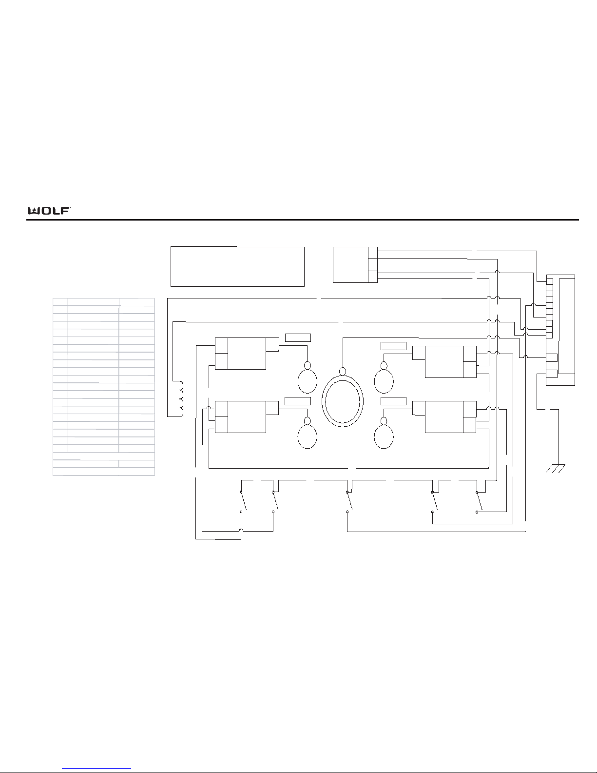
Wiring Diagrams
DDuuaall FFuueell RRaannggeess
7-11
POWER INPUT
AMP
CONNECTOR
N
3
L1
1
RIGHT
FRONT
SWITCH
RI
GHT
REAR
SWIT
CH
LEFT
F
RONT
SWITCH
LEFT
REAR
SWITCH
LEFT
REAR
RIGHT
FRONT
RIGHT
REAR
LEFT F
RONT
SPARK MODULE
L1
N
spark
lead
LEFT REAR
SPARK MODULE
L1
N
spark
lead
RIGHT REAR
SPARK MODULE
L1
N
spark
lead
RIGHT FRONT
SPARK MODULE
L1
N
spark
lead
4
9
19
2
13
12
10
18
17
16
sparker wire
sparker wire
sparker wire
sparker wire
Dual Fuel Rangetop Harness
Model DF484F
11
10
J4
GND
9
8
7
6
5
4
3
2
1
1
3
5
DSI
S
P
A
R
K
E
R
10
VDC
GRIDDLE/
F
RENCH TOP
Solenoid
6
7
FRENCHTOP
SWITCH
8
14
15
LEFT
FRONT
FRENCH
TOP
WIRE WIRE COLOR INF O
1BLACK L1 TO DSI
2BLACK L1 IN
3WHIT
E
N TO DSI
4 WHITE N IN
5 GREEN/YELL
OW DST
DSI GND
6
WHITE/ORANGE HA SOLENOID N
7BLACK/ORANGE HA
SOLENOID
8 BLACK/ORA NGE SST DSI INPUT
9 WHITE N JUM PER
10 BLACK/YELLOW SST RIGHT REAR
11 WHITE N JUMPER
12 BLACK/RED SST RIGHT FRONT
1
3BLACK L1 JUMP ER
14 BLACK
L
1 JUMPER
15 BLACK L1 JUMPER
1
6BLACK L1 JUMPER
17 BLACK/GRAY SST LEF T FRONT
18 BLACK/TAN SST LEFT REAR
19 WHITE N JUMPER
SST: SINGLE STRIPE ON THE WIRE
HA: HASH ON T
HE WIRE
DST: DOUBLE STRIPE ON THE WIRE
Page 92
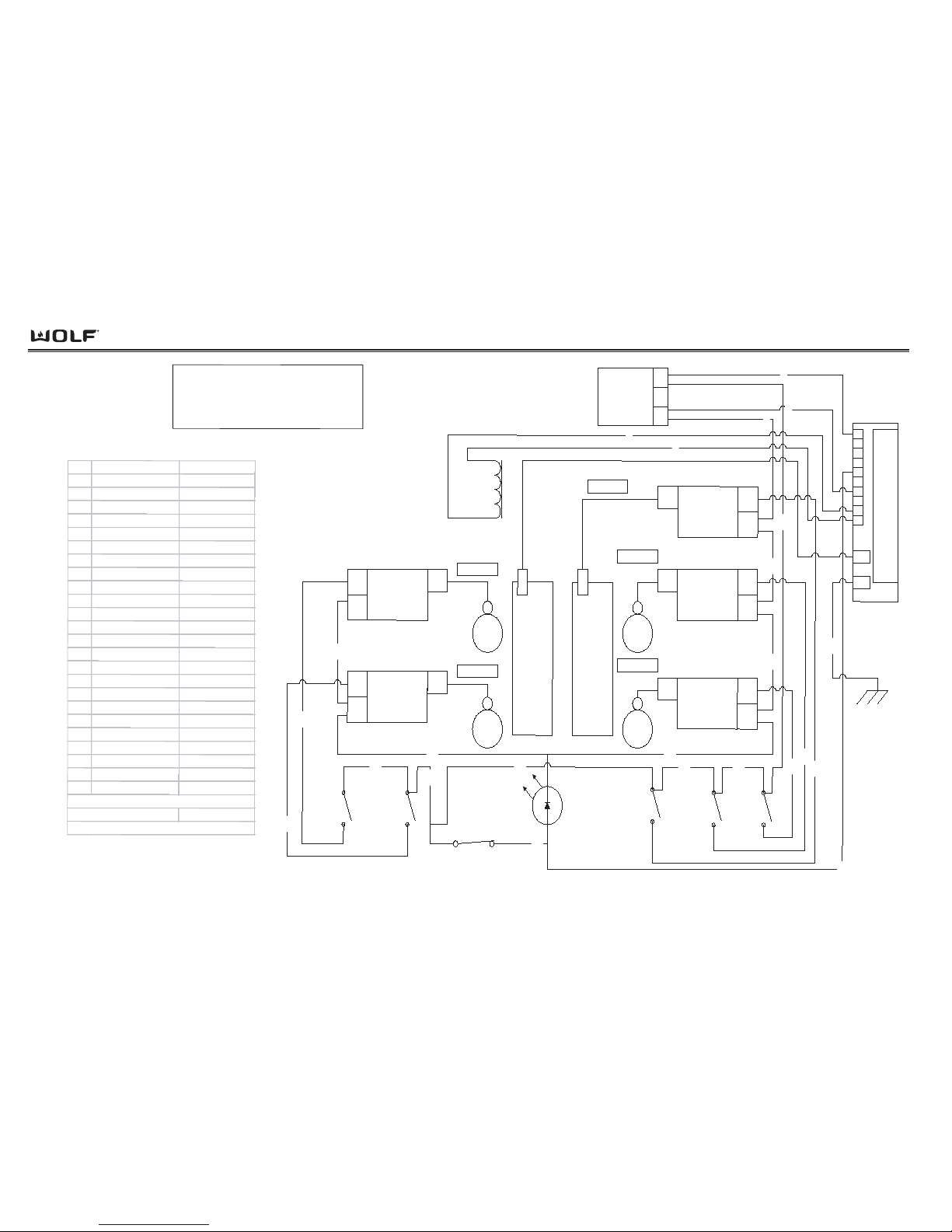
Wiring Diagrams
DDuuaall FFuueell RRaannggee
7-12
RIGHT
FRONT
SPARK
MODULE
L1
N
spark
lead
RIGHT
REAR
SPARK
MODULE
L1
N
spark
lead
10
J4
GND
9
8
7
6
5
4
3
2
1
DSI
S
P
A
R
K
E
R
RIGHT
REAR
RIGHT
FRONT
CHAR-
BROILER
CHARBROILER
SPARK
MODULE
L1
N
spark
lead
Griddle
LEFT
R
EAR
SPARK
MODULE
L1
N
spark
lead
LEFT
FRONT
SPARK
MODULE
L1
N
spark
lead
POWER INPUT
AMP
CONNECTOR
N
3
L1
1
LEFT
FRONT
LEFT
REAR
120
VAC
INDICATOR
LIGHT, LED
t
o
THERMOSTAT
RIGHT
FRONT
SWITCH
RIGHT
REAR
SWITCH
CH
ARBROILER
SWITCH
LEFT
FRONT
SWITCH
LEFT
REAR
SWITCH
1
2
3
4
9
11
17
19
13
14
15
18
21
20
8
12
10
16
22
24
23
1
0VDC
GRIDDLE/
FRENCH TOP
Solenoid
5
7
6
Dual Fuel Rangetop Harness
Model DF484CG
sparker wire
sparker wire
sparker wire
sparker wire
sparker wire
WIRE
WIRE CO LO R
INFO
1BLACK
L1 TO DSI
2
BLACK
L1 IN
3
WHITE
N TO DSI
4
WHITE
N IN
5
GREEN/YELLOW DST
SPARKER GND
6
WHITE/ORANGE HA
SOLENOID N
7
BLACK/ORANGE HA
SOLENOID
8
BLACK/ORANGE SST
DSI IN PUT
9WHITE
N JUMPER
10
BLACK/YELLOW SST
RIGHT REAR
11 WHITE
N JUMPER
12 BLACK/RED SST
RIGHT FRONT
13 BLACK
L1 JUMPER
14
BLACK
L1 JUMPER
15 BLACK
L1 JUMPER
16 BLACK/GREEN SST
CHARBROILER
17 WHITE
N JUMPER
18 BLACK
L1 JUMPER
19 WHITE
N JUMPER
20
BLACK/ORANGE SST
LED INDICATOR
21 BLACK
L1 JUMPER
22 BLACK/GRAY SST
LEFT FRONT
23 WHITE
N JUMPER
24 BLACK/TAN SST
LEFT REAR
SST: SINGLE STRIPE ON THE WIRE
HA: HASH ON THE WIRE
DST: DOUBLE S TRIPE ON THE WIRE
Page 93
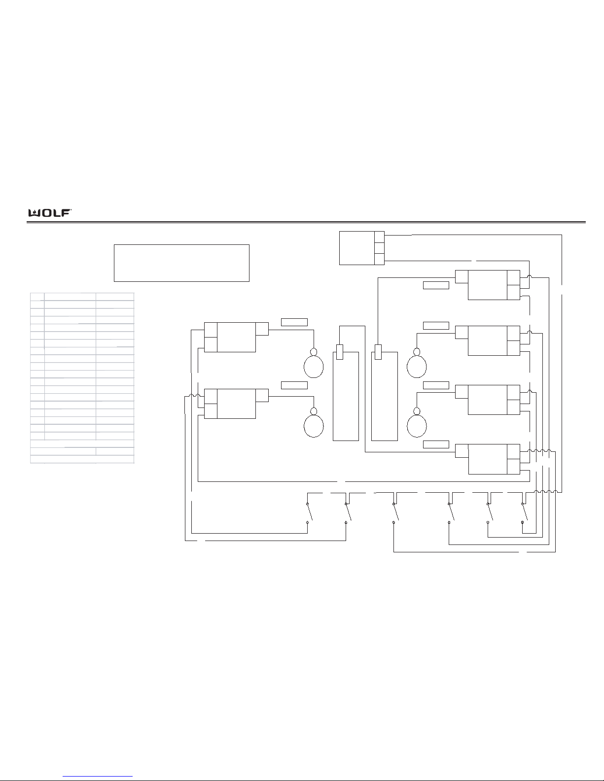
Wiring Diagrams
DDuuaall FFuueell RRaannggeess
7-13
RIGHT
CHARBROILER
SPARK
MODULE
L1
N
spark
lead
RIGHT
REAR
SPARK
MODULE
L1
N
spark
lead
RIGHT
FRON
T
SPARK
M
ODU
LE
L1
N
spark
lead
LEFT
CHARBROILER
SPARK
MODULE
L1
N
spark
lead
RIGHT
REAR
RIGHT
F
RON
T
CHAR-
BROILER
CHAR-
BROI
LER
LEFT
REAR
S
PARK
MODULE
L1
N
spark
lead
LEFT
FR
ONT
SPARK
MODU
LE
L1
N
spark
lead
LEFT
REAR
LEFT
FRONT
POWER INPUT
AMP
CONNECTOR
N
3
L1
1
RIGHT
FRONT
SWITCH
R
IGHT
REAR
SWITCH
R
IGHT
CHARBROILER
SWIT
CH
LEFT
C
HARBROILER
SWITCH
LEFT
FRON
T
SWITCH
LEFT
REAR
SWITCH
1
2
3
5
7
17
9
10
11
12
15
18
6
4
8
13
16
14
Dual Fuel Rangetop Harness
Model DF48DC
sparker wire
sparker wire
sparker wire
sparker wire
sparker wire
sp
arker w
ire
WIRE
WIRE CO LO R
INFO
1BLACK
L1 IN
2WHITE
N IN
3WHITE
N JUMPER
4 BLACK/YELLOW SST
RIGHT REAR
5WHITE
N JUMPER
6
BLACK/RED SST
RIGHT FRONT
7
WHITE
N JUMPER
8
BLACK/GREEN SST
CHARBROILER
9BLACK
L1 JUMPER
10 BLACK
L1 JUMPER
11 BLACK
L1 JUMPER
12
BLACK
L1 JUMPER
1
3
BLACK/ORANGE SST
CHARBROILER
14
BLACK/GRAY SST
LEFT FRONT
1
5
BLACK
L1 JUMPER
16 BLACK/TAN SST
LEFT REAR
17 W
HITE
N JUMPER
18 WHITE
N JUMPER
SST: SINGLE STRIPE ON THE WIRE
HA: HASH ON THE WIRE
DST: DOUBLE STRIPE ON THE WIRE
Page 94
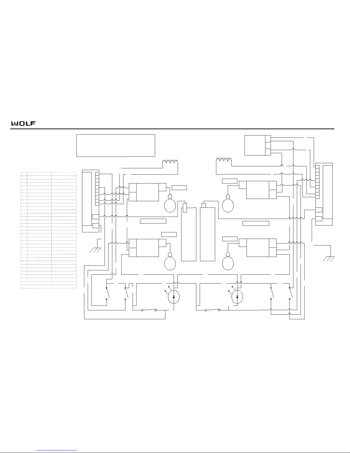
Wiring Diagrams
DDuuaall FFuueell RRaannggee
7-14
RIGHT
REAR
SPARK
MODULE
L1
N
spark
lead
RIGHT
FRONT
SPARK
MODULE
L1
N
spark
lead
POWER INPUT
AMP
CONNECTOR
N
3
L1
1
10
J4
GND
9
8
7
6
5
4
3
2
1
DSI
S
P
A
R
K
E
R
10
J4
GND
9
8
7
6
5
4
3
2
1
DSI
S
P
A
R
K
E
R
LEFT
REAR
SPARK
M
ODULE
L1
N
spark
lead
LEFT
FRONT
SPARK
MODULE
L1
N
spark
lead
Griddle
LEFT
REAR
LEFT
FRONT
RIGHT
REAR
RIGHT
FRONT
10VDC
Single Solenoid
1
3
4
9
5
7
8
27
120 VAC
INDI
CATOR
LIGHT, LED
t
o
TH
ERMOSTAT
18
120 VAC
INDICATOR
LIGHT, LED
t
o
THERMOSTAT
17
R
IGHT
FRONT
SWITCH
RIGHT
REAR
SWITCH
LEFT
FRONT
SWIT
CH
LEFT
REAR
S
WITCH
2
11
16
26
13
14
15
20
22
6
19
23
25
29
28
12
10
24
Dual Fuel Rangetop Harness
Model DF48DG
sparker wire
sparker wire
sparker wire
sparker w
ire
Griddle
30
WIRE W IRE COLOR
INFO
1BLACK
L1 INTO DSI (1)
2BLACK
L1 IN
3WHITE
N INTO DSI (1)
4WHITE
N IN
5 GREEN/YELLOW DST
SPARKER GND (1
)
6 BLACK/ ORANGE SST
DSI INPUT
(1)
7WHITE/
ORANGE H
A
SOLENO ID N (
1)
8 BLACK/ ORANGE HA
SOLENOID (1)
9
W
HITE
N JUMPER
1
0 BLACK/ YELLOW
SS
T
RIGHT REAR
11
WHITE
N
J
UMPER
12
BLACK/
RED S
ST
FRONT R
EAR
13
BLACK
L1 JUMPER
14 BLACK
L
1 JUMPER
1
5BLACK
L1
JUMPER
16
WHITE
N
J
UMPER
17
BLACK/ ORANGE SST LED INDICATOR (1)
1
8
BLACK/ GREEN SST LED INDICAT
OR (2)
19
BLACK/
GREEN SST DSI INPUT
(2)
20 BLACK
L1 JUMPER
21 WHITE
N JUMPER
22
BLACK
L1
JUMPER
23 BLACK/ GRAY SST
LEFT FRONT
24
BLACK L1 INTO DSI (2)
25 BLACK/
TAN SST
LEFT R
EAR
26 WHITE
N JUMPER
27
WHITE N INTO
DSI
(2)
28
WHITE/ GR
EEN HA S OL E NO ID N (2
)
29
BLACK/
GREEN H
A SOLENOID (2)
30
GRE
EN/ YEL
LOW DST S
PARKER
GND (2)
SST: SINGLE STRIPE ON THE WIRE
H
A:
HA
SH O
N THE WIRE
DST:
DOUBLE STRIPE ON
THE WIRE
10VDC
Single Solenoid
sparker electrode wire
sparker electrode wire
Page 95
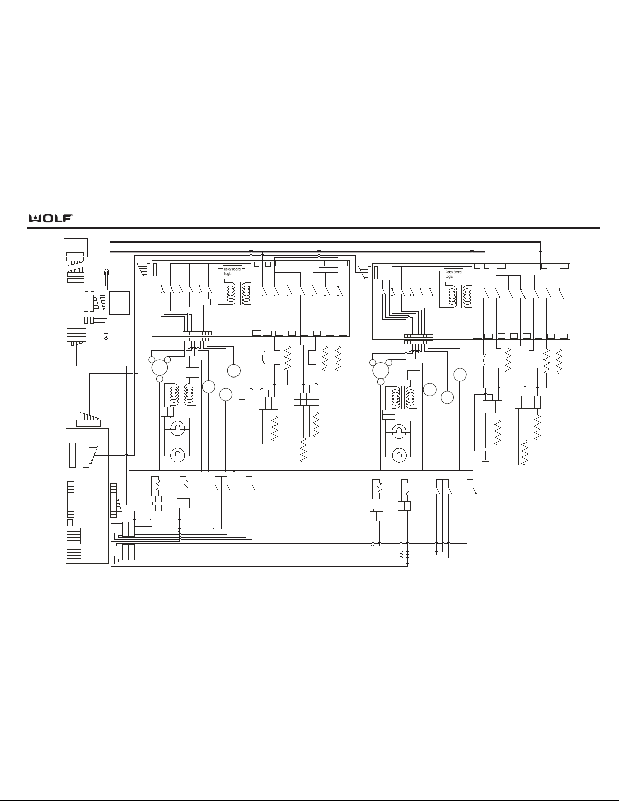
Wiring Diagrams
DDuuaall FFuueell RRaannggeess
7-15
L1
L2
30" R ight
Relay
Board
K1NOK2NOK3K4K5K6
NO
NO
NONOK7NO
K14
1
22
1
22
12345678
9
1234
13
Molex S abre
Connector
Pizza
El ement
Re ceptacle
Pizza El.
3500W
240V
Outer Bak e El.
1000W
240V
Inner B ake El.
1200W
240V
Broil El.
3600W
240V
R Cvt El.
2400W
240V
L Cvt El
2400W
240V
Bi-metal
Thermostat
(Thermo
Limiter)
1
4
2
Cooling
Fan Motor
L.Cvt
Fan
R. Cvt
Fan
Motor
Door
Lock
20W Oven
Light
20W Oven
Light
NEUT RAL
122
1
2
3
4
5
6
7
8
9
G
GND
12
Meat
Probe
Sensor
Meat
Probe
Re ceptical
RTD
Sensor
12
Molex
Connector
Amp
Connector
MDL
Unlatched
Switch
MDL
Latched
Switch
Door
Switch
12
12
2 pin
Amp Conn.
2 pin
Amp
Conn
112
2
1234
L1
L2
L1-B L1-A
DLB
Pr6
Pr5 Pr4 Pr3 Pr2 Pr1
J11A
J4
J1
NO NO NO
K9K10K11
K12
K13
NONONONONO
NO
123456789
J3
2V L ED
Right
Mode/temp
knob
ECH
Assembly
12
12
110
110
110
110
Left
Mode/temp
knob
12
12
J1
J8
J7
J2
2V L ED
J6
110
110
110
110
1
2
3
4
5
6
8
9
7
19
19
1
2
3
4
5
6
8
9
10
J2
1
2
3
4
5
6
8
9
10
J3
1
2
3
4
9
5
6
8
10
1
2
3
4
9
5
6
8
10
12
2
1
Relay
Board
K1NOK2NOK3
NO
K7
NO
K14
1
22
1
22
12345678
9
1234
Molex S abre
Connector
Inner B ake El.
1450W
240V
Broil El.
3600W
240V
L Cvt El
2400W
240V
1
4
2
Cooling
Fan Motor
L.Cvt
Fan
Motor
Door
Lock
20W Oven
Light
20W Oven
Light
12
Meat
Probe
Sensor
Meat
Probe
Re ceptical
RTD
Sensor
12
Molex
Connector
Amp
Connector
MDL
Unlatched
Switch
MDL
Latched
Switch
Door
Switch
12
12
2 pin
Amp Conn.
2 pin
Amp
Conn
112
2
1234
W olf Appliance
Company , L L C
60" Dual Fu el Oven
Schematic Diagram
L1L1 L2 L1-B L1-A
NEU DLB P r3 Pr 2 P r1
J1
NO NO NO
K9K10K11K12K13
NONONONONO
NO
123456789
J3
12
2
1
122
J5
122
122
Oven
Control ler
Bi-metal
Thermostat
R. Cvt
Fan
Outer Bak e El.
1000W
240V
13
Pizza
El ement
3500W
240V
G
Re ceptacle
Pr6 Pr5 Pr4
K4K5K6
NONONO
R Cvt El
2400W
240V
NEU
L1
Oven
Oven
30" L eft
GND
Page 96
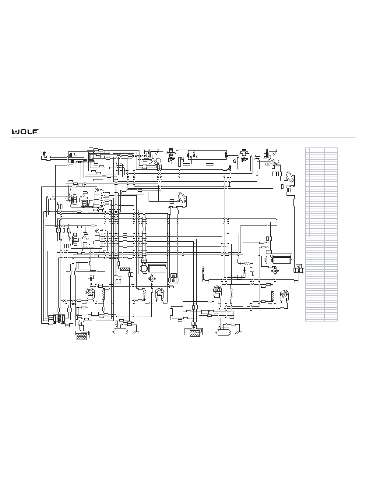
Wiring Diagrams
DDuuaall FFuueell RRaannggee
7-16
Wolf Appliance Company, LLC
60" W iring Diagram
W ol f # 805289A R evison A
MODE LS : DF 606CG, DF606CG-L P , DF604CF ,
DF 604CF-L P, DF 604GF, D F604GF -LP , DF 606DC,
DF 606DC-LP , DF 606DG, DF 606DG-L P, DF 606F,
DF 606F-L P
L2 Splice
Right Convection
Element
Broil Element
Left Convection
Element
234
321
1
Pizza
El ement
Recept acle
1122
Terminal
Block
LOHI
AMP
CONNECTOR
Mates with
Rangetop
1
3
L2 splice
1122
L
ig
h
t
Trans
fo
rm
e
r
11
11
2
22
2
L
i
g
h
t
Tran
s
fo
rmer
11
11
2
22
2
Relay Board
1
12
2
Unlatched
Switch
Latched
Switch
Door
Switch
Motor Door
Lock
234
321
1
Cooling Fan
11223
3
1
12
2
UnlatchedS witch
Latched
Switch
Door
Switch
Motor Door
Lock
neutral splice
Relay Board
NL2L1
ECH Assembly (Pod)
LOHI
Oven Controller
Board
1
6
1
6
Cooling Fan
11223
3
75
2
1
3
4
5
61
62
63
64
65
70
69
68
66
10
9
8
6
OC to Pod
67
7
15
14
30
21
19
22
23
20
18
13
67
53
717374
77
72
8480
79
82
81
39
41
18
48 49
36
37
43
44
45
46
47
26
27
42
47
51
24
50
fuse
fuse
28
40
49 17
36
37
34
35
91
90
91
90
56
57
11
20
31
33
32
113113
38
51
40
55
56
57
29
28
26
27
25
24
29
32
14
5
4
3
10
9
33
15
16
61
62
66
69
63
76
85
71
73
55
82
68
70
88
89
74
87
65
64
89
88
35
34
22
42
8
6
79
53
19
30
83
41
218139
483880
83
12
17
25
OC to Pod
Pod to Knob
Pod to Knob
2V LED 2V LED
Manual Reset
Bi-metal Thermostat
(Thermo - Limiter)
Manual Reset
Bi-metal Thermostat
(Thermo - Limiter)
Left
Convection
Fan
Right
Convection
Fan
RTD
Bake
Element
Right
Oven
Light
Meat Probe
Receptacle
Temperature
Knob and
Selector Switch
Temperature Knob and
Selector Switch
Right
Oven
Light
RTD
Broil Element
Left Convection
Element
Left
Oven
Light
75
84
Meat Probe
Receptacle
Pizza
Element
Recept acle
78
85
WIRE WIRE COLOR INFO
1GRAY MP
2 GRAY/BLACK DST MP3 BROWN/BLACK DS T MN
4BROWN MU
5 PURPLE MDL
6TAN RTD
7 BLACK RB TO OC 22 wires
8 TAN/BLACK DST RTD-
9 YELLOW DS
10YELLOW/BLACK DST DS11BLACK/WHITE DST HF
12BLACK RB JUMPER
13 LT BLUE LF
14BLACK/WHITE HA TRANS
15 GRAY/BLACK HA MDL
16 PURPLE/BLACK HA MN JUMPER
17 ORANGE LCF
18 BLUE RCF
19 BLACK L1 LOGIC
20 WHITE N LOGIC
21 RED L2
22 RED DLB TO TCO
23 BLACK L1 JUMPER
24BLACK/PURPLE DST PIZZA
25BLACK/BLUE DST RCE
26BLACK/GREEN DST O BAKE
27BLACK/YELLOW DST I BAKE
28BLACK/ORANGE DST LCE
29 BLACK/RED DST BROIL
30 BLACK L1 RELAYS
31W HITE NEUTRAL
32W HITE NEUTRAL
33W HITE NEUTRAL
34 RED TRANS TO LIGHT
35BLUE TRANS TO LIGHT
36 RED LIGHT TO LIGHT
37 BLUE LIGHT TO LIGHT 2
38 WHITE COOL FAN N
39RED RANGE TOP L2
40 RED L2
41W HITE RANGETOP N
42 RED TCO TO SPLICE L2
43 RED L2
44 RED L2
45 RED L2
46 RED L2
47 RED L2
48 WHITE RCF N
49 WHITE LCF N
50 GREEN PIZZA GND
51 RED BROIL L2
52GREEN PIZZA GND
53BLACK L1 RELAYS
54BLACK L1 JUMPER
55BLACK/RED HA BROIL
56BLACK/ORANGE HA LCE
57BLACK/YELLOW HA I BAKE
58BLACK/GREEN HA O BAKE
59 BLACK/BLUE HA RCE
60BLACK/PURPLE HA PIZZA
61TAN/BLACK HA MP
62TAN/BLACK SST MP63BROWN/BLACK SST MN
64BROWN/BLACK HA MU
65 PURPLE/BLACK HA ML
66TAN/BLACK HA RTD
67 WHITE RB TO OC
68YELLOW HA DS
69TAN/BLACK SST RTD70YELLOW SST DS71BROWN/GRAY DST LF
72BLACK RB JUMPER
73 LT BLUE/BLACK DST HF
74BLACK/GRAY DST TRANS
75BLACK/GRAY HA MDL
76PURPLE/BLACK SST MN JUMPER
77 ORANGE/BLACK HA LCF
78 BLUE/BLACK S ST RCF
79 BLACK L1 LOGIC
80 WHITE N LOGIC
81 RED L2
82 RED DLB TO TCO
83 WHITE COOL FAN N
84 WHITE MDL N
85 WHITE RCF N
86 RED L2
87 WHITE TRANS N
88BLUE TRANS TO LIGHT
89 RED TRANS TO LIGHT
90 BLUE LIGHT TO LIGHT
91 RED LIGHT TO LIGHT 2
92 RED L2
93 RED L2
94 WHITE CVF TO CVF N
95 RED L2
96 RED L2
97 RED L2
98 RED L2
99 RED L2
Right Convection
Element
Right
Convection
Fan
58
L2 splice
L2 Splice
52
99
77
94
85
94
98
97
95
93
92
78
96
86
86
96
58
59
60
54
98
99
59
Left
Convection
Fan
Left
Oven
Light
Bake
Element
Page 97
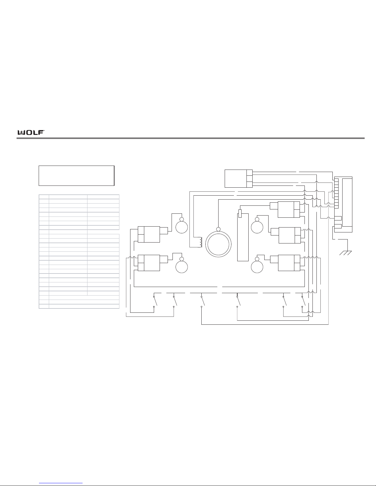
Wiring Diagrams
DDuuaall FFuueell RRaannggeess
7-17
8
POWER INPUT
AMP
CONNECTOR
N
L1
10
J4
GND
9
8
7
6
5
4
3
2
1
DSI
S
P
A
R
K
E
R
RIGHT
REAR
RIGHT
FRONT
Char-
Broiler
LEFT
REAR
LEFT
FRONT
RIGHT
FRONT
SWITCH
RIGHT
REAR
SWITCH
LEFT
FRONT
SWITCH
LEFT
REAR
SWITCH
2
1
3
19
6
7
5
10VDC
FRENCH
TOP
Solenoid
RIGHT
REAR
SPARK
MODULE
L1
N
spark
lead
RIGHT
FRONT
SPARK
MODULE
L1
N
spark
lead
LEFT
REAR
SPARK
MODULE
L1
N
spark
lead
LEFT
FRONT
SPARK
MODULE
L1
N
spark
lead
12
10
4
11
131415
17
22
20
21
CHAR-
BROILER
SPARK
MODULE
L1
N
spark
lead
9
CHAR-
BROILER
SWITCH
16
WIRE W IRE CO LO R INFO
1 B L A CK L1 TO DS I M ODUL E
2BLACK L1 IN
3 WHITE N TO DSI MO DULE
4 WHITE N IN
5 GREEN/YELLOW DST SPARKER GND
6 WHITE/ORANG E HA SOL ENOID N
7 B L A CK/ORANG E HA S O LENOID
8 B L A CK/ORANG E SST DSI GRIDDLE INP UT
9 WHITE N JUMP ER
10 BLACK/YELLOW SST RIGHT REAR
11 W HITE N JUMPER
12 BLACK/RED SST RIGHT FRONT
13 BLACK L1 JUMPER
14 BLACK L1 JUMPER
15 BLACK L1 JUMPER
16 BLACK/GREEN SST CHARBROILER
17 W HITE N JUMPER
18 BLACK L1 JUMPER
19 BLACK L1 JUMPER
20 BLACK/GRAY SST LEFT FRONT
21 BLACK/TAN SST LEFT REAR
22 W HITE N JUMPER
NOTE SST: SINGLE STRIPE ON THE WIRE
HA:HASH MA RKING On THE WIRE
DST: DOUB L E STRIPE ON THE WIRE
FRENCH
TOP
18
FRENCH TOP
SWITCH
Dual Fuel Rangetop Harness
Model DF604CF
Page 98
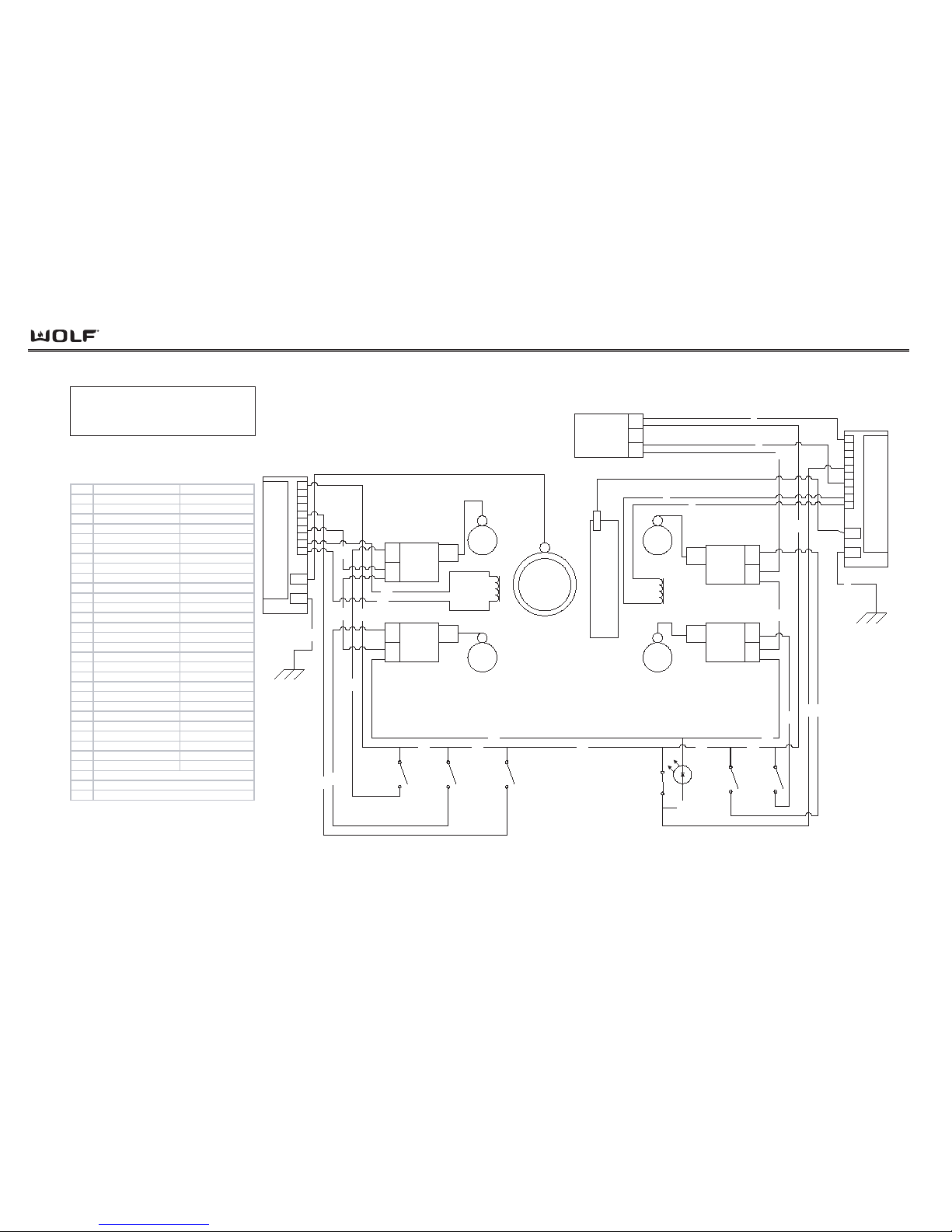
Wiring Diagrams
DDuuaall FFuueell RRaannggee
7-18
POWER INPUT
AMP
CONNECTOR
N
L1
10
J4
GND
9
8
7
6
5
4
3
2
1
DSI
S
P
A
R
K
E
R
RIGHT
REAR
RIGHT
FRONT
Griddle
LEFT
REAR
LEFT
FRONT
RIGHT
FRONT
SWITCH
RIGHT
REAR
SWITCH
FRENCH TOP
SWITCH
LEFT
FRONT
SWITCH
LEFT
REAR
SWITCH
t
o
GRIDDLE
THERMOSTAT
120 VAC
INDICATOR
LIGHT, LED
2
1
3
8
19
6
7
5
10VDC
FRENCH
TOP
Solenoid
10VDC
Right
GRIDDLE
Solenoid
10
J4
GND
9
8
7
6
5
4
3
2
1
DSI
S
P
A
R
K
E
R
RIGHT
REAR
SPARK
MODULE
L1
N
spark
lead
RIGHT
FRONT
SPARK
MODULE
L1
N
spark
lead
LEFT
REAR
SPARK
MODULE
L1
N
spark
lead
LEFT
FRONT
SPARK
MODULE
L1
N
spark
lead
12
10
4
9
11
20
1318
21
14
27
16
17
23
24
25
26
22
28
FRENCH
TOP
WIRE WIRE COL OR INFO
1 BLACK L1 TO DSI (1)
2 BLACK L1 IN
3 WHITE N TO DSI (1)
4 WHITE N IN
5 GREEN/YELLOW DST SPARKER GND (1)
6 WHITE/ORANGE HA SOLE NO ID N (1)
7 BLA CK/ORANGE HA S O LENOID (1)
8 BLA CK/ORANGE SST DSI GRIDDLE (1)
9 WHITE N JUMPE R
10 BLACK/YELLOW SST RIGHT REAR
11 WHITE N JUMPER
12 BLACK/RED SST RIGHT FRONT
13 BLACK L1 JUMPER
14 BLACK L1 JUMPER
15 BLACK L1 JUMPER
16 BLACK/GREEN SST FRENCH TOP
17 WHITE N JUMPER
18 BLACK L1 JUMPER
19 BLACK L1 JUMPER
20 BLACK/ORANGE SST LED INDICATOR
21 BLACK L1 JUMPER
22 BLACK/GRAY SST LEFT REAR
23 WHITE N JUMPER
24 WHITE N TO DSI (2)
25 WHITE/GREEN HA L1 JUMPER
26 BLACK/GREEN HA LEFT FRONT
27 GREEN/YELLOW DST SPARKER GND
28 BLACK/TAN SST LEFT REAR
NOTE SST: SINGLE STRIPE ON THE WIRE
HA: HASH MARK ING ON THE WIRE
DST: DOUB LE STRIPE ON THE WIRE
15
Dual Fuel Rangetop Harness
Model DF604GF
Page 99
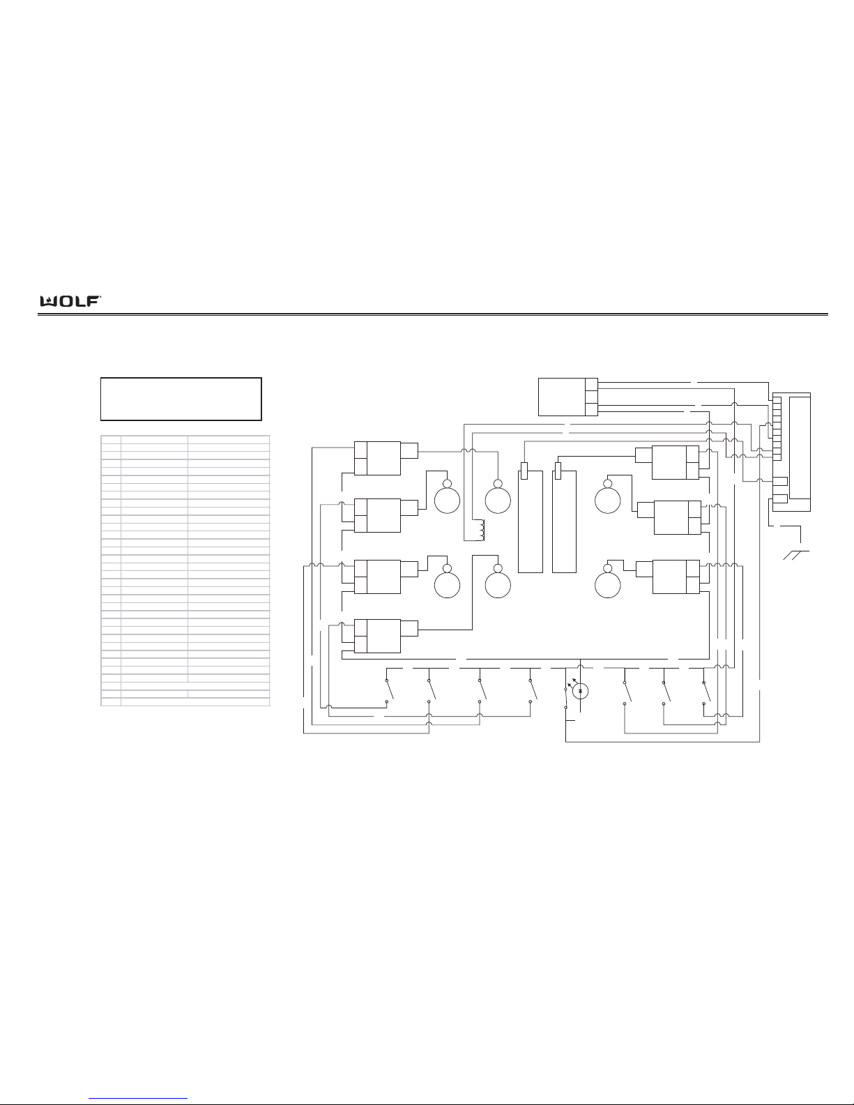
Wiring Diagrams
DDuuaall FFuueell RRaannggeess
7-19
POWER INPUT
AMP
CONNECTOR
N
L1
10
J4
GND
9
8
7
6
5
4
3
2
1
DSI
MIDDLE
REAR
RIGHT
REAR
MIDDLE
FRONT
RIGHT
FRONT
CharBroiler
LEFT
REAR
LEFT
FRONT
RIGHT
FRONT
SWITCH
RIGHT
REAR
SWITCH
MIDDLE
FRONT
SWITCH
MIDDLE
REAR
SWITCH
LEFT
FRONT
SWITCH
LEFT
REAR
SWITCH
2
1
3
25
6
7
5
10VDC
Left
Griddle
Solenoid
120 VAC
INDICATOR
LIGHT, LED
Griddle
MIDDLE
REAR
SPARK
MODULE
L1
N
spark
lead
RIGHT
REAR
SPARK
MODULE
L1
N
spark
lead
RIGHT
FRONT
SPARK
MODULE
L1
N
spark
lead
LEFT
REAR
SPARK
MODULE
L1
N
spark
lead
LEFT
FRONT
SPARK
MODULE
L1
N
spark
lead
MIDDLE
FRONT
SPARK
MODULE
L1
N
spark
lead
12
10
4
11
17
132123 18
t
o
LEFT
THERMOSTAT
1415
20
19
28
29
30
22
26
27
24
WIRE WIRE COL OR INF O
1 BLACK L1 TO DSI M O DULE
2BLACK L1 IN
3 WHITE N TO DS I M O DULE
4 WHITE N IN
5 GREEN/YELLOW DST SPARKER GND
6 WHITE/O RANGE HA SO LENOID COMMON
7 BLACK /ORANGE HA SOLE NO ID
8 BLACK /ORANGE S ST DSI GRIDDLE INPUT
9 WHITE N JUM PER
10 BLACK/YELLOW SST RIGHT REAR BURNER
11 WHITE N JUMPER
12 BLACK/RED SST RIGHT FRONT BURNER
13 BLACK L1 JUMPER
14 BLACK L1 JUMPER
15 BLACK L1 JUMPER
16 BLACK/GREEN SST CHARBROILER
17 WHITE N JUMPER
18 BLACK L1 JUMPER
19 WHITE N JUMPER
20 BLACK/ORANGE SST LED INDICATOR
21 BLACK L1 JUMPER
22 BLACK/BLUE SST MIDDLE FRONT BURNER
23 BLACK L1 JUMPER
24 BLACK/PURPLE SST MIDDLE REAR BURNER
25 BLACK L1 JUMPER
26 BLACK/GRAY SST LEFT FRO NT BURNER
27 BLACK/TAN SST LEF T REAR BURNER
28 WHITE N JUMPER
29 WHITE N JUMPER
30 WHITE N JUMPER
NOTE SST: SINGLE STRIPE THE WIRE
HA: HASH THE WIRE
DST: DOUBL E STRIPE THE WIRE
CHAR-
BROILER
SPARK
MODULE
L1
N
spark
lead
9
CHAR-
BROILER
SWITCH
16
8
Dual Fuel Rangetop Harness
Model DF606CG
S
P
A
R
K
E
R
Page 100
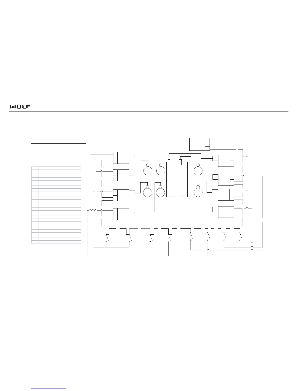
Wiring Diagrams
DDuuaall FFuueell RRaannggee
7-20
POWER INPUT
AMP
CONNECTOR
N
L1
RIGHT
REAR
RIGHT
FRONT
CHAR-
BROILER
MIDDLE
REAR
MIDDLE
FRONT
LEFT
REAR
LEFT
FRONT
RIGHT
FRONT
SWITCH
RIGHT
REAR
SWITCH
RIGHT
CHARBROILER
SWITCH
FRONT
MIDDLE
SWITCH
REAR
MIDDLE
SWITCH
LEFT
FRONT
SWITCH
LEFT
REAR
SWITCH
1
111213151719
8
2
3
5
9
22
23
24
6
4
21
20
18
16
Dual Fuel Rangetop Harness
Model DF606DC
WIRE WIRE COLOR INFO
1BLACK L1 IN
2 W HITE N IN
3 W HITE N JUMPER
4 BLACK/G REEN SST R. CHARBROILER
5 W HITE N JUMPER
6 BLACK/YELLOW SST RIGHT REAR
7 W HITE N JUMPER
8 BLACK/RED SST RIGHT FRONT
9 W HITE N JUMPER
10 BLACK/ORANGE SST L. CHARBROILER
11 BLACK L1 JUMPER
12 BLACK L1 JUMPER
13 BLACK L1 JUMPER
14 BLACK L1 JUMPER
15 BLACK L1 JUMPER
16 BLACK/BLUE SST MIDDLE FRONT
17 BLACK L1 JUMPER
18 BLACK/PURPLE SST MIDDLE REAR
19 BLACK L1 JUMPER
20 BLACK/GRAY SST LEFT FRONT
21 BLACK/TAN SST LEFT REAR
22 WHITE N JUMPER
23 WHITE N JUMPER
24 WHITE N JUMPER
NOTE: SST: SINGLE STRIPE THE WIRE
HA: HASH ON THE WIRE
DST: DOUBL E STRIPE THE WIRE
CHAR-
BROILER
LEFT
CHARBROILER
SWITCH
10
7
14
FRONT
MIDDLE
SPARK
MODULE
L1
N
spark
lead
LEFT
FRONT
SPARK
MODULE
L1
N
spark
lead
LEFT
REAR
SPARK
MODULE
L1
N
spark
lead
REAR
MIDDLE
SPARK
MODULE
L1
N
spark
lead
RIGHT
CHAR-
BROILER
SPARK
MODULE
L1
N
spark
lead
RIGHT
FRONT
SPARK
MODULE
L1
N
spark
lead
RIGHT
REAR
SPARK
MODULE
L1
N
spark
lead
LEFT
CHAR-
BROILER
SPARK
MODULE
L1
N
spark
lead
 Loading...