

Page 1
DOWNDRAFT VENTILATION
INSTALLATION GUIDE
SPECIFICATIONS, INSTALLATION, AND MORE
Page 2

DOWNDRAFT VENTILATION
Contents
3 Downdraft Ventilation
4 Specications
9 Installation
14 Troubleshooting
Features and specications are subject to change at any
time without notice. Visit wolfappliance.com/specs for the
most up-to-date information.
Important Note
To ensure this product is installed and operated as safely
and efciently as possible, take note of the following types
of highlighted information throughout this guide:
IMPORTANT NOTE highlights information that is especially
important.
CAUTION indicates a situation where minor injury or product
damage may occur if instructions are not followed.
WARNING states a hazard that may cause serious injury or
death if precautions are not followed.
IMPORTANT NOTE: Throughout this guide, dimensions in
parentheses are millimeters unless otherwise specied.
IMPORTANT NOTE: Save these instructions for the local
electrical inspector.
2 | Wolf Customer Care 800.222.7820
Page 3
DOWNDRAFT VENTILATION
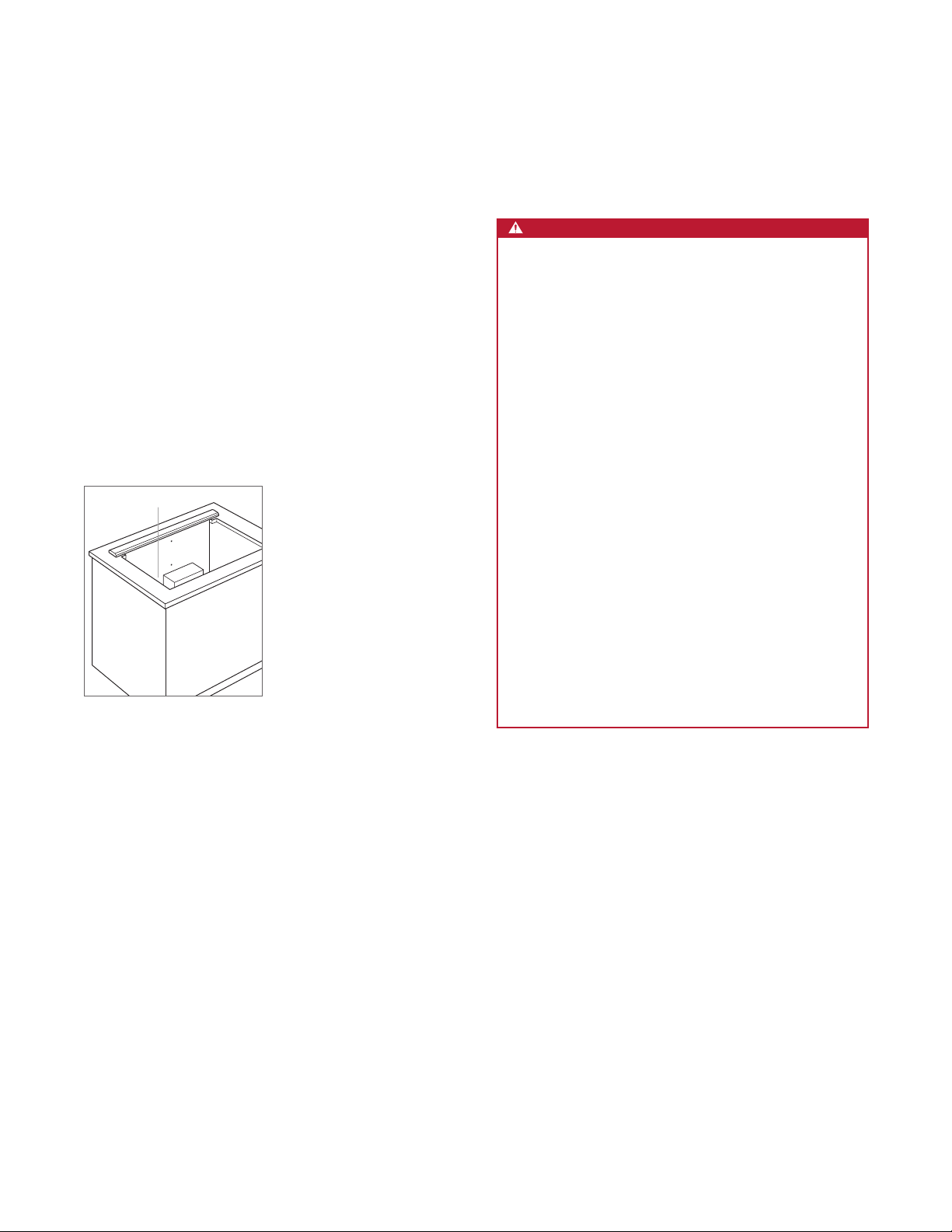
Product Information
Important product information, including the model and
serial number, are listed on the product rating plate. The
rating plate is located next to the blower housing on the
front side of the downdraft, below the countertop. Refer to
the illustration below.
If service is necessary, contact Wolf Factory Certied
Service with the model and serial number. For the name of
the nearest Wolf Factory Certied Service or for questions
regarding the installation, visit the contact and support
section of our website, wolfappliance.com, or call Wolf
Customer Care at 800-222-7820.
RATING PLATE
WARNING
TO REDUCE THE RISK OF FIRE, ELECTRIC
SHOCK, OR INJURY TO PERSONS, OBSERVE
THE FOLLOWING:
Installation work and electrical wiring must be
a)
done by qualied person(s) in accordance with
all applicable codes and standards, including
re-rated construction.
b) Sufcient air is needed for proper combus-
tion and exhausting of gases through the ue
(chimney) of fuel burning equipment to prevent
back drafting. Follow the heating equipment
manufacturer's guideline and safety standards
such as those published by the National Fire
Protection Association (NFPA), and the American Society for Heating, Refrigeration and Air
Conditioning Engineers (ASHRAE), and the
local code authorities.
c) When cutting or drilling into the wall or ceiling,
do not damage electrical wiring and other
hidden utilities.
Rating plate location
outdoors.
d) Ducted fans must always be vented to the
wolfappliance.com | 3
Page 4
SPECIFICATIONS
Installation Requirements
For installation with a Wolf cooktop, a minimum 251/8" (638)
deep at countertop is required.
For installation with a sealed burner rangetop or 30"
(914) contemporary cooktop, an accessory trim kit is
or 36"
(762)
required and available through an authorized Wolf dealer.
For local dealer information, visit the nd a showroom section of our website, wolfappliance.com.
The remote-mounted control module can be positioned
horizontally or vertically. It must be located within 9'
of the downdraft assembly and a minimum 3"
(2.7 m)
(76) from the
edge of the cooktop cutout.
Consult a qualied HVAC professional for specic installation and ducting applications.
BLOWERS
CAUTION
For use with Wolf 600 CFM internal blower and remote
blowers rated maximum 3 amps.
Internal, in-line, and remote blowers are available through an
authorized Wolf dealer.
DUCTWORK
WARNING
TO REDUCE THE RISK OF FIRE, USE ONLY METAL
DUCTWORK.
Wolf downdrafts must be vented outside.
The downdraft operates most efciently with the fewest
number of elbows and transitions and when the ductwork
does not exceed 40'
(12 m).
Internal blowers have a 6"
(152) round discharge, can be
front or rear mounted, and can be discharged in any direction by rotating the blower box. In-line and remote blowers
have a 10"
(254) discharge and can be discharged from the
front or rear.
4 | Wolf Customer Care 800.222.7820
Page 5
SPECIFICATIONS
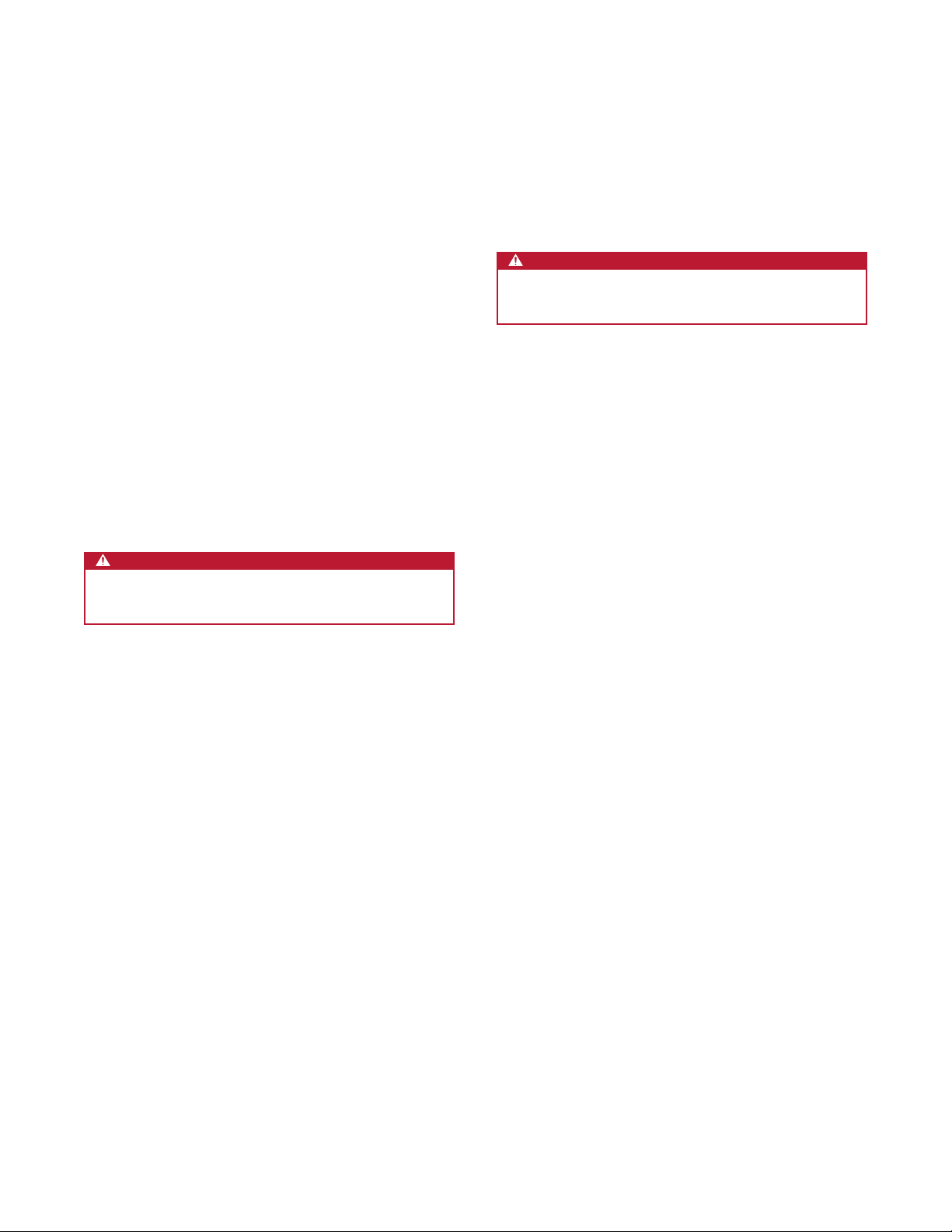
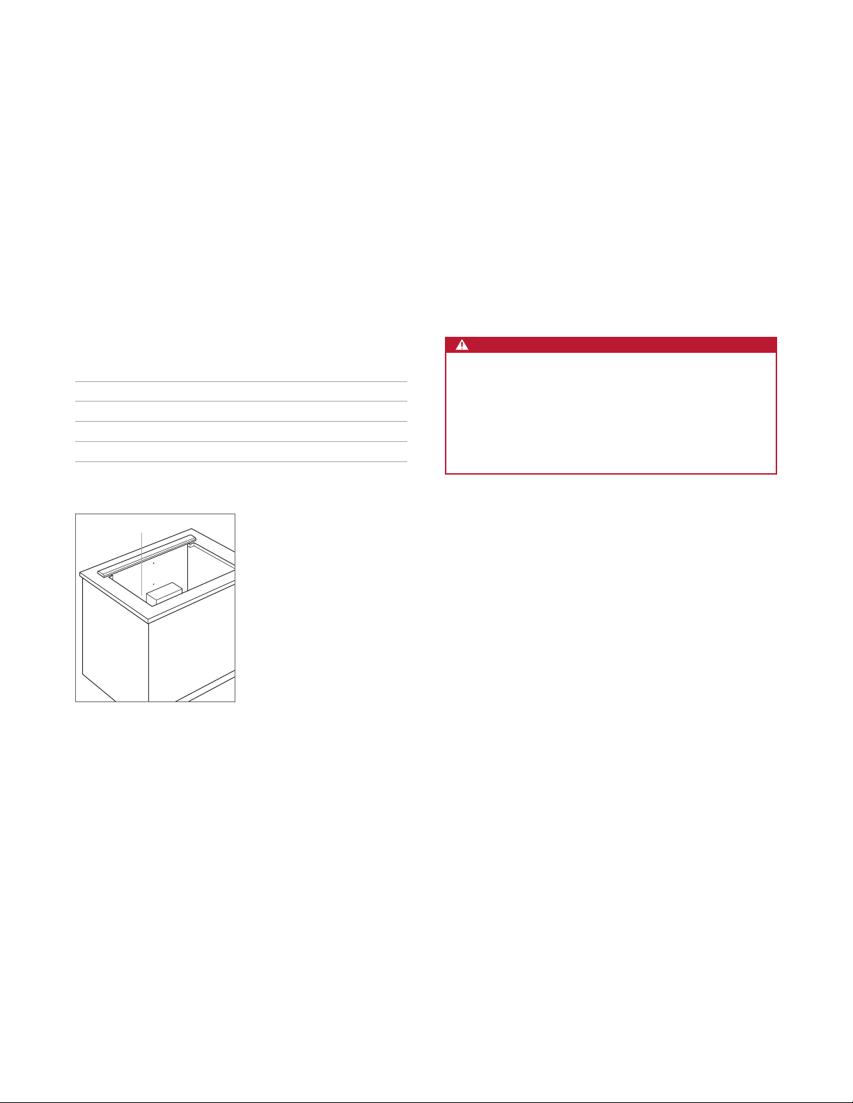
Electrical Requirements
Installation must comply with all applicable electrical codes.
Locate the electrical supply as shown in the illustrations
on the following pages. A separate circuit servicing only
this appliance is required. A ground fault circuit interrupter
(GFCI) is not recommended and may cause interruption of
operation.
Certain installations may require the electrical supply be
placed in an adjacent cabinet.
ELECTRICAL REQUIREMENTS
Electrical Supply grounded, 120 VAC, 60 Hz
Service 15 amp dedicated circuit
Receptacle 3-prong grounding-type
1
Power Cord 2
RATING PLATE
/2' (.8 m)
GROUNDING INSTRUCTIONS
This appliance must be grounded. In the event of an electrical short circuit, grounding reduces the risk of electric
shock by providing an escape wire for the electric current.
This appliance is equipped with a cord having a grounding
wire with a grounding plug. The plug must be plugged into
an outlet that is properly installed and grounded.
WARNING
Improper grounding can result in risk of electric shock.
Consult a qualied electrician if the grounding instructions are not completely understood, or if doubt exists
as to whether the appliance is properly grounded.
Do not use an extension cord. Have a qualied electrician install an outlet near the appliance.
Rating plate location
wolfappliance.com | 5
Page 6
SPECIFICATIONS
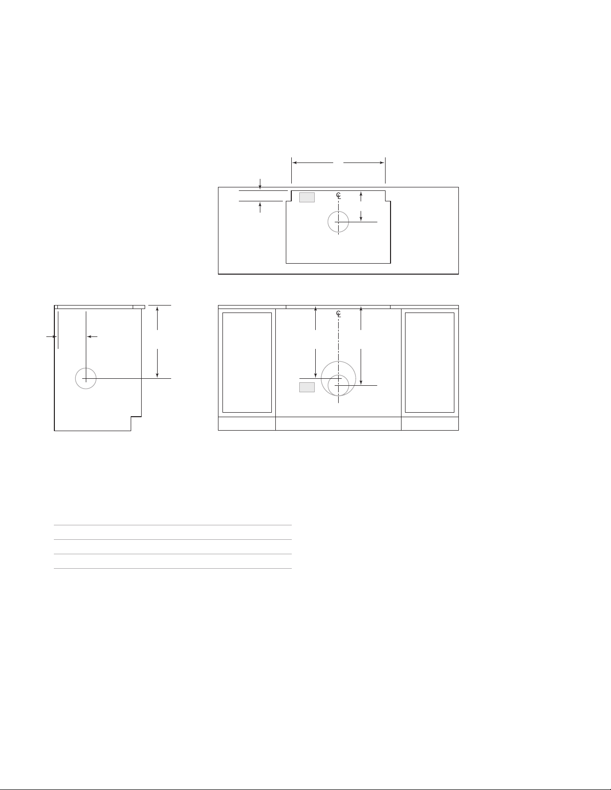
Downdraft
INSTALLATION WITH STANDARD INSTALLED COOKTOP
W
DOWNDRAFT
CUTOUT WIDTH
211/16" (68)
81/4"
(210)*
*6" (152) back from countertop cutout when internal blower is rear mounted.
NOTE: Internal blower 6"
Centerline indicates center of downdraft cutout.
211/4"
(540)
(152) round, side, rear or bottom discharge. In-line and remote blower 10" (254) round, rear discharge.
E
81/4" (210)*
COOKTOP CUTOUT
TOP VIEW
211/4"
(540)
233/8"
E
FRONT VIEWSIDE VIEW
(594)
CUTOUT WIDTH
DD30 271/2" (699)
DD36 331/2" (851)
DD45 391/2" (1003)
6 | Wolf Customer Care 800.222.7820
W
Page 7

SPECIFICATIONS
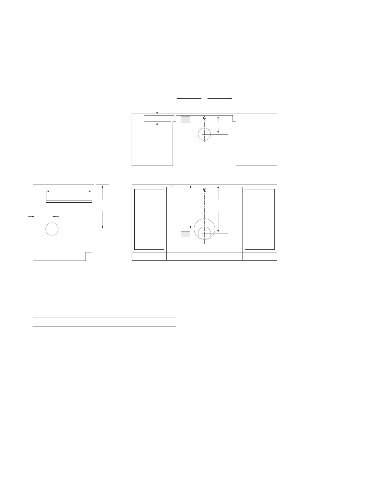
Downdraft
INSTALLATION WITH FLUSH INSTALLED COOKTOP
(59)
25/16"
W
DOWNDRAFT
CUTOUT WIDTH
E
81/4" (210)*
COOKTOP CUTOUT
TOP VIEW
81/4"
(210)*
*6" (152) back from countertop cutout when internal blower is rear mounted.
NOTE: Internal blower 6"
Centerline indicates center of downdraft cutout.
211/4"
(540)
(152) round, side, rear, or bottom discharge. In-line and remote blower 10" (254) round, rear discharge.
CUTOUT WIDTH
DD30 271/2" (699)
DD36 331/2" (851)
211/4"
(540)
233/8"
(594)
E
FRONT VIEWSIDE VIEW
W
wolfappliance.com | 7
Page 8
SPECIFICATIONS
Downdraft
INSTALLATION WITH SEALED BURNER RANGETOP
W
DOWNDRAFT
CUTOUT WIDTH
211/16" (68)
19" (483)
PLATFORM DEPTH
211/4"
(540)
81/4"
(210)*
*6" (152) back from countertop cutout when internal blower is rear mounted.
NOTE: Internal blower 6"
Centerline indicates center of downdraft cutout.
(152) round, side, rear, or bottom discharge. In-line and remote blower 10" (254) round, rear discharge.
E
81/4" (210)*
RANGETOP OPENING
TOP VIEW
211/4"
(540)
233/8"
(594)
E
FRONT VIEWSIDE VIEW
FRONT VIEWSIDE VIEW
CUTOUT WIDTH
DD30 271/2" (699)
DD36 331/2" (851)
8 | Wolf Customer Care 800.222.7820
W
Page 9
INSTALLATION
Installation
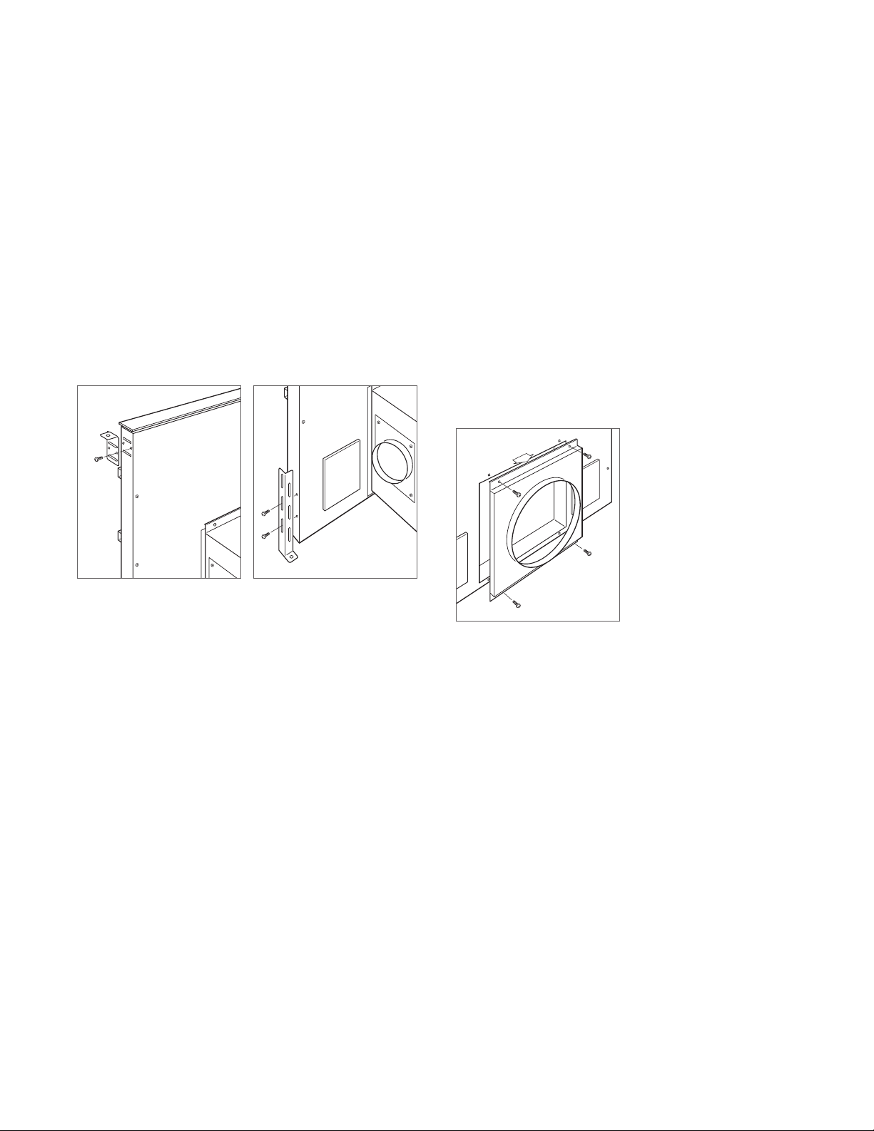
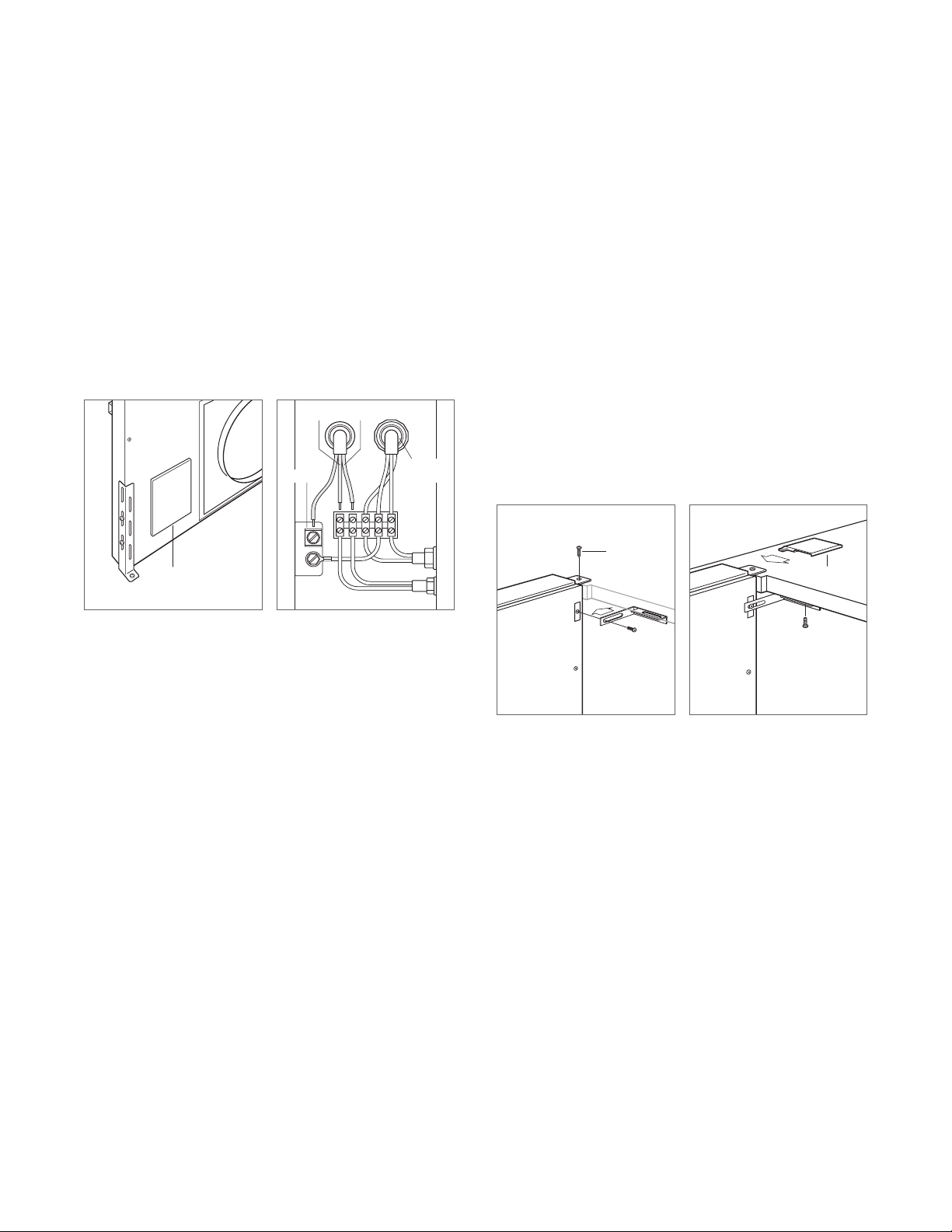
DOWNDRAFT
1 Install the top mounting brackets using the #4 sheet
metal screws provided. Refer to the illustration below.
2 Install the lower mounting brackets using the #8 x 32
sheet metal screws provided, but do not tighten. The
brackets need to be adjusted once the downdraft is
placed in the opening. Refer to the illustration below.
Top mounting bracket
Bottom leveling bracket
TRANSITION
For internal blowers, remove the existing 10" (254) round
transition. Refer to the illustration below.
For in-line and remote blowers with front discharge, leave
(254) round transition in place.
the 10"
For in-line and remote blowers with rear discharge, remove
(254) round transition from the front and the solid
the 10"
cover from the rear of the downdraft, then reinstall the transition on the rear and the solid cover on the front.
Remove transition
wolfappliance.com | 9
Page 10
INSTALLATION
Installation
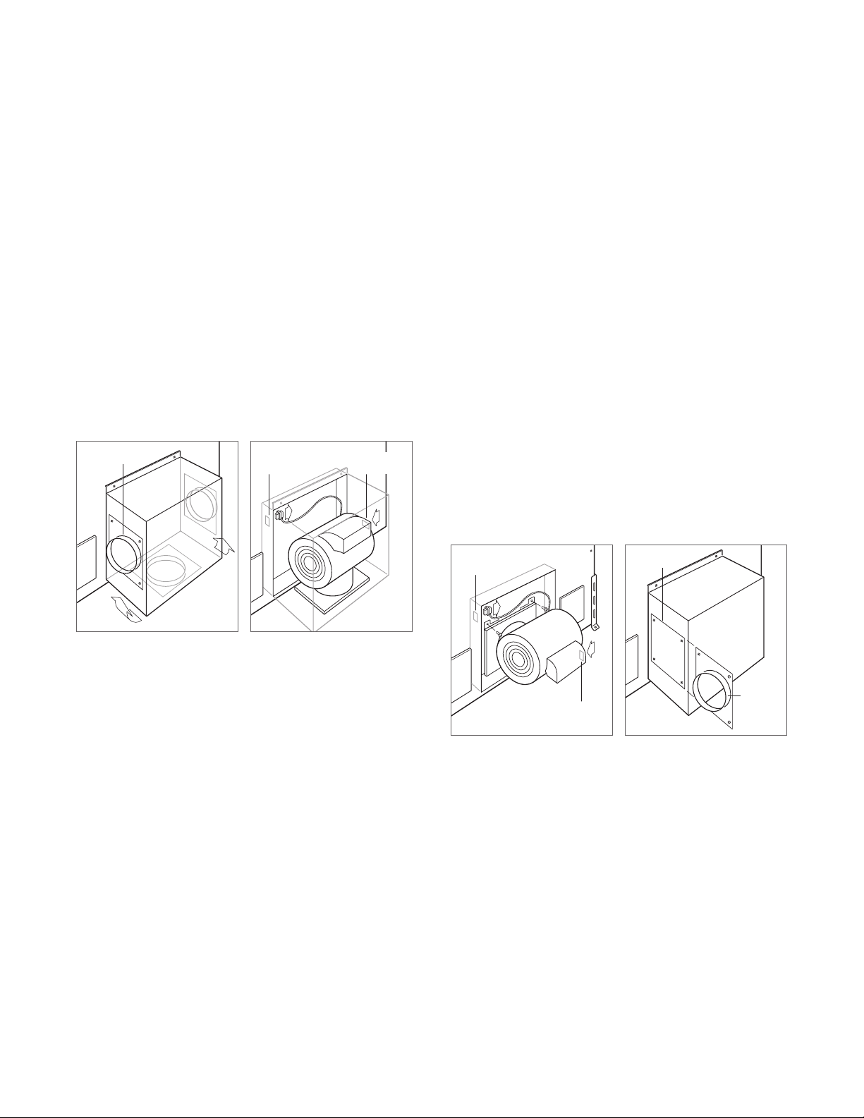
INTERNAL BLOWER
To mount the internal blower on the front or rear of the
downdraft:
1 Rotate the blower box so the 6" (152) round discharge
is properly located, then disconnect the cable from the
downdraft receptacle and connect it to the blower receptacle. Refer to the illustrations below.
2 Once the blower connection is made and the discharge
properly located, secure the blower to the downdraft
using the four screws provided.
DISCHARGE
DOWNDRAFT
RECEPTACLE
BLOWER
RECEPTACLE
To mount the internal blower on the front of the downdraft
but discharge from the rear:
1 Remove the blower from the blower box.
2 Mount the blower motor to the downdraft using the two
screws provided.
3 Remove the blower plug from the downdraft receptacle
and insert it into the blower receptacle. Refer to the illustration below.
4 Once the plug is installed and the blower secure, install
the blower box to the downdraft using the four screws
provided.
5 Remove the 6" (152) collar from the blower box and the
solid cover from the rear of the downdraft, then reinstall
(152) collar on the rear and the solid cover on the
the 6"
blower box. Refer to the illustration below.
DOWNDRAFT
RECEPTACLE
COVER
Left, right, or bottom discharge Blower connection
Blower mounting
BLOWER
RECEPTACLE
COLLAR
Install cover
10 | Wolf Customer Care 800.222.7820
Page 11
BLUE
BROWN
NEUTRAL
GROUND
HOT
POWER
SUPPLY
INSTALLATION
Installation
IN-LINE | REMOTE BLOWER
1 Insert the electrical supply (Romex) from the in-line or
remote blower through the opening on the downdraft
and secure using an approved cord strain relief.
2 Connect hot to brown, neutral to blue and ground to
green. Refer to the illustrations below.
WIRING
COVER
Wiring location
In-line | remote blower wiring
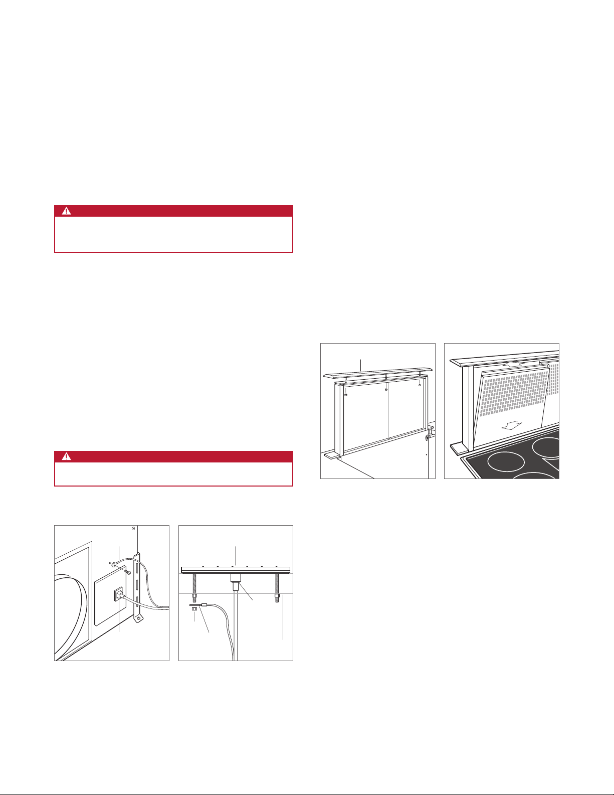
COUNTERTOP MOUNTING
Place the downdraft in the opening, then secure the bottom
brackets to the cabinet base using the wood screws provided. Once the brackets are secure, tighten the existing
lower bracket screws. Refer to the illustration below.
Secure the top mounting brackets to the countertop using
the wood screws provided. For solid surface countertops,
silicone may be used but is not provided.
Once the top is secure, install the undercounter brackets
using the screws provided, then install the side covers.
Refer to the illustration below.
MOUNTING
SCREW
COVER
Countertop mounting
Cover installation
wolfappliance.com | 11wolfappliance.com | 11
Page 12
MELT
HIGH
OFF ON
OFF ON
SIM
HIGH
OFF ON
SIM
HIGH
BRIDGE
OFF ON
SIM
HIGH
ZONE 2
CLEAR
OFF
O
ZONE 2
ZONE 3
HIGH
SIM
OFF ON
INSTALLATION
Installation
CONTROL MODULE
1 Use the template provided on the following page to mark
holes for the mounting screws. Drill one 1
3
center and two
/8" (10) holes for the mounting screws.
9
/16" (40) in the
CAUTION
Verify the scale of the template if not using the installation guide shipped with the downdraft.
2 Check the countertop thickness to make sure the
threaded studs are long enough to allow the thumbnuts
to fully engage. Thicker countertops may require the
countertop be countersunk from below.
3 Place the control module on the countertop then secure
using the two nuts provided. Once secure, install the
ground wire and nut.
4 Use the provided cable or a cable designated by the
National Electric Code, NFPA/ANSI 70 or local codes.
Connect one end of the control cable to the back side of
the control module and other to the electrical connection
on the front of downdraft assembly. Ensure all connections are tight.
TOP COVER
Plug the downdraft power cord into a grounded 3-prong
receptacle, then route beneath the appliance and away from
heat generated by the cooktop. Check downdraft operation.
Once operation is veried, raise the downdraft chimney and
install the top trim using the three nuts provided. Verify the
top trim is properly aligned with the side covers. Refer to the
illustration below.
FILTERS
Remove the stickers and shipping brackets and install the
lters. Refer to the illustration below.
TOP COVER
WARNING
Do not connect to a telecommunication network.
GROUND
RJ45
CONNECTOR
Downdraft connection
CONTROL MODULE
NUT
GROUND
Control module connection
RJ45
CONNECTOR
COUNTERTOP
Top cover installation
Filter installation
12 | Wolf Customer Care 800.222.7820
Page 13
INSTALLATION
Installation
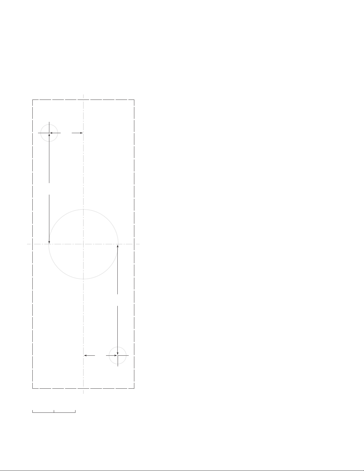
CONTROL MODULE TEMPLATE
13
/16
"
(21)
9
/16
2
"
(65)
C
L
9
/16
2
"
(65)
13
/16
"
(21)
C
L
1" (25)0"
SCALE
wolfappliance.com | 13
Page 14

TROUBLESHOOTING
Troubleshooting
IMPORTANT NOTE: If the downdraft ventilation system does
not operate properly, follow these troubleshooting steps:
• Verify electrical power is supplied to the downdraft.
• Verify proper electrical connections.
• If the downdraft does not operate properly, contact Wolf
Factory Certied Service. Do not attempt to repair the
downdraft. Wolf is not responsible for service required to
correct a faulty installation.
14 | Wolf Customer Care 800.222.7820
Page 15

Sub-Zero, Sub-Zero & Design, Sub-Zero & Snowake Design, Dual Refrigeration, The Living Kitchen, Great American Kitchens The Fine Art of Kitchen Design, Wolf, Wolf &
Design, Wolf Gourmet, W & Design, red colored knobs, Cove, and Cove & Design are registered trademarks and service marks of Sub-Zero Group, Inc. and its subsidiaries.
All other trademarks are property of their respective owners in the United States and other countries.
wolfappliance.com | 15
Page 16

VENTILACIÓN DE TIRO DESCENDENTE
Contenido
3 Ventilación de tiro descendente
4 Especicaciones
9 Instalación
14 Resolución de problemas
Las características y especicaciones están sujetas a cambios sin previo aviso. Visite wolfappliance.com/specs para
obtener la información más actualizada.
Aviso importante
Para garantizar que este producto se instale y opere de
la forma más segura y eciente posible, tome nota de los
siguientes tipos de información resaltada en esta guía:
AVISO IMPORTANTE señala la información que es especial-
mente importante.
PRECAUCIÓN indica una situación en la que se pueden
sufrir heridas leves o provocar daños al producto si no se
siguen las instrucciones.
ADVERTENCIA indica peligro de que se produzcan heridas
graves o incluso la muerte si no se siguen las precauciones.
AVISO IMPORTANTE: en toda esta guía, las dimensiones
entre paréntesis son milímetros, a menos que se especique lo contrario.
AVISO IMPORTANTE: guarde estas instrucciones para el
inspector eléctrico local.
2 | Atención al cliente de Wolf 800.222.7820
Page 17

VENTILACIÓN DE TIRO DESCENDENTE
Información del producto
La información importante del producto, incluido el modelo
y número de serie de la unidad, se encuentra en la placa
de datos del producto. La placa de datos se encuentra al
lado de la cubierta del extractor en la parte frontal del tiro
descendente, debajo del mostrador. Consulte la siguiente
ilustración.
Si necesita servicio, póngase en contacto con el centro de
servicio autorizado de Wolf y tenga a la mano el modelo y
número de serie de la unidad. Para obtener los datos del
centro de servicio autorizado de Wolf más cercano o si
tiene preguntas acerca de la instalación, visite la sección de
contacto y soporte técnico en nuestra página de Internet
wolfappliance.com o llame a la línea de atención al cliente
de Wolf al 800-222-7820.
PLACA DE DATOS
ADVERTENCIA
PARA REDUCIR EL RIESGO DE INCENDIO,
DESCARGA ELÉCTRICA O LESIONES A LAS
PERSONAS, OBEDEZCA LAS PRECAUCIONES
SIGUIENTES:
a)
Una persona calicada debe realizar el trabajo
de instalación y cableado eléctrico de conformidad con todos los códigos y normas aplicables, incluyendo la de construcción a prueba
de fuego.
b) Se necesita suciente aire para permitir una
combustión y escape de gases adecuados por
el humero (chimenea) del equipo quemador
de combustible para evitar que se produzcan
llamaradas. Siga las directrices del fabricante
del equipo de calefacción y las normas de
seguridad como las publicadas por la Asociación Nacional de Protección contra Incendios
(NFPA, por sus siglas en inglés) y la Sociedad
Estadounidense de Ingenieros en Calefacción,
Refrigeración y Aire Acondicionado (ASHRAE,
por sus siglas en inglés) y los códigos de las
autoridades locales.
Ubicación de la placa de datos
c) Al cortar o perforar la pared o el techo, no dañe
el cableado eléctrico ni otros servicios ocultos.
d) Los ventiladores con conductos siempre deben
descargarse hacia el exterior.
wolfappliance.com | 3
Page 18

ESPECIFICACIONES
Requisitos de instalación
Para instalarlo con una estufa Wolf, se necesita un mos-
1
trador plano de 25
/8" (638) de profundidad.
Para la instalación con un quemador sellado o una estufa
contemporánea de 30"
(762) o 36" (914), se necesita un kit
de accesorios de ribetes. Póngase en contacto con su distribuidor autorizado de Wolf para obtener más información.
Para obtener más información acerca de los distribuidores
locales, visite la sección para encontrar una sala de exposición de nuestro sitio web, wolfappliance.com.
El módulo de control montado en forma remota se puede
colocar horizontalmente o verticalmente. Debe colocarse
a menos de 9'
descendente y a un mínimo de 3"
(2.7 m) del montaje del ventilador de tiro
(76) del borde del recorte
de la estufa.
EXTRACTORES
PRECAUCIÓN
Para usarse con extractor interno Wolf 600 CFM y
extractores remotos con capacidad para 3 amperes
como máximo.
INSTALACIÓN DE CONDUCTOS
WARNING
PARA REDUCIR EL RIESGO DE INCENDIO, USE SOLAMENTE TUBERÍAS DE METAL.
Los ventiladores de tiro descendente Wolf deben ventilarse
hacia afuera. Consulte a un profesional de climatización
calicado para la instalación especíca y las aplicaciones
de conductos. La ventilación de tiro descendente tendrá
un funcionamiento más eciente con el menor número de
codos y transiciones y cuando los conductos no excedan
(12 m).
40'
Los extractores internos, en línea y remotos están disponibles a través de un distribuidor autorizado de Wolf.
Los extractores internos incluyen un escape circular de 6"
(152)
, que puede montarse al frente o en la parte posterior
y descargarse en cualquier dirección mediante la rotación
de la caja del extractor. Los extractores en línea y remotos
tienen un escape circular de 10"
(254) y puede descargarse
desde el frente o desde la parte posterior.
4 | Atención al cliente de Wolf 800.222.7820
Page 19

ESPECIFICACIONES
Instalación eléctrica
La instalación debe tener una conexión a tierra de conformidad
con los códigos locales o, en ausencia de códigos locales,
con el Código Nacional de Electricidad, ANSI/NFPA 70.
Coloque el suministro eléctrico tal y como se muestra en las
ilustraciones de las páginas 5 y 6. Es necesario un circuito
independiente que dé servicio únicamente a este aparato.
No es recomendable utilizar un circuito de fallos de conexión a tierra (GFCI, por sus siglas en inglés) ya que puede
interrumpir el funcionamiento de la unidad.
Ciertas instalaciones pueden requerir que el suministro eléctrico se encuentre en un gabinete adyacente.
REQUISITOS ELÉCTRICOS
Suministro eléctrico Con conexión a tierra, 120 V CA, 60 Hz
Servicio Circuito dedicado de 15 amperes
Receptáculo Conexión a tierra de 3 clavijas
1
Cable de alimentación eléctrica 2
PLACA DE DATOS
/2' (.8 m)
INSTRUCCIONES PARA REALIZAR LA CONEXIÓN A
TIERRA
Este electrodoméstico debe ser conectado a tierra. En caso
de que se produzca un cortocircuito eléctrico, la conexión a
tierra reduce el riesgo de descarga eléctrica al proporcionar
un cable de escape para la corriente eléctrica. Este electrodoméstico está equipado con un cable de alimentación
eléctrica con un enchufe de conexión a tierra. El enchufe
debe conectarse a un tomacorriente que esté correctamente instalado y conectado a tierra.
ADVERTENCIA
Una conexión a tierra incorrecta puede resultar en un
riesgo de descarga eléctrica. Consulte a un electricista
calicado si no entiende completamente las instrucciones de conexión a tierra o si tiene duda de que el
aparato esté conectado correctamente a tierra.
No utilice un cable de extensión. Si el cable de alimentación eléctrica es demasiado corto, pida a un electricista calicado que instale un tomacorriente cerca del
electrodoméstico.
Ubicación de la placa de datos
wolfappliance.com | 5
Page 20

ESPECIFICACIONES
Ventilador de tiro descendente
INSTALACIÓN CON COCINERO INSTALADO ESTÁNDAR
81/4"
(210)*
211/4"
(540)
211/16" (68)
ANCHURA DEL RECORTE
PARA EL VENTILADOR
DE TIRO DESCENDENTE
W
E
81/4" (210)*
RECORTE PARA ESTUFA
VISTA SUPERIOR
211/4"
(540)
233/8"
(594)
E
VISTA FRONTALVISTA LATERAL
*6" (152) detrás del recorte del mostrador cuando el extractor interno está montado en la parte posterior.
NOTA: extractor interno 6" (152) para descarga alrededor, a los lados, en la parte posterior o en la parte inferior. Extractor en línea y remoto
10" (254) para descarga alrededor o en la parte posterior. La línea central indica el centro del recorte del ventilador de tiro descendente.
ANCHURA DEL RECORTE
W
DD30 271/2" (699)
DD36 331/2" (851)
DD45 391/2" (1003)
6 | Atención al cliente de Wolf 800.222.7820
Page 21

ESPECIFICACIONES
Ventilador de tiro descendente
INSTALACIÓN CON COCINA INSTALADA EN LAVADO
81/4"
(210)*
211/4"
(540)
25/16"
(59)
ANCHURA DEL RECORTE
PARA EL VENTILADOR
DE TIRO DESCENDENTE
W
E
81/4" (210)*
RECORTE PARA ESTUFA
VISTA SUPERIOR
211/4"
(540)
233/8"
(594)
E
VISTA FRONTA LVISTA LATERAL
*6" (152) detrás del recorte del mostrador cuando el extractor interno está montado en la parte posterior.
NOTA: extractor interno 6" (152) para descarga alrededor, a los lados, en la parte posterior o en la parte inferior. Extractor en línea y remoto
10" (254) para descarga alrededor o en la parte posterior. La línea central indica el centro del recorte del ventilador de tiro descendente.
ANCHURA DEL RECORTE
W
DD30 271/2" (699)
DD36 331/2" (851)
wolfappliance.com | 7
Page 22

ESPECIFICACIONES
Ventilador de tiro descendente
INSTALACIÓN CON ESTUFA CON QUEMADORES SELLADOS
PROFUNDIDAD DE
LA PLATAFORMA
81/4"
(210)*
VISTA LATERAL
19" (483)
211/4"
(540)
211/16" (68)
ANCHURA DEL RECORTE
PARA EL VENTILADOR
DE TIRO DESCENDENTE
W
E
(210)*
81/4"
ABERTURA PARA ESTUFA
VISTA SUPERIOR
211/4"
(540)
233/8"
(594)
E
VISTA FRONTAL
*6" (152) detrás del recorte del mostrador cuando el extractor interno está montado en la parte posterior.
NOTA: extractor interno 6" (152) para descarga alrededor, a los lados, en la parte posterior o en la parte inferior. Extractor en línea y remoto
10" (254) para descarga alrededor o en la parte posterior. La línea central indica el centro del recorte del ventilador de tiro descendente.
ANCHURA DEL RECORTE
W
DD30 271/2" (699)
DD36 331/2" (851)
8 | Atención al cliente de Wolf 800.222.7820
Page 23

INSTALACIÓN
Instalación
VENTILADOR DE TIRO DESCENDENTE
1 Instale los soportes de montaje superior con los torni-
llos de metal #4 proporcionados. Consulte la siguiente
ilustración.
2 Instale los soportes de montaje inferior con los tornillos
de metal #8 x 32 proporcionados, pero no los apriete.
Los soportes deberán ajustarse una vez que el tiro
descendente se encuentre en la abertura. Consulte la
siguiente ilustración.
Soporte de montaje superior Soporte nivelador inferior
TRANSICIÓN
Para los extractores internos, retire la transición circular de
(254) existente. Consulte la siguiente ilustración.
10"
Para los extractores en línea y remotos que se ventilan
desde el frente, deje la transición circular de 10"
(254) en su
lugar.
Para los extractores en línea y remotos que se ventilan
desde la parte de atrás, retire la transición circular de 10"
(254)
de la parte frontal y la cubierta sólida de la parte posterior del tiro descendente, a continuación vuelva a instalar
la transición de 10"
(254) en la parte de atrás y la cubierta
sólida al frente.
Retire la transición
wolfappliance.com | 9
Page 24

INSTALACIÓN
RECEPTÁCULO
Instalación
EXTRACTOR INTERNO
Para montar el extractor interno al frente o en la parte de
atrás del tiro descendente:
1 Gire la caja del extractor de tal manera que el escape
circular de 6"
(152) se encuentre en el lugar apropiado, a
continuación desconecte el cable del receptáculo del tiro
descendente y conéctelo al receptáculo del extractor.
Consulte las siguientes ilustraciones.
2 Una vez que haya realizado la conexión del extractor y
el escape se encuentre correctamente ubicado, asegure
el extractor al tiro descendente con los cuatro tornillos
proporcionados.
DESCARGA
DEL VENTILADOR DE
TIRO DESCENDENTE
RECEPTÁCULO
DEL EXTRACTOR
Para montar el extractor interno en la parte frontal del tiro
descendente, pero el escape en la parte trasera:
1 Retire el extractor de la caja del extractor.
2 Monte el motor del extractor en el tiro descendente con
los dos tornillos proporcionados.
3 Retire el enchufe del extractor del receptáculo del tiro
descendente e insértelo en el receptáculo del extractor.
Consulte la siguiente ilustración.
4 Una vez que haya instalado el enchufe y el extractor esté
asegurado, instale la caja del extractor en el tiro descendente con los cuatro tornillos proporcionados.
5 Retire el collar de 6" (152) de la caja del extractor y la
cubierta sólida de la parte posterior del tiro descendente, a continuación vuelva a instalar el collar de 6"
(152)
en la parte posterior y la cubierta sólida en la caja
del extractor. Consulte la siguiente ilustración.
RECEPTÁCULO DEL
VENTILADOR DE
TIRO DESCENDENTE
CUBIERTA
Descarga a la izquierda,
Conexión del extractor
derecha o abajo
10 | Atención al cliente de Wolf 800.222.7820
RECEPTÁCULO
DEL EXTRACTOR
Montaje del extractor
COLLAR
Instale la cubierta
Page 25

INSTALACIÓN
AZUL
MARRÓN
NEUTRO
TIERRA
CALIENTE
Instalación
EXTRACTOR EN LÍNEA | REMOTO
1 Inserte el suministro eléctrico (Romex) del extractor en
línea o remoto por la abertura en el tiro descendente y
asegúrelo con un liberador de tensión aprobado.
2 Conecte el cable de la corriente al cable marrón, el
neutro al azul y la tierra al verde. Consulte la siguiente
ilustración.
SUMINISTRO
EL´ECTRICO
CUBIERTA DEL
CABLEADO
Ubicación del cableado
Cableado del extractor en
línea | remoto
MONTAJE DEL MOSTRADOR
Coloque el tiro descendente en la abertura, a continuación
asegure los soportes inferiores al gabinete con los tornillos
para madera proporcionados. Una vez que los soportes
estén asegurados, apriete los tornillos existentes del
soporte inferior. Consulte la siguiente ilustración.
Asegure los soportes de montaje superior al mostrador con
los tornillos para madera proporcionados. Para los mostradores de supercie sólida, puede utilizar silicón pero no se
proporciona como parte del paquete.
Una vez que la parte de arriba está asegurada, instale los
soportes bajo el mostrador con los tornillos proporcionados
y a continuación instale las cubiertas laterales. Consulte la
siguiente ilustración.
TORNILLO
DE MONTAJE
CUBIERTA
Montaje del mostrador
Instalación de la cubierta
wolfappliance.com | 11
Page 26

MELT
HIGH
OFF ON
OFF ON
SIM
HIGH
OFF ON
SIM
HIGH
BRIDGE
OFF ON
SIM
HIGH
ZONE 2
CLEAR
OFF
O
ZONE 2
ZONE 3
HIGH
SIM
OFF ON
INSTALACIÓN
Instalación
MÓDULO DE CONTROL
1 Utilice la plantilla proporcionada en la página 13 para
marcar los oricios para los tornillos de montaje. Taladre
9
un oricio de 1
/16" (40) en el centro y dos de 3/8" (10)
para los tornillos de montaje.
PRECAUCIÓN
Verique la escala de la plantilla si no va utilizar la guía
de instalación enviada con el tiro descendente.
2 Compruebe el grosor del mostrador para asegurarse de
que los pernos roscados son lo sucientemente largos
para permitir que las tuercas de mariposa engranen
completamente. Con mostradores más gruesos puede
ser necesario avellanar el mostrador desde abajo.
3 Coloque el módulo de control sobre el mostrador y a
continuación asegúrelo con las dos tuercas proporcionadas. Una vez asegurado, instale el cable a tierra y la
tuerca.
4 Utilice el cable proporcionado o un cable designado
por el Código Nacional de Electricidad, NFPA/ANSI 70
o los códigos locales. Conecte un extremo del cable de
control en la parte de atrás del módulo de control y el
otro a la conexión eléctrica al frente del montaje del tiro
descendente. Asegúrese de que todas las conexiones
estén bien ajustadas.
CUBIERTA SUPERIOR
Conecte el cable de alimentación del ventilador de tiro
descendente en un receptáculo de 3 clavijas, luego direccione por debajo del aparato y lejos del calor generado por
la estufa. Verique el funcionamiento del ventilador de tiro
descendente.
Una vez vericado el funcionamiento, levante la chimenea
e instale el ribete superior con las tres tuercas proporcionadas. Verique que el ribete superior esté correctamente
alineado con las cubiertas laterales. Consulte la siguiente
ilustración.
FILTROS
Retire las etiquetas y los soportes de transporte e instale los
ltros. Consulte la siguiente ilustración.
CUBIERTA SUPERIOR
ADVERTENCIA
No lo conecte a una red de telecomunicación.
TIERRA
CONECTOR
RJ45
Conexión del tiro descendente Conexión del módulo de control
12 | Atención al cliente de Wolf 800.222.7820
MÓDULO DE CONTROL
TUERCA
TIERRA
CONECTOR
RJ45
MOSTRADOR
Instalación de la cubierta
superior
Instalación del ltro
Page 27

INSTALACIÓN
L
Instalación
PLANTILLA DEL MÓDULO DE CONTROL
13
/16
"
(21)
9
/16
2
"
(65)
C
9
/16
2
"
(65)
13
/16
"
(21)
C
L
1" (25)0"
ESCALA
wolfappliance.com | 13
Page 28

RESOLUCIÓN DE PROBLEMAS
Resolución de problemas
AVISO IMPORTANTE: si el sistema de ventilación de tiro des-
cendente no tiene un funcionamiento apropiado, siga estos
pasos para resolver los problemas:
• Compruebe que el tiro descendente tenga corriente
eléctrica.
• Compruebe que las conexiones eléctricas son las
adecuadas.
• Si el tiro descendente no funciona correctamente, pón-
gase en contacto con el centro de servicio autorizado
de Wolf. No intente reparar el tiro descendente. Wolf no
es responsable del servicio necesario para corregir una
instalación defectuosa.
14 | Atención al cliente de Wolf 800.222.7820
Page 29

Sub-Zero, Sub-Zero & Design, Sub-Zero & Snowake Design, Dual Refrigeration, The Living Kitchen, Great American Kitchens The Fine Art of Kitchen Design, Wolf, Wolf &
Design, Wolf Gourmet, W & Design, red colored knobs, Cove, and Cove & Design son marcas registradas y marcas de servicio de Sub-Zero Group, Inc. y sus asociados. Todas
las demás marcas registradas son propiedad de sus dueños respectivos en los Estados Unidos y otros países.
wolfappliance.com | 15
Page 30

VENTILATION À ASPIRATION DESCENDANTE
Table des matières
3 Ventilation à aspiration descendante
4 Spécications
9 Installation
14 Dépannage
Les caractéristiques et les spécications peuvent être modiées en tout temps sans préavis. Visitez wolfappliance.com/
specs pour obtenir les renseignements les plus récents.
Remarque importante
Pour s´assurer que ce produit est installé et utilisé en toute
sécurité et aussi efcacement que possible, prenez note des
types de renseignement mis en évidence tout au long de ce
guide :
REMARQUE IMPORTANTE met en évidence des renseigne-
ments qui sont particulièrement importants.
MISE EN GARDE indique une situation où une blessure
mineure ou des dommages au produit peuvent se produire
si les directives ne sont pas respectées.
AVERTISSEMENT décrit un danger qui peut causer une
blessure grave ou la mort si les précautions ne sont pas
respectées.
REMARQUE IMPORTANTE : tout au long de ce guide, les
dimensions entre parenthèses sont en millimètres à moins
d´indication contraire.
REMARQUE IMPORTANTE : conservez ces directives pour
l´inspecteur en électricité local.
2 | Service à la clientèle de Wolf 800.222.7820
Page 31

VENTILATION À ASPIRATION DESCENDANTE
Renseignements sur le produit
Des renseignements importants sur le produit, y compris les
numéros de modèle et de série, se trouvent sur la plaque
signalétique du produit. La plaque signalétique est située à
côté du boîtier de la souferie sur le devant de l´aspiration
descendante, sous le comptoir. Reportez-vous à l´illustration
ci-dessous.
Si vous avez besoin de service, communiquez avec le
service Wolf certié par l´usine avec les numéros de modèle
et de série. Pour obtenir le nom du centre de service Wolf
certié par l´usine le plus près de chez vous ou si vous avez
des questions concernant l´installation, consultez la section
Contact et assistance de notre site Web, wolfappliance.com
ou appelez le service à la clientèle de Wolf au 800-222-7820.
PLAQUE SIGNALÉTIQUE
AVERTISSEMENT
EN VUE DE RÉDUIRE LE RISQUE D´INCENDIE,
DE CHOC ÉLECTRIQUE OU DE BLESSURES,
RESPECTEZ LES ÉLÉMENTS SUIVANTS :
a)
Le travail d´installation et le câblage électrique
doivent être effectués par une (des) personne(s) qualiée(s) conformément à tous les
codes et normes applicables, y compris ceux
concernant la construction résistante au feu.
b) Il faut sufsamment d´air pour la combustion
appropriée et l´évacuation des gaz dans la
sortie (cheminée) de l´équipement de chauffage
au mazout pour éviter le refoulement de l´air.
Suivez les directives du fabricant de l´équipement de chauffage et les normes de sécurité
comme celles publiées par la National Fire
Protection Association (NFPA ou association
nationale de protection contre les incendies),
l´American Society for Heating, Refrigeration
and Air Conditioning Engineers (ASHRAE ou
société américaine des ingénieurs de chauffage, réfrigération et climatisation) et les autorités locales concernant les codes.
Emplacement de la plaque
signalétique
c) Lorsque vous coupez ou percez dans un mur
ou un plafond, n´endommagez pas les ls électriques ou d´autres services publics cachés.
d) Les ventilateurs à enveloppe doivent toujours
être ventilés vers l´extérieur.
wolfappliance.com | 3
Page 32

SPÉCIFICATIONS
Exigences d´installation
Pour l´installation avec une surface de cuisson Wolf, un
1
comptoir plat d´au moins 25
/8 po (638) de profondeur est
requis.
Pour installation avec un plan de cuisson scellé ou une table
de cuisson contemporaine de 30 po
(762) ou 36 po (914), une
trousse de garniture accessoire est requise. Communiquez
avec votre dépositaire Wolf autorisé pour de plus amples
renseignements. Pour obtenir des renseignements sur le
dépositaire local, visitez la section salle d´exposition de
notre site Web, wolfappliance.com.
Le module de commande monté à distance peut être placé
horizontalement ou verticalement. Il doit se trouver à une
distance de 9 pi
cendante et à une distance d´au moins 3 po
(2.7 m) de l´assemblage de l´aspiration des-
(76) du rebord
de la surface de cuisson ou de la découpe du dessus de
cuisinière.
SOUFFLERIES
MISE EN GARDE
Pour utilisation avec la souferie interne Wolf 600 CFM
et les souferies à distance d´une capacité maximale
de 3 ampères.
RÉSEAU DE GAINES
WARNING
POUR RÉDUIRE LE RISQUE D'INCENDIE, UTILISEZ
SEULEMENT DES GAINES MÉTALLIQUES.
Les aspirations descendantes de Wolf doivent être ventilées vers l´extérieur. Consultez un professionnel en CVC
qualié pour des installations et des applications de gaines
précises. L´aspiration descendante fonctionnera de façon
plus efcace lorsqu´elle a le plus petit nombre de coudes et
lorsque l´ensemble de gaines ne dépasse pas 40 pi
(12 m).
Des assemblages de souferie interne, en ligne ou à distance sont offerts par votre dépositaire Wolf autorisé.
Les souferie internes comprennent une évacuation ronde
de 6 po
(152), peuvent être montées à l´avant ou à l´arrière
et peuvent être évacuées dans toute direction en pivotant la
boîte de la souferie. Les souferies en ligne et à distance
possèdent une évacuation ronde de 10 po
(254) et peuvent
être évacuées vers l´avant ou l´arrière.
4 | Service à la clientèle de Wolf 800.222.7820
Page 33

SPÉCIFICATIONS
Électricité
L´installation doit être mise à la terre électriquement
conformément aux codes locaux ou, en l´absence de codes
locaux, conformément au code national de l´électricité,
ANSI/NFPA 70.
Repérez l´alimentation électrique, comme il est montré dans
les illustrations aux pages 5 et 6. Un circuit séparé servant
uniquement cet appareil est requis. Un disjoncteur de fuite
de terre (GFCI) n´est pas recommandé et peut interrompre le
fonctionnement.
Certaines installations peuvent nécessiter que l´alimentation
électrique soit placée dans une armoire adjacente.
EXIGENCES ÉLECTRIQUES
Alimentation électrique mise à la terre, 120 volts CA, 60 Hz
Service circuit dédié de 15 ampères
Prise mise à la terre à trois broches
1
Cordon d´alimentation 2
PLAQUE SIGNALÉTIQUE
/2 pi (0,8 m)
DIRECTIVES DE MISE À LA TERRE
Cet appareil doit être mis à la terre. Dans le cas d´un
court-circuit, la mise à la terre réduit le risque de choc
électrique en fournissant un l de décharge au courant
électrique. Cet appareil est muni d´un cordon avec un l de
masse et une che de masse. La che doit être branchée
dans une prise qui est adéquatement installée et mise à la
terre.
AVERTISSEMENT
Une mauvaise mise à la terre peut entraîner un risque
de choc électrique. Consultez un électricien qualié si
vous ne comprenez pas complètement les directives
de mise à la terre ou si vous avez des doutes quant à la
mise à la terre appropriée de l´appareil.
N´utilisez pas de rallonge électrique. Si le cordon d´alimentation est trop court, demandez à un électricien
qualié d´installer une prise plus près de l´appareil.
Emplacement de la plaque
signalétique
wolfappliance.com | 5
Page 34

SPÉCIFICATIONS
Aspiration descendante
INSTALLATION AVEC LA TABLE DE CUISSON INSTALLEE STANDARD
81/4 po
(210)*
211/4 po
(540)
211/16 po (68)
LARGEUR DE LA DÉCOUPE DE
L’ASPIRATION DESCENDANTE
L
E
81/4 po (210)*
DÉCOUPE DE LA SURFACE
DE CUISSON
VUE DE DESSUS
211/4 po
(540)
233/8 po
(594)
E
VUE DE FACEVUE DE PROFIL
*6 po (152) de l’arrière de la découpe du comptoir lorsque la soufflerie interne est installée à l’arrière.
REMARQUE : soufflerie interne ronde de 6 po (152), évacuation latérale, arrière ou inférieure. Soufflerie en ligne et à distance ronde de
10 po (254), évacuation arrière. La ligne centrale indique le centre de la découpe de l’aspiration descendante.
LARGEUR DE LA DÉCOUPE
L
DD30 271/2 po (699)
DD36 331/2 po (851)
DD45 391/2 po (1003)
6 | Service à la clientèle de Wolf 800.222.7820
Page 35

SPÉCIFICATIONS
Aspiration descendante
INSTALLATION AVEC LA TABLE DE CUISSON INSTALLEE DE FLUSH
81/4 po
(210)*
211/4 po
(540)
25/16 po
LARGEUR DE LA DÉCOUPE DE
L’ASPIRATION DESCENDANTE
(59)
E
DÉCOUPE DE LA SURFACE
DE CUISSON
VUE DE DESSUS
211/4 po
(540)
E
VUE DE FACEVUE DE PROFIL
L
81/4 po (210)*
233/8 po
(594)
*6 po (152) de l’arrière de la découpe du comptoir lorsque la soufflerie interne est installée à l’arrière.
REMARQUE : soufflerie interne ronde de 6 po (152), évacuation latérale, arrière ou inférieure. Soufflerie en ligne et à distance ronde de
10 po (254), évacuation arrière. La ligne centrale indique le centre de la découpe de l’aspiration descendante.
LARGEUR DE LA DÉCOUPE
L
DD30 271/2 po (699)
DD36 331/2 po (851)
wolfappliance.com | 7
Page 36

SPÉCIFICATIONS
Aspiration descendante
INSTALLATION AVEC DESSUS DE CUISINIÈRE À BRÛLEUR SCELLÉ
PROFONDEUR DE
LA PLATE-FORME
81/4 po
(210)*
VUE DE PROFIL
19 po (483)
211/4 po
(540)
211/16 po (68)
LARGEUR DE LA DÉCOUPE DE
L’ASPIRATION DESCENDANTE
L
E
81/4 po (210)*
OUVERTURE DU DESSUS
DE CUISINIÈRE
VUE DE DESSUS
211/4 po
(540)
233/8 po
(594)
E
VUE DE FACE
*6 po (152) de l’arrière de la découpe du comptoir lorsque la soufflerie interne est installée à l’arrière.
REMARQUE : soufflerie interne ronde de 6 po (152), évacuation latérale, arrière ou inférieure. Soufflerie en ligne et à distance ronde de
10 po (254), évacuation arrière. La ligne centrale indique le centre de la découpe de l’aspiration descendante.
LARGEUR DE LA DÉCOUPE
L
DD30 271/2 po (699)
DD36 331/2 po (851)
8 | Service à la clientèle de Wolf 800.222.7820
Page 37

INSTALLATION
Installation
ASPIRATION DESCENDANTE
1 Installez les supports de montage supérieurs au moyen
des vis autotaraudeuses n° 4 fournies. Reportez-vous à
l´illustration ci-dessous.
2 Installez les supports de montage inférieurs en utilisant
les vis autotaraudeuses n° 8 x 32 fournies, mais ne
serrez pas. Les supports devront être ajustés lorsque
l´aspiration descendante sera placée dans l´ouverture.
Reportez-vous à l´illustration ci-dessous.
Support de montage supérieur Support de nivellement
inférieur
TRANSITION
Pour les souferies internes, retirez la transition ronde
existante de 10 po
(254). Reportez-vous à l´illustration
ci-dessous.
Pour les souferies en ligne et à distance évacuées vers
l´avant, laissez la transition ronde de 10 po
(254) en place.
Pour les souferies en ligne et à distance évacuées vers
l´arrière, retirez la transition ronde de 10 po
(254) de l´avant
et le couvercle plein de l´arrière de l´aspiration descendante,
puis réinstallez la transition de 10 po
(254) à l´arrière et le
couvercle plein à l´avant.
Retirez la transition
wolfappliance.com | 9
Page 38

INSTALLATION
PRISE DE
Installation
SOUFFLERIE INTERNE
Pour installer la souferie interne sur l´avant ou l´arrière de
l´aspiration descendante :
1 Pivotez la boîte de la souferie an que l´évacuation
ronde de 6 po
(152) soit correctement placée, puis
débranchez le câble de la prise de l´aspiration descendante et branchez-le sur la prise de la souferie.
Reportez-vous aux illustrations ci-dessous.
2 Une fois la connexion de la souferie effectuée et
l´évacuation correctement placée, xez la souferie
à l´aspiration descendante au moyen des quatre vis
fournies.
ÉVACUATION
PRISE DE L’ASPIRATION
DESCENDANTE
PRISE DE LA
SOUFFLERIE
Pour installer la souferie interne sur le devant de l´aspiration descendante, mais évacuer par l´arrière :
1 Retirez la souferie de la boîte de souferie.
2 Installez le moteur de la souferie sur l´aspiration des-
cendante au moyen des deux vis fournies.
3 Retirez la che de la souferie de la prise de l´aspiration
descendante et insérez-la dans la prise de la souferie.
Reportez-vous à l´illustration ci-dessous.
4 Une fois la che installée et la souferie xée, installez la
boîte de souferie sur l´aspiration descendante au moyen
des quatre vis fournies.
5 Retirez le collier de 6 po (152) de la boîte de souferie
et le couvercle plein de l´arrière de l´aspiration descendante, puis réinstallez le collier de 6 po
(152) à l´arrière
et le couvercle plein sur la boîte de souferie. Reportez-vous à l´illustration ci-dessous.
L’ASPIRATION
DESCENDANTE
COUVERCLE
Évacuation gauche, droite ou
Connexion de la souferie
inférieure
10 | Service à la clientèle de Wolf 800.222.7820
PRISE DE LA
SOUFFLERIE
Montage de la souferie
COLLIER
Installez le couvercle
Page 39

BLEU
BRUN
NEUTRE
MISE À
LA TERRE
CHAUD
INSTALLATION
Installation
SOUFFLERIE EN LIGNE | À DISTANCE
1 Insérez l´alimentation électrique (Romex) de la souferie
en ligne ou à distance dans l´ouverture de l´aspiration
descendante et xez au moyen d´un cordon approuvé
comme réducteur de tension.
2 Reliez le l chaud au brun, le l neutre au bleu et la
mise à la terre au vert. Reportez-vous à l´illustration
ci-dessous.
ALIMENTATION
´
ELECTRIQUE
COUVERCLE
DU CÂBLAGE
Emplacement du câblage
Câblage de la souferie en
ligne | à distance
MONTAGE SUR UN COMPTOIR
Placez l´aspiration descendante dans l´ouverture, puis xez
les supports inférieurs à la base de l´armoire au moyen des
vis à bois fournies. Une fois les supports xés, serrez les vis
du support inférieur existant. Reportez-vous à l´illustration
ci-dessous.
Fixez les supports de montage supérieurs au comptoir au
moyen des vis à bois fournies. Pour les comptoirs à surface
solide, de la silicone peut être utilisée, mais elle n´est pas
fournie.
Une fois le dessus xé, installez les supports de dessous du
comptoir au moyen des vis fournies, puis installez les couvercles latéraux. Reportez-vous à l´illustration ci-dessous.
VIS DE
MONTAGE
COUVERCLE
Montage sur le comptoir
Installation du couvercle
wolfappliance.com | 11
Page 40

MELT
HIGH
OFF ON
OFF ON
SIM
HIGH
OFF ON
SIM
HIGH
BRIDGE
OFF ON
SIM
HIGH
ZONE 2
CLEAR
OFF
O
ZONE 2
ZONE 3
HIGH
SIM
OFF ON
INSTALLATION
Installation
MODULE DE COMMANDE
1 Utilisez le gabarit fourni à la page 13 pour marquer les
trous pour les vis de montage. Percez un trou de 1
(40)
au centre et deux trous de 3/8 po (10) pour les vis de
9
/16 po
montage.
MISE EN GARDE
Vériez l´échelle sur le gabarit si vous n´utilisez pas le
guide d´installation expédié avec l´aspiration descendante.
2 Vériez l´épaisseur du comptoir pour vous assurer que
les tiges letées soient assez longues pour permettre
aux écrous à ailettes de s´enclencher complètement.
Des comptoirs plus épais pourront nécessiter le fraisage
du comptoir à partir du dessous.
3 Placez le module de commande sur le comptoir, puis
xez-le au moyen des deux écrous fournis. Un fois xé,
installez le l et l´écrou de mise à la terre.
4 Utilisez le câble fourni ou un câble désigné par le code
national de l´électricité, la norme NFPA/ANSI 70 ou les
codes locaux. Reliez une extrémité du câble de commande à l´arrière du module de commande et l´autre à
la connexion électrique située sur le devant de l´assemblage de l´aspiration descendante. Assurez-vous que
toutes les connexions soient bien serrées.
COUVERCLE SUPÉRIEUR
Branchez le cordon d'alimentation de l'aspiration descendante dans une prise à trois broches, puis acheminez-le
sous l'appareil et loin de la chaleur générée par la surface de cuisson. Vériez le fonctionnement de l'aspiration
descendante.
Une fois le fonctionnement vérié, relevez la cheminée et
installez la garniture supérieure au moyen des trois écrous
fournis. Vériez que la garniture supérieure est bien alignée
avec les couvercles latéraux. Reportez-vous à l´illustration
ci-dessous.
FILTRES
Retirez les autocollants et les supports d´expédition et installez les ltres. Reportez-vous à l´illustration ci-dessous.
COUVERCLE SUPÉRIEUR
AVERTISSEMENT
Ne reliez pas à un réseau de télécommunication.
MISE À LA
TERRE
CONNECTEUR
RJ45
Connexion de l´aspiration
descendante
12 | Service à la clientèle de Wolf 800.222.7820
MODULE DE COMMANDE
ÉCROU
MISE À LA
TERRE
Connexion du module de
commande
CONNECTEUR
RJ45
COMPTOIR
Installation du couvercle
supérieur
Installation du ltre
Page 41

INSTALLATION
L
Installation
GABARIT DU MODULE DE COMMANDE
13
/16
po
(21)
9
/16
2
po
(65)
C
9
/16
2
po
(65)
13
/16
po
(21)
C
L
1 po (25)0 po
ÉCHELLE
wolfappliance.com | 13
Page 42

DÉPANNAGE
Dépannage
REMARQUE IMPORTANTE : si le système de ventilation à
aspiration descendante ne fonctionne pas correctement,
suivez ces étapes de dépannage :
• Assurez-vous que l´aspiration descendante est
alimentée.
• Vériez les connexions électriques.
• Si l´aspiration descendante ne fonctionne pas correc-
tement, communiquez avec le service Wolf certié par
l´usine. Ne tentez pas de réparer l´aspiration descendante. Wolf n´est pas responsable du service requis pour
corriger une installation défectueuse.
14 | Service à la clientèle de Wolf 800.222.7820
Page 43

Sub-Zero, Sub-Zero & Design, Sub-Zero & Snowake Design, Dual Refrigeration, The Living Kitchen, Great American Kitchens The Fine Art of Kitchen Design, Wolf, Wolf &
Design, Wolf Gourmet, W & Design, les boutons de couleur rouge, Cove et Cove & Design sont des marques déposées et de service de Sub-Zero Group, Inc. et ses liales.
Toutes les autres marques de commerce appartiennent à leurs propriétaires respectifs aux États-Unis et dans d'autres pays.
wolfappliance.com | 15
Page 44

WOLF APPLIANCE, INC. P.O. BOX 44848 MADISON, WI 53744 WOLFAPPLIANCE.COM 800.222.7820
808256 REV-F 5/2018
 Loading...