

Page 1
subzero.com 800.222.7820
CT Gas Cooktop
Service Manual
General Information 2
Installation Information 6
Controls & Operation 13
Component Access & Removal 18
Troubleshooting Guide 26
Technical Data 29
Wiring Diagrams 31
Page 2
Gas Cooktop (CTG) Series
Gas Cooktop (CTG) Series
General Information
1-2
#802985 - Revision E - August, 2011
INTRODUCTION
This manual has been compiled to provide the most recent technical service information about this series. This
information will enable the service technician to troubleshoot and diagnose malfunctions, perform necessary repairs
and return a Wolf Gas Cooktop to proper operational condition.
The service technician should read the complete instructions contained in this Service/Training Manual before initiating any repairs on a Wolf Appliance.
* Some information in Section 2, Theory of Operation, has been provided by the American Gas Association
and reprinted with their approval.
IMPORTANT SAFETY INFORMATION
Below are the Product Safety Labels used in this manual. The "Signal Words" used are WARNING and
CAUTION.
Please note that these safety labels are placed in areas
where awareness of personal safety and product safety
should be taken and lists the precautions to be taken
when the signal word is observed.
INDICATES THAT HAZARDOUS OR UNSAFE
PRACTICES COULD RESULT IN SEVERE PERSONAL INJURY OR DEATH.
Indicates that hazardous or unsafe practices could
result in minor personal injury or product and/or
property damage.
In addition, please pay attention to the signal word
“NOTE”, which highlights especially important information within each section.
TECHNICAL ASSISTANCE
If you should have any questions regarding the appliance and/or this manual, please contact:
Wolf Appliance, Inc.
ATTN: Service Department
P.O. Box 44988
Madison, WI 53744 - 4988
Customer Assistance
Phone #: (800) 332 - 9513
Facsimile #: (608) 441 - 5887
Technical Assistance
(For Technicians in Customer’s Homes Only)
Phone #: (800) 919 - 8324
Warranty Claims
Phone #: (800) 404 - 7820
Facsimile #: (608) 441 - 5886
Service Department e-mail Address:
customerservice@wolfappliance.com
Main Office Hours:
8:00 AM to 5:00 PM Central Time
Monday through Friday
(24/7 Phone Coverage)
This manual is designed to be used by Authorized Service Personnel only. Wolf Appliance, Inc.. assumes
no responsibility for any repairs made to Wolf appliances by anyone other than Authorized Service
Technicians.
The information and images are the copyright property of Wolf Appliance, Inc., an affiliate of Sub-Zero, Inc. Neither
this manual nor any information or images contained herein may be copied or used in whole or in part without the
express written permission of Wolf Appliance, Inc., an affiliate of Sub-Zero, Inc. © Wolf Appliance, Inc. all rights
reserved.
Page 3
Gas Cooktop (CTG) Series
Gas Cooktop (CTG) Series
General Information
1-4
#802985 - Revision E - August, 2011
WARRANTY INFORMATION
This page contains a summary of the 2 & 5 Year
Warranty that is supplied with every Wolf product,
followed by details and notes about the warranties.
TWO & FIVE YEAR Warranty Summary
• Two year TOTAL PRODUCT warranty, parts and
labor.
• Limited Parts Only Warranty for the 3rd through
5th year on the following parts only:
• Gas Burners (excluding appearance).
Warranty Details:
The warranty applies only to products installed for
normal residential use. The warranty applies only to
products installed in the United States or Canada.
Warranty NOTES:
• All warranties begin at the time of the initial
installation.
• All Warranty and Service information collected by
Wolf Appliance, Inc.. is arranged and stored
under the unit serial number and/or the customer’s name. Please note that Wolf Appliance,
Inc. requests that you have the model serial
number available whenever contacting the factory or parts distributor.
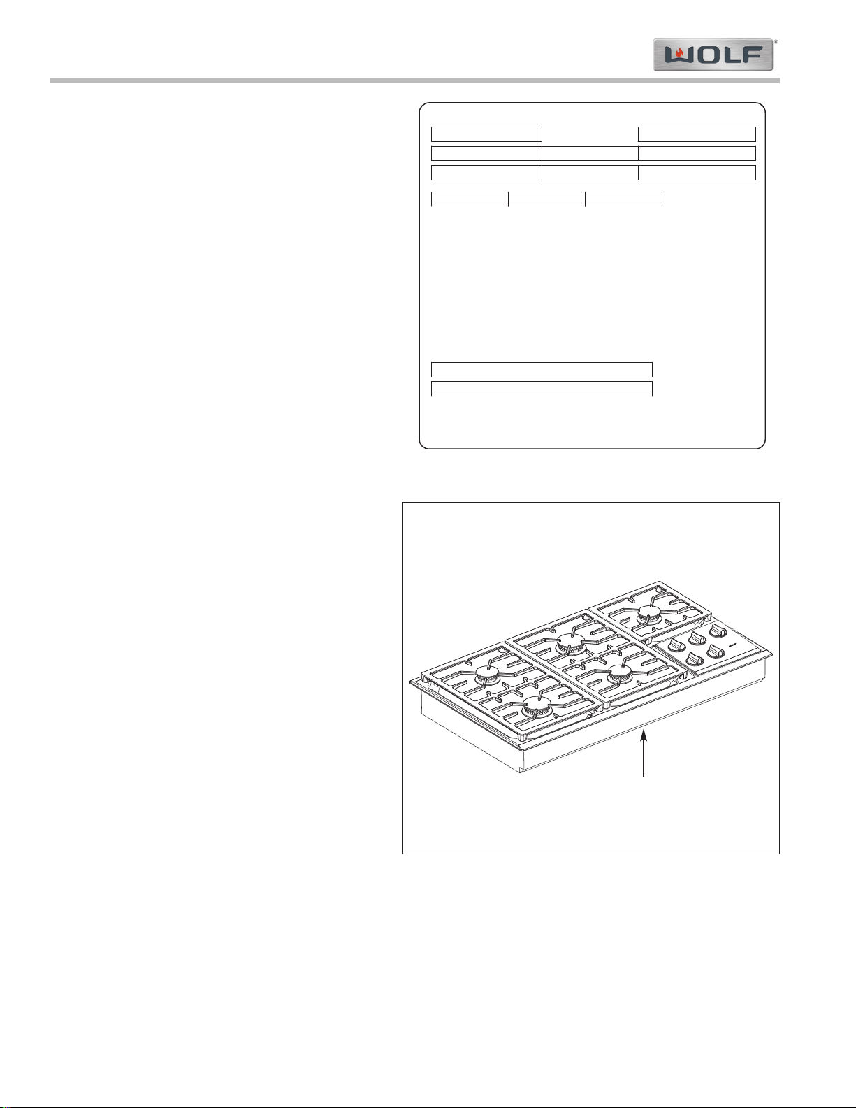
• See Figure 1-1 for serial tag layout.
• See Figure 1-2 for serial tag location.
Wolf Appliance Company, LLC
FITCHBURG, WI
GAS
LEFT
REAR
LEFT
FRONT
VOLTS
CENTER
REAR
CENTER
FRONT
AMP
PRESS.
MAIN
REAR
RIGHT
FRONT
RIGHT
HERTZ
ELECTRICAL RATING
000
000
60
INPUT RATING EACH
BURNER-BTU/HR.
MODEL
NO.
SERIAL
ANSI Z21.1 2000 "HOUSEHOLD GAS COOKING APPLIANCES"
"CAN1-1.1-M81"
BD
801503
Figure 1-1. Typical Serial Tag Layout
Figure 1-2. The serial tag is located on the bottom of
the cooktop.
Serial Tag Location
Page 4
General Information
Gas Cooktop (CTG) Series
Gas Cooktop (CTG) Series
1-5
#802985 - Revision E - August, 2011
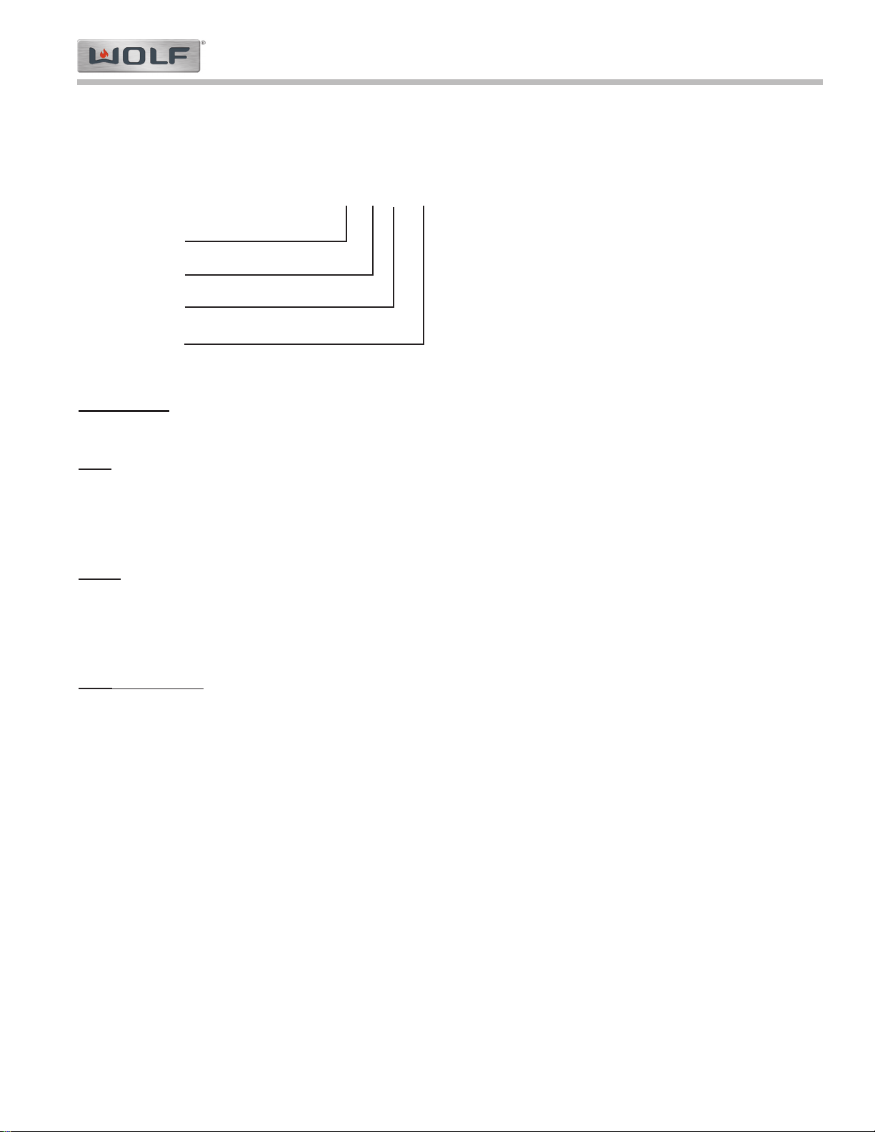
MODEL NUMBER KEY
Refer to this key for an example of the model numbers.
Model: CT 36 G / S
Product Type
Size
Fuel
Finish
Product T
ype
CT Cooktop
Size
15 15'' - inch wide unit
30 30'' - inch wide unit
36 36'' - inch wide unit
Finish
S Classic Stainless Steel
P Platinum Stainless Steel (Not Available for IM, IG, IS and IF)
B Carbon Stainless Steel (Not available for Gas models. Not available for IM, IG, IS and IF)
Fuel
(If Applicable)
LP Liquid Propane Gas
Natural Gas (If there is no “LP” at End of Model Number)
Page 5
Gas Cooktop (CTG) Series
Gas Cooktop (CTG) Series
General Information
1-6
#802985 - Revision E - August, 2011
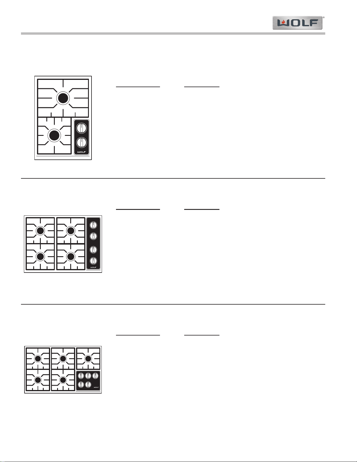
MODEL CONFIGURATIONS
Model Numbers
Descriptions
CT30G/S Cooktop 30” Gas Stainless Steel Natural Gas
CT30G/S- LP Cooktop 30” Gas Stainless Steel Propane
CT30G/P Cooktop 30” Gas Platinum Stainless Steel Nat Gas
CT30G/P- LP Cooktop 30” Gas Platinum Stainless Steel Propane
• Four burner
• Two burners at 12,000 BTU
700 BTU’S delivered at simmer
• Two burners at 9,200 BTU
300 BTU’s delivered at simmer
30” Gas
36” Gas
Model Numbers
Descriptions
CT36G/S Cooktop 36” Gas Stainless Steel Natural Gas
CT36G/S- LP Cooktop 36” Gas Stainless Steel Propane
CT36G/P Cooktop 36” Gas Platinum Stainless Steel Nat Gas
CT36G/P- LP Cooktop 36” Gas Platinum Stainless Steel Propane
• Five burner
• Two burners at 12,000 BTU
700 BTU’S delivered at simmer
• Three burners at 9,200 BTU
300 BTU’s delivered at simmer
Model Numbers Descriptions
CT15G/S Cooktop 15” Gas Stainless Steel Natural Gas
CT15G/S- LP Cooktop 15” Gas Stainless Steel Propane
• Two burner
• One burner at 12,000 BTU
700 BTU’S delivered at simmer
• One burner at 9,200 BTU
300 BTU’s delivered at simmer
15” Gas
Page 6

General Information
Gas Cooktop (CTG) Series
Gas Cooktop (CTG) Series
1-7
#802985 - Revision E - August, 2011
MODEL FEATURES for 15”, 30” & 36” GAS COOKTOPS
• Simmer on all burners
• Dual stacked sealed burners
• Single spark ignition with auto reignition for all burners
• 12,000 BTU/hr and 9,200 BTU/hr burners
• Low profile, continuous, porcelain-coated cast iron grates
• Smart porting of all burners
• Back lit illuminated control panel.
• Electric ratings: 110-120V/ 15 amp circuit
• Available in Natural or LP gas
• Two and Five year warranty
Page 7
Gas Cooktop (CTG) Series
Gas Cooktop (CTG) Series
Installation Information
2-2
#802985 - Revision E - August, 2011
INSTALLATION INFORMATION
This section of the manual covers some of the installation issues that a service technician may need to know when
servicing a Wolf Gas Cooktop. If additional installation information is needed after reviewing this section of the manual, please refer to the Installation Guide or contact the Wolf Appliance Customer Service Department.
Electrical Requirements:
• 110-120 volts AC, 60 Hertz, 15 ampere fused electrical supply.
• A timed-delay fuse or circuit breaker is recommended.
• Separate circuit serving only this appliance.
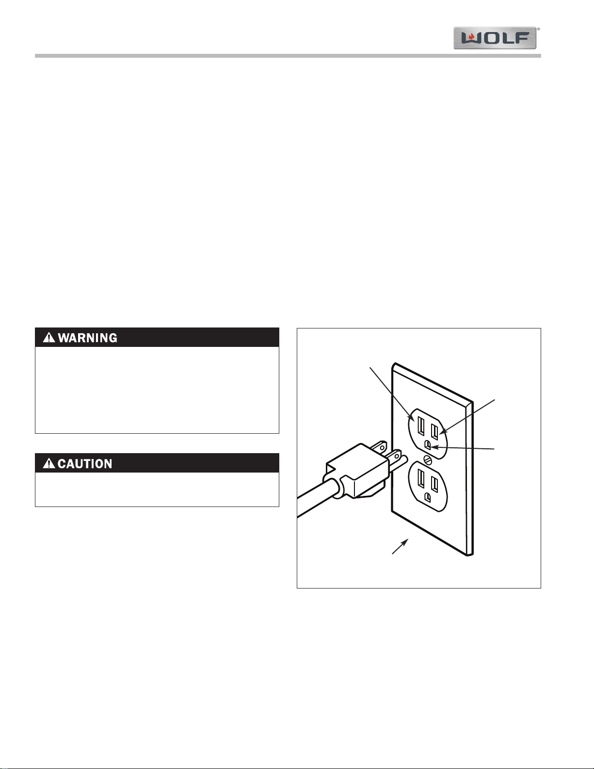
• Installation site must be equipped with a properly grounded 3-prong receptacle.
This appliance when installed must be properly grounded. This appliance is equipped with a 3-prong (grounding)
plug. The power cord must be plugged into a mating 3-prong ground-type receptacle (See Figure 2-1).
If a mating receptacle is not available, it is the obligation of the customer to have a properly grounded, 3-prong
receptacle installed by a qualified electrician.
If the electric receptacle or the power cord are not properly grounded and polarized, a shock hazard could exist and
the appliance may experience ignition problems.
• A SHOCK HAZARD COULD EXIST IF THE ELECTRIC RECEPTACLE OR THE POWER CORD ARE
NOT PROPERLY GROUNDED AND POLARIZED.
• TO AVOID SHOCK HAZARD, NEVER REMOVE
THE GROUNDING PRONG FROM THE PLUG OF
THE POWER CORD.
Figure 2-1. Proper Polarity at Electric Receptacle
Grounding Type
Wall Receptacle
Neutral
Ground
Line
Voltage
(Power)
The appliance may experience ignition problems if
not properly grounded and polarized.
Page 8
Installation Information
Gas Cooktop (CTG) Series
Gas Cooktop (CTG) Series
2-3
#802985 - Revision E - August, 2011
GAS REQUIREMENTS:
NOTE: All Wolf gas appliances are manufactured to
work with natural gas or LP gas (Liquid Propane gas).
Natural Gas Manifold Pressure
Standard natural gas orifices on the appliance are set
for 5” WC (Water Column Pressure).
Liquid Propane Manifold Pressure
The standard propane gas orifices on the appliance are
set for 10” WC (Water Column Pressure).
Gas Supply Line Size
• 1/2 inch
Gas Supply Pressure
• Maximum line pressure for natural gas and LP is
14” WC; 1/2 psi (3.5 kPa).
• Minimum line pressure for natural gas is 7” WC.
• Minimum line pressure for LP gas is 11” WC.
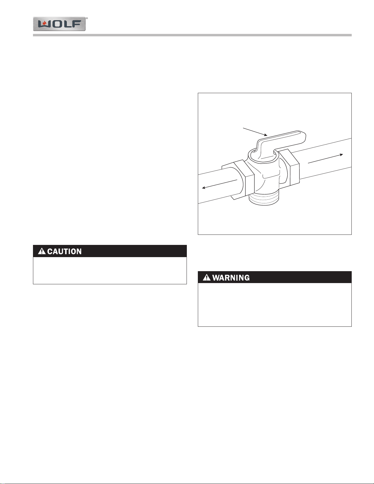
Gas Shut-off Valve
The supply line must be equipped with an approved
shut-off valve. This valve should be located in accordance to all national, local codes and ordinances (See
Figure 2-2).
NEVER USE OPEN FLAMES TO CHECK FOR GAS
LEAKS. ONLY USE A LEAK TESTING SOLUTION
OF SOAPY WATER OR AN ELECTRONIC LEAK
DETECTOR. DO NOT USE LIQUID NEAR VALVE
STEMS.
The maximum gas supply pressure to the regulator
should never exceed 14” WC (Water Column
Pressure); 1/2 psi (3.5kPa).
Shut-off Valve
(open position)
To Cooktop
Gas Supply Line
Figure 2-2. Shut-off Valve
Gas Pressure Regulator
To control and maintain a uniform gas pressure in thegas manifold, Wolf gas appliances must be connected
to the gas supply line through a pressure regulator.
The burner orifices are sized for the pressure delivered
by the regulator. Never attempt to operate a Wolf gas
appliance without the use of the proper pressure regulator.
Leak Testing
Page 9
Gas Cooktop (CTG) Series
Gas Cooktop (CTG) Series
Installation Information
2-4
#802985 - Revision E - August, 2011
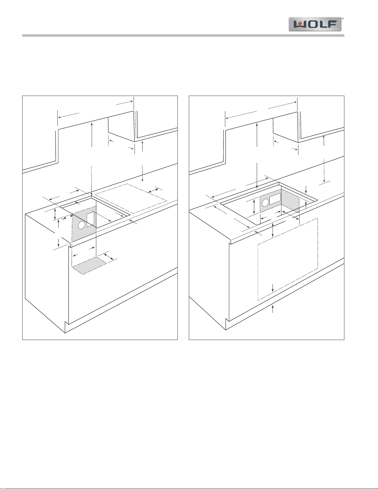
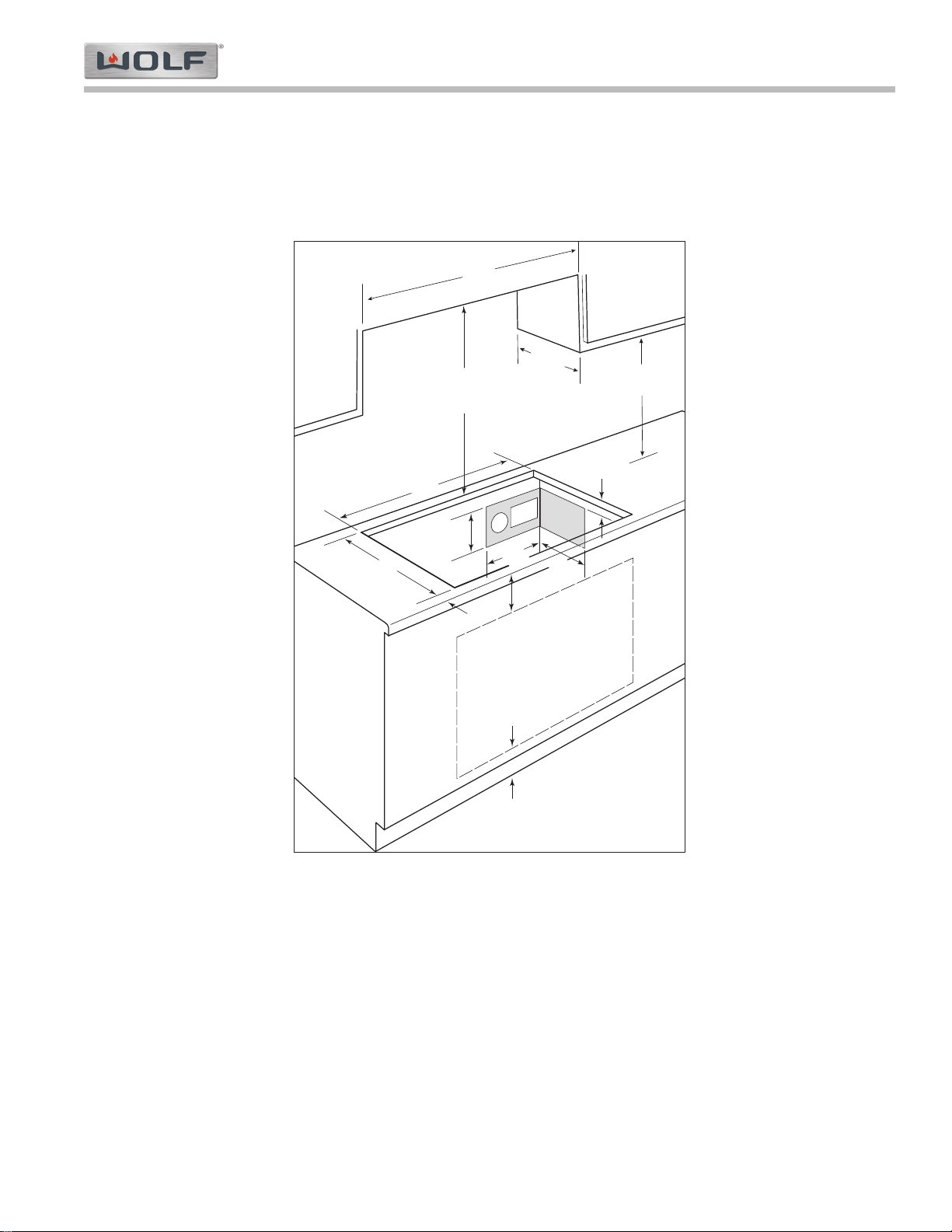
15” AND 30” GAS COOKTOP INSTALLATION DIMENSIONS
Area Requirements:
NOTE: Countertop opening dimensions that are shown must be used. Given dimensions provide required clear-
ances.
E
21/2"
min
(6.4)
15"
(38.1)
15"
(38.1)
14"*
(35.6)
4"
(10.2)
5"
(12.7)
G
* Dimensions may vary
by ± 1/8" (.3 cm)
13"
(33.0)
24" or 30"***
18"**
(45.7)
Combined width
of all cooktops
(61.0 or 76.2)
to cooking surface
7"
(17.8)
7"
(17.8)
"*
19
1
/
4
(49.0)
** 18” (45.7cm) minimum clearance upper cabinet to countertop within 7” (17.8cm) minimum side clearance to
combustible surface above countertop.
*** 24” (61cm) minimum clearance between top of cooking surface and bottom of wood or metal cabinet which is
protected by not less than 1/4” (.6cm) flame retardant millboard covered with not less than No. 28 MSG sheet
steel, .015” (.04cm) stainless steel, or .024” (.06cm) aluminum or .02” (.05cm) copper.
*** 30” (76.2) minimum clearance between top of cooking surface and bottom of an unprotected wood or metal
cabinet.
NOTE: Do not seal cooktop to countertop.
15” Installation Dimensions
E
31/2"
(8.9)
10"
(25.4)
4"
(10.2)
10"
(25.4)
29"*
(73.7)
191/4"*
(48.9)
21/2"
min
(6.4)
31/2"
min
(8.9)
30" oven cutout location
43/4"
min
(12.1)
E
G
* Dimensions may vary
by ± 1/8" (.3 cm)
30"
(76.2)
13"
(33.0)
24" or 30"***
(61.0 or 76.2)
18"**
(45.7)
to cooking surface
30” Installation Dimensions
Page 10
Installation Information
Gas Cooktop (CTG) Series
Gas Cooktop (CTG) Series
2-5
#802985 - Revision E - August, 2011
36” GAS COOKTOP INSTALLATION DIMENSIONS
Area Requirements:
NOTE: Countertop opening dimensions that are shown must be used. Given dimensions provide required clear-
ances.
** 18” (45.7cm) minimum clearance upper cabinet to countertop within 7” (17.8cm) minimum side
clearance to combustible surface above countertop.
*** 24” (61cm) minimum clearance between top of cooking surface and bottom of wood or metal cabinet which is
protected by not less than 1/4” (.6cm) flame retardant millboard covered with not less than No. 28 MSG sheet
steel, .015” (.04cm) stainless steel, or .024” (.06cm) aluminum or .02” (.05cm) copper.
*** 30” (76.2) minimum clearance between top of cooking surface and bottom of an unprotected wood or metal
cabinet.
NOTE: Do not seal cooktop to countertop.
36" oven cutout location
191/4"*
(48.9)
35"*
(88.9)
E
21/2"
min
(6.4)
31/2"
(8.9)
10"
(25.4)
4"
(10.2)
10"
(25.4)
31/2"
min
(8.9)
73/4"
min
(19.7)
E
G
* Dimensions may vary
by ± 1/8" (.3 cm)
36"
(76.2)
13"
(33.0)
24" or 30"***
(61.0 or 76.2)
18"**
(45.7)
to cooking surface
36” Installation Dimensions
Page 11
Gas Cooktop (CTG) Series
Gas Cooktop (CTG) Series
Installation Information
2-6
#802985 - Revision E - August, 2011
INSTALLATION PROCEDURE
• Insert cooktop into countertop opening and center
cooktop. Check that the front edge of the cooktop is
parallel to the front edge of the countertop. Check
that all required clearances are met.
• Use a pencil to outline the rear of the cooktop on
the countertop. Then remove cooktop from countertop.
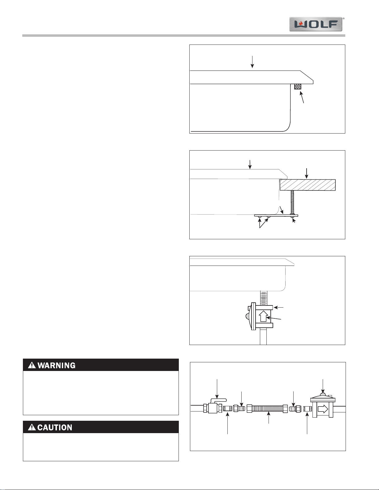
• Apply foam strip around bottom of burner box flush
with the edge (See Figure 3-8).
• Reinsert cooktop into the countertop opening.
Check that the cooktop is parallel to the front edge
of the countertop. Lift the entire cooktop to make
adjustments, aligning with the pencil line.
• Attach brackets to the burner box. Insert the
clamping screws into the brackets. Use a screwdriver to tighten clamping screws against the underside of the countertop (See Figure 3-8).
NOTE: Do not overtighten screws.
• Install the pressure regulator with the arrow on the
regulator pointing up towards the unit and in position where you can reach the access cap (See
Figure 3-9).
• Assemble the flexible metal connector from the gas
supply pipe to the pressure regulator (See Figure
3-10).
• Use a pipe-joint compound made for natural and
LP gas. If a flexible connector is used, be certain
the tubing is not kinked.
NOTE: All connections must be wrench tightened.
Do not make the connections to the regulator too
tight. Making the connections too tight could crack
the pressure regulator. Do not allow regulator to
turn on the pipe when tightening fittings.
• Open the shut-off valve in the supply line. Wait a
few minutes for the gas to move through the line.
• Leak testing of the appliance shall be conducted
accordingly using a soapy water solution or an
electronic leak detector.
The maximum gas supply pressure to the regulator
should never exceed 14” WC (Water Column
Pressure); 1/2 psi (3.5kPa).
NEVER USE OPEN FLAMES TO CHECK FOR GAS
LEAKS. ONLY USE A LEAK TESTING SOLUTION
OF SOAPY WATER OR AN ELECTRONIC LEAK
DETECTOR. DO NOT USE LIQUID NEAR VALVE
STEMS.
Regulator
Gas Flow
Arrow
Points Up
Rear of Burner Box
Figure 2-8. Foam Strip
Figure 2-10. Regulator Flow Arrow
Figure 2-11. Gas Connection
Manual
Shut-off Valve
1/2" Adapter 1/2" Adapter
Pressure
Regulator
1/2" Nipple
(use pipe-joint compound)
1/2" Nipple
(use pipe-joint compound)
Flexible Metal Connector
Burner Box
Cooktop Pan
Foam Strip
Cooktop Pan
Countertop
Burner Box
Bracket
Bracket Screws
3" (6.4cm)
Clamping Screw
Figure 2-9. Holding Clamp
Page 12

Installation Information
Gas Cooktop (CTG) Series
Gas Cooktop (CTG) Series
2-7
#802985 - Revision E - August, 2011
FILLER STRIP INSTALLATIONPROCEDURE (Refer to Figures 2-12 & 2-13 Below)
These instructions contain procedural information to install the Integrated Filler Strip Kit into countertop installations.
1. Locate the center of the Filler Strip Bracket (2) at the required distance from the cooktop cutout edge.
2. Position the Filler Strip Bracket (2) so that the top surface is flush with the counter top. You may need a straight
edge to assist in locating the bracket at the correct height.
3. Mark the center of the elongated slots of the Filler Strip Bracket (2) on the front and rear of the cooktop cutout.
4. Using a 3/32" drill bit, drill a ¾" deep pilot hole for the #6/32 (3) mounting screws.
5. Secure the Filler Strip Bracket (2) to the counter top.
14
5/8"
44
1/2"
15
1/4"
3
4
1
2
14
5/8"
Figure 2-13. Filler Strip with Two Integrated Cooktops and a 30" Gas or Electric Cooktop, Typical Installation
14 5/8"
59 1/2"
15 1/4"
29 5/8"
1
2
3
4
Figure 2-12. Filler Strip with Three Integrated Cooktops, Typical Installation.
PLEASE CONSULT WITH THE COUNTERTOP MANUFACTURER/INSTALLER FOR PROPER METHOD OF
INSTALLING SCREWS INTO INSIDE EDGE OF COUNTERTOP. DAMAGE MAY OCCUR IF PROPER METHODS
ARE NOT USED.
6. Install all cooktops into the corresponding openings.
7. Position the Filler Strip (1) into the Filler Strip Bracket (2) and install the three #10-24 nuts (4), but do not tighten.
8. Align and adjust cooktops and filler strips in the countertop opening and then tighten cooktop hold down clamps
and filler strip nuts.
Page 13

Gas Cooktop (CTG) Series
Gas Cooktop (CTG) Series
Installation Information
2-8
#802985 - Revision E - August, 2011
SUPPORT KIT FOR DOWNDRAFT INSTALLATION PROCEDURE (Refer to 2-14 Below)
These instructions contain procedural information to install the Integrated Cooktop Support Kit for downdraft ventilation installations.
NOTE: This kit does not include the Filler Strip Kit Assembly. Please order Kit Model number: 803386.
1. Locate and center the Rear Bracket Support (1) in the downdraft cutout as shown.
2. Position the Rear Bracket Support (1) so that the top surface is flush with the counter top. You may need a
straight edge to assist in locating the bracket at the correct height.
3. Mark the center of the elongated slots of the Rear Bracket Support (1) at both ends on the countertop.
4. Mark the center of the elongated slots of the Filler Strip Bracket (not included) on the front of the cooktop cutout.
5. Using a 3/32" drill bit, drill a 3/4" deep pilot hole for the #6/32 mounting screws (3)
Figure 2-14. Support Kit for DownDraft Ventilation Installation.
3
1
2
2
Filler Strip Bracket
Not Included
CENTER OF
CUTOUT
Filler Strip
Not Included
Not Included
6. Install the Downdraft into the countertop opening, but do not secure in place at this time.
7. Secure the Rear Bracket Support (1) and Filler Strip Bracket (not included) to the countertop using items (2 & 3).
8. Install Integrated cooktops into the corresponding openings.
9. Position the Filler Strip (not included) into the Filler Strip Bracket (not included) and install the three #10-24
nuts, but do not tighten.
10. Align and adjust cooktops, downdraft and filler strip in the counter top opening and then tighten cooktop hold
down clamps, filler strip nuts and secure the downdraft per installation instructions.
PLEASE CONSULT WITH THE COUNTERTOP MANUFACTURER/INSTALLER FOR PROPER METHOD OF
INSTALLING SCREWS INTO INSIDE EDGE OF COUNTERTOP. DAMAGE MAY OCCUR IF PROPER METHODS
ARE NOT USED.
Page 14

Gas Cooktop (CTG) Series
Gas Cooktop (CTG) Series
Theory of Operation
3-2
#802985 - Revision E - August, 2011
OPERATION INFORMATION
A service technician should understand how a gas appliance operates before attempting to service the appliance.
This section provides descriptions of the different types of fuel gases and explains gas heating values. A definition
of specific gravity of gas is given along with its characteristics and effects. Gas combustion principles are explained
and gas burner components are described and illustrated. The end of this section contains illustrations which
demonstrate basic cooking appliance theory of operation.
Types of Fuel Gas:
Gases used to supply heat energy are called fuel gases. Common fuel gases are not simply one kind of hydrocarbon, they are mixtures of hydrocarbon gases. They contain other gases as well, such as free hydrogen, carbon
dioxide and nitrogen. As an example, natural gas might contain 85% methane, 12% ethane and 3% of other gases.
The presence of each of these gases in the fuel gas has some effect on the nature of the gas.
Some common fuel gasses are methane [CH
4], ethane [C2H6], Propane [C3H8] and butane [C4H10]. Propane and
butane are nearly odorless. Natural gas that is processed to remove condensables and moisture, has little or no
odor and no color. Odorants are added to natural gas before distribution to aid in leak detection. A common odorant
used is a colorless liquid containing sulfur compounds.
Heating Value of Gas:
Heat energy produced when burning a fuel gas is commonly expressed in British Thermal Units (BTU). One BTU of
heat will raise the temperature of one pound of water one degree Fahrenheit.
The more carbon and hydrogen atoms in each molecule of a fuel gas, the higher its heating value. Natural gas
which is high in methane has a heating value of about 950 to 1150 BTU per cubic foot. The variance is due to the
various other substances found in natural gases. The more ethane, propane or butane in the gas raises the heating
value. Propane, or LP gas, has a heating value of about 2500-2800 BTU per cubic foot, and butane about 3200
BTU per cubic foot.
Specific Gravity of Gas:
The specific gravity of a gas is the weight of one cubic foot, or the gas compared to one cubic foot of dry air. When
stating the specific gravity of a gas, a pressure and temperature must be clearly stated. In the gas industry, the
standard conditions of pressure and temperature are 30.0 inches of mercury and 60° F. A pressure of 30.0 inches of
mercury will sustain a column of mercury 30 inches high in a tube with a vacuum on top of the column. Since air is
used as the reference, its specific gravity is always 1.0. This value of 1.0 has no direct physical meaning with
regard to air, such as its density. It is only a relative number or ratio used to express specific gravity of other gases.
The specific gravity of a gas will determine if the gas will rise or fall when released into the air. Natural gas will rise
since its specific gravity is less than 1.0 at 0.4 to 0.8. Propane has a specific gravity of 1.5 and butane 2.0. These
gases will fall when released into the air. They sometimes collect in low spots into pools which become a hazard if
open flames are present.
In addition, specific gravity has two other characteristics. It has an important effect on the flow of gases through orifices, and hence the rating of the burners. Gas flow through an orifice is dependent upon the orifice size and the
gas pressure upstream of the orifice. More of a lighter gas will flow through a given orifice size than a heavier gas
at the same gas pressure. This effect is taken into account in tables and calculators used to select orifice sizes for
burners.
Specific gravity also affects gas flow in pipes. A given driving pressure at a pipe inlet will move more lighter gas
than heavier gas through that pipe.
Page 15

Theory of Operation
Gas Cooktop (CTG) Series
Gas Cooktop (CTG) Series
3-3
#802985 - Revision E - August, 2011
PRINCIPLES OF GAS COMBUSTION:
Combustion - When oxygen acts with a substance to produce large amounts of heat rapidly.
Requirements for Combustion - There are three required elements for combustion to occur; Fuel (Gas), Oxygen
(Air) and Heat (Ignition Temperature, which for gas is between 1100°F/593°C and 1200°F/649°C). All must be present. Removing any one of the three and combustion will cease.
Chemistry of Combustion - Combustion of gas is a chemical reaction between fuel gas and oxygen. The basic
elements of common fuel gasses are hydrogen [H] and carbon [C]. When hydrogen burns, water vapor [H
2O] is pro-
duced. Complete burning of carbon in fuel gases form carbon dioxide [CO2] and water vapor [H2O].
Controlled Combustion - Controlled combustion takes place when gas and air are supplied at proper rates to
assure complete combustion of the gas in a steady flame. When a gas appliance is operating properly, burning
starts at the burner ports. Gas flow is controlled by gas orifice size and gas pressure upstream of the orifice. Air is
mixed with the gas before it passes through the burner ports. This added air is called “Primary Air”. The remaining
air required for complete combustion is supplied to the burner at the point of combustion and is called “Secondary
Air”.
Adjustments of the gas-to-air ratio and the secondary air supply is the key to obtaining stable blue flames at a burner. Proper amounts of primary and secondary air are required for quiet and efficient burner operation and for complete combustion of the gas. Air Shutters or other devices provide control of primary air. Inlet opening and flue outlets control Secondary Air flow.
Total air - In an ideal situation, primary and secondary air is all that is needed (for the oxygen required) to burn the
gas, but some additional air is required to assure complete burning of the gas. The total air, “primary”, “secondary”
and “excess” are expressed as percentages of the amount needed. About ten cubic feet of air is required to completely burn one cubic foot of gas. For this reason an appliance should not be operated in an air tight home.
Limits of Flammability - Not all air-to-gas mixtures will burn. Mixtures with 0% - 4% natural gas in air are too lean
to burn. Mixtures of 4% - 14% natural gas in air can burn with a controlled flame. Flammability limits come into play
when primary air adjustments are made on burners. If too much primary air is used, the mixture may become too
lean and fall below flammability limits, thus preventing combustion.
Incomplete Combustion (Causes and Effects) - To obtain complete combustion, sufficient amounts of air must be
supplied to the process. This air must have a reasonably normal oxygen content. Complete burning of gas produces harmless carbon dioxide gas and water vapor. If the air supply is insufficient, incomplete combustion occurs
resulting in the formation of toxic by-products, such as carbon monoxide [CO] or aldehydes.
Carbon monoxide is colorless and odorless. Inhaling carbon monoxide in sufficient quantities could cause death by
reducing oxygen levels in the blood.
Aldehydes, which are equally dangerous, have a sharp and penetrating odor which is easily detected by smell at
very low concentrations. The odor caused by aldehydes should not be confused with odorants added to natural gas.
The absence of aldehydes does not assure that carbon monoxide is not present. However, if the odor of aldehydes
is present, then carbon monoxide is virtually always present.
Gas Burner Operation - A gas burner is a device to burn gas under control in order to produce useful heat.
Primary air is brought into the burner from outside of the appliance at atmospheric pressure. The gas jet streaming
from the orifice draws primary air with it into the burner.
The gas/air mixture, combined with a spark at the burner port(s) and the secondary air creates a controlled burn.
Page 16

Gas Cooktop (CTG) Series
Gas Cooktop (CTG) Series
Theory of Operation
3-4
#802985 - Revision E - August, 2011
BURNER COMPONENTS for 15”, 30” and 36”
Burner Head - The component containing the burner ports where the gas/air mixture ignites. The burner ports are
distributed in a useful pattern to optimize heat transfer. The flames should be spread so they can be easily reached
by secondary air and provide a stable blue flame.
Venturi - Threaded brass pipe that threads into the jet holder through the distribution rings which narrows and then
flares out again. This pipe helps maintain proper and constant primary air injection.
Inner Distribution Ring - Routes the gas from the simmer orifice hood to the simmer port holes located on the
burner cap.
Outer distribution Ring - Routes the gas from the main burner orifice hood to the main burner port holes on the top
of the burner head.
Jet Holder - This component is mounted to the burner mounting bracket and to the burner box. The main burner
orifice is threaded into the jet holder as well as the venturi. It is the main support for the burner components.
Gas Orifice - An opening or hole which regulates or limits the amount of gas flowing to a burner. Gas flow rate (volume) depends on the size of the orifice (hole) and the gas pressure at the inlet of the orifice.
15”, 30” and 36” Burner Components
Burner Head
Venturi
Inner Distribution Ring
Outer Distribution Ring
With Connector and
Orifice
Jet holder with Orifice
Page 17

Theory of Operation
Gas Cooktop (CTG) Series
Gas Cooktop (CTG) Series
3-5
#802985 - Revision E - August, 2011
OPERATION OF THE 15”, 30” and 36” WOLF GAS COOKTOP
Surface Burners
A spark electrode ignites each surface burner. This control eliminates the need for continuous open flame pilots.
For added safety and convenience, each burner is designed with an electronic re-ignition system. This feature
enables any burner to automatically re-light in the event it is accidentally extinguished.
This cooktop has a unique dual stacked burner design that combines all the burner parts in one configuration. Large
burners provide a Btu/hr rating of 12,000 on HIGH. On small burners the Btu/hr rating is 9,200 on HIGH. All burners have simmer settings.
A distinguishing feature of Wolf’s low Btu/hr control is its constant, low heat output without continuous ignitions.
Flame diameter remains full size, only the heat output is lowered. This is the ultimate control for simmering food.
After removing burner parts for any reason, it is extremely important that the burners are re-assembled correctly.
The burner cap has a special orientation and should be seated flatly. Rotate burner cap until you feel it drop and
click into position.
This patent pending dual stacked burner configuration makes it possible to enjoy cooking at full flame as well as
maintaining control while simmering at the lowest flame setting.
Grate Placement
Low profile cast iron grates are designed for a close fit. This enables pans to move easily from one burner to another without having to lift the pan or have it tip over between the grates. Each grate sets securely on dimples on each
corner of the cooktop pan. Continuous grates are interchangeable with the exception of the single grate.
Control Knobs
Each knob is positioned to correspond to the burner regulated. For the 36-inch cooktop, the knob on the lower left
side regulates the lower left burner. Conversely, the knob on the upper right side regulates the upper right burner.
Each knob on the 30-inch cooktop control panel has a diagram above it. The diagram shows which knob to regulate.
It is normal for the knobs to be slightly elevated above the control panel surface. This space is an air inlet necessary for good combustion of gas. Each knob rests on a valve stem with a rubber grommet at the base. This design
prevents liquid spills from dripping into the controls below the burners.
Burner Lighting
Each burner has full flame and full simmer capabilities. Knobs are designed as a two- tiered, “push-to-turn” knob.
One tier is used for HIGH through LOW flame settings. The second tier controls SIMMER settings.
Push down and turn the corresponding control knob counter clockwise to the HIGH setting. You will hear “clicking”
and see the burner ignite. Once the burner is lit, continue turning the knob counter clockwise to any one of the settings, HIGH through LOW.
To select a simmer setting, turn the knob to the LOW setting. You will feel a stop-detente in the knob rotation. Push
down on the knob, continuing to turn it counter clockwise. This moves it to the second tier. Now, select any variation within the SIMMER flame settings, HIGH through LOW.
Illuminated Control Panel
This unique feature of the cooktop is an instant visual indicator that one or more burners are in use. It is also a
safety signal reminder that a flame is on and active.
Page 18

Gas Cooktop (CTG) Series
Gas Cooktop (CTG) Series
Theory of Operation
3-6
#802985 - Revision E - August, 2011
Burner Spill Tray
Exterior Finish
Burner Cap
Burner Grates
Control Knobs
Control Panel
Spark Igniters
Part Identification
CLEANING and MAINTENANCE
15”, 30” and 36” Gas Cooktop
Material Care Recommendation
Stainless steel
Although resistant to most
stains, it is not totally impervious to damage. Salt and
some cooking liquids may pit
and stain surface. Always
remove these spills immediately.
Avoid using abrasive cleaners;
they will permanently scratch
the surface.
Porcelain enamel (matte finish)
Never wipe a warm or hot
porcelain surface with a damp
sponge; it may cause chipping
or crazing (tiny hair-like cracks)
Porcelain-coated cast iron
Chrome-plated
Tempered glass
Ceramic
General care: Use a clean cloth or sponge, wipe
with warm water and mild detergent. Rinse and
dry immediately. Apply protective polish, always in
the same direction.
Spray degreaser: Removes fingerprints and
greasy spatters. Spray on a cloth and wipe surface. Buff dry immediately to avoid streaking.
Protective polish: Apply to surface to maintain luster and protect from some food stains
Hard water stains: Use white vinegar and water.
Cool first. Wash in warm water with liquid detergent or mild abrasive cleaners.
Foods high in acid or sugar content, such as milk,
tomatoes, sauerkraut, fruit juices and pie filling,
may pit or craze the surface. Remove as soon as
possible. Do not cook the spill on again.
Remove from cooktop and place on a flat surface
near the sink.
Non-abrasive cleaners: Hot water and liquid detergent, paste of baking soda and water, plastic pad
or sponge.
Mild abrasive and abrasive cleaners: Use sparingly.
To remove the knobs, slip the edge of a dishtowel
under the knob; pull the edge together. Using the
towel for leverage, lift up; the knob pulls off of the
valve stem.
General care: Wipe each knob with a damp cloth
and mild soap and water; rinse and dry. Never
soak or use abrasive cleaners; they will scratch the
finish and remove the markings.
Spray cleaners: Removes fingerprints and greasy
food soils. Spray first on a cloth before wiping
panel.
Keep dry Never spray water or cleaner directly on
the igniter. When cleaning around the surface
burner, be careful that the cloth does not catch on
the igniter and damage it.
Page 19

Gas Cooktop (CTG) Series
Gas Cooktop (CTG) Series
Component Access & Removal
4-2
#802985 - Revision E - August, 2011
COMPONENT ACCESS AND REMOVAL
This section explains how to access and remove components from a Wolf Gas Cooktop. Depending on which component you are going to access or remove in the following sections, you may have to remove other components first.
Refer to the appropriate section in this manual that explains how to access and remove those various components.
When reassembling, just reverse the steps that were used to access and remove the components.
NOTE: Before attempting to access or remove any components from a Wolf Appliance, take note of the following
warnings.
• TO AVOID SERIOUS BURNS AND/OR EXPLOSIONS, KEEP COMBUSTIBLES AWAY FROM THE APPLIANCE
WHENEVER A FLAME IS PRESENT. REMEMBER THAT SURFACES AND COMPONENTS GET HOT DURING
THE USE OF THE APPLIANCE.
• TO AVOID ELECTRICAL SHOCK, POWER TO THE UNIT MUST BE DISCONNECTED WHENEVER ACCESSING AND/OR REMOVING COMPONENTS POWERED BY ELECTRICITY OR COMPONENTS NEAR OTHER
ELECTRICAL COMPONENTS.
• TO AVOID HAZARDOUS EXPLOSION OR GAS LEAKS, GAS TO UNIT MUST
BE TURNED OFF AT THE GAS
SUPPLY SOURCE WHENEVER ACCESSING AND/OR REMOVING COMPONENTS.
• TO ENSURE PROPER BURNER OPERATION, THE O-RINGS MUST BE REPLACED ANY TIME THE UNIT IS
DISASSEMBLED FOR ANY REASON.
• WHEN REASSEMBLING GAS SUPPLY LINE TO REGULATOR, ONLY PIPE THREAD COMPOUND SHOULD
BE USED. DO NOT USE TEFLON TAPE TO SEAL GAS PIPE CONNECTIONS.
• WHEN REASSEMBLING REGULATOR TO MANIFOLD, ONLY PIPE THREAD COMPOUND SHOULD BE USED.
DO NOT USE TEFLON TAPE TO SEAL GAS PIPE CONNECTIONS.
Page 20

Component Access & Removal
Gas Cooktop (CTG) Series
Gas Cooktop (CTG) Series
4-3
15”, 30” AND 36” GAS COOKTOP
Surface Burner Components:
Surface Burner Grate, Burner Head with Cap,
Venturi, Inner Distribution Ring, Spark Electrode,
Outer Distribution Ring, Jet Holder and Burner
Mounting Bracket
Preliminary Steps:
• Disconnect the power cord from the electrical supply source.
• Turn off the gas supply source to the cooktop.
• Lift the surface burner grate from the cooktop pan.
Burner Head with Cap Removal
The burner head consists of a top and bottom layer of
holes. When main burner heat is required, the gas
travels through the main burner orifice hood (mounted
to the jet holder), then through the venturi to the burner
head and then out the top layer of holes. When simmer
heat is required, the gas travels through the simmer orifice hood (located on the side of the outer distribution
ring), up through the outer portion of the inner distribution ring, then to the bottom layer of holes on the burner
head. To remove the burner head, remove the burner
grates and lift the burner head off of the inner distribution ring (See Figure 4-1).
Venturi Removal
The brass venturi mounts through the inner distribution
ring and is threaded to the jet holder. There are two
sizes of venturi. One size is for the large 12,000 BTU
burners. The other size is for the smaller 9,200 BTU
burners. The threads on the venturi are different for the
large and for the small. They will only thread back into
the appropriate sized jet holder. To remove the venturi,
first remove the burner head with cap and then extract
the venturi using a 7/8 inch socket wrench from the jet
holder (See Figure 4-2).
Figure 4-1. Burner Head w/Cap Removal
Figure 4-2. Venturi Removal
WHEN REINSTALLING VENTURI USE TORQUE
WRENCH TO TIGHTEN TO 100 INCH/LBS. OVER
TIGHTENING WILL DAMAGE UNIT AND GAS
LEAKS MAY OCCUR.
Page 21

Gas Cooktop (CTG) Series
Gas Cooktop (CTG) Series
Component Access & Removal
4-4
#802985 - Revision E - August, 2011
Spark Electrode Removal
The surface burner electrode is inserted down through
the inner distribution ring. It is held in place by a retainer clip, which is inserted into the mounting hole in the
cooktop pan. When the spark electrode is inserted fully
through the inner distribution ring and the cooktop pan,
the retainer clip holds the electrode down tight. In order
to remove the spark electrode, the burner head will
need to be removed. Now, pull the spark electrode up
through the hole in the inner distribution ring and unplug
the lead wire from the electrode (See Figure 4-3).
NOTE: If just removing the top portions of one or two
of the surface burner components without removing the
cooktop pan, use a small piece of electrical tape and
secure the electrode wire to the top of the cooktop pan.
This will make re-connecting the electrode wire to the
electrode easier when reinstalling.
Inner Distribution Ring Removal
The inner distribution ring routes the gas from the simmer orifice hood to the simmer holes located in the
burner head. To remove the inner distribution ring, the
preliminary steps must be followed first. Now, remove
the electrode and the venturi. Then, lift the inner distribution ring from the cooktop pan, being careful not to
lose the O-ring which is mounted in a groove in the
underside of the inner distribution ring. This O-ring provides the seal between the cooktop pan and the inner
distribution ring (See Figure 4-4).
Cooktop Pan Removal
In order to remove the cooktop pan you will need to
remove the burner valve control knobs. Then, remove
the surface burner grates, burner heads w/caps, venturi, electrodes and inner distribution rings. Now the
cooktop pan can be lifted straight up and off of the
burner box (See Figure 4-5).
NOTE: It may be necessary to remove the entire cook-
top from its installation before removing any of the surface burner components. This will make the alignment
of the distribution rings and O-rings easier when reinstalling the surface burner components and the cooktop
pan.
Figure 4-4. Inner Distribution Ring Removal
Figure 4-3. Spark Electrode Removal
Figure 4-5. Cooktop Pan Removal
Page 22

Component Access & Removal
Gas Cooktop (CTG) Series
Gas Cooktop (CTG) Series
4-5
#802985 - Revision E - August, 2011
Outer Distribution Ring Removal
The outer distribution ring routes the gas from the main
burner orifice hood to the main burner holes at the top
of the burner head. To remove the outer distribution
ring, follow the preliminary steps listed at the beginning
of this section. Then, using wrenches, disconnect the
flexible gas tube that is mounted to the outer distribution ring connector. Next, lift the outer distribution ring
from the jet holder. There are two different sized Orings, which sit in grooves in the outer distribution ring
(See Figure 4-6).
Jet Holder Removal
The jet holder is mounted to burner mounting bracket
on the bottom of the burner box. The main burner orifice is threaded into the jet holder as well as the venturi.
In order to remove the jet holder, the preliminary steps
listed at the beginning of this section will need to be
removed first. Then, disconnect the flexible gas tube
that is mounted to the jet holder. Now, extract the nuts
from the pem studs that secure the jet holder to the
burner mounting bracket and lift the jet holder off (See
Figure 4-7).
Burner Mounting Bracket Removal
The burner mounting bracket is mounted to the bottom
of the burner box and acts as a spacer to keep the surface burner components at the proper height. Two
studs that protrude upward from the bottom of the burner box are used to secure both the burner mounting
bracket and the jet holder. To remove the burner
mounting bracket, follow the preliminary steps listed at
the beginning of this section first. Then, slide the burner mounting bracket up and off of the protruding studs
(See Figure 4-7).
Surface Burner Orifice Removal
Simmer - The simmer orifice is hex shaped and
attached to the inside of the outer distribution ring. Use
a wrench to remove it.
Main - The main orifice is hex shaped and is attached
to the bottom of the jet holder. Use a nut driver or
socket to remove it (See Figure 4-7).
Simmer
Orifice
Main
Orifice
Figure 4-6. Outer Distribution Ring Removal
Figure 4-7. Jet Holder, Bracket & Orifice Removal
Page 23

Gas Cooktop (CTG) Series
Gas Cooktop (CTG) Series
Component Access & Removal
4-6
#802985 - Revision E - August, 2011
Preliminary Steps
• Unplug the power cord from the electrical supply
source
• Remove grates
• Remove control knobs
• Remove burner heads with caps
• Remove venturi
• Remove electrodes and inner distribution rings
• Remove cooktop pan
Ring Light Removal
There is a ring light under the control panel glass which
is mounted to each burner valve switch. When the control knob is turned on, the entire ring light will illuminate
the wording highlighted in the red portion of the control
panel glass. To remove the ring light you will need to
follow the preliminary steps listed at the beginning of
this section first. Next, extract the Phillips head screw
that secures the ring light to the valve switch. Lift the
ring light off of the valve switch. Now, disconnect the
electrical wires attached to the ring light and remove
(See Figure 4-8).
Figure 4-8. Ring Light Removal
Valve Switch
The valve switch is located below the ring light. When the control knob is turned, the shaft of the burner valve
makes contact with the valve switch and closes the electrical circuit to the spark module (which provides the high
voltage spark needed to ignite the burner). To remove the valve switch you must first follow the preliminary steps
listed at the beginning of this section. Then, extract the screw which secures the switch cover and remove. Now, lift
the ring light off from the valve switch and disconnect the wiring and remove.
Light Harness Removal
The light harness is attached to one terminal of the ring light and one terminal of the valve switches. To remove the
light harness, follow the preliminary steps listed at the beginning of this section. Now, unplug the terminal connection at the ring lights and the valve switches and remove the light harness.
Harness Removal
The harness is connected to the ring lights, valve switches, spark modules and power cord. To remove the harness,
follow the preliminary steps listed at the beginning of this section. Next, unplug the harness from the power cord at
the Molex connector. Now, unplug the harness from the terminal connections at the ring lights, valve switches and
the spark modules and remove the harness.
ELECTRICAL SYSTEM COMPONENTS:
Ring Light, Valve Switch and Cover, Light Harness, Harness, Spark Module, Spark Module Support Plate,
Lead Wire and Power Cord with Grip
Page 24

Component Access & Removal
Gas Cooktop (CTG) Series
Gas Cooktop (CTG) Series
4-7
#802985 - Revision E - August, 2011
Spark Module Removal
NOTE: It is recommended to note and label the elec-
trode wire locations before removing a spark module.
To remove the spark module, you first need to follow
the preliminary steps listed at the beginning of this section. Disconnect the wires from the spark module.
Then, extract the module mounting screws and pull the
module from the support plate (See Figure 4-9).
Spark Module Support Plate
The spark module support plate is mounted to the burner box with screws. To remove the spark module support plate, follow the preliminary steps listed at the
beginning of this section first. Now, extract the screws
that secure the support plate and lift off (See Figure 4-
9).
Lead Wire Removal
The lead wire is connected to the spark module and the
spark electrode. To remove the lead wire, follow the
preliminary steps listed at the beginning of this section
first. Now, unplug the lead wire from the terminal connection at the spark module and lift the lead wire out.
Power Cord with Grip Removal
To remove the power cord, follow the preliminary steps
listed at the beginning of this section first. Next, unplug
the power cord plug connector at the harness. Now,
extract the screw that secures the ground terminal of
the power cord to the burner box. Squeeze the tabs of
the grip connector (grip connector secures the power
cord to the burner box) and pull the power cord down
through the opening and out of the burner box (See
Figure 4-10).
Figure 4-9. Spark Module & Support Plate Removal
Figure 4-10. Power Cord Removal
Page 25

Gas Cooktop (CTG) Series
Gas Cooktop (CTG) Series
Component Access & Removal
4-8
#802985 - Revision E - August, 2011
MANIFOLD SYSTEM COMPONENTS:
Gas Valve, Gas Valve Orifice, Gas Tubing, Manifold,
and Regulator Removal
NOTE: The following components will need to be
removed in order to gain access to the components of
the manifold. Refer to the appropriate component
access removal section for proper removal instructions
of these components.
Preliminary Steps
• Unplug the power cord from the electrical supply
source.
• Remove grates
• Remove control knobs
• Remove burner heads with caps
• Remove venturi
• Remove electrodes and inner distribution rings
• Remove cooktop pan
Gas Valve Removal
The gas valves are mounted to the manifold pipe with
bolts that pass through a bracket on the side of the
pipe, and are threaded into the body of the valve. To
remove the gas valves, follow the preliminary steps listed at the beginning of this section first. Next, remove
the ring light and valve switch. Disconnect the flexible
gas tubes from the valve and extract the bolts from the
valve body and mounting bracket. Now, pull or twist the
valve off of the manifold pipe (See Figure 4-11).
Gas Valve Orifice
Each gas valve has two by-pass screw orifices installed
into it. To remove these orifices, turn off the gas supply
source. Next, follow the preliminary steps listed at the
beginning of this section. Then, using a small flat bladed screwdriver, insert the screwdriver down along the
opening through the control panel glass and cooktop
pan. (The by-pass screws are located on the left side
of the valve.) Now, turn the by-pass screw orifice counterclockwise to remove and lift the orifice out of the
valve (See Figure 4-12).
Manifold Pipe
Valve
Bolts
Bracket
Burner Valve
Microswitch
Orifice
Figure 4-12. Gas Burner Valve
Figure 4-11. Gas Valve Removal
Page 26

Component Access & Removal
Gas Cooktop (CTG) Series
Gas Cooktop (CTG) Series
4-9
#802985 - Revision E - August, 2011
Gas Tubing Removal
First you will need to follow the preliminary steps listed
at the beginning of this section.
Using wrenches, disconnect the flexible gas tubing from
the gas valve and then using wrenches disconnect the
flexible gas tubing from either the jet holder or outer
distributing ring (depending on what flexible gas tube
you are removing).
Manifold
The manifold a black pipe that is mounted to the burner
box. To remove, you will need to follow the preliminary
steps listed at the beginning of this section first. To
gain better access to the mounting bolts of the gas
valves, you may have to remove the ring lights. Now,
remove the gas valves and extract the nuts that secure
the manifold pipe to the manifold mounting studs.
Then, lift out manifold pipe (See Figure 4-13).
Regulator
The regulator is attached to the threaded end of the
manifold pipe that protrudes out of the bottom of the
burner box.
NOTE: To gain better access to the regulator you may
have to pull the entire cooktop from its installation.
To remove the regulator, turn off the gas supply source.
Unplug the power cord from its electrical supply source.
Then, remove gas connections coming into the regulator from the supply source. Now, unthread the regulator
from the end of the manifold pipe. (See Figure 4-14).
Figure 4-13. Manifold Removal
Right Side View
M
a
n
u
a
l
S
h
u
t-
o
f
f
V
a
lv
e
1/2" Adapter
1/2" Adapter
Pressure
Regulator
1/2" Nipple
1/2" Nipple
Flexible Metal
Connector
Front
Rear
Figure 4-14. Regulator Removal
Page 27

Gas Cooktop (CTG) Series
Gas Cooktop (CTG) Series
Troubleshooting Guide
5-2
#802985 - Revision E - August, 2011
TROUBLESHOOTING GUIDE
This section of the manual contains the General Troubleshooting Guide which will help the Service Technician troubleshoot a Wolf Gas Cooktop.
How to Use the Troubleshooting Guide
The troubleshooting guide table of contents shows how the troubleshooting guide is laid out. The troubleshooting
guide is organized into component areas with the most common problems listed first.
On the table of contents below, identify the description of the problem that the unit is experiencing. To the left of the
problem description is a letter. Locate that letter in the left column of the Troubleshooting Guide. The center column of the troubleshooting guide will identify the possible causes for the problem. The information to the right of the
possible causes will explain what tests to perform in order to determine if what you are checking is the cause, and/or
what action to take to correct the problem.
Troubleshooting Guide Table of Contents
page #
Problems Associated with the Surface Burners
A. Constant Sparking .................................................... 5-3
B. Intermittent Spark .................................................... 5-3
C. Poor ignition .............................................................. 5-3
D. No ignition .................................................................. 5-4
E. Popping noise ............................................................ 5-4
F. Flame appearance .................................................... 5-4
1. Tall flame
2. Yellow flame
3. Pulsing flames
Page 28

May have to call an electrician. Check internal
connections, may have to wire correctly
May have to call an electrician. Check internal
connections, may have to wire correctly
Rewire spark module(s) or replace
Reposition electrode. Electrode should be seated down to cooktop pan. (Refer to Tech Data)
Rotate to correct position and advise owner
Replace micro switch
Replace electrode wire
Clean with wire brush
Replace electrode
Replace electrode wire
Repair wire connection
Replace spark module(s)
Rotate to correct position and advise owner
Reposition electrode. Electrode should be seated down to cooktop pan. (Refer to Tech Data)
Clear/clean as necessary
Install properly or replace if defective
Clean/remove debris
Replace inner distribution ring
Check orifice stamp number
Check gas pressure with a manometer
Check for gas type and advise owner if improper. May have to convert unit to LP/Natural gas
Reverse Polarity at outlet or unit
Ground wire disconnected at outlet or
inside unit
Spark module(s) wired incorrectly or defective
Electrode not positioned properly
Burner head not properly positioned on
inner distribution ring
Defective micro switch at burner valve
Cut or splice in electrode wire
Dirty electrode
Cracked or damaged electrode
Cut or splice in electrode wire
Bad wire connection at spark module(s)
Defective spark module(s)
Burner head not properly seated on inner
distribution ring
Electrode not positioned properly
Partially plugged ports in burner head
O-rings not properly installed
Debris on inner distribution ring
Inner distribution ring has burr or crack
Improper Gas orifice
Gas pressure
Improper gas type
A. CONSTANT SPARKING AT
SURFACE BURNERS
B. INTERMITTENT SPARKING
AT SURFACE BURNERS
C. POOR IGNITION AT SUR-
FACE BURNERS
Troubleshooting Guide
Gas Cooktop (CTG) Series
Gas Cooktop (CTG) Series
5-3
#802985 - Revision E - August, 2011
PROBLEM POSSIBLE CAUSE TEST / ACTION
Page 29

Gas Cooktop (CTG) Series
Gas Cooktop (CTG) Series
Troubleshooting Guide
5-4
#802985 - Revision E - August, 2011
PROBLEM POSSIBLE CAUSE TEST / ACTION
D. NO IGNITION AT SURFACE
BURNERS
E. POPPING NOISE AT SUR-
FACE BURNER DURING
SIMMER MODE
F. FLAME APPEARANCE ON
SURFACE BURNER
1. Tall flame
2. Yellow flame
3. Pulsing flames
Defective micro-switch at burner valve
Defective/dirty electrode
Defective or loose wiring
Defective spark module(s)
No Power
No gas to unit
Burner head not seated properly
O-rings damaged or not seated properly
Burr on bottom of burner head
Burner head damaged or dirty with food
debris
Inner distribution ring cracked or warped
Burner head not positioned properly
Burners not getting enough primary or secondary air
Port holes in burner head not to specification or damaged/dirty
Incorrect gas orifices
Gas pressure
Replace micro switch
Replace/clean electrode
Replace/repair wiring
Replace spark module(s)
Check outlet and circuit breaker
Check gas pressure with a manometer
Reposition burner head and advise owner
Replace/reposition o-ring
Replace burner head
Replace/clean burner head
Replace inner distribution ring
Make sure burner head is locked in properly
Make sure air vents at front of burner box are
not blocked
Replace/clean burner head
Check stamp number on orifices
Check gas pressure using a manometer
Page 30

Gas Cooktop (CTG) Series
Gas Cooktop (CTG) Series
Technical Data
6-2
#802985 - Revision E - August, 2011
GAS PRESSURE
Natural Gas Minimum
Liquid Propane Minimum
Natural Gas and Liquid Propane Maximum
Gas Supply Line Pressure
Liquid Propane Manifold Pressure, with Standard Orifice
14” WC
Natural Gas Manifold Pressure, with Standard Orifice
7” WC
11” WC
10” WC
5” WC
ORIFICE CHART
Natural Gas 5” WC
Liquid Propane Gas 10” WC
NOTE: For Natural Gas Units Installed Over 10,250 Feet, Contact the Factory for High Altitude Conversion Kit.
ORIFICE CHART
Description Stamp No. Elevation In Feet
Valve, Burner, Large
Orifice, Main, Bypass 61 0 - 10,250
Orifice, Simmer, Bypass 57 0 - 10,250
Valve, Burner, Small
Orifice, Main, Bypass 57 0 - 10,250
Orifice, Simmer, Bypass 54 0 - 10,250
Distribution Ring, Large
Orifice, Simmer M 0 - 10,250
Distribution Ring, Small
Orifice, Simmer J 0 - 10,250
Jet Holder, Large
Orifice 161 0 - 10,250
Orifice *140 0 - 10,250
Jet Holder, Small
Orifice *140 0 - 10,250
Orifice *119 0 - 10,250
Description Stamp No. Elevation In Feet
Valve, Burner, Large
Orifice, Main, Bypass 46 0 - 8,600
Orifice, Simmer, Bypass 36 0 - 8,600
Valve, Burner, Small
Orifice, Main, Bypass 33 0 - 8,600
Orifice, Simmer, Bypass 33 0 - 8,600
Distribution Ring, Large
Orifice, Simmer Burner X 0 - 8,600
Distribution Ring, Small
Orifice, Simmer Burner D 0 - 8,600
Jet Holder, Large
Orifice, Main Burner 104 0 - 8,600
Jet Holder, Small
Orifice, Main Burner 89 0 - 8,600
NOTE: For LP Gas Units Installed Over 8,600 Feet, Contact the Factory for High Altitude Conversion Kit.
Page 31

Technical Data
Gas Cooktop (CTG) Series
Gas Cooktop (CTG) Series
6-3
#802985 - Revision E - August, 2011
Electrode Alignment
Electrode lines up with
second row of ports on
burner head.
Electrode Gap
.11'' (2.7mm) +/- .02 '' (.5 mm)
Cooktop Pan
Page 32

Gas Cooktop (CTG) Series
Gas Cooktop (CTG) Series
Wiring Diagrams
7-2
#802985 - Revision E - August, 2011
11
22
A
N
N
A
F SPARK
MODULE
REAR
FRONT
3 CONDUCTOR
POWER CORD
BLK
WHITE
WHITE
GREEN
RED
RED
BLACK
WHITE
WHITE
WHITE
BLACK
WHITE
R SPARK
MODULE
WIRING DIAGRAM
Model: 15" GAS COOKTOP
- This wiring information is provided for use by qualified service personnel only.
- Disconnect appliance from electrical supply before beginning service.
- Be sure all grounding devices are connected when service is complete.
- Failure to observe the above warnings may result in severe electrical shock.
Page 33

Wiring Diagrams
Gas Cooktop (CTG) Series
Gas Cooktop (CTG) Series
7-3
#802985 - Revision E - August, 2011
LR SPARK
MODULE
RR SPARK
MODULE
LF SPARK
MODULE
RF SPARK
MODULE
3 CONDUCTOR
POWER CORD
LEFT
REAR
RIGHT
REAR
LEFT
FRONT
RIGHT
FRONT
N
A
N
A
N
A
N
A
WHITE
RED
IGN
IGN
IGN
IGN
RED
RED
RED
RED
WHITE WHITE
WHITE
BLACK
WHITE
BLACK
WHITE
WHITE
GREEN
BLK
11
22
WHITE WHITE
RED
RED
BLK
BLK
BLK
WIRING DIAGRAM
Model: 30" GAS COOKTOP
- This wiring information is provided for use by qualified service personnel only.
- Disconnect appliance from electrical supply before beginning service.
- Be sure all grounding devices are connected when service is complete.
- Failure to observe the above warnings may result in severe electrical shock.
Page 34

Gas Cooktop (CTG) Series
Gas Cooktop (CTG) Series
Wiring Diagrams
7-4
#802985 - Revision E - August, 2011
LR SPARK
MODULE
CR SPARK
MODULE
RR SPARK
MODULE
LF SPARK
MODULE
CR SPARK
MODULE
RED
RED
RED
RED
RED
RED
IGN
IGN
IGN
IGN
IGN
WHITE
N
A
N
A
N
A
N
A
N
A
WHITE
RED
WHITE WHITE WHITE
WHITE
BLACK
WHITE
GREEN
BLK
BLACK
BLKBLK
RIGHT
REAR
CENTER
REAR
LEFT
REAR
CENTER
FRONT
LEFT
FRONT
BLK
BLK
RED
RED
WHITE WHITE
1
1
22
3 CONDUCTOR
POWER CORD
WIRING DIAGRAM
Model: 36" GAS COOKTOP
- This wiring information is provided for use by qualified service personnel only.
- Disconnect appliance from electrical supply before beginning service.
- Be sure all grounding devices are connected when service is complete.
- Failure to observe the above warnings may result in severe electrical shock.
 Loading...