

Page 1

Art.-Nr. 3043663_0203 Änderungen vorbehalten
Montageanleitung
Anschlußset für Verrohrungsset
Seite 3
D
Istruzioni di montaggio
Gruppo di collegamento per le tubazioni
Pagina 7
I
Instrucciones de montaje
Kit de conexiones para conjunto de distribución
Pagina 8
E
Montagehandleiding
Aansluitset voor buizenset
Pagina 6
B
Notice de montage
Set de connexions pour groupe de raccordement
Page 5
F
Installation instructions
Connection kit for pipework assembly
Page 4
GB
D
Wolf GmbH · Postfach 1380 · 84048 Mainburg · Tel. 08751/74-0 · Fax 08751/741600 · Internet: www.wolf-heiztechnik.de
Page 2
2
3043663_0203
CNK 17 / 20 / 25
CNK 32 / 40
CNK 50 / 63
CHK 22 - 60
CNG 10 - 35
FNG 10 - 41
CNG 48
FNG 57
Page 3

3
3043663_0203
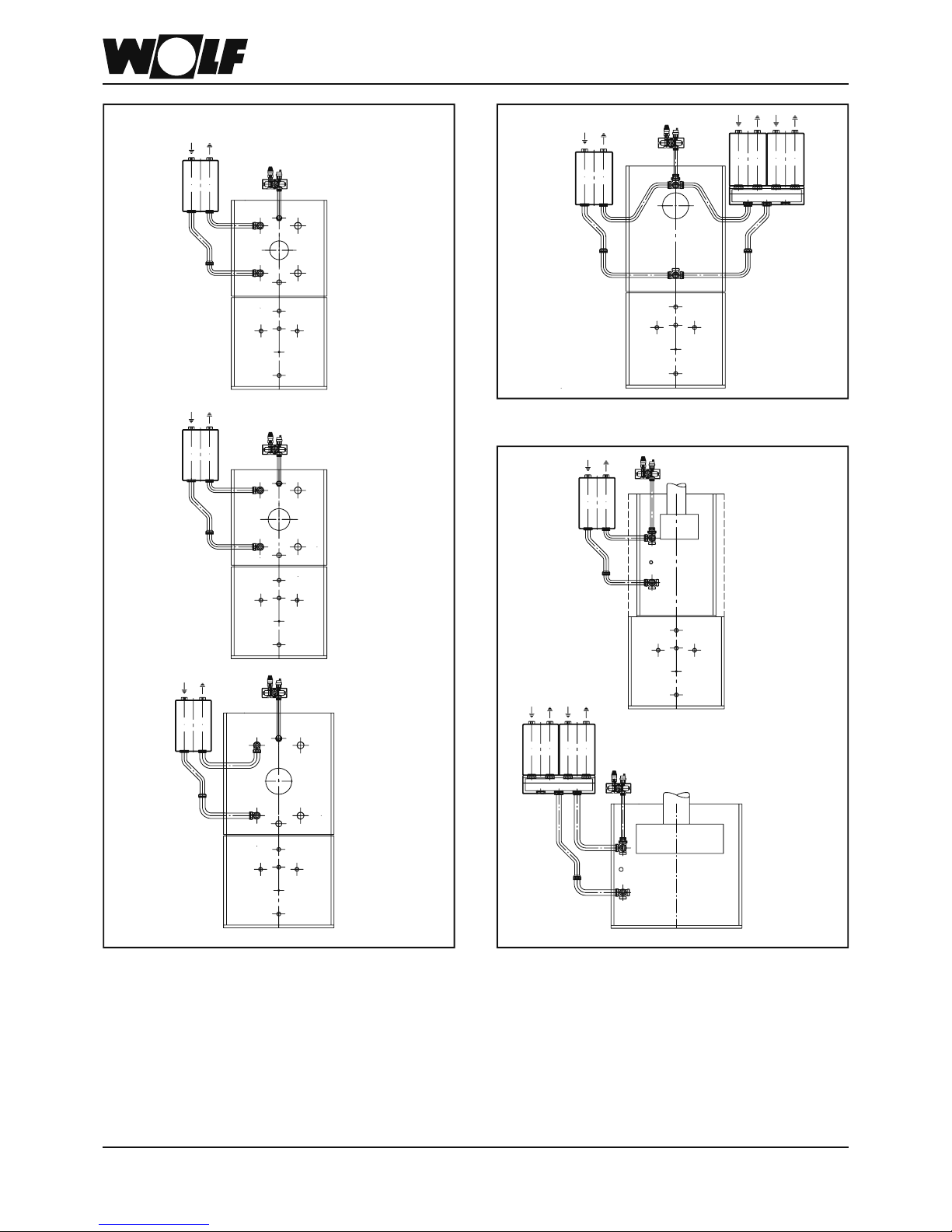
Montage:
• Alle möglichen Montagepositionen für die Verrohrungssets
sind auf den Seiten 9 - 11 dargestellt.
• Vor- und Rücklaufrohr muß beim Gußkessel in den Kesselkörper fest und gleich tief eingeschraubt sein (-> mit Zollstock
zum Kesselanschlag hin messen)
• Bei allen Verschraubungen müssen die beiliegenden Flachdichtungen eingelegt werden
• Kreuz- bzw. T-Stücke handfest anschrauben.
Ausrichtung der Abgänge bei Vor- und Rücklauf:
-> Zeichnungen beachten!
• Vorlaufrohr und unteres Rücklaufrohr handfest anschrauben.
CNK 17 / 20 / 25: Das L-Rohr mit dem längeren
Schenkel wird am Vorlauf
montiert
CNK 32 / 40: Das L-Rohr mit dem längeren
Schenkel wird am Rücklauf
montiert
CNK 50 / 63: Das U-Rohr wird am Vorlauf
montiert
CNG 10 – 35 / FNG 10 – 41: beide L-Rohre sind identisch
• Rohre waagerecht ausrichten und Kreuzstücke am Kessel
festziehen.
• Oberes Rücklaufrohr mit unterem Rücklaufrohr handfest
veschrauben und in gewünschte Position drehen.
• Verrohrungsset bzw. Verteiler aufsetzen und handfest verschrauben.
• Vorlauf- und Rücklaufrohr an den Kreuzstücken festziehen.
• Verrohrungsset bzw. Verteiler vor- und rücklaufseitig festziehen.
• Verschraubung zwischen oberem und unteren Rücklaufrohr
festziehen.
• Verrohrungsset bzw. Verteiler nochmal ausrichten und alle
Verschraubungen nachziehen.
Lieferumfang:
• 1 Vorlaufrohr
• 2 Rücklaufrohre
• 2 Kreuz- bzw. T-Stücke (nicht im Erweiterungsset CHK
enthalten)
• Verschlußkappen 1 ½”
• Flachdichtungen 1 ½”
• Montageanleitung
Montageanleitung
Anschlußset für Verrohrungsset
Übersicht der Anschlußsets zur Montage eines Verrohrungssets bzw. Verteilers:
CNK 17 - 40 CNK 50 / 63 CHK 22 - 60 CNG 10 - 35 FNG 10 – 41 CNG 48 FNG 57
Art.-Nr. Grundset 24 10 092 24 10 095 24 10 093 24 10 094 24 10 094 24 10 097 24 10 097
Art.-Nr. Erweiterungsset 24 10 092 24 10 095 24 10 098 - - - -
Page 4

4
3043663_0203
Installation:
• Possible installation positions for pipework assemblies are
shown on pages 9 - 11.
• Flow and return pipe of cast iron boilers have to be fi tted tight
to the boiler body and project the rear surface at identical
dimensions (-> check dimensions to boiler rear by means
of folding meter).
• For any screwed fi tting use enclosed fl at seals.
• Cross or T-pieces to be hand-screwed.
Alignement of connections for fl ow and return:y
-> see drawings!
• Flow tube and inferior return tube have to be hand-screwed.
CNK 17 / 20 / 25: The L-shape tube with the longer
side has to be fi tted to the fl ow
CNK 32 / 40: The L-shape tube with the lon-
ger side has to be fi tted to the
return
CNK 50 / 63: The U-shape tube has to be
fi tted to the fl ow
CNG 10 – 35 / FNG 10 – 41: both L-shape tubes are identical
• Align tubes horizontally and screw cross pieces tight to
boiler.
• Superior return tube to be fi tted to inferior return tube (hand-
screwed) and to be turned to required position.
• Pipework assembly or header to be fi tted and hand screwed.
• Screw tight fl ow and return tubes on cross pieces.
• Screw tight fl ow and return of pipework assembly or header.
• Fasten screwed fi tting between superior and inferior return tube.
• Pipework assembly or header to be aligned once more and
all screwed fi ttings to be fastened.
Scope of supply:
• 1 Flow tube
• 2 return tubes
• 2 Cross or T-pieces (not enclosed in extension kit for CHK)
• Sealing caps 1 ½”
• Flat seals 1 ½”
• Installation instructions
Installation instructions
Connection kit for pipework assembly
Survey of connection kits for the installation of a pipework assembly or header:
CNK 17 - 40 CNK 50 / 63 CHK 22 - 60 CNG 10 - 35 FNG 10 – 41 CNG 48 FNG 57
Art.-No. basic kit 24 10 092 24 10 095 24 10 093 24 10 094 24 10 094 24 10 097 24 10 097
Art.-No. extension kit 24 10 092 24 10 095 24 10 098 - - - -
Page 5

5
3043663_0203
Montage:
• Tous les montages possibles des groupes de raccordement
sont présentés en pages 9 à 11.
• Sur les chaudières en fonte, les tuyauteries départ et retour
doivent être solidement vissées au corps de chauffe .
• Mettre les joints plats fournis sur chaque raccord union.
• Visser solidement les raccords en X ou les Tés.
Alignement des sorties sur les tuyauteries départ et retour:
-> se conformer aux schémas !
• Visser solidement la tuyauterie départ et la tuyauterie retour
inférieure.
CNK 17 / 20 / 25: Le tuyau en L avec la partie
coudée la plus longue est monté
sur le départ.
CNK 32 / 40: Le tuyau en L avec la partie
coudée la plus longue est monté
sur le retour.
CNK 50 / 63: Le tuyau en U est monté sur le
départ.
CNG 10 – 35 / FNG 10 – 41: Les 2 tuyaux sont identiques.
• Aligner horizontalement les tuyaux et fi xer les raccords en
X sur la chaudière.
• Visser le tuyau retour supérieur avec le tuyau retour inférieur
et les faire pivoter dans la position souhaitée.
• Mettre en place le groupe de raccordement et le visser
solidement.
• Fixer les tuyauteries départ et retour aux raccords en X.
• Fixer le groupe de raccordement aux sorties latérales départ
et retour.
• Serrer les écrous entre la tuyauterie retour supérieure et la
tuyauterie retour inférieure.
• Réaligner le groupe de raccordement et resserer solidement
tous les écrous.
Comprenant:
• 1 Tuyau Départ
• 2 Tuyaux Retour
• 2 Raccords en X ou Tés (non inclus avec le kit
d’entension pour CHK)
• Robinets boisseaux 1 ½”
• Joints plats 1 ½”
• Notice de Montage
Notice de Montage
Set de connexions groupe de raccordement
vue d’ensemble du set de connexions pour montage d’un groupe de raccordement chauffage
CNK 17 - 40 CNK 50 / 63 CHK 22 - 60 CNG 10 - 35 FNG 10 – 41 CNG 48 FNG 57
N°Art.kit de base 24 10 092 24 10 095 24 10 093 24 10 094 24 10 094 24 10 097 24 10 097
N°Art.kit d’extension 24 10 092 24 10 095 24 10 098 - - - -
Page 6

6
3043663_0203
Montage:
• Alle mogelijke montageposities voor de buizensets worden
op bladzijde 14 - 16 voorgesteld.
• Bij de gietijzeren ketel moeten de voor- en terugloopleiding
stevig en even diep in het ketellichaam geschroefd worden
(-> met een duimstok tot aan de ketelaanslag meten).
• Bij alle schroefverbindingen moeten de bijgevoegde vlakdichtingen ingevoegd worden.
• Schroef de kruis- resp. T-stukken stevig vast.
Uitrichting van de uitgangen bij voor- en terugloop:
-> Houd u aan de tekeningen!
• Schroef de voorloopleiding en de onderste terugloopleiding
stevig vast.
CNK 17 / 20 / 25: De L-buis met het langere
been wordt op de voorloop
gemonteerd
CNK 32 / 40: De L-buis met het langere
been wordt op de terugloop
gemonteerd
CNK 50 / 63: De U-buis wordt op de voorloop
gemonteerd
CNG 10 – 35 / FNG 10 – 41: beide L-buizen zijn identiek
• Richt de buizen horizontaal uit en draai de kruisstukken aan
de ketel vast.
• Schroef de bovenste terugloopleiding stevig met de onderste
terugloopleiding vast en draai ze in de gewenste positie.
• Zet er de buizenset resp. verdeler op en schroef stevig vast.
• Draai de voor- en terugloopleiding aan de kruisstukken vast.
• Draai de buizenset resp. verdeler aan de kant van de vooren terugloop vast.
• Draai de schroefverbinding tussen de bovenste en onderste
terugloopleiding vast.
• Richt de buizenset resp. verdeler nogmaals uit en draai alle
schroefverbindingen vaster aan.
Leveringsomvang:
• 1 voorloopleiding
• 2 terugloopleidingen
• 2 kruis- resp. T-stukken (niet in de uitbreidingsset CHK
inbegrepen)
• Afsluitkappen 1 ½”
• Vlakdichtingen 1 ½”
• Montagehandleiding
Montagehandleiding
Aansluitset voor buizenset
Overzicht van de aansluitsets voor de montage van een buizenset resp. verdeler:
CNK 17 - 40 CNK 50 / 63 CHK 22 - 60 CNG 10 - 35 FNG 10 – 41 CNG 48 FNG 57
Art.nr. basisset 24 10 092 24 10 095 24 10 093 24 10 094 24 10 094 24 10 097 24 10 097
Art.nr. uitbr.set 24 10 092 24 10 095 24 10 098 - - - -
Page 7

7
3043663_0203
Montaggio:
• Le posizioni di montaggio possibili per i gruppi di collegamento sono mostrate a pag. 9-11.
• La tubazione di mandata e ritorno per le caldaie in ghisa deve
essere avvitata a tenuta nel corpo caldaia (-> mit Zollstock
zum kesselanschlag hin messen)
• In tutti i raccordi a vite devono essere inserite le apposite
guarnizioni piatte.
• I raccordi a croce ed a T devono devono essere avvitati
saldamente.
Per l‘allineamento degli scarichi di mandata e ritorno pre-
stare attenzione alle fi gure!
• Avvitare saldamente il tubo di mandata ed il tubo di ritorno
sottostante.
CNK 17 / 20 / 25: Il tubo a L con il lato più lungo
viene montato sulla mandata.
CNK 32 / 40: Il tubo a L con il lato più lungo
viene montato sulla mandata.
CNK 50 / 63: Il tubo a U viene montato sulla
mandata.
CNG 10 – 35 / FNG 10 – 41: i due tubi a L sono identici.
• Posizionare i tubi orizzontalmente e fi ssare i raccordi a croce
alla caldaia.
• Avvitare saldamente il tubo di ritorno superiore a quello
inferiore e girare nella posizione desiderata.
• Posizionare il gruppo di collegamento ed il collettore ed
avvitare saldamente.
• Fissare il tubo di mandata e ritorno ai raccordi a croce.
• Fissare il gruppo di collegamento ed il collettore sul lato
mandata e ritorno.
• Fissare il raccordo tra il tubo di ritorno superiore e quello
inferiore.
• Allineare nuovamente il gruppo di collegamento ed il collettore
e stringere tutti i raccordi a vite.
Composto da:
• 1 tubo di mandata
• 2 tubi di ritorno
• 2 raccordi a croce o a T (non compresi nel gruppo di espansione CHK)
• Cappucci 1 ½”
• Guarnizioni piatte 1 ½”
• Istruzioni di montaggio
Istruzioni di montaggio
Gruppo di collegamento per le tubazioni
CNK 17 - 40 CNK 50 / 63 CHK 22 - 60 CNG 10 - 35 FNG 10 – 41 CNG 48 FNG 57
Art. Gruppo di collegam. 24 10 092 24 10 095 24 10 093 24 10 094 24 10 094 24 10 097 24 10 097
Art. Gruppo di espansione 24 10 092 24 10 095 24 10 098 - - - -
Prospetto dei gruppi di collegamento per il montaggio delle tubazioni e del collettore:
Page 8

8
3043663_0203
Montaje:
• Todas las posibilidades de montaje estan refl ejadas en las
paginas 9 - 11 .
• La tuberia de impulsión y retorno tienen que enroscarse de
igualmanera ( fuerte y misma longitud ) en el cuerpo de fundición de la caldera (-> medir desde el tope del cuerpo)
• En todas las uniones se ha de montar la junta suministrada.
• Apretar las piezas en t y/o en cruz con la mano
Tener en cuenta las posiciones de conexión de imp./ ret.
-> Ver dibujo!
• Apretar con la mano tubo de impulsión y retorno.
CNK 17 / 20 / 25: El tubo en L se conecta con la
parte mas larga a l la impulsión
CNK 32 / 40: El tubo en L se conecta con la
parte mas mas larga al retorno
CNK 50 / 63: El tubo en U se monta en la
impulsión
CNG 10 – 35 / FNG 10 – 41: los dos tubos en L son identicos
• Posicionar a nivel los tubos y apretar las piezas en T y en
cruz.
• Apretar a mano la tuberias de retorno superior e inferior y
girar en la posición adecuada.
• Posicionar el colector o conjunto de distribución y apretar
a mano .
• Apretar el tubo de impulsión y retorno a las piezas en
cruz.
• Apretar conjunto de distribución o colector a impulsión y
retorno.
• Apretar las conexiones entre retorno superior e inferior.
• Volver a nivelar colector o conjunto de distribución y apretar
de nuevo todas las uniones.
Suministro:
• 1 Tubo de impulsión
• 2 Tubo de retorno
• 2 Pieza en cruz y/o T (no incluidas con juego de ampliación de la CHK )
• Cierre 1 ½”
• Junta plana 1 ½”
• Instrucciones de montaje
Instrucciones de montaje
Kit de conexiones para conjunto de distribución
Tabla de kits de conexiones para conjuntos de distribuciónpara el montajed de un conjunto o colector:
CNK 17 - 40 CNK 50 / 63 CHK 22 - 60 CNG 10 - 35 FNG 10 – 41 CNG 48 FNG 57
Nº kit básico 24 10 092 24 10 095 24 10 093 24 10 094 24 10 094 24 10 097 24 10 097
Nº.art. juego ampliación 24 10 092 24 10 095 24 10 098 - - - -
Page 9

9
3043663_0203
TNU / TNK ; CNU / CNK
* Höhe der Füße/Fußschrauben 20mm ±10mm beachten! * Hoogte van de voetstukken/stelschroeven 20 mm ± 10 mm in acht nemen!
* Height of feet/levelling screws 20mm ±10mm to be taken into account! * Fare attenzione all‘altezza dei piedini/viti di appoggio 20mm ±10mm!
* Prendre en considération une hauteur de pieds chaudière de 20mm ±10mm! * Tener en cuenta la altura de los pies de nivelación 20mm ±10mm !
M*
L*
355125
355
K*
J*
355
125
I*
355
H*
Höhenmaße / with triple header / Hauteurs / Dimensioni verticali /
Afmetingen in de hoogte
125
750
D
G
2
G
1
178
58
mit 3-fach Verteilerbalken / with triple header / avec collecteur 3 circuits / con collettori tripli / met drievoudige verdeelbalken
D
F
2
F
1
178
58
125
500
A
E
178
58
125
500
mit 2-fach Verteilerbalken / with double header / avec collecteur 2 circuits / con collettori doppi / met tweevoudige verdeelbalken
C
1
D
125
178
58
250
C
2
A
178
58
125
250
B
ohne Verteilerbalken / without header / sans collecteur / senza collettori circuito riscaldamento / zonder verdeelbalken
TopOne TNU/TNK ComfortLine CNU/CNK
17 20 25 17 20 25 32 40 50 63
A mm 184 184 184 169 169 169 169 169 170 170
B mm 318 318 318 338 338 338 338 338 333 333
C1/C2 mm 188/313 188/313 188/313 173/298 173/298 173/298 173/298 173/298 174/299 174/299
D mm 250 250 250 270 270 270 270 270 265 265
E mm 505 505 505 525 525 525 525 525 520 520
F1/F2 mm 251/501 251/501 251/501 236/486 236/486 236/486 236/486 236/486 237/487 237/487
G1/G2 mm 376/626 376/626 376/626 361/611 361/611 361/611 361/611 361/611 362/612 362/612
H mm 1661 1661 1661 1573 1573 1573 1573 1573 1561 1561
I mm 1786 1786 1786 1698 1698 1698 1698 1698 1686 1686
J mm 1290 1290 1290 1227 1227 1227 1227 1227 1215 1215
K mm 1025 1025 1025 937 937 937 937 937 925 925
L mm 1415 1415 1415 1352 1352 1352 1352 1352 1340 1340
M mm 1150 1150 1150 1062 1062 1062 1062 1062 1050 1050
Page 10

10
3043663_0203
TOK / THU / THK ; CHU / CHK
* Höhe der Füße/Fußschrauben 20mm ±10mm beachten! * Hoogte van de voetstukken/stelschroeven 20 mm ± 10 mm in acht nemen!
* Height of feet/levelling screws 20mm ±10mm to be taken into account! * Fare attenzione all‘altezza dei piedini/viti di appoggio 20mm ±10mm!
* Prendre en considération une hauteur de pieds chaudière de 20mm ±10mm! * Tener en cuenta la altura de los pies de nivelación 20mm ±10mm !
M*
L*
355125
355
K*
J*
355
125
I*
355
H*
Höhenmaße / with triple header / Hauteurs / Dimensioni verticali /
Afmetingen in de hoogte
125
750
D
G
2
G
1
178
58
mit 3-fach Verteilerbalken / with triple header / avec collecteur 3 circuits / con collettori tripli / met drievoudige verdeelbalken
F
2
F
1
178
58
125
500
D
A
178
58
125
500
E
mit 2-fach Verteilerbalken / with double header / avec collecteur 2 circuits / con collettori doppi / met tweevoudige verdeelbalken
C
1
C
2
125
178
58
250
D
A
178
58
125
250
B
ohne Verteilerbalken / without header / sans collecteur / senza collettori circuito riscaldamento / zonder verdeelbalken
TOK TopOne THU/THK ComfortLine CHU/CHK
22 22 29 22 29 37 45 60
A mm 177 297 297 177 177 177 177 177
B mm 318 318 318 338 338 338 338 338
C1/C2 mm 181/306 301/313 301/313 181/306 181/306 181/306 181/306 181/306
D mm 250 250 250 270 270 270 270 270
E mm 505 505 505 525 525 525 525 525
F1/F2 mm 244/494 364/614 364/614 244/494 244/494 244/494 244/494 244/494
G1/G2 mm 369/619 489/739 489/739 369/619 369/619 369/619 369/619 369/619
H mm - 1565 1565 1566 1566 1566 1566 1566
I mm - 1690 1690 1691 1691 1691 1691 1691
J mm 1344 1194 1194 1220 1220 1220 1220 1220
K mm 929 929 929 930 930 930 930 930
L mm 1469 1319 1319 1345 1345 1345 1345 1345
M mm 1054 1054 1054 1055 1055 1055 1055 1055
Page 11

11
3043663_0203
TNG; CNG; FNG
* Höhe der Füße/Fußschrauben 20mm ±10mm beachten! * Hoogte van de voetstukken/stelschroeven 20 mm ± 10 mm in acht nemen!
* Height of feet/levelling screws 20mm ±10mm to be taken into account! * Fare attenzione all‘altezza dei piedini/viti di appoggio 20mm ±10mm!
* Prendre en considération une hauteur de pieds chaudière de 20mm ±10mm! * Tener en cuenta la altura de los pies de nivelación 20mm ±10mm !
M*
L*
355125
355
K*
J*
355
125
I*
355
H*
Höhenmaße / with triple header / Hauteurs / Dimensioni verticali /
Afmetingen in de hoogte
178
58
G
2
G
1
125
750
D
mit 3-fach Verteilerbalken / with triple header / avec collecteur 3 circuits / con collettori tripli / met drievoudige verdeelbalken
178
58
F
2
F
1
125
500
D
A
178
58
125
500
E
mit 2-fach Verteilerbalken / with double header / avec collecteur 2 circuits / con collettori doppi / met tweevoudige verdeelbalken
C
2
C
1
125
178
58
250
D
B
178
A
58
125
250
ohne Verteilerbalken / without header / sans collecteur / senza collettori circuito riscaldamento / zonder verdeelbalken
Top One Comfort Line / Function Line
TNG-17 TNG-23 TNG-29 CNG-10
FNG-10
CNG-17
FNG-17-FNG-21
CNG-23
FNG-26
CNG-29
FNG-34
CNG-35
FNG-41
CNG-48
FNG-57
A mm 260 260 260 255 255 255 255 255 255 257
B mm 360 402 444 399 399 399 399 427 427 421
C1/C2 mm 264/353 264/353 264/353 259/348 259/348 259/348 259/348 259/348 259/348 261/350
D mm 292 334 376 331 331 331 331 359 359 353
E mm 547 589 631 586 586 586 586 614 614 608
F1/F2 mm 327/577 327/577 327/577 322/572 322/572 322/572 322/572 322/572 322/572 324/574
G1/G2 mm 452/702 452/702 452/702 477/697 477/697 477/697 477/697 477/697 477/697 449/699
H mm 1675 1675 1675 - 1585 1585 1585 1585 1585 -
I mm 1800 1800 1800 - 1710 1710 1710 1710 1710 -
J mm 1304 1304 1304 1239 1239 1239 1239 1239 1239 1549
K mm 1039 1039 1039 949 949 949 949 949 949 1259
L mm 1429 1429 1429 1364 1364 1364 1364 1364 1364 1674
M mm 1164 1164 1164 1074 1074 1074 1074 1074 1074 1384
 Loading...