

Page 1
Document no.: 3063527_201308 Subject to technical modications. GB
Wolf GmbH · Postfach 1380 · D-84048 Mainburg · Tel. +49 (0)8751/74-0 · Fax +49 (0)8751/741600 · Internet: www.wolf-heiztechnik.de
Operating instructions
Control unit - CGL
20.0 °C
Friday
31/10/08
12 : 16
Zone 1
Page 2

3063527_2013082
Table of contents
Safety instructions, service / repair .............................................................................. 4
Standards and regulations ........................................................................................... 5
Unit description / disposaland recycling ..................................................................... 6
Zoning .............................................................................................................................. 7
Installation as an external remote control ................................................................... 8
Electrical connection ..................................................................................................... 8
BML overview ................................................................................................................. 9
Control level 1 .......................................................................................................... 10-13
L.h. rotary selector, program selection ....................................................................... 10
R.h. rotary selector ..................................................................................................... 10
Program selection ................................................................................................. 10-11
Automatic mode ................................................................................................... 10
Manual mode.........................................................................................................11
Ventilation mode ....................................................................................................11
Standby mode .......................................................................................................11
Info key ................................................................................................................. 11-12
Temperature selection key ......................................................................................... 12
Speed adjustment key ............................................................................................... 12
Display explained ......................................................................................................... 13
Control level 2 .......................................................................................................... 14-24
Main menu overview .................................................................................................. 14
Displays ..................................................................................................................... 15
Acknowledge faults .................................................................................................... 15
Basic settings ............................................................................................................. 16
Language ............................................................................................................. 17
Date ...................................................................................................................... 17
Time ..................................................................................................................... 17
Automatic summertime......................................................................................... 18
Key lock ................................................................................................................ 18
Zone Z1 ................................................................................................................ 19
Day temperature................................................................................................... 19
Economy temperature for heating ........................................................................ 19
Backup temperature for heating ........................................................................... 19
Speed adjustment ................................................................................................ 20
Setback mode program ........................................................................................ 20
Supply air minimum limit ...................................................................................... 20
Enable night ventilation ........................................................................................ 21
Time program ............................................................................................................. 21
Switching times, factory setting ............................................................................ 22
Holiday program ......................................................................................................... 23
Specialist .................................................................................................................... 24
Page 3

3063527_201308
3
Control level 3 .......................................................................................................... 24-32
Code scan .................................................................................................................. 24
New conguration / Sensor check ............................................................................. 24
Zone designat ............................................................................................................ 24
Ventilation unit parameters ........................................................................................ 25
Relay test ................................................................................................................... 25
Zone reset .................................................................................................................. 25
Setting parameters ....................................................................................................... 26
Specialist parameter list - overview ...................................................................... 26-27
Parameters / function description ......................................................................... 28-32
Master reset / standard functions .......................................................................... 33-34
Motor protection ......................................................................................................... 33
Room frost protection ................................................................................................. 33
Central heating backup mode .................................................................................... 34
Supply air minimum limit for heating .......................................................................... 34
Filter contamination fault trigger ................................................................................. 34
Active lter monitor .................................................................................................... 34
Fan run-on time .......................................................................................................... 34
External ON/OFF ....................................................................................................... 34
Additional functions ................................................................................................ 34-36
Room/supply air cascade control ............................................................................... 35
Night ventilation ......................................................................................................... 35
Preheater coil, HR ice guard ...................................................................................... 36
Condensate overow ................................................................................................. 36
Summer shutdown ..................................................................................................... 36
Heat recovery ............................................................................................................. 36
HR ice guard .............................................................................................................. 36
Fire alarm ................................................................................................................... 36
CO2 control ..................................................................................................... 31, 32, 37
Sensor resistances....................................................................................................... 37
Specication ................................................................................................................. 38
System conguration ................................................................................................... 39
Terminal assignments .................................................................................................. 40
Fault messages........................................................................................................ 41-43
Wiring diagram ........................................................................................................ 44-47
Menu structure ......................................................................................................... 48-51
Table of contents
Page 4
3063527_2013084
Safety instructions
The following symbols are used in this instruction manual. This
important information concerns personal as well as operational
safety.
"Safety instructions" must be complied with to the letter, to prevent
risks and injuries to individuals and material losses on the appliance.
Danger through 'live' electrical components!
Please note: Turn off the ON/OFF switch before removing the
casing.
Never touch electrical components or contacts when the ON/OFF
switch is in the ON position. This would lead to a risk of electrocution
that may lead to injury or death.
"Note" indicates technical instructions that must be observed to
prevent material losses and equipment malfunctions.
Even when the unit has been shut down, voltage will still be present
at terminals and connections of the EC fans. This means there is
a risk of electric shock that could result in injury or death.
Never touch the EC fans until ve minutes after disconnecting the
power across all poles have elapsed.
Please note
Safety instructions
Service / Repair
- Regularly check the perfect function of all electrical equipment.
- Only qualied personnel may remove faults or repair damage.
- Only replace faulty components or equipment with original Wolf
spare parts.
- Observe specied electrical fuse ratings (see specication).
Any damage or loss resulting from technical modications to Wolf
control units is excluded from our warranty.
Please note
Service / Repair
Page 5
3063527_201308
5
Standards / Regulations
- According to DIN EN 50110-1, only qualied electricians may
carry out the installation and commissioning of the ventilation
control unit and connected accessories.
- Observe all regulations stipulated by your local power supply
utility and all VDE or local regulations.
- DIN VDE 0100 regulations regarding the installation of high
voltage systems up to 1000 V
- DIN VDE 0105-100 Operation of electrical plants
- Use exclusively original Wolf accessories (electric heater coil,
condensate pump, servomotors, etc.), otherwise the Wolf
warranty will be void.
Only use cables that meet local wiring regulations with regard to
voltage, current, insulation material, load etc. Always t an earth
conductor.
Power supply:
An externally accessible, omnipolar isolator must be installed
with the appliance. Power cable, external: 3 x 2.5 mm².
Fuse/MCB protection: 230 V/16 A.
RCD
Only AC/DC-sensitive RCDs of type B with 300 mA rating are
permissible.
Connect the power cable and accessories in accordance with
the wiring diagram provided.
A high leakage current can be expected due to the EC
motors. Ensure that a secure earth connection is in place
before connecting the power supply and commencing
commissioning.
For Austria, the ÖVE regulations and local building regulations
apply.
Installation /
Commissioning
Warnings - Removing, bypassing or disabling of safety and monitoring
equipment is not permissible.
- The system must only be operated if it is in perfect technical
condition. Immediately have any faults and damage that may
impact on safety removed.
The appliance and control unit accessories comply with the
following regulations:
EC Directives
- 2006/95/EC Low Voltage Directive
- 2004/108/EC EMC Directive
EN Standards
- EN 60730-1 Automatic electrical controls for household and
similar use
- EN 60730-2-11 Particular requirements for temperature
sensing controls
- EN 61000-6-2 EMC Immunity for industrial environments
- EN 61000-6-3 EMC Emission standard for residential
environments
Standards / Directives
Page 6

3063527_2013086
The control panel is designed for regulating large area ventilation
units with variable speed EC motors.
Other functions
- HR control 0 - 10 V
- CO2-based fan speed matching
- Electric reheater coil: variable control 0 - 10 V
- Room / supply air cascade control or supply air control
- Night ventilation
- Electric preheater coil:
Switching ON/OFF by outside temperature
The control unit can be operated with the programming module
for ventilation units (BML programming module, material number
2744634). The BML programming module can also be used to
program switching times, to modify parameters and to display
fault messages.
The control unit has an eBUS interface and can therefore be fully
integrated into the Wolf control system.
There can only be one BML in any one system (eBUS).
Up to 7 CGL units can be operated with one programming unit.
Please note
Unit description
Unit description
Observe the following information regarding the disposal of faulty
system components or the system at the end of its service life:
Dispose of all components in accordance with applicable
regulations, i.e. separate material groups correctly. The aim should
be the maximum possible amount of basic materials recycled and
the lowest possible environmental impact.
Never dispose of electrical or electronic scrap through household
waste, but recycle it appropriately.
Generally, dispose of materials in the most environmentally
responsible manner according to environmental, recycling and
disposal standards.
Disposal and recycling
The ventilation unit is designed for air intake temperatures between
-20 °C and +40 °C. Only store the ventilation unit in dry conditions
at an ambient temperature between -25 °C and +55 °C.
Wolf CGL ventilation units are designed to heat and lter normal
air. The use of these units in wet rooms or rooms with explosive
atmospheres is not permissible. Handling very dusty or aggressive
media is not permissible.
Any on-site modication or unintended use of the unit is not
permissible and Wolf GmbH accepts no liability for any damage
caused as a result.
Intended use
Page 7
3063527_201308
7
Zoning
Zoning
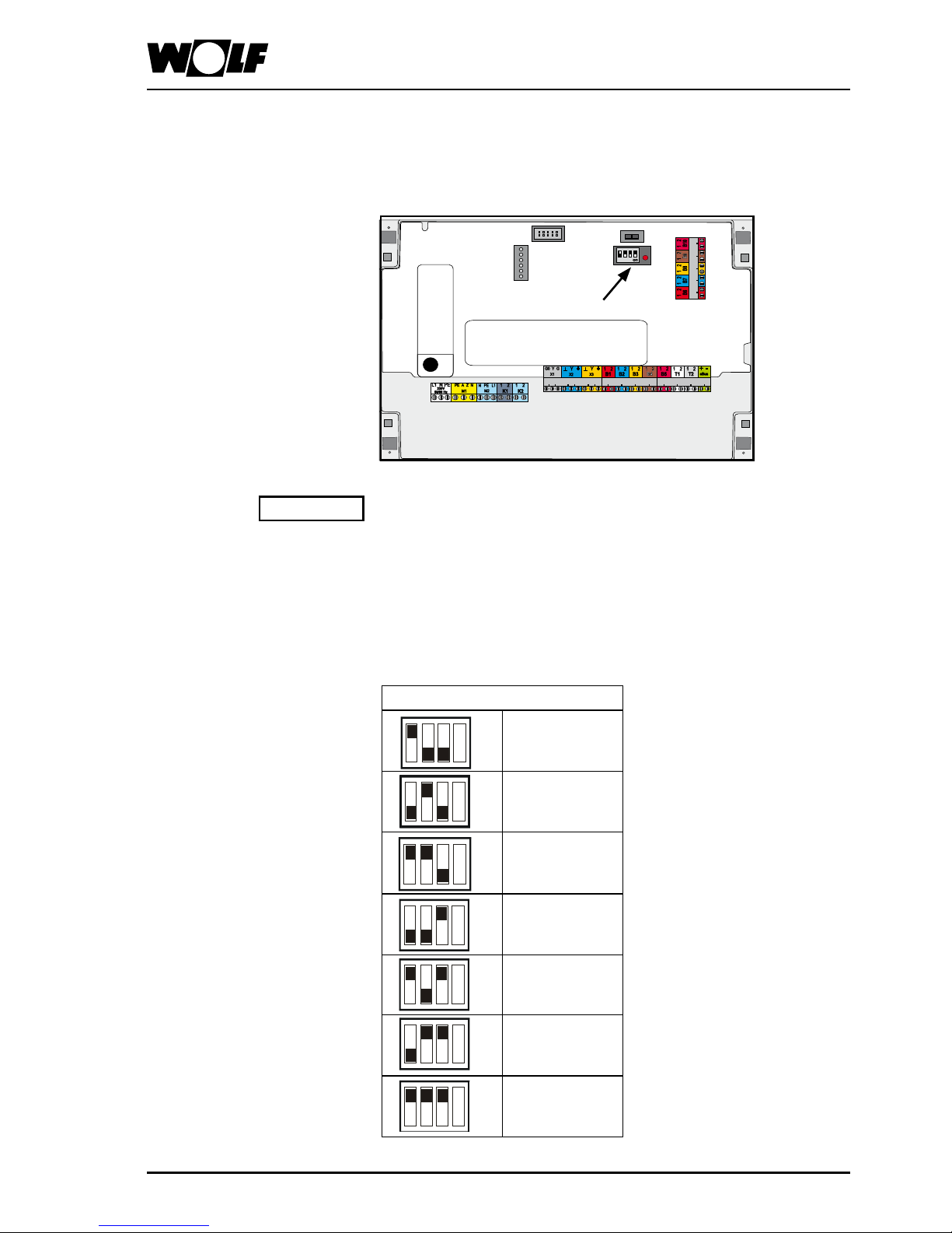
When more than one CGL is controlled with one programming unit,
the zone for each appliance must be set using the DIP switches
on the control PCB (in the control panel).
If only one zone is to be connected, the following chapter can
be skipped.
Multiple zones in one
system
The three switches on the left hand side of the 4-position DIP switch
can be used to assign the ventilation unit to a zone.
Up to seven zones are possible in one system.
Zone setting
Zone 1
Zone 2
Zone 3
Zone 4
Zone 5
Zone 6
Zone 7
Fig.:
DIP switches on the
control PCB
DIP switches
Control PCB
X1
Never pull out the coding card X1, otherwise malfunctions may
result.
Please note
Page 8
3063527_2013088
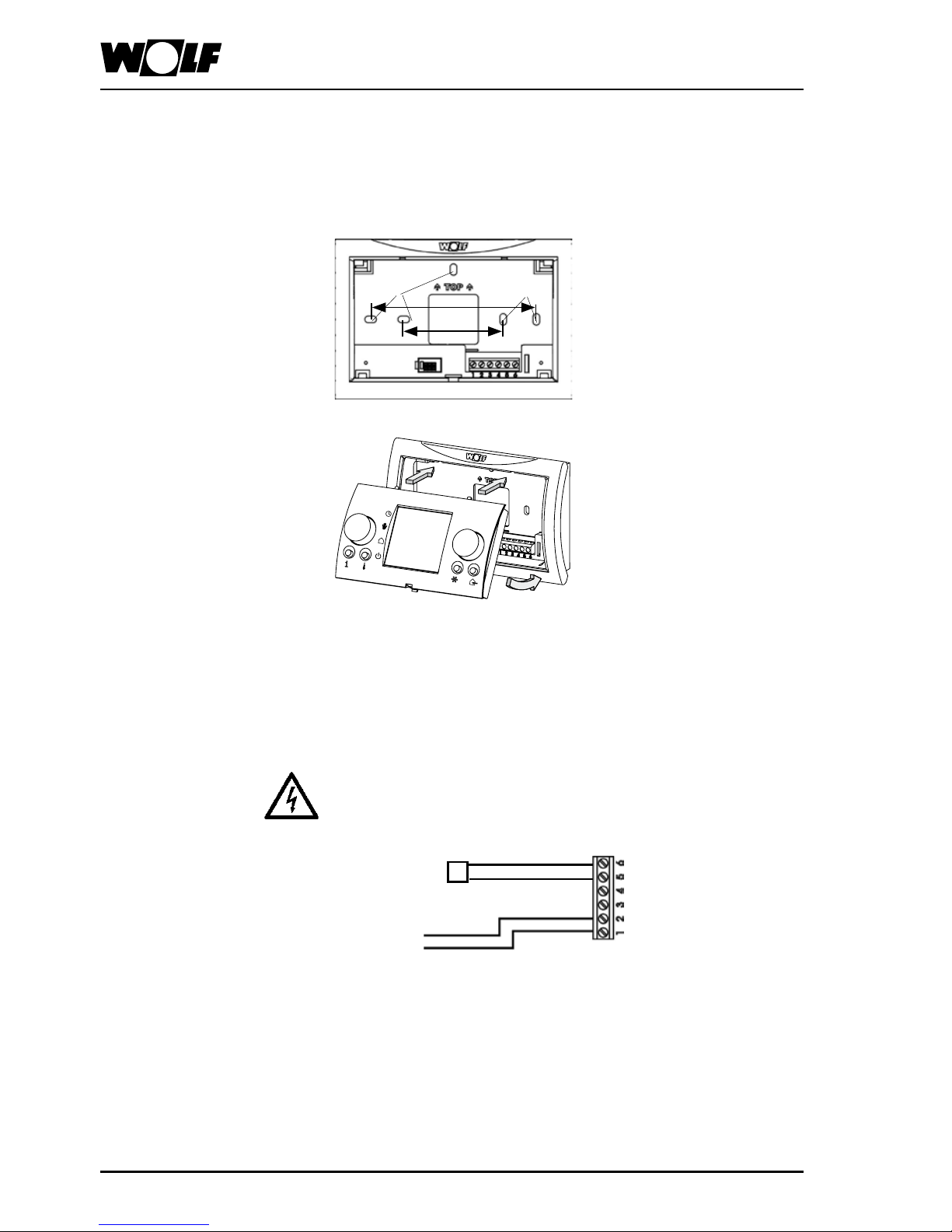
Installation as an external remote
control
Wall mounting base
installation
- Remove the wall mounting base from its packaging.
- Secure the wall mounting base on a ush-mounting box
(Ø 55 mm) or directly on the wall.
Wall mounting base
Fixing holes
Fixing holes
Installation of BML on wall mounting base
Wall mounting base
Mat. no. 2744275
60
100
Electrical connection of
remote control
- The electrical connection must be carried out only by a qualied
electrician.
- Never route sensor leads alongside mains power cables.
- Use the repair switch to switch off the power supply
- Wire the wall mounting base with a four-core cable (minimum
cross-section 0.5 mm²) in accordance with the diagram
eBUS
Terminal strip
Wall mounting base
+ -
+ -
Recommended cables
and
minimum cable
cross-sections:
H05VV-F 3 x 2.5 mm² power cable (230 V)
H05VV-F 4 x 1.0 mm² Open/Close servomotor 230 V
H05VV-F 2 x 0.5 mm² BUS cable (<400 m length)
Fuse/MCB protection: Power supply 230 V 1 x 16 A
ϑ
Outside temperature sensor
Page 9
3063527_201308
9
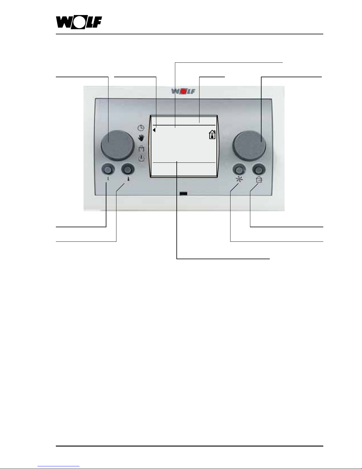
BML overview
L.h. rotary selector R.h. rotary selector
Info key
Temperature
adjustment
Speed adjustment
DisplayStatus indicator
Minimum fresh air proportion
(no function)
20.0 °C
Friday
31/10/08
12 : 16
Zone 1
Room temperature / extract air temperature
Time alternating with
outside temperature
Page 10
3063527_20130810
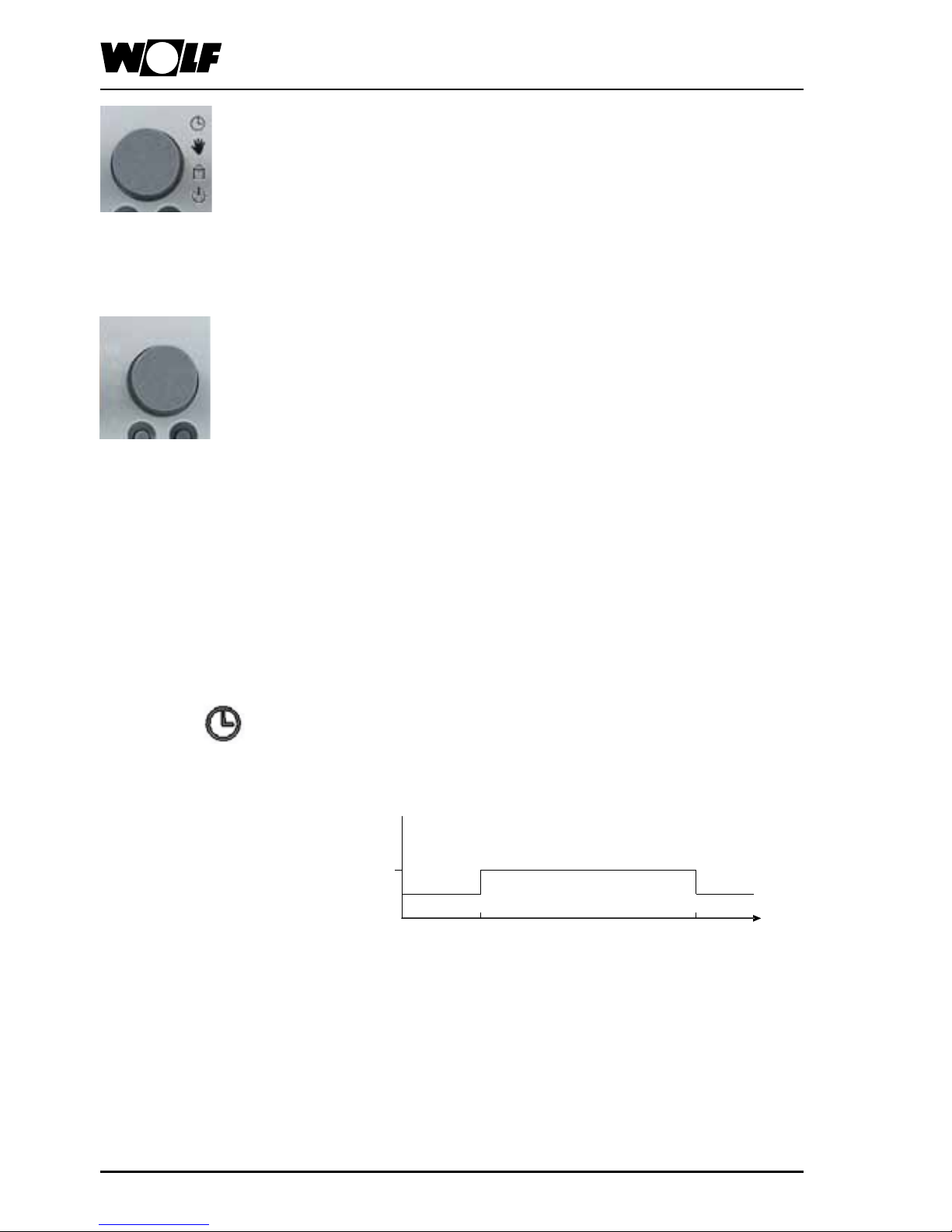
Program selection
You can select the programs listed below by turning the l.h. rotary
selector.
The arrow on the l.h. edge of the display points to the selected
program.
R.h. rotary selector
The right hand rotary selector is used for all programming steps.
Turning the rotary selector enables you to select the required
menu item.
Pressing the r.h. rotary selector conrms the programming step.
L.h. rotary selector, program selection
This rotary selector enables the program to be selected. The rotary
selector can be rotated indenitely, without an end stop. You will
feel it click into each position as it rotates. The selected function
is indicated by an arrow in the display.
Control level 1
Automatic mode
Ventilation according to a time switch program. Call-up of HR,
reheater and fan according to demand.
As shown in the diagram, you can preselect the operating mode
via the time program when the system has been switched off.
06:00
22:00
On
Off
„Day mode”
Time
Setback mode program
Selection:
- Economy operation
- Backup mode (factory setting)
- Standby
- Summer ventilation
Backup mode Backup mode
07:00
14:00
Page 11
3063527_201308
11
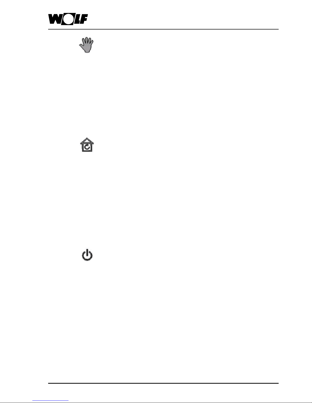
Control level 1
Manual mode
The ventilation time program is inactive. With this setting, ventilation
is enabled 24 hours a day. The set value from day mode is active.
The speed can be preselected manually or varied according to
CO
2
content. Activation of HR and reheater according to demand.
Ventilation mode
Ventilation according to the time switch program.
Fans start, and the speed of the ventilation units can be preselected
manually. This can be used to ensure an adequate air ow rate
through the room during the warmer months.
HR and the reheater are switched off.
The outside air dampers are opened.
Ventilation is disabled below an outside temperature of 7 °C.
Standby mode
Fan and actuating signal are switched off; room frost protection
remains active.
System start or stop is actuated via an air quality sensor (parameter
LM163 must be set to ON).
The CO2 sensor should be placed inside the room for this operating
mode.
Page 12
3063527_20130812
Control level 1
i
1 Operating mode
2 Current program
3 Extract air temp
4 Set room heating
5 Outside temperature
6 Actual vent air
temperature
Zone 1
Back
Operating mode
Ex. air temp.
Set room htg.
Outside temp
Act. vent air t
Curr program
Temperature selection key
Please note:
Pressing the key enables quick correction of the set room
temperature (or the supply/extract air temperature). You can turn
the r.h. rotary selector to raise or lower the required temperature
by up to 4 K. The bar on the display moves to the left or the right
depending on the direction the selector is turned. Press the r.h.
rotary selector to conrm the modied value.
Zone 1
Temperature
selection
0.0 K
0
Speed adjustment key
Please note:
Pressing the key displays the current speed. You can then turn the
r.h. rotary selector to modify the speed to a value between 30 and
100 %. Press the r.h. rotary selector to conrm the modied value.
The speed preselected here (the base speed) cannot be reduced
by the CO2 sensor.
Zone 1
Speed adjust
30.0 %
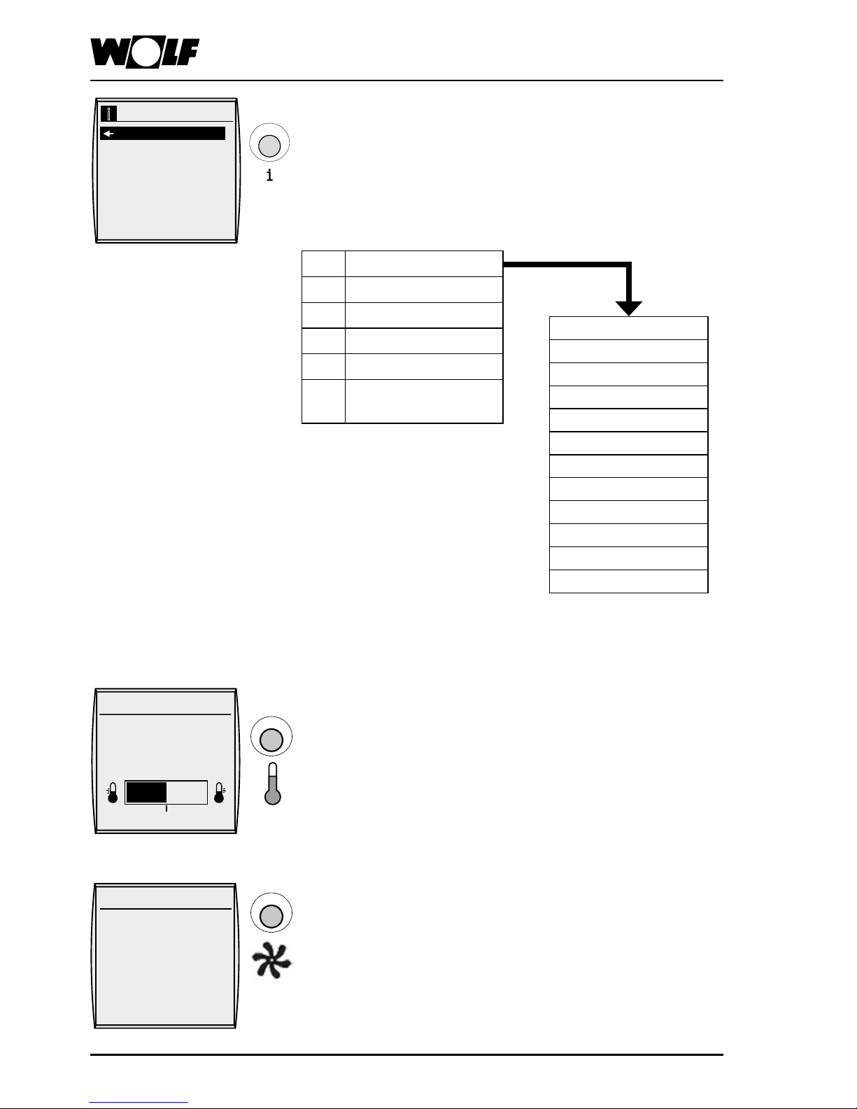
Info key
Please note: In the case of more than one zone (up to 7), rst
select the zone for which the values are to be scanned.
You can use the Info key to display current temperatures and system
values. Turning the r.h. rotary selector displays the following values.
Fire alarm
Fault zone
Frost protection room
External ON/OFF
Filter check
Standby
Summer ventilation
VA min limit heating
Night ventilation
Room temperature reached
Outside temperature shutdn
Control operation
Page 13
3063527_201308
13
Display explained
Room temperature, supply air temperature, extract air
temperature
The temperature shown on the display depends on the temperature
sensors connected. The sensor value displayed is as follows:
Only supply air sensor connected: display of supply air temperature
Only room sensor connected: display of room temperature
Supply air sensor + room sensor connected:
display of room temperature
Supply air sensor + extract air sensor connected:
display of extract air temperature
Time and outside temperature
The time and the outside temperature are displayed alternately
(subject to an outside temperature sensor being installed).
Day / date
Display of the currently set day and date.
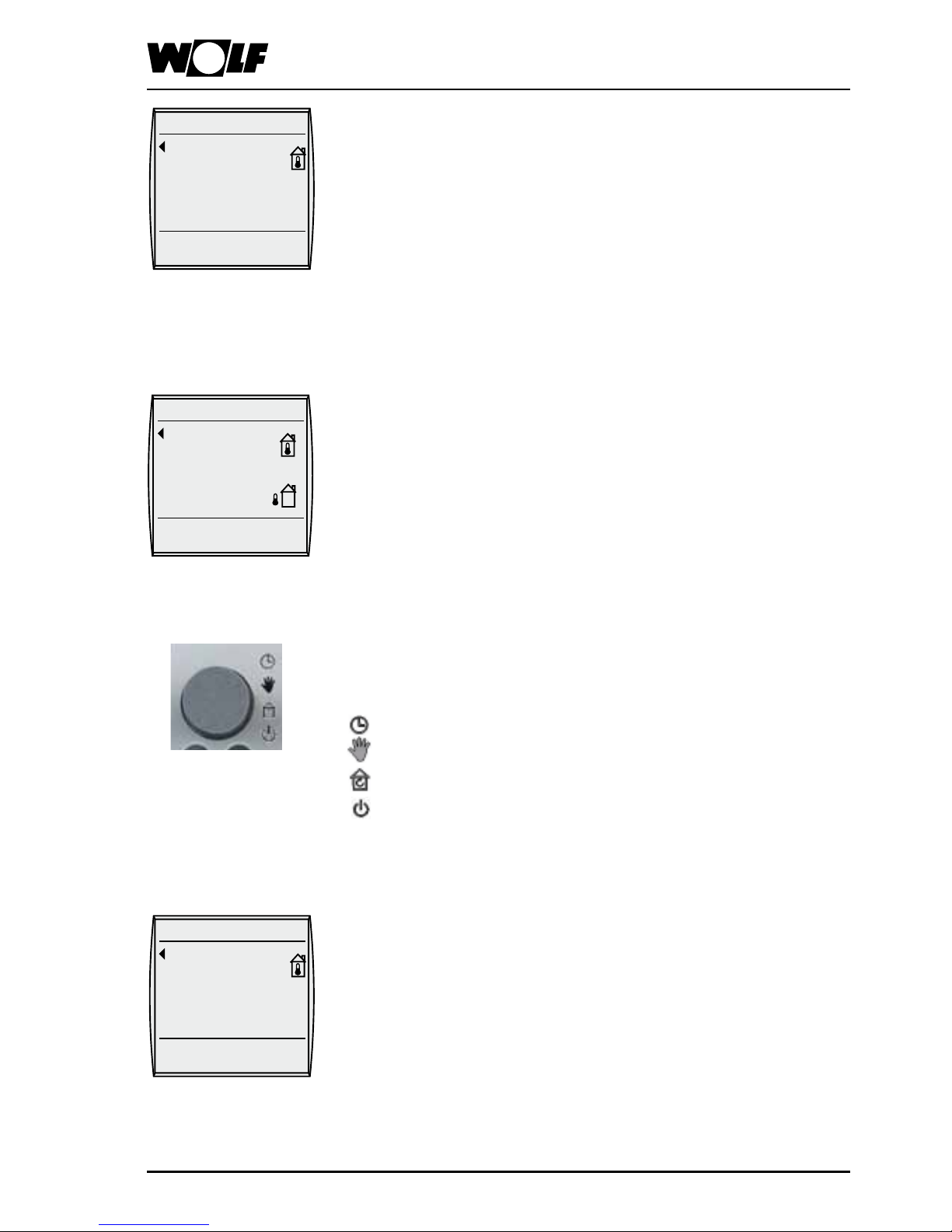
Status display
Symbols indicate the current operating state of your
ventilation system.
Clock = ventilation mode (heating) with time program
Manual = ventilation mode (heating) without time program
House = ventilation mode (summer mode)
with time program
Standby = system off or ventilation
(heating) ON/OFF via CO
2
sensor if
parameter LM163 set to ON
Indication of the current zone
If more than one zone is connected (up to 7)
you can select the zone you want by turning the r.h. rotary
selector.
20.0 °C
Friday
31/10/08
12 : 16
Zone 1
20.0 °C
Friday
31/10/08
10.0 °C
Zone 1
20.0 °C
Friday
31/10/08
12 : 16
Zone 1
Page 14
3063527_20130814
Control level 2 - Main menu
Back to the default display
Pressing the r.h. rotary selector calls up control level 2, where
you can select the menu levels shown in the overview by turning
the rotary selector clockwise. After selecting the parameter, you
enter the submenu by pressing the r.h. rotary selector again.
Pressing the Info key takes you back to the default display,
irrespective of which submenu is currently displayed.
The system also returns to the default display automatically when
no adjustment is made for more than one minute.
Overview
All available set and actual temperatures, the operating mode and
other system values can be displayed.
This is explained in the „Displays“ chapter.
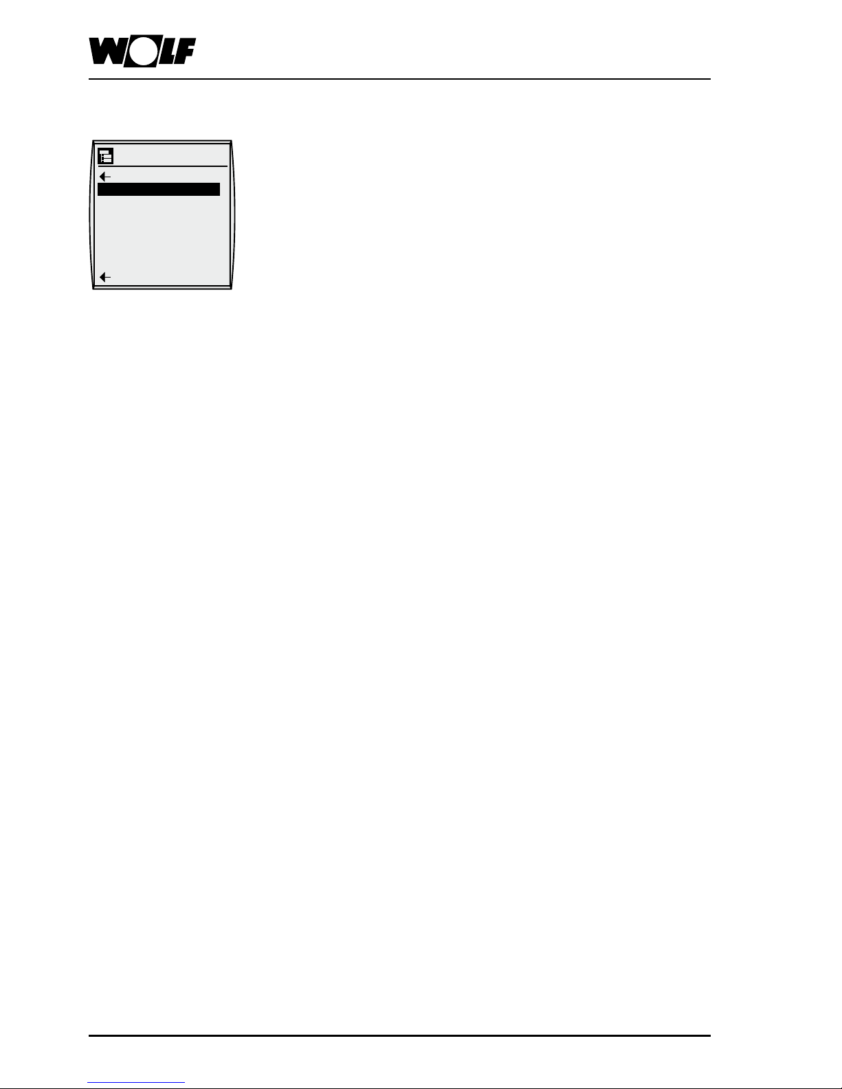
Displays
Acknowledging (resetting) faults that have occurred.
This is explained in the „Acknowledge faults.“ chapter.
Acknowledge faults
Setting of the most important parameters in the ventilation system
such as time, date, room temperature, night temperature, supply
air minimum limit for heating, backup temperature, night setback,
and night ventilation.
Setting options and explanations of the individual parameters are
given in the "Basic settings" chapter.
Basic settings
Modication of the time switch programs for heating operation.
Setting options and how to modify the individual time programs
are explained in the "Time programs" chapter.
Time programs
Setting the specialist's parameters for the ventilation system.
Setting options and explanations of the individual parameters are
given in the "Specialist" chapter.
Specialist
Five different holiday programs can be set. The holiday program
takes precedence over the normal switching time.
When the holiday program ends, the system returns to the previously
set time program automatically.
Holiday program
Main menu
Back
Fault ackn.
Basic settings
Time program
Holiday prog
Specialist
Back
Displays
Page 15
3063527_201308
15
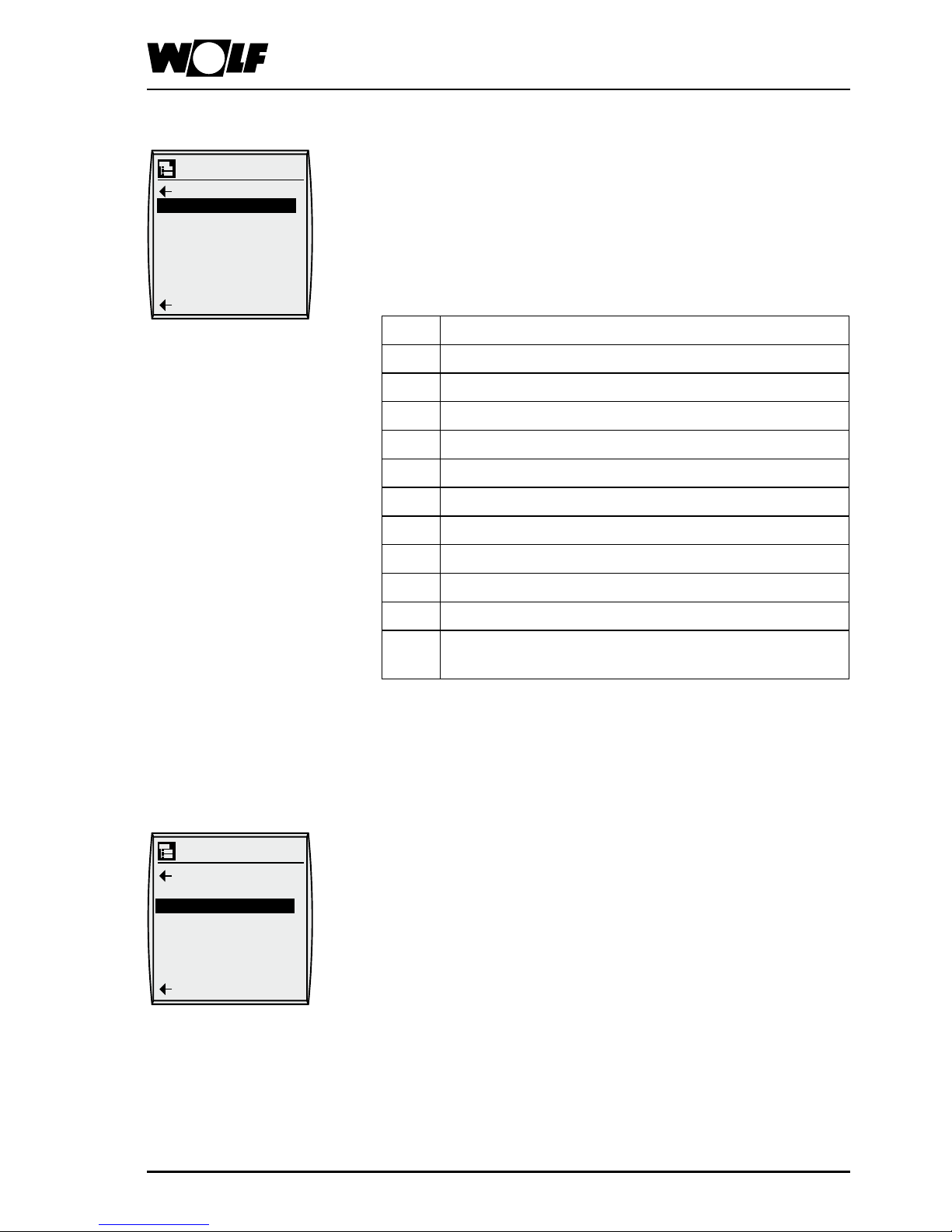
Displays Press the r.h. rotary selector to change to control level 2.
Turn the r.h. rotary selector clockwise to select the „Displays“
menu level and conrm the selection by pressing the r.h. rotary
selector again.
You can now display the following values in sequence by
turning the r.h. rotary selector.
Always select the zone rst in order to scan its values.
Control level 2 - Displays - Fault acknowledge
1 Operating mode
2 Current program
3 Extract air temperature
4 Set room heating
5 Outside temperature
6 Actual vent air temperature
7 Set vent air temperature
8 Motor speed
9 Heating mixer
10 Heat recovery
11 Conguration
12 Softwareversion LM x
Softwareversion LM y
Any sensors that are not connected are skipped, as only
available values can be displayed.
Acknowledge faults
Press the r.h. rotary selector to change to control level 2. Turn
the r.h. rotary selector clockwise to select the „Acknowledge
faults“ menu level and acknowledge faults by pressing the r.h.
rotary selector again.
After acknowledging faults, the display returns to the standard
mask immediately.
Main menu
Back
Fault ackn.
Basic settings
Time program
Holiday prog
Specialist
Back
Displays
Main menu
Back
Fault ackn.
Basic settings
Time program
Holiday prog
Specialist
Back
Displays
Page 16
3063527_20130816
Parameter Setting range Factory setting Individual
settings
Language German / English
French / Dutch
German
Date --.--.--
Time 0 to 24 h
Auto summertime AUTO / OFF AUTO
Key lock ON/OFF OFF
Z1 Zone 1 . . Z7 Zone 7
Day temperature 5 °C – 50 °C 20 °C
Economy temperature for
heating
5 °C – 30 °C 16 °C
Backup temperature for
heating
5 °C – 30 °C 12 °C
Speed adjustment 30 - 70 % 40 %
Setback program Econ. operation
Backup mode
Standby
Hols summer vent
Backup mode
VA min limit 5 °C – 30 °C 16 °C
Night ventilation enable ON/OFF ON
Parameter overview, default settings
(settings and functions on the following pages)
Control level 2 - Default settings
Main menu
Back
Fault ackn.
Basic settings
Time program
Holiday prog
Specialist
Back
Displays
Page 17

3063527_201308
17
Control level 2 - Default settings
Language
Press the r.h. rotary selector to change to control level 2.
Turn the r.h. rotary selector clockwise to select the "Default
settings" menu level and conrm the selection by pressing the
r.h. rotary selector again.
Select the Language parameter by turning the rotary selector
further clockwise, and conrm your selection by pressing the
selector again.
The language is changed by turning the r.h. rotary selector and
pressing to conrm.
You can cancel your input by pressing the „Speed adjustment
key “.
Factory setting: German
Options: German / English
French / Dutch
Basic settings
Back
Language
Date
Time
Autom. summert.
Key lock
Z1 Hall1
Press the r.h. rotary selector to change to control level 2.
Turn the r.h. rotary selector clockwise to select the "Default settings"
menu level and conrm the selection by pressing the r.h. rotary
selector again. Select the Date parameter by turning the rotary
selector further clockwise, and press selector to conrm.
Turn the r.h. rotary selector to change the date.
Enter the day, month and year one after the other, pressing the
r.h. rotary selector each time to conrm.
You can cancel your input by pressing the „Speed adjustment key“.
The date will be displayed automatically if a radio clock module is
connected. However, the date cannot then be changed.
Date
Basic settings
Back
Language
Date
Time
Autom. summert.
Key lock
Z1 Hall1
Press the r.h. rotary selector to change to control level 2. Turn the
r.h. rotary selector clockwise to select the "Default settings" menu
and conrm the selection by pressing the r.h. rotary selector again.
Select the Time parameter by turning the rotary selector further
clockwise, and press selector to conrm.
Then turn the r.h. rotary selector to change the time.
Enter the hours, minutes and seconds one after the other, pressing
the r.h. rotary selector each time to conrm.
You can cancel your input by pressing the „Speed adjustment key”.
You must set the time again if the control unit has been disconnected
from the power supply longer than 48 hours.
The time will be displayed automatically if a radio clock module is
connected. However, the time cannot then be changed.
Time
Basic settings
Back
Language
Date
Time
Autom. summert.
Key lock
Z1 Hall1
Page 18

3063527_20130818
Control level 2 - Default settings
Automatic summer time
Turn the r.h. rotary selector further clockwise to select the „Autom.
summert.“ parameter and conrm the selection by pressing the
r.h. rotary selector again.
„Automatic summertime“ is disabled by turning the r.h. rotary
selector and by pressing to conrm.
Factory setting: auto.
Options: auto / off
Key lock Press the r.h. rotary selector to change to control level 2. Turn
the r.h. rotary selector clockwise to select the "Default settings"
menu level and conrm the selection by pressing the r.h. rotary
selector again. Select the "Key lock" parameter by turning the
rotary selector further clockwise, and press selector to conrm.
The key lock is activated by turning the r.h. rotary selector and by
pressing to conrm.
You can cancel your input by pressing the „Speed adjustment key“ .
Note:
The key lock parameter is intended to prevent unintentional
adjustment of the ventilation system.
If the key lock parameter is set to "ON", the key lock will be activated
automatically one minute after the last adjustment.
No adjustments or scans can be implemented when the key lock
is enabled. If, nevertheless, a key or rotary selector is activated,
then the display shows KEY LOCK.
The key lock can be lifted for a single adjustment or to display
the set/actual values by holding down the r.h. rotary selector for
approx. three seconds.
To disable the key lock permanently, the "Key lock" parameter
must be set to "Off" again.
Function keys remain active
Speed adjust , fresh air proportion adjustment and temperature
correction).
Please note
Factory setting: off
Options: on / off
Basic settings
Back
Language
Date
Time
Autom. summert.
Key lock
Z1 Hall1
Basic settings
Back
Language
Date
Time
Autom. summert.
Key lock
Z1 Hall1
Page 19

3063527_201308
19
Control level 2 - Default settings
Select "Z1 Zone 1". If there is more than one zone in the
system, select the zone for which you want to change values
(max. 1-7) and conrm your selection by pressing the r.h. rotary
selector again. You can now modify the following values for
the selected zone one after the other by turning the r.h. rotary
selector.
Select and conrm Day temperature using the r.h. rotary
selector. Turn the r.h. rotary selector to set the required
temperature and then press to conrm.
Tagtemperatur
[Day temperature]
Factory setting: 20 °C
Range: 5 - 50 °C
Economy temperature
Heating
Select and conrm Economy temperature heating using the r.h.
rotary selector. Turn the r.h. rotary selector to set the required
economy temperature and press selector to conrm.
Factory setting: 16 °C
Range: 5 - 30 °C
Backup temperature
Heating
Select and conrm Backup temperature heating using the r.h.
rotary selector. Turn the r.h. rotary selector to set the required
backup temperature for heating and press selector to conrm
(see "Standard functions" - "Central heating backup mode").
Factory setting: 12 °C
Range: 5 - 30 °C
Basic settings
Back
Language
Date
Time
Autom. summert.
Key lock
Z1 Zone 1
Basic settings
Back
Day temperature
Econ temp htg
Backup temp htg
Speed adjust
Setback prog
Back
Basic settings
Back
Day temperature
Econ temp htg
Backup temp htg
Speed adjust
Setback prog
Back
Basic settings
Back
Day temperature
Econ temp htg
Backup temp htg
Speed adjust
Setback prog
Back
Z1 Zone 1
Page 20

3063527_20130820
Control level 2 - Default settings
Speed adjustment Select and conrm Speed adjustment using the r.h. rotary
selector. Turn the r.h. rotary selector to set the required speed
(30-70 %) and press selector to conrm.
Function:
The speed preselected here applies during day temperature,
backup mode, Summer ventilation and night ventilation and
cannot be reduced by the CO
2
sensor.
Factory setting: 40 %
Range: 30 - 70 %
Basic settings
Back
Day temperature
Econ temp htg
Backup temp htg
Speed adjust
Setback prog
Back
Setback
program
Select and conrm Setback prog. using the r.h. rotary selector.
Turn the r.h. rotary selector to set the required operating mode,
and press selector to conrm:
- Backup mode
- Economy operation (setback mode)
- Standby
- Summer ventilation
.
You can preselect the above operating modes when the time
program has switched off the system.
Backup mode function:
Backup mode can become active when the time program
switches the system off (this is the factory setting). If the
temperature in the room falls below the set backup temperature,
the fan, HR and reheater are activated until the backup
temperature is reached (+/- 1 K).
Backup mode = Economy mode: In the periods when the
system is not switched on by the time program, the fan is only
activated if the temperature falls below the backup temperature.
Factory setting: Backup mode
Range: Backup mode
Econ.operation
Standby
Summer ventil.
Basic settings
Back
Day temperature
Econ temp htg
Backup temp htg
Speed adjust
Setback prog
Back
Supply air minimum limit Select and conrm VA min limit using the r.h. rotary selector.
Turn the r.h. rotary selector to set the required supply air
minimum temperature and press selector to conrm.
Function:
The air blown into the room must be at or above this
temperature at all times. If the temperature falls below the set
value by the set hysteresis (2 K), HR and the reheater are
activated.
Please note:
The set temperature (for day, economy temperature) cannot be
set below the value of the minimum limit.
Factory setting: 16 K
Range: 5 - 30 K
Basic settings
Back
Econ temp htg
Backup temp htg
Speed adjust
Setback prog
VA min limit
Nght vent enable
Page 21

3063527_201308
21
Night ventilation enable
Select and conrm Night ventilation enable using the r.h. rotary
selector. Turn the r.h. rotary selector to set the required control
type (ON / OFF) and press selector to conrm.
Function:
This function is used in summer to supply the room with cool
outdoor air during periods when the system is not switched on by
the time program.
If the room temperature exceeds a certain value, the system is
switched on until the room temperature returns to the set value.
For a more detailed description, see "Additional functions".
This only works in backup mode
This function requires an outside temperature sensor and a
room sensor/extract air sensor.
Factory setting: off
Options: off / on
Control level 2 Default settings / time programs
Time program
Press the r.h. rotary selector to change to control level 2.
Turn the r.h. rotary selector clockwise to select the
"Time program" menu and conrm the selection by pressing
the r.h. rotary selector again.
Select the zone for which you want to program the switching times
and conrm by pressing.
Select the day for which you want to program the switching times
and conrm your selection by pressing the r.h. rotary selector again.
Turn the r.h. rotary selector to select the start time and press
selector to conrm.
Turn to set the required switching time and press selector to conrm.
Follow the same procedure for the end time.
You can then turn the r.h. rotary selector further to program switching
times 2-8 in the same way as described above.
When you have programmed all switching times for the selected
day, you can exit the menu with "Back".
Turn the r.h. rotary selector further to select „Copy day“ and conrm
the selection by pressing the selector again. You are automatically
taken to the copy area.
The source day of the week is displayed.
Turn the r.h. rotary selector to select the day you programmed
previously and press selector to conrm.
The target day of the week is displayed.
Select the day or block of days to which you want to copy the
switching times and press selector to conrm.
Copy selection: Mo, Tu, We, Th, Fr, Sa, Su
Mo - Th
Mo - Fr
Sa - Su
Basic settings
Back
Econ temp htg
Backup temp htg
Speed adjust
Setback prog
VA min limit
Nght vent enable
Time program
Zonenübersicht
Back
Z1 Zone 1
Z2 Zone 2
Time program
Zone 1
Thursday
Friday
Saturday
Sunday
Copy day
Zone 1
Monday
Start time 07 : 00
End time 14 : 00
Start time 07 : 00
End time 14 : 00
Start time 07 : 00
End time 14 : 00
Back
Back
Back
Page 22

3063527_20130822
Control level 2 - Time programs
If no switching time is entered, that means the system is shut down.
Each day of the week begins at 0:00 h and ends at 23:59 h.
Time program for zone 1 - factory setting
Zone 1
Time
program
1
Time
program
2
Time
program
3
Time
program
4
Time
program
5
Time
program
6
Time
program
7
Time
program
8
Monday
On 07:00
Off 14:00
Tuesday
On 07:00
Off 14:00
Wednesday
On 07:00
Off 14:00
Thursday
On 07:00
Off 14:00
Friday
On 07:00
Off 14:00
Saturday
On --:--
Off --:--
Sunday
On --:--
Off --:--
Page 23

3063527_201308
23
Press the r.h. rotary selector to change to control level 2.
Turn the r.h. rotary selector clockwise to select the „Holiday program“
[Holiday program] menu and conrm the selection by pressing the
r.h. rotary selector again.
Select the zone for which you want to program the holiday times
and conrm by pressing the selector.
Select the holiday program (from 1 to 5) for which you want to
program the holiday times and conrm your selection by pressing
the r.h. rotary selector again.
Turn the r.h. rotary selector to select the date for holiday start and
press selector to conrm.
Turn to set the required date and press selector to conrm.
Follow the same procedure to set the time.
Then set the date and time for holiday end.
Next, under Prog. selection, select "Standby" and
conrm by pressing the selector.
You can select from the following:
- Standby (factory setting)
- Backup mode
- Econ.operation
- Hols day mode
- Summer ventil.
Follow the same procedure for holiday programs 2 to 5.
Holiday prog
Control level 2 - Holiday prog
Holiday prog
Zone overview
Back
Z1 Zone 1
Z2 Zone 2
Back
Holiday prog Zone
1
Back
Holiday prog 1
Holiday prog 2
Holiday prog 3
Holiday prog 4
Holiday prog 5
Back
Holiday prog
Zone 1
Back
Holiday start
Date 01/01/09
Time 00:00
Holiday start
Date 01/01/09
Time 00:00
Prog. selection
Standby
Back
Page 24

3063527_20130824
Control level 2 - Specialist
You can use the BML programming module to set the parameters
of the ventilation units.
Setting options and explanations of the individual parameters are
given in chapter
Control level 3 - Specialist - System parameters.
After selecting the zone and conrming the selection, the data is
retrieved from the ventilation appliance control unit and displayed
approx. 5 seconds later.
If the parameter is present in the ventilation appliance control
unit, the
value currently set for it will be shown in the display and can be
modied.
Press the r.h. rotary selector to change to control level 2. Turn the
r.h. rotary selector clockwise to select the "Specialist" menu level
and conrm the selection by pressing the r.h. rotary selector again.
Turn the r.h. rotary selector to enter the digit 1 and conrm it.
Repeat this three times (to enter password 1111).
After entering this code, you will be in specialist level 3.
Password requirement
If modules are removed from the system or existing systems are
extended or modied with modules, a re-conguration must be
carried out.
The re-conguration process is completed when „New congurat“
is selected and conrmed.
If a temperature sensor is removed from the system or one is
retrotted after commissioning, sensor detection must be carried
out.
The sensor detection process is completed when „Sensor check“
is selected and conrmed.
New congurat /
Sensor check
Zone designat Any text can be entered as the Zone designat for the zone, e.g.
Restaurant.
With the r.h. rotary selector, select the required zone (from
zones 1 to 7) in the "Specialist" menu level (after entering the
code) and press selector to conrm.
Select the Zone designat parameter and press selector to
conrm.
Use the r.h. rotary selector to enter your selection (letters,
numbers, symbols, etc.).
Conrm the selected character with the r.h. rotary selector.
You can then enter the next character.
You can enter up to 16 characters.
=
User password
authorisation
required.
Cancel
Specialist
System
Z1 Zone 1
Z2 Zone 2
Back
Back
Back
System
New congurat
Sensor check
Back
=
Zone 1
Cancel
Zone designat
Restaurant
Page 25

3063527_201308
25
Control level 3 - Specialist - System parameters
Ventilation unit
parameters
The settings can be modied for LM001 to LM204.
See "Specialist parameter list - Overview"
Specialist
Zone designat
LM001 K20
LM015 25 %
LM016 70 %
LM017 10 K
LM018 93
LM023 ON
Back
Relay test
Relay test can be used to activate the outputs for particular
modules.
With the r.h. rotary selector, select the required zone (from
zones 1 to 7) in the "Specialist" menu level (after entering the
code) and press selector to conrm.
Select the "Relay test" parameter and press selector to conrm.
Use the r.h. rotary selector to make your selection (see below)
and press selector to conrm (for relay assignment, see
terminal assignments).
- Rel o.air open
- Rel o.air cl.
- Inverter relay
- Analogue Y1
- Analogue Y2
- Analogue Y3
- Analogue T1
This function can be used to activate the individual outputs
in sequence. When you exit the menu, relay test is disabled
automatically and the system returns to the previously selected
operating mode.
Specialist
LM203 1000
Relay test
Off
Zone designat
Back
Zone reset You can use Zone reset to reset all the parameters saved on a
module to their factory settings.
With the r.h. rotary selector, select the required zone (from
zones 1 to 7) in the "Specialist" menu level (after entering the
code) and press selector to conrm.
Select the Zone reset parameter and press selector to conrm.
The following values are reset to their factory settings:
- Zone parameters
- Time program
- Default settings
- Holiday prog
Specialist
LM203 1000
Relay test
Off
Zone reset
Back
Page 26

3063527_20130826
Specialist parameter list - Overview
Parameter Setting
range
Factory
setting
Individual
settings
LM001 Conguration
-
K20
LM013 Hysteresis OFF 0-3 K 1 K
LM015 Minimum fan speed 5 % - 60 % 30 %
LM016 Maximum fan speed 25 % - 100 % 70 %
LM017 P component for speed control 1 - 20 10
LM018 Ratio of extract air to supply air
fan speed
50 - 150 93
LM020 Weather-compensated
winter/summer changeover
ON/OFF OFF
LM021 Differential for heating 1 K – 20 K 1 K
LM023 Room frost protection ON/OFF ON
LM024 Room frost protection
temperature
0 °C – 30 °C 5 °C
LM060 Fan speed for Economy
operation, speed control preselection for backup mode, night
ventilation, summer mode, room
frost protection
40 % - 100 % 70 %
LM080 P component for heating circuit
mixer
5 - 20 12
LM081 Integral action time for heating
circuit mixer
0 - 25 min 2 min
Control level 3 - Specialist - System parameters
Setting parameters With the r.h. rotary selector, select the required zone (from
zone 1 to 7) in the "Specialist" menu level (after entering a
password) and press selector to conrm.
Select the ventilation unit parameter (LM...) you want to
modify, conrm by pressing the selector and then modify
it by turning the r.h. rotary selector. Once you have set the
ventilation unit parameter (LM...) you wanted to modify, press
the r.h. rotary selector again to conrm the setting.
Specialist
Zone designat
LM001 K20
LM015 25 %
LM016 70 %
LM017 10 K
LM018 93
LM023 ON
Back
Page 27

3063527_201308
27
LM100 Cascade effect 0 - 20 2
LM101 Integral action time for cascade 0 - 25 min 2 min
LM102 Supply air maximum limit 20 - 60 °C 50 °C
LM103 Control type Supply air control,
cascade control
Supply air
control
LM114 Damper lead time 0 - 150 s 120 s
LM130 Night ventilation limit 10 - 30 °C 22 °C
LM131 Night ventilation start condition
differential TR > TA
2 K - 20 K 5 K
LM132 Night ventilation, minimum
outside temperature
5 - 20 °C 12 °C
LM150 P component for HR 5 - 20 12
LM151 Integral action time for HR 0 - 25 min 2 min
LM160 Air quality control OFF/ON ON
LM161 Air quality, start 0 - 10 V 4 V
LM162 Air quality, maximum 0 - 10 V 8 V
LM163 System OFF/ON via air quality OFF/ON OFF
LM180 Alarm function, re dampers (OFF) System
Off
(ON) Message
only
System OFF
LM190 Delay for
air ow fault
5 - 600 s 60 s
LM200 Active lter monitor ON/OFF OFF
LM201 Filter check interval 1 -10 weeks 1 week
LM202 Service message
via hours run
ON/OFF OFF
LM203 Fan hours run 100 - 8000 1000
LM204 Filter check ON/OFF OFF
Parameter Setting
range
Factory
setting
Individual
settings
Control level 3 - Specialist - System parameters
Page 28

3063527_20130828
Parameters / Function description
Parameter description The specialist parameters listed in the table in the last section
are described in detail below.
The column on the left shows the designation of each
parameter and its number.
Not all parameters listed in the table will be present in every
system conguration.
Hysteresis OFF
LM013
Factory setting: 1 K
Range: 0 - 3 K
The heating control by temperature stops if the currently
actual room temperature or extract air temperature exceeds
the set temperature by the Hysteresis OFF value.
Minimum fan speed
LM015
Factory setting: 30 %
Range: 5 - 60 %
Min. speed "n-min" (minimum output voltage)
Setting (if required) of a minimum output voltage, i.e. a base
speed (minimum air change) for the connected fans which
must be maintained during temperature control and CO2
control.
Never set below 30 %!
Maximum fan speed
LM016
Factory setting: 70 %
Range: 25 - 100 %
Max. speed "n-max" (maximum output voltage)
Setting (if required) of a maximum output voltage, i.e. a speed
limit (to prevent excessive air noise) for the connected fans
which must not be exceeded during temperature control and
CO
2
control.
P component
for speed control
LM017
Factory setting: 10
Range: 1 - 20
The P component for speed control determines how sharply
the output signal of the Analogue output is modied in
proportion to a control deviation. (0-100 %)
If the P component is set low, the control unit responds more
quickly.
If the P component is set high, the control unit responds more
slowly.
Ratio of extract air/
supply air fan speed
LM018
Factory setting: 93
Range: 50 - 150
In order to run air handling systems so that positive or
negative pressure is created in the room, the speeds of the
supply air and extract air fans must be set differently.
Setting LM018 at 100 → parallel operation
LM018 at > 100 → negative pressure
LM018 at < 100 → positive pressure
Weather-compensated
summer shutdown
LM020
Factory setting: OFF
Range: ON/OFF
By enabling this parameter, the system can be switched on
and off according to the outside temperature.
The system must be connected to an outside temperature
sensor for this function to be available (see "Additional
functions"). In the control panel, disconnect the internal wires
across terminals X2 21/22 and connect the external outside
temperature sensor.
Enable this parameter only if you are replacing an
internal temperature sensor with an outside temperature
sensor one.
Page 29

3063527_201308
29
Differential for heating
LM021
Factory setting: 1
Range: 1 - 10 K
This parameter denes the outside temperature, relative to
the set room temperature, at which the ventilation unit stops.
Example:
Set room temperature 20 °C, parameter LM021 set to 5.
If the outside temperature is > 25 °C the ventilation unit
will be switched off. At 1 kelvin below that, the unit will be
enabled again.
Room frost protection
LM023
Factory setting: ON
Range: ON/OFF
Activating this parameter allows the system to be switched
on when the room temperature falls below the room frost
protection limit.
Room frost protection
temperature
LM024
Factory setting: 5
Range: 0 - 30 °C
If the room temperature falls below the set value, the reheater
and the fan are activated. Once the temperature rises 2 K
above the set temperature, the system stops again.
The fan speed can be preselected manually.
Fan speed for
Econ.operation
LM060
Factory setting: 70 %
Range: 40 - 100 %
When Economy operation is active, the fan is operated at the
speed preselected here. The set speed applies to backup
mode, night ventilation, summer mode and peak ventilation.
P component for
heating circuit mixer
LM080
Factory setting: 12
Range: 5 - 20
The P component for the heating circuit mixer (HR)
determines how sharply the output signal of the heating
circuit mixer is modied in proportion to a control deviation.
If the P component is set low, the control unit responds more
quickly.
If the P component is set high, the control unit responds more
slowly.
Integral action time for
heating circuit mixer
LM081
Factory setting: 2 min.
Range: 0 - 25 min.
The integral action time for the heating circuit mixer (HR)
determines how great the time effect is on the output signal of
the heating circuit mixer due to a control deviation.
If the integral action time is set low (high time effect), short
correction times result. However, so do greater uctuations
around the set value. If the integral action time is set high,
longer correction times result. This also means lesser
uctuations around the set value.
Cascade effect
LM100
Factory setting: 2
Range: 0 - 20
The cascade effect determines how sharply the set
temperature for supply air is modied in proportion to a
control deviation in the room temperature.
If the P component is set low (low gain), longer correction
times result, whilst uctuations around the set value will be
minor. If the P component is set high, shorter correction times
result. However, so do greater uctuations around the set
value.
Parameters / Function description
Page 30

3063527_20130830
Integral action time for
cascade
LM101
Factory setting: 2 min.
Range: 0 - 25 min.
The cascade integral action time determines how great the
time effect is on the set temperature for supply air due to a
control deviation in the room temperature.
If the integral action time is set low (high time effect), shorter
correction times result. However, this also means greater
uctuations around the set value. If the integral action time
is set high, longer correction times result. This also means
lesser uctuations around the set value.
Supply air maximum limit
LM102
Factory setting: 50 °C
Range: 20 - 60 °C
The supply air maximum limit determines the maximum
temperature at which supply air can be blown into the room.
If the differential in temperature between the set temperature
and the actual temperature is high, control based on room
temperature could lead to very warm air being conveyed into
the room. This high supply air temperature would cause the
air quality in the room to worsen. To prevent that, the supply
air temperature is limited to a maximum value in the case of
heating.
Temperature - control
type
LM103
Factory setting:
Supply air temperature control
This parameter sets the type of temperature control.
- Auto
- Supply air temperature control
- Extract air:supply air cascade
For a detailed description of the control functions, see BML.
Damper lead time
LM114
Factory setting: 0 s
Range: 0 - 150 s
To prevent whistling noises occurring on the dampers when
the fan is switched on, the outside air dampers are opened
rst, with the fans being switched on after this time (60 s) has
elapsed.
Night ventilation limit
LM130
Factory setting: 22 °C
Range: 10 - 30 °C
If night ventilation is activated (DEFAULT SETTING), this
parameter is used to determine the room temperature or
extract air temperature at which night ventilation starts or
stops (±1 K).
Night ventilation starts if the room or extract air temperature is
higher than the set value ± 1 K.
Night ventilation stops if the room or extract air temperature is
lower than the set value.
Night ventilation
start condition
LM131
Factory setting: 5 K
Range: 2 - 20 K
If night ventilation is activated (DEFAULT SETTING), this
parameter sets the outside temperature, relative to room
temperature, at which night ventilation starts.
Night ventilation starts when the outside temperature is lower
than the room temperature minus the "Night ventilation start
condition" parameter.
Parameters / Function description
Page 31

3063527_201308
31
Night ventilation,
minimum outside
temperature
LM132
Factory setting: 12 °C
Range: 5 - 20 °C
The "Night ventilation minimum outside temperature"
parameter sets the minimum outside temperature below
which night ventilation is disabled.
P component for HR
LM150
Factory setting: 12
Range: 5 - 20
The P component for HR determines how sharply the output
signal of the HR damper is modied in proportion to a control
deviation.
If the P component is set low, the control unit responds more
quickly.
If the P component is set high, the control unit responds more
slowly.
Integral action time for
HR
LM151
Factory setting: 2 min
Range: 0 - 25 min
The integral action time for HR determines how great the
time effect is on the output signal of the HR damper due to a
control deviation.
If the integral action time is set low (high time effect), shorter
correction times result. However, this also means greater
uctuations around the set value. If the integral action time
is set high, longer correction times result This also means
lesser uctuations around the set value.
Air quality control / CO2
LM160
Factory setting: ON
Options: OFF - ON
If the system is equipped with an air quality sensor / CO2
sensor, this parameter must be set to ON in order to make
this function available.
Air quality / CO2
start
LM161
Factory setting: 4 V
Range: 0 - 10 V
If air quality control is enabled, this parameter denes the
default value from which the speed is increased.
Air quality / CO2
maximum
LM162
Factory setting: 8 V
Range: 0 - 10 V
If air quality control is enabled, this parameter denes the
default value at which the maximum speed is reached.
Observe compliance with the limits set by parameters LM015,
LM016.
Parameters / Function description
Page 32

3063527_20130832
System OFF/ON
via air quality / CO
2
LM163
Factory setting: OFF
Options: OFF - ON
If you want the system to be switched on an off according to
the air quality (CO2 content), this parameter must be set to
ON.
In order to use this function, the operating mode selector
must be set to standby or setback mode with standby must
be preselected.
This function is only possible in the standby mode.
The CO2 sensor should be located inside the room.
Alarm function,
re dampers
LM180
Factory setting: OFF
Options: ON/OFF
There are different possible responses when a re alarm
damper responds.
Setting OFF: The fans are switched off and all outputs are set
to 0. A fault message is displayed on the BML programming
module.
Setting ON: The system continues running in control mode;
only a fault message is displayed on the BML programming
module.
Delay for
air ow monitor
LM190
Factory setting: 60 s
Range: 5 - 600 s
If the differential pressure cell for air ow monitoring
responds, the system stops after the delay time set here
(fans off, all outputs set to 0).
A fault message appears on the BML programming module.
Active lter monitor
LM200
Factory setting: OFF
Options: ON/OFF
If there is a lter monitor (differential pressure cell) installed in
the ventilation unit, this parameter must be set to ON. If set to
OFF, lters will not be monitored.
Filter check interval
LM201
Factory setting: 1 week
Range:1 -10 weeks
Subject to setting, the process is as follows:
After the motor starts, lters are checked after the test interval
has elapsed. Fan runs at 100 % speed, and after a delay of 60 s
a fault message is issued on the BML programming module if
lters are dirty. The system resumes its control mode and the
fan speed is reset again. If the system continues running day
and night, a lter check will be carried out after the test interval
has elapsed plus 24 hours.
Filter service message
LM202
Factory setting: OFF
Options: ON/OFF
If there is no active lter monitoring input, this parameter can
be used to enable the lters to be reported as dirty according
to the number of hours that the fans have been running.
Fan hours run
LM203
Factory setting: 1000 h
Range: 100 - 8000 h
Here you can set the number of hours of fan operation after
which the lters should be reported as dirty.
Filter check
LM204
Factory setting: OFF
Options: ON/OFF
If set to "ON" a lter check can be carried out immediately
(checking of cable/differential pressure cell), otherwise test
procedure as described under LM201
Please note: Parameter LM200 must be set to "ON" to be
able to activate a lter check.
Parameters / Function description
Page 33

3063527_201308
33
Master reset / Standard functions
Master reset
Take the programming module (BML) in the ventilation unit out
of its wall mounting base and clip it back in again while holding
down the r.h. selector.
Hold the selector down until Parameter reset appears on the
display.
The following values are reset to their factory settings:
- Zone designat
- Language
- Key lock
- Auto summertime
- System parameters
Please note
Also carry out a master reset if an eBUS error occurs when the
system is rst switched on.
Standard functions The standard functions of the controller are described below.
Motor protection The motor winding temperature is monitored with the aid of
thermistors set into the motor windings or PTC thermistor
pellets.
If the winding temperature rises above the dened value, the
motor and all outputs are switched off. A fault message is
displayed on the programming module. The motor will only
restart once the fault is removed (motor cooled down) and the
fault message is reset.
The fault is reset by acknowledging the fault on the BML
programming module.
Relevant parameters: none
Room frost protection
(room sensor)
The room frost protection function prevents the room from
cooling down too much, thereby preventing damage to the
building that might otherwise result
(moisture damage, mould growth, etc.).
Relevant parameters:
Room frost protection on (LM023),
Room frost protection temperature (LM024)
Pre-requisites:
Room sensor / extract air sensor
If the room temperature falls below the set value, HR,
the reheater and the fan are activated and the outside air
dampers are opened. Once the temperature rises 1 K above
the set temperature, the system stops again.
This works in all operating modes
Page 34

3063527_20130834
Standard functions
Backup mode, heating If backup mode is enabled, and the current room temperature
falls below the backup temperature (DEFAULT SETTING),
the fan is run at the preselected speed and HR and the
reheater are activated. Once the current room temperature
rises 1 K above the backup temperature, everything stops
again.
Relevant parameters:
Program selector, time program, in OFF mode, backup
temperature, night mode
Supply air minimum limit
for heating
If the supply air temperature (temperature of air blown in)
falls below the set minimum limit value, the heating mixer is
activated (100 %) (HR and reheater coil).
The heating modules are not switched off again until the
temperature has risen above the set value.
In addition, if the supply air temperature falls below the
minimum limit, the current fan speed is set to the minimum
speed (parameter LM 015) after 900 s have elapsed. If the
supply air minimum limit then ceases to be active, the fan
speed is returned to its nominal speed.
If the supply air minimum limit is still active after 5 minutes
despite the speed reduction, a fault message is issued (and
the system shuts down).
This will be reset automatically once 5 hours have elapsed or
when the fault is acknowledged on the BML.
Filter contamination
fault trigger
Parameters LM202 and LM203 can be used to activate a lter
fault by means of the number of hours of fan operation.
Active lter monitor A differential pressure cell can be used to trigger a fault
message when the lter is dirty; see parameter LM200.
Fan run-on time To prevent re-heating by the electric heater coil, the fan stops
only after a run-on time of 45 seconds after system shutdown.
External ON/OFF An on-site contact can be used to switch the system on and
off within the time program.
Contact closed:
System runs according to the time program
Contact open:
System switched off by time program
If the system is always going to be operated via the external
switch, the time program must be enabled 24 hours a day
The additional functions of the controller are described below.
Additional functions
Page 35

3063527_201308
35
Additional functions
Room/supply air
cascade control
With room/supply air cascade control, the set supply air
temperature is corrected according to the control deviation of the
room temperature.
Relevant parameters:
Cascade effect LM100, integral action time for cascade LM101,
supply air minimum limit (default setting), supply air minimum limit
LM102
Pre-requisites:
Room sensor (extract air sensor) and supply air sensor
The set supply air temperature is dependent on the load
conditions in the room. The actuating variable from the room
temperature control is transferred as set value to the supply air
temperature control. This results in the set supply air temperature
being varied according to the deviation in room temperature.
Night ventilation In summer, night ventilation pre-cools the room for the
following day with cool outdoor air.
Relevant parameters:
Night ventilation limit LM130; start condition Tr > Ta LM131;
permissible outside temperature LM132
Pre-requisites:
- Room sensor (extract air sensor) and outside temperature
sensor are installed
- Time program set to "OFF"
- Outside temperature > minimum outside temperature
(LM132)
- Outside temperature < room temperature + delta (LM131)
- Room temperature > set room temperature (LM130)
- Works only when backup mode is selected
- Enabled from 1 March to 31 October
- Enabled from 20:00 to 07:00 h
Effects:
- Fans are switched on
- Speed according to parameter LM060
- HR heater coil is switched off
- Outside air dampers are opened
- Set temperatures for switching night ventilation on and off
are dened by parameter LM130.
When night ventilation is activated, sensor values are
checked for the rst 7 minutes.
(Fan speed according to parameter LM 060; checking
outdoor air, extract air/room air temperatures.)
If the conditions dened by parameters LM 130 - LM 132 are
met, night ventilation continues. If the conditions are not met,
night ventilation stops again.
If, during the time in which night ventilation is enabled, a
shutdown occurs (temperature below threshold in parameter
LM 130), another sensor check is activated after 125 minutes
and runs for 7 minutes.
In order to use night ventilation efciently, the outside
temperature sensor in the appliance should be disabled and
shifted outside.
Page 36

3063527_20130836
Additional functions
Preheater coil for HR
Ice guard,
Filter drying
When the outside temperature is below 0 °C, the preheater
coil is activated.
Once the temperature rises to the set temperature +
hysteresis, the preheater coil is switched off again.
Condensate overow When a condensate pump is connected, the amount of
condensate is monitored. If the limit is exceeded, the
ventilation unit stops and a fault message is issued on the
BML (active only with cooling congurations).
Summer shutdown With parameters LM020 / LM021, ventilation can be
switched off automatically in the event of very high outside
temperatures to prevent the interior getting too hot.
When summer shutdown is activated, the outside
temperature sensor in the appliance must be disabled and an
external outside temperature sensor used.
Heat recovery In many industrial plants, waste heat from cooling circuits/
lighting is available. Heat recovery allows the utilisation of
this free heat source for heating purposes. With a crossow
heat exchanger, energy costs can be drastically reduced in
this way.
Heat recovery is actuated by an Analogue control signal
(0-10 V). Heat recovery is applied for heating and cooling
purposes by capturing and comparing the room (extract air)
temperature, the outside temperature and the supply air
temperature.
HR actuation takes priority over the actuating signal for
heating. The reheater coil is not activated unless and until
the HR control signal is at 10 V and the set temperature has
still not been reached.
Relevant parameters:
P band for HR LM150, integral action time for HR LM151
The parameters are switched to active only in accordance
with the conguration
Function is only supported in conjunction with an outside
temperature sensor/room sensor or extract air sensor.
HR ice guard To prevent frost forming on the extract air side of the HR
system, the extract air temperature is captured by an ice
guard sensor and if the temperature falls below +6 °C, the HR
system is steadily closed. At 1 °C the HR system is closed
completely. The heating valve continues to be controlled
towards its set value independently. If the temperature stays
below the icing-up temperature for more than 2 minutes, a
fault message is issued. The fault message automatically
extinguishes when the temperature rises above the limit
temperature. Ice guard function does not become active until
the fan has been running for at least 5 minutes.
Page 37

3063527_201308
37
Peak ventilation:
CO2 sensor diagram
NTC
sensor resistances
Outside temperature sensor, room sensor, supply air sensor,
extract air sensor
Sensor resistances
Temp. °C Resist. Ω Temp. °C Resist. Ω Temp. °C Resist. Ω Temp. °C Resist. Ω
-21 51393 14 8233 49 1870 84 552
-20 48487 15 7857 50 1800 85 535
-19 45762 16 7501 51 1733 86 519
-18 43207 17 7162 52 1669 87 503
-17 40810 18 6841 53 1608 88 487
-16 38560 19 6536 54 1549 89 472
-15 36447 20 6247 55 1493 90 458
-14 34463 21 5972 56 1438 91 444
-13 32599 22 5710 57 1387 92 431
-12 30846 23 5461 58 1337 93 418
-11 29198 24 5225 59 1289 94 406
-10 27648 25 5000 60 1244 95 393
-9 26189 26 4786 61 1200 96 382
-8 24816 27 4582 62 1158 97 371
-7 23523 28 4388 63 1117 98 360
-6 22305 29 4204 64 1078 99 349
-5 21157 30 4028 65 1041 100 339
-4 20075 31 3860 66 1005 101 330
-3 19054 32 3701 67 971 102 320
-2 18091 33 3549 68 938 103 311
-1 17183 34 3403 69 906 104 302
0 16325 35 3265 70 876 105 294
1 15515 36 3133 71 846 106 285
2 14750 37 3007 72 818 107 277
3 14027 38 2887 73 791 108 270
4 13344 39 2772 74 765 109 262
5 12697 40 2662 75 740 110 255
6 12086 41 2558 76 716 111 248
7 11508 42 2458 77 693 11 2 241
8 10961 43 2362 78 670 113 235
9 10442 44 2271 79 670 114 228
10 9952 45 2183 80 628 115 222
11 9487 46 2100 81 608 11 6 216
12 9046 47 2020 82 589 117 211
13 8629 48 1944 83 570 118 205
Connect external oating contact to input B5. The speed
is ramped up as set in parameter LM060. The speed is not
ramped down again (control operation) until the contact
switches off. This works in all operating modes (On/Off switch
function).
CO
2
control An external contact can be used to switch the system off or
simply issue a fault; see parameter LM180.
The fan speed is adjusted according to the CO
2
content of the
room air.
Relevant parameters: LM015, LM016, LM160, LM161, LM162
This function is only supported in conjunction with a CO2
sensor.
Page 38

3063527_20130838
Specication
Specication,
CGL control unit
Supply voltage: 230 V
Power consumption: max. 3 W
IP rating: IP54 control panel
Ambient temp.: 0....50 °C
Storage temperature: -20....+60 °C
Data memory: EEPROM (non-volatile)
Relay contact breaking
capacity (servomotor): 230 V/1 A/0.5 A
Max. power consumption, 10 VA
Actuators X1 - X3 (Y1 - Y3)
Specication, BML
Supply voltage: eBUS 15-24 V
Power consumption: max. 3 W
IP rating: IP30 wall mounting base
Battery backup: > 48 h
Ambient temp.: 0....50 °C
Storage temperature: -20....+60 °C
Data memory: EEPROM (non-volatile)
Dimensions: H/W/D 100 x 145 x 45 mm
Page 39

3063527_201308
39
System conguration
This conguration is used for the ventilation of buildings. The
room/extract air temperature is captured by a sensor, with HR
and the reheater coil being switched on and off according to
demand.
The fan speed is adjusted via a CO2 sensor (accessory).
Description:
System layout:
LM001 conguration K20 Ventilation unit with room or extract air temperature
control, variable fan motor control via 0-10 V signal
(EC motors). Plus installed heat recovery systems
CO
2
-dependent speed adjustment
Condensate
pump (accessory)
F5 compact lter,
extract air
Condensate pan
Countercurrent
plate heat exchanger
Bypass damper with
servomotor
Adjustable feet
Temperature sensor,
extract air
Control panel
Repair switch
Power cable
Programming unit
of BML control unit
F7 compact lter,
supply air
Temperature sensor,
outdoor air
Filter pre-drying
(accessory)
SUP
EHA
ODA
Temperature sensor,
supply air
Silencer,
exhaust air
Silencer,
supply air
EC fan,
extract air
EC fan,
supply air
Reheater
(accessory)
Intake grille
CO
2
sensor
(accessory)
ETA
Differential pressure cell
Electrical connection
for EHA and ODA
dampers
Ice sensor
Differential pressure cell
Page 40

3063527_20130840
Terminal assignments
Terminal assignments: Module address 1
Standard functions:
Motor protection
Room frost protection
Central heating backup mode
External ON/OFF
Filter monitor
Fire alarm
Operating message
Central fault message
Additional functions: Night ventilation
Supply air control or
extract/supply air cascade
HR control
CO
2
control
Mains
230 V AC
Switching lter
pre-drying
Room
sensor/
extract air
sensor
Servomotor,
EHA and ODA
dampers
230 V/0.5 A
Open-Close
BML
as RC
Fault input
- motors
External
contact
(switch)
for peak
ventilation
Control signal,
reheater
0-10 V DC
Servomotor,
bypass damper
24 V / 0-10 V DC
CO
2
sensor
Supply air
sensor
Control signal,
0-10 V
Supply air motor
Control signal,
0-10 V
Extract air motor
Central
fault message
24 V DC
▲
▼
▲
▼
▲ ▲
▲
▲
▼
▼
▼ ▼
▼
▼
24 V DC operating
message
▼
▲ ▲ ▲ ▲
External
On/Off
Condensate
Fire 1 Filters
Ice sensor
▲
Page 41

3063527_201308
41
Fault messages are issued to the programming unit with plain
text, info no. and a symbol
The display shows:
(e.g. "Fault zone, 207 - motor protection")
Troubleshooting:
1. Check whether the motor protection on the supply/extract
air fan has responded. Do so by measuring across the NC/
COM terminals whether the contact has closed (using an
ohmmeter or continuity tester).
If the contact is closed, the motor protection has responded.
After remedying the fault, press "Acknowledge faults"
on the BML. The system will resume operation.
Fault messages
20.0 °C
Friday
31/10/08
12 : 16
Zone 1
Fault zone
254 - General fault
Fault acknowledge Press the r.h. rotary selector to change to control level 2.
Turn the r.h. rotary selector clockwise to select the „Fault
acknowledge“ menu level and acknowledge by pressing the r.h.
rotary selector again.
The display returns to the default mask immediately after
acknowledgement.
Main menu
Back
Fault ackn.
Basic settings
Time program
Holiday prog
Specialist
Back
Displays
Page 42

3063527_20130842
No. Faults Effect Cause / Remedy
15 Outside temp
sensor
(value is no longer
shown on display)
Control functions depending on
outdoor sensor are no longer
supported (night ventilation,
natural cooling, etc.).
Sensor or lead faulty.
Carry out sensor detection.
111
112
E112 EEPROM-Sys
Syspar - Chksum
(Fault message on
starting)
System fails to start Initialisation failed
Press key 3 x
200 Fire alarm Depending on parameter
settings, the system stops or
only a fault message is issued.
Once the fault is remedied
and the fault message is
acknowledged, the system
starts again.
Fire alarm, re damper has
responded.
204 Ice sensor HR shuts down
and/or is no longer controlled.
Analogue output Y3 is set to
"0". Temperature control via
the heating valve continues as
normal.
Faulty sensor or sensor lead,
or temperature fallen below the
sensor's limit temperature
205 Condensate The affected fan stops. All
outputs are set to "0". Function
only available in active cooling
mode.
Once the fault is remedied
and the fault message is
acknowledged, the system starts
again.
Condensate hoses contaminated
or kinked.
The condensate is no longer
being pumped away.
207 Motor protection The affected fan stops. All
outputs are set to "0".
Once the fault is remedied
and the fault message is
acknowledged on the BML, the
system starts again.
Temperature in the fan motor
has exceeded the permissible
range.
With EC fans, the motor must be
switched off for about 1 min. in
order to reset the fault.
209 Supply air sensor The ventilation unit for the
affected zone stops. All outputs
are set to "0".
Sensor or lead faulty.
210 Room sensor
(extract air
sensor)
The ventilation unit for the
affected zone stops. All outputs
are set to "0".
Sensor or lead faulty.
Fault messages
Page 43

3063527_201308
43
No. Faults Effect Cause / Remedy
Fault messages
220 Air ow Both fans are switched off.
All outputs are set to "0".
Once the fault is remedied
and the fault message is
acknowledged, the system
starts again.
V-belt torn.
Outside air dampers fail to open
Replace V-belts.
222 Filters If the differential pressure
falls below the set differential
pressure, a fault message
is issued. The entire system
continues running as normal.
Fault message must be
acknowledged.
Filter is contaminated.
Replace lter.
251 eBUS fault System fails to start Power failure; supply to eBUS
interrupted.
The affected zone continues
running in day mode.
Remove the BML and clip it
back in again while holding
down the r.h. selector (master
reset).
255 VAmin limit The system stops after
5 min. and will not be enabled
again until 6 hours later, or
automatically reset when the
fault is acknowledged on the
BML.
Outside temperature too cold to
maintain the supply air minimum
limit.
Check whether the high limit
safety cut-out has responded
on the lter pre-dryer and
reheater coils. If so, reset the
high limit safety cut-out.
Page 44

3063527_20130844
Wiring diagram
Page
from
CGL
Ed. by
origin
68-34-007-001
kuer
68-34-007-001
+
Date
Date
Replaced by
CONDENSATE
PUMP FEED FANS
1
Modification
0 76
Appr.
Replaced by
8 93
5
4
01.08.2013
2
2
=
Name
5
device
Dept. TAK
Pages
6800953Art.Nr.
2.0.5
EPLAN P8
03 21.06.2012 KUER
04 19.10.2012 KUER
05 12.03.2013 KUER
LM2
net signal
EC-MOTOR 1x230V
Fault
EC-MOTOR 1x230V
230 V
Max.1,5A
fault
detectors
*
*
Remove when connecting a fire alarm
bridge
3 1 4
1 3
Power supply
Rated current
1/N/PE/230VAC
Max. 16 A
net signal Fault
condensate pump
Accessories Accessories
24 V
Condensate
Pump
24 V
Accessories
X1
1
L1 N
PE
PE
+
T1
N1
3.0
N PE
M1
3000 1/min
0,45 kW
2,8 A
230 V
Supply air motor
L N
PE
+10
GND
0-10V/DC
PWM
NC COM
1
2
F1
C10A
W4
3x1,5 mm²
230V
Supply air motor
X1
5 PE
-
T1
W5
4x1,0 mm²
24V
Controller,
supply air fan
2
X2
1
M2
3000 1/min
0,45 kW
2,8 A
230 V
Extract air motor
L N
PE
+10
GND
0-10V/DC
PWM
NC COM
W6
3x1,5 mm²
230V
Extract air motor
X1
7 PE
W7
4x1,0 mm²
24V
Controller,
extract air fan
4
X2
3
+
T2
-
T2
1
B3
2
B3
2
1
4
3
QH1
W1
3x1,5 mm²
230V
condensate pump
PE
PEL1N
NC C
W2
2x1,0 mm²
24V
Condensate
Pump
NC C
W3
2x1,0 mm²
24V
fault
detectors
1
B7
2
B7
2
B6
1
B6
L
X1
32 4 6 8
L1 N
L1
/ 4.0
N
/ 3.0
PE
/ 3.0
Page 45

3063527_201308
45
Wiring diagram
Page
from
CGL
Ed. by
origin
68-34-007-001
kuer
68-34-007-001
+
Date
Date
Replaced by
ACTUATORS
SENSOR FAILURES
1
Modification
0 76
Appr.
Replaced by
8 93
5
4
01.08.2013
3
2
=
Name
5
device
Dept. TAK
Pages
6800953Art.Nr.
2.0.5
EPLAN P8
03 21.06.2012 KUER
04 19.10.2012 KUER
05 12.03.2013 KUER
LM2
Servomotor
outdoor / exhaust air
Accessories
Open - Close
230 V
Damper
servomotor PHE
bypass,
variable 24
V
Supply
air temperature sensor
Minimum limiter
CO2
sensor
Accessories
Extract
air temperature sensor
Ice-up
sensor
(installed on the exhaust
air side acc. to the HR system)
Diversi off-site motore
di controllo in parallelo
Contact externally
for forced
ventilation (floating)
N1
2.2
A
M1
Open
M3
0
2269523
SM230A
1
N
3
AUF
2
ZU
Z
M1
Close
M4
0
2269521
SM24A SR
W9
3x1,0 mm²
24V
PHE bypass
servomotor
2
L24
3
Y
1
L024
-
X3
Y
X3
WRG
+
X3
W10
2x1,0 mm²
24V
Supply
air temperature sensor
1
B1
2
B1
1
UB+
2
UB-
8
0-10
B2
0
-
X2
+
X2
1
B2
2
B2
N
M1
N
1
B4
2
B4
1
B9
2
B9
W11
3x1,0 mm²
24V
CO2
sensor
A1
A2
K1
230AC
2W
11 14
4.2
21 24
4.1
48.52.8.230.0060
W8
4x1,5 mm²
230V
Servomotor
outdoor / exhaust air
ge/gnsw blbr
W12
2x1,0 mm²
24V
Extract
air temperature sensor
W13
2x1,0 mm²
24V
Ice-up
sensor
X1
9 10 PE
X2
5 76
B4
1 2
1 2
B1
1 2
1 2
B3
1 2
1 2
11
N
3
PE
4
L
1
wsbr gr
13
14
S1
1
B5
2
B5
N
/2.9
PE
/2.9
N
/ 4.0
PE
/ 4.0
-24
/ 4.0
+24
/ 4.0
Page 46

3063527_20130846
Wiring diagram
Page
from
CGL
Ed. by
origin
68-34-007-001
kuer
68-34-007-001
+
Date
Date
Replaced by
ELECTRIC SIGN
PANEL bus
connection
1
Modification
0 76
Appr.
Replaced by
8 93
5
4
01.08.2013
4
2
=
Name
5
device
Dept. TAK
Pages
6800953Art.Nr.
2.0.5
EPLAN P8
03 21.06.2012 KUER
04 19.10.2012 KUER
05 12.03.2013 KUER
LM2
supply power signal
in the device
Central fault message Operating
message
LL
1x only possible depending
entire system - account
controls in single units!
e-Bus
Device networking
via eBus
Electric heater bank
Accessories
Reheating
Electric heater bank
Accessories
Preheating
24 VDC24 VDC
Outside
temperature sensor
Installed in the deviceOption
Option
Master control
unit Central (within zones 7)
1
K1
N1
2.2
-
X1
Y
X1
+
X1
L1
M2
U1
L1
T1
A3
24V
A20VA1
10VDC
21
24
K1
3.0
E1
1,0kW
max.4,5A
230V
Reheating
W14
3x1,5 mm²
230V
Reheating
X1
12 PE
11
14
K1
3.0
L PEN
A1
A2
K2
230AC
2W
21 24
4.2
48.52.8.230.0060
21
24
K2
4.3
2
K1
+
eBus
2
K2
BML
Programming unit
521 6
1
K2
-
eBus
W16
2x1,0 mm²
24V
Central
fault message
24 V
0
J1
N
3
PE
4
L
1
E2
1,0kW
max.4,5A
230V
Preheating
W15
3x1,5 mm²
230V
Preheating
PE
L PEN
W17
2x1,0 mm²
24V
Operating message
24 V
0
J2
TW
STB
TW
STB
X2
10
BML
Programming unit
521 6
11 12 13
eBus
+ -
W18
2x1,0 mm²
24V+Schirm
eBus
X2
8 9
W19
4x1,0 mm²
24V+Schirm
Programming unit
W20
2x1,0 mm²
24V
Outside
temperature sensor
X2
14 15
B5
2
1 2
X1
1413 15
1
X3
1 2
X3
3 4
BN
BU
BK
N
3
PE
4
L
1
PE
/3.9
+24
/3.9
L1
/2.9
N
/3.9
-24
/3.9
0V
/ 5.6
BT
/ 5.6
ST
/ 5.6
Page 47

3063527_201308
47
Wiring diagram
Page
from
CGL
Ed. by
origin
68-34-007-001
kuer
68-34-007-001
+
Date
Date
Replaced by
REQUEST FILTER
MONITORING
RELEASES
1
Modification
0 76
Appr.
Replaced by
8 93
5
4
01.08.2013
5
2
=
Name
5
device
Dept. TAK
Pages
6800953Art.Nr.
2.0.5
EPLAN P8
03 21.06.2012 KUER
04 19.10.2012 KUER
05 12.03.2013 KUER
LM2
On-site contact system
"Off/On"
Option
**
**
Remove the external drive
at Gilder bridge!
Operating message
white
Differential
pressure switch
Filter
monitoring
Extract air
Differential
pressure switch
Outdoor air
Filter
monitoring
N1
2.2
1
B10
2
B10
1
B8
2
B8
W21
2x1,0 mm²
24V
On-site contact system
"Off/On"
J3
NC contact
C NO
X2
16 17
B6
30..
500Pa
0
2744243
JDW 5
3 1
P
2
W22
2x1,0 mm²
24V
Outdoor air filter
X2
18 19
B7
30..
500Pa
0
2744243
JDW 5
3 1
P
2
W23
2x1,0 mm²
24V
Extract air filter
X2
20 21
W24
2x1,0 mm²
24V
Operating message
22
br gn
H1
BT
/4.6
0V
/4.6
ST
/4.4
Page 48

3063527_20130848
Menu structure
Main menu
Back
Displays
Fault acknowledge
Default settings
Time program
Holiday program
Specialist
Back
Default mask
Back
Language
Date
Time
Autom. summertime
Key lock
Z1 Zone1
Z7 Zone 7
Back
Press r.h. rotary selector
Back
Day temperature
Economy temperature
heating
Backup temperature heating
Speed adjust
Setback mode
Back
Backup mode
Economy operation
Hols day mode
Summer ventilation
Standby
Back
Operating mode
Current programm
Current room temperature
Set room heating
Outside temp
Act. vent air temperature
Set vent air temperature
Motor speed
Heating mixer
Heat recovery
Conguration
Softwareversion
LM x
Back
Back
System (Parameter)
Z1 Zone 1
Z7 Zone 7
Back
Password
1111
Back
New congurat
Sensor check
Back
Back
Zone designat
LM001
LM203
Relay test
Zone reset
Back
Off
Rel o.air open
Rel o.air close
Inverter relay
Analogue Y1
Analogue Y2
Analogue Y3
Analogue T1
See
following
pages
See
following
pages
Page 49

3063527_201308
49
Time program menu structure
Main menu
Back
Displays
Fault acknnowledge
Default settings
Time program
Holiday program
Specialist
Back
Default mask
Press r.h. rotary selector
Back
Z1 Zone 1
Z7 Zone 7
Back
Back
Monday
Tuesday
Wednesday
Thursday
Friday
Saturday
Sunday
Copy day
Back
Back
1 Start time
1 End time
8 Start time
8 End time
Back
Page 50

3063527_20130850
Holiday program menu structure
Main menu
Back
Displays
Fault acknowledge
Default settings
Time program
Holiday program
Specialist
Back
Default mask
Back
Z1 Zone 1
Z7 Zone 7
Back
Back
Holiday program 1
Holiday program 2
Holiday program 3
Holiday program 4
Holiday program 5
Back
Back
Holiday start
Date 01/01/09
Time 00:00
Holiday end
Date 01/01/09
Time 00:00
Prog. selection
Standby
Back
Standby (factory setting)
Backup mode
Economy operation
Day mode
Summer ventilation
Press r.h. rotary selector
Page 51

3063527_201308
51
Operating modes menu structure
Back
Operating mode
Current program
Main menu
Back
Displays
Fault acknowledge
Default settings
Time program
Holiday program
Specialist
Back
Default mask
Fire alarm
Fault zone
External ON/OFF
Filter check
Standby
Summer ventilation
VA min limit
Night ventilation
Room temperature
reached
Outside temperature
shutdn
Control operation
Press r.h. rotary selector
Page 52

Wolf GmbH · Postfach 1380 · D-84048 Mainburg · Tel. +49 (0)8751/74-0 · Fax +49 (0)8751/741600 · Internet: www.wolf-heiztechnik.de
 Loading...