

Wolf CGU-2-18, CGU-2-24, CGG-2-18, CGG-2-24, CGU-2 K-18 Installation And Maintenance Instructions Manual
...Page 1

Part no. 30 62 347 Subject to modications
03/09 GB
Wolf GmbH · Postfach 1380 · D-84048 mainburg · Tel. +49-8751/74-0 · Fax +49-8751/741600 · Internet: www.wolf-heiztechnik.de
Installation and
maintenance instructions
Wall mounted gas red combi boilers
and wall mounted gas red boilers
with integral cylinder connection
CGU-2-18/24
CGG-2-18/24
CGU-2 K-18/24
CGG-2 K-18/24
Illustration:
Wall mounted gas red boiler with auxiliary equipment BM
Page 2

2
3062347_0309
General information
Safety instructions / Standards and regulations ............. 3-5
Installation and commissioning
Dimensions .......................................................................6
Layout / Equipment code ............................................... 7-9
Positioning information / Installation dimensions ........10-11
Installation on nished walls /
Installation on unnished walls ........................................12
General boiler installation ................................................13
Electrical connection ................................................. 14-17
Fill / Vent the system. .......................................................18
Guidelines for commissioning ..........................................19
Control / Function / Commissioning ........................... 20-21
Setting and adjusting the boiler
Displaying / Modifying control parameters ................ 22-30
DHW connection versions / Resetting control unit ...........31
Setting the eBUS address for cascade mode ..................32
Commissioning gas connection .......................................33
Conversion to other gas types / Nozzle change ..............34
Setting the control unit after converting the gas type .......35
Checking nozzle pressure .......................................... 36-37
Resetting gas valve / Setting nozzle pressure .................38
Adjusting the ue lengths CGG-2(K) ................................39
Flue gas test CGU-2(K) CGG-2(K) .................................40
Limiting the maximum output ...........................................41
Selecting the pump stage / Bypass ............................ 42-43
Checking the ue gas monitoring CGU-2(K) ....................44
Notes on planning ventilation /
Flue gas system CGU-2(K) ........................................ 45-49
Commissioning report ......................................................50
Maintenance and additional information
Inspection and maintenance steps ..................................51
Service report ...................................................................52
Maintenance .............................................................. 53-57
Wiring diagram CGU-2(K) ................................................58
Wiring diagram CGG-2(K) ................................................59
Specication ............................................................... 60-61
Fault / Cause / Remedy ...................................................62
Resistance table ..............................................................63
Notes ................................................................................64
Keyword index ........................................................... 65-67
EC declaration of conformity ............................................68
Contents
Page 3
3
3062347_0309
"Safety instructions" are instructions
with which you must comply exactly, to
prevent risks and injuries to individuals
and material losses.
The following symbols and reference symbols
are used in this description. These important
instructions concern personal safety, as well as
operational reliability.
"Note" indicates technical instructions
that you must observe to prevent material
losses and boiler malfunctions.
Note
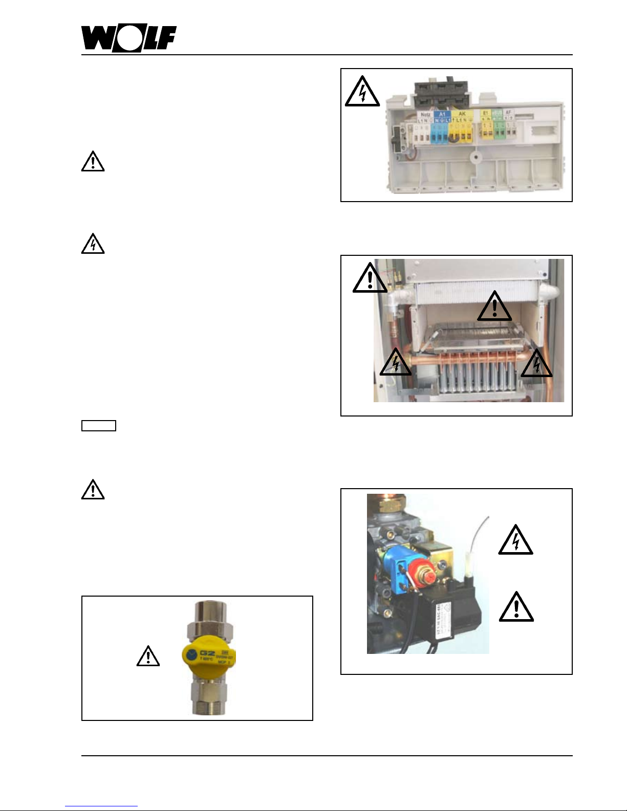
D a n g e r t h r o u g h ' l i v e ' e l e c t r i c al
components.
Please note: Switch OFF the ON / OFF
switch before removing the casing.
Never touch electrical components or
contacts when the ON / OFF switch is in
the ON position. This results in a risk of
electrocution that poses a danger of injury
or death.
The main supply terminals are 'live' even
when the ON / OFF switch is in the OFF
position.
Fig.: Terminal box: Danger from electric current
Fig.: Gas connection: Escaping gas may cause poisoning
or the risk of explosion
Fig.: Ignition transformer, high voltage ignition electrode,
combustion chamber
Risk through 'live' electrical components, risk of burning
through hot components
Fig.: Gas combination valve:
Danger from electric current
Escaping gas may cause poisoning or the risk of
explosion
Balanced flue operated gas bo i l er s
must only be installed in a room that
complies with the appropriate ventilation
requirements. Otherwise there is a risk
of asphyxiation or poisoning. Read these
installation and maintenance instructions
before installing the boiler. Also take the
technical guide into consideration.
Safety instructions / Standards and regulations
Page 4

4
3062347_0309
Safety instructions / Standards and regulations
Please follow these safety instructions closely to prevent accidents and material
losses.
Commissioning - Commissioning must only be carried out by the system installer or a
commissioning engineer designated by him. All actual values must be
recorded in a commissioning/service report that should be kept with these
instructions.
Safety regulations - Observe all national safety regulations and installation requirements.
- Installation, commissioning, inspection, maintenance and repairs must
only be carried out by a competent person (heating engineer / installation
contractor).
- Before working on the equipment / heating system, switch OFF the power
supply (e.g. by removing a separate mains fuse or by means of a main
electrical isolator) and safeguard against unauthorised reconnection.
- Disconnect the system by means of an appliance that isolates all non-earthed
conductors simultaneously with at least 3 mm contact separation.
- It is not permitted to carry out repairs on parts that full a safety function.
- Use only original WOLF replacement parts or those that are equivalent and
that have been approved by the manufacturer.
Instructing the
system user
- The system installer must hand the operating instructions to the system user
and instruct them in the operation of the system.
Only use propane compliant with local regulations, otherwise
faults may arise with the starting characteristics and operation
of the wall mounted gas red boiler; this in turn, may lead to
boiler damage and risk of injury.
Poorly vented LPG tanks can lead to ignition problems. In such
cases, contact your local LPG supplier.
Note: Please read these instructions carefully before the installation
and keep them in a safe place. Please also note the technical
information in the appendix.
Any damage or loss resulting from technical modications to
the control unit or to the control components are excluded from
our liability.
Incorrect use can lead to a risk to life and limb or to a risk of
material losses.
Obtain the permission of your gas supply utility, the ue gas inspector
and the lower water authority [where appropriate] prior to the installation
of Wolf gas red boilers.
Page 5

5
3062347_0309
Safety instructions / Standards and regulations
Standards and regulations
Category: II2ELL3P<DE> and
II2H3P<AT>
NOx class: 5
Efciency: *** star rating according
to 92/42/CEE) for
balanced ue operation
Flue types: CGG-2:
C12x, C32x, C42x, C52, B32
CGU-2:
B11BS
Operating mode: open / balanced ue
To be connected to: chimney, ue chimney /
balanced ue system
- Obtain the permission of your mains gas supplier
and all relevant authorities prior to the installation of
Wolf gas red combi boilers.
- Open ue gas red boilers must only be installed
in a room that complies with the appropriate
ventilation requirements.
The gas red boiler meets with the following regulations
EC Directives
- 2006/95/EC Low Voltage Directive
- 2004/108/EC EMC Directive
- 90/396/EEC Gas user equipment
- 92/42/EEC Efciency directive
DIN / EN Standards
- EN 297; EN298; EN 483; EN 625;
EN 55014-2; EN 60335-1; EN 60335-2-102;
EN 60529; EN 61000-3-2; EN 61000-4-3
The following regulations, rules and guidelines must
be observed during installation:
- Boiler room guidelines or Building Regulations
relating to the construction and installation of
central boiler rooms and fuel storage facilities
- Technical regulations for gas and DHW installations
DVGW-TRGI 1996 and TRF 1996
(in the currently applicable form)
DIN / EN Standards
- EN 437 Test gases; test pressures;
appliance categories
- DIN EN 1283 Procedure for calculating the
standard heating load
- DIN EN 12828 Heating systems in buildings
- DIN EN 1717 Protection of DHW against
contaminations in DHW
installations
- DIN EN 50156-1 (VDE 0116 part 1)
Electrical equipment for
combustion systems
- On site regulatio ns from building and indust ry
regulatory agencies (mainly covered by the emission
test switch)
- On site regulations from the gas supply utility
Page 6
6
3062347_0309
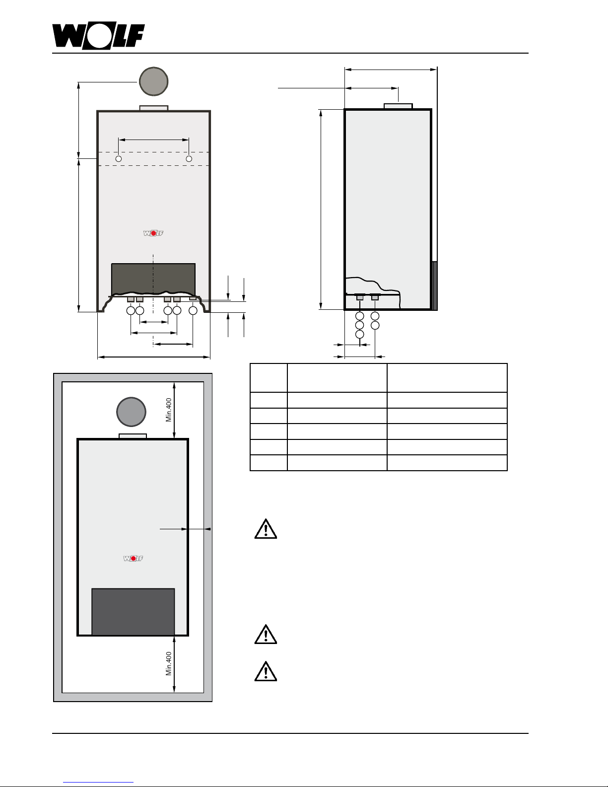
440
Dimensions
Gas red combi
boilers
Gas red boilers
1 Heating ow Heating ow
2 DHW DHW ow
3 Cold water DHW return
4 Heating return Heating return
5 Gas connection Gas connection
Installation inside a cupboard
For installation of the gas red boiler inside a cupboard
note the following:
Never install the gas red boiler on the back wall
of the cupboard, as it may not be substantial
enough to take the boiler's weight. This would
create the risk of water and gas leaks which in
turn would result in a risk of explosion
and ooding.
- Removing the rear wall of the cupboard
Minimum lateral clearance between the gas red boiler
and the cupboard sides 25 mm.
A cutout of 410 x 550 mm is required in the
cupboard top. Otherwise there is a risk of
suffocation and poisoning
With open ue gas red boilers the
ventilation grill in the cupboard door must
be installed with a free minimum diameter
of 600 cm
2
Otherwise there is a risk of suffocation
and poisoning
3
1
2
4
5
3
1
2
4
5
Min.400
Min.400
>25
694
366 CGU-2(K) 18
380 CGU-2(K) 24
258 CGG-2(K) 18/24
344
120
176
170
39
49
855
393
190
226
(CGG-2)
(CGU-2)
73
134
Page 7
7
3062347_0309
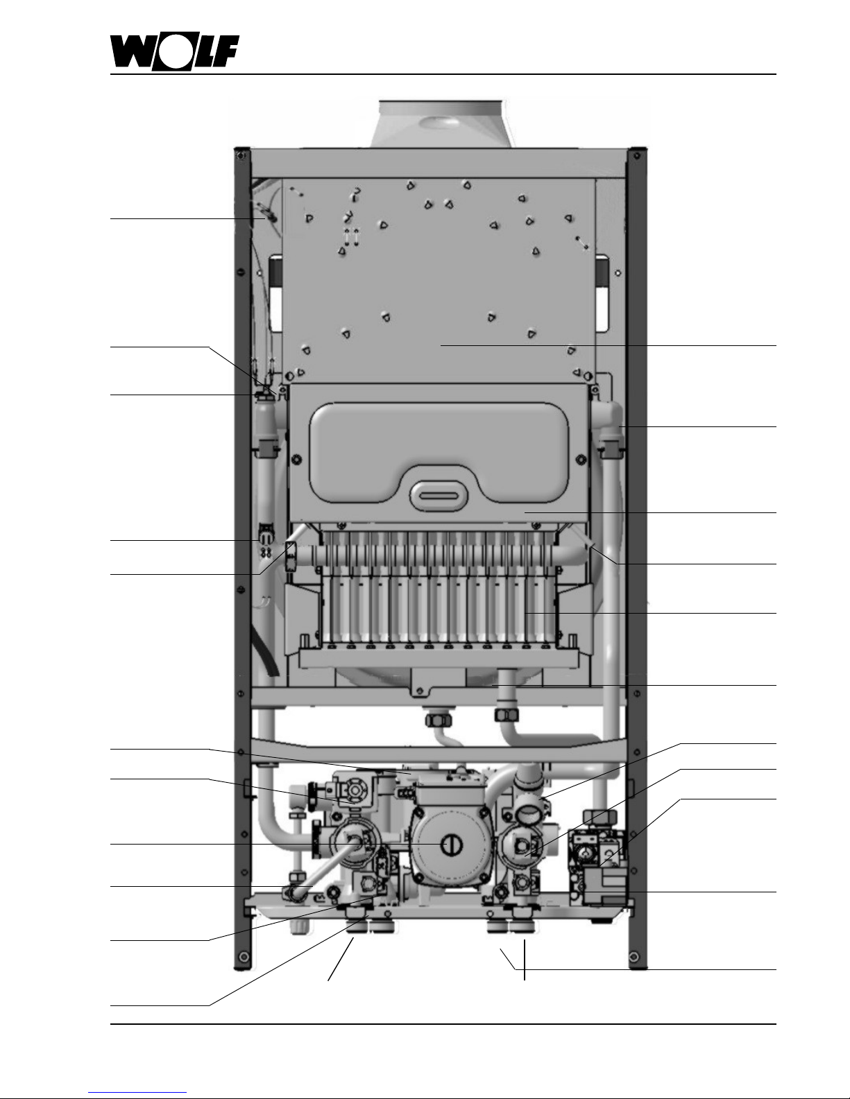
Layout CGU-2(K) 18/24
Combustion
chamber
Internal lling
equipment (optional)
not <DE><AT>
Gas combination
valve
Expansion vessel
Three-way
diverter valve
Flow sensor 2
Limit thermostat
Monitoring
electrode
Ignition electrode
Heating water heat
exchanger
Safety valve
Drain valve
DHW
Flow & temperature
sensor
Flow sensor 1
Draught hood
Gas burner
Heating circuit
strainer
Cold water strainer
with throughput
limiter
Heating circuit
pump
Air vent
Bypass
Flue gas
temperature limiter
HZ - VL
HZ - RL
Page 8
8
3062347_0309
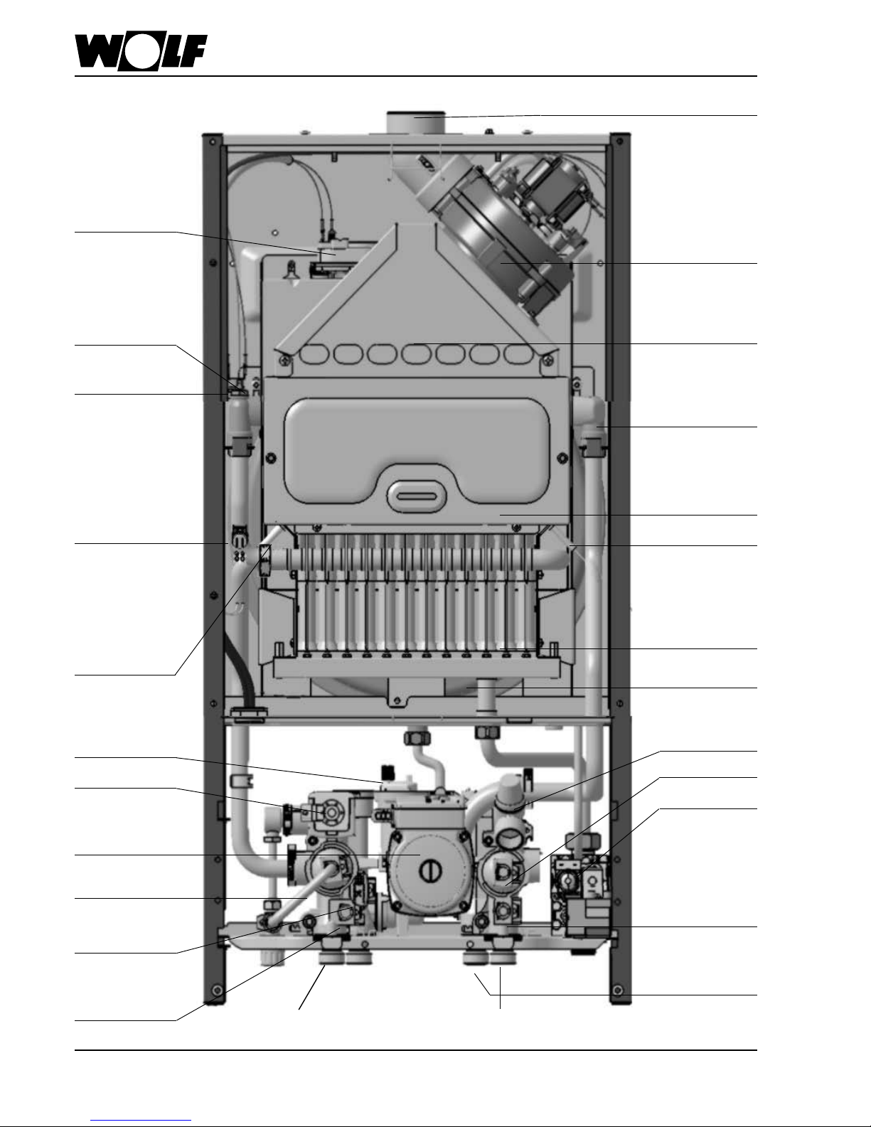
Layout CGG-2(K) 18/24
Flue gas fan
with speed
regulation
Combustion
chamber
Internal lling
equipment (optional)
not <DE><AT>
Gas combination
valve
Expansion vessel
Three-way
diverter valve
Flow sensor 2
Limit thermostat
LAF connection
Monitoring
electrode
Ignition
electrode
Heating water heat
exchanger
Differential
pressure switch
Safety valve
Drain valve
DHW
Flow & temperature
sensor
Flow sensor 1
Flue gas
collector
box
Gas burner
Heating circuit
strainer
Cold water strainer
with throughput
limiter
Heating circuit
pump
Air vent
Bypass
HZ - VL
HZ - RL
Page 9
9
3062347_0309
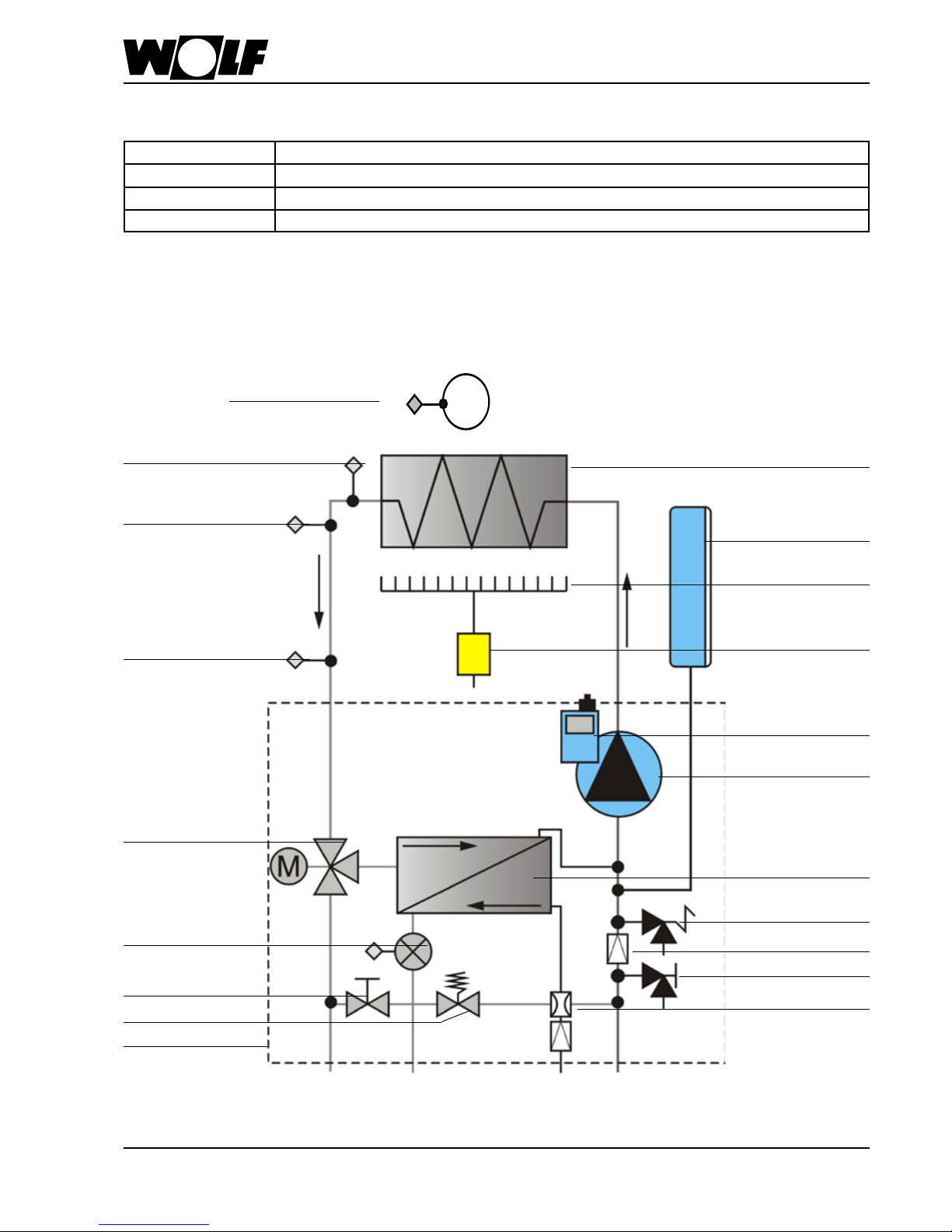
Layout / Equipment code
Heating water heat
exchanger
Gas burner
Gas
combination
valve
Expansion vessel
Air vent
Heating circuit
pump
DHW heat
exchanger
Safety valve
Drain valve
Heating circuit strainer
Cold water strainer with
throughput limiter
Limit thermostat
ow
Flow sensor 2
Flow sensor 1
Three-way
diverter valve
DHW ow
& temperature sensor
(only combi boilers)
Bypass valve
Hydro Tec system
(integrated
components)
Overow valve
Flue gas
temperature limiter
Wolf Low NOx unit with hydro tec system (plug-in technology for quick installation)
compactly designed for low emissions, high energy efciency.
DHW heat exchanger and DHW ow temperature sensor
only with combi boilers
CGU-2 - 18/24 Open ue gas red boiler with integrated cylinder connection
CGU-2 K - 18/24 Open ue gas red combi boiler
CGG-2 - 18/24 Balanced ue gas red boiler with integrated cylinder connection
CGG-2 K - 18/24 Balanced ue gas red combi boiler
Equipment codes
Page 10

10
3062347_0309
Balanced ue gas red boilers must only
be installed in a room that complies with
the appropriate ventilation requirements.
Otherwise there is a risk of asphyxiation
or poisoning. Read these installation and
operating instructions before installing
the gas red boiler. Also take the technical
guide into consideration.
Sound insulation:
Under certain critical installation conditions
(e.g. installation on a drywall) additional
measures may be necessary to soundproof
the boiler. In this case use soundproof
plugs and, if necessary, rubber buffers or
insulation strips.
Positioning information /
Installation dimensions
l.h. turnbuckle
r.h. turnbuckle
Fig.: Opening the turnbuckle
- Determine the installation location for the gas red
boiler; maintain the specied minimum clearances
(see dimensions).
- Fit the supplied installation template (paper poster) to
the wall.
- Transfer the xing hole and connection positions
marked on the installation template to the wall (e.g.
with a power drill).
- Remove the installation template.
- Drill Ø 12 mm holes for the mounting bracket and
secure the bracket using the rawl plugs and screws
supplied. (Before securing the bracket, check that the
rawl plugs are suitable for the wall construction.)
- Remove the casing lid of the gas red boiler. For this,
pivot the control unit lid down, hook in the r.h. and
l.h. turnbuckle, undo the bottom of the casing lid and
unhook at the top.
- Hang the gas red boiler with the hook-in brace on the
back of the boiler onto the mounting bracket.
General
The gas red boiler may only be installed in rooms that
are protected from frost.
During the boiler installation ensure that all
xings are sufciently strong to carry its weight.
Also consider the wall consistency, otherwise
gas or water may escape which could lead to
explosions and ooding. It can also lead to
noise developing.
During the boiler installation, ensure that
no contaminants (e.g. drilling swarf) enter
the gas red boiler otherwise faults may
develop.
The combustion air supplied to the boiler must
be free from chemicals, e.g. uoride, chlorine
or sulphur. Such materials are contained in
sprays, solvents and cleaning agents. Under
the most unfavourable conditions, these
may lead to corrosion, even in the ue gas
system.
Note
500
25 25
(CGU-2-18) Ø110
(CGU-2-24) Ø130
(CGU-2) min.400
(CGG-2)
min.200
(CGG-2-18)
Ø100
1212
344
min.200
1478
Page 11
11
3062347_0309
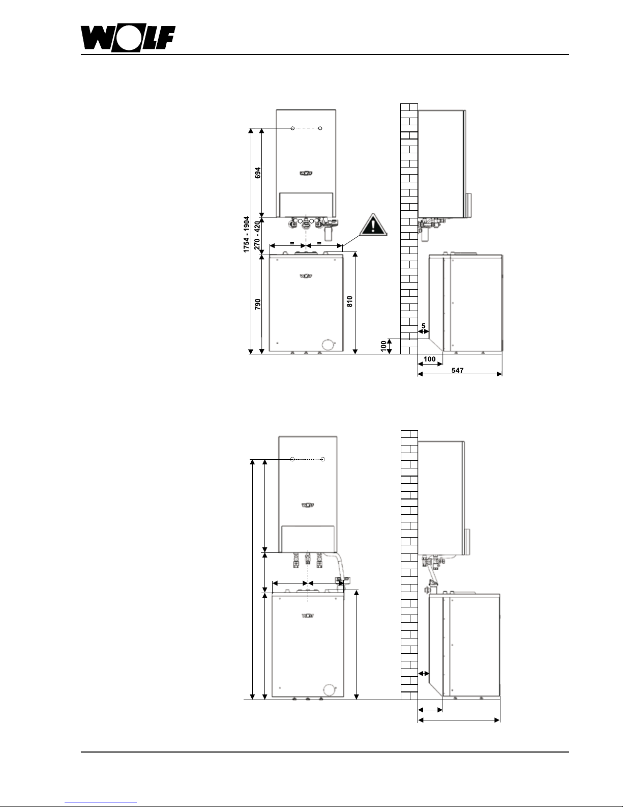
Positioning information /
Installation dimensions
270-420
790
694
1754-1904
810
5
=
=
100
547
Installation dimensions of the boiler with freestanding cylinder SW-120 / CSW-120
Installation on unnished walls
Installation dimensions of the boiler with freestanding cylinder SW-120 / CSW-120
Installation on nished walls
Page 12
12
3062347_0309
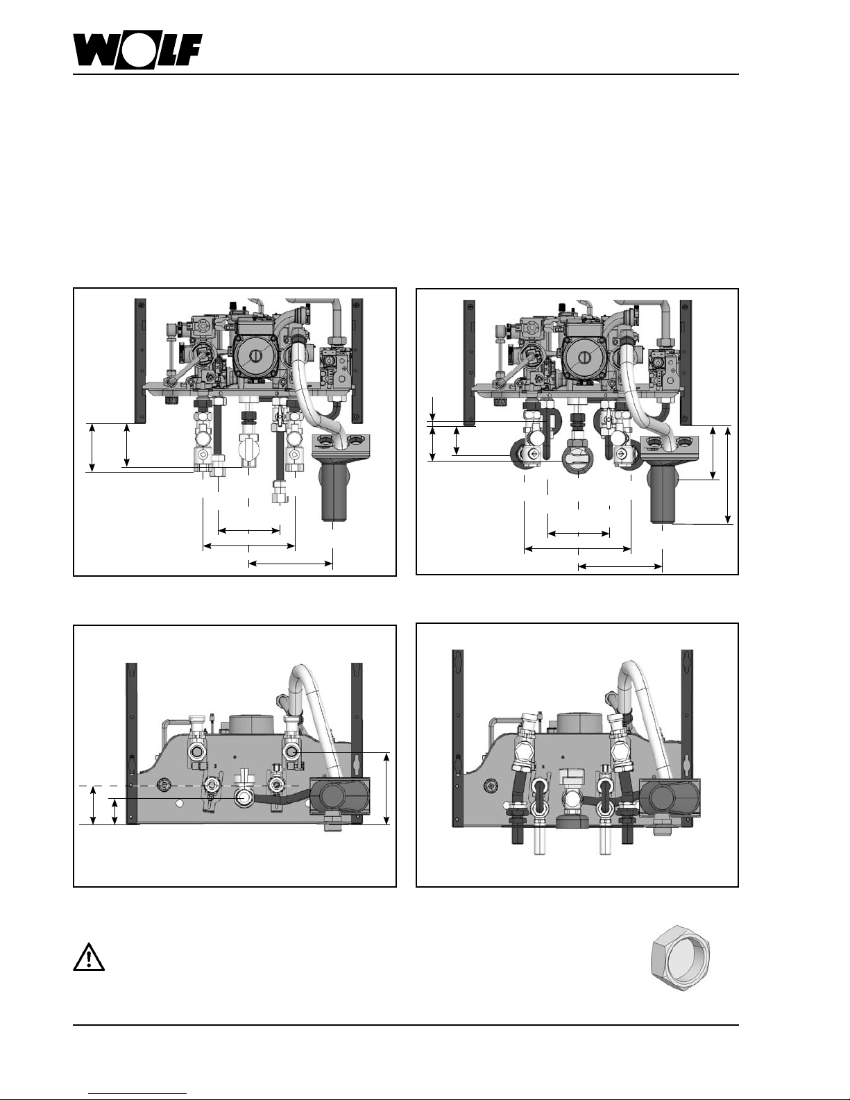
Installation on nished / unnished walls
Fig.: View from below, connection set for installation on
nished walls
Installation on unnished walls (accessory)
Fig.: Front view, connection set for installation on unnished walls
Fig.: View from below, connection set for installation on
unnished walls
Installation on nished walls (accessory)
Fig.: Front view, connection set for installation on nished walls
Heating ow Rp ¾"
DHW Rp ¾" (gas combi boilers)
Cold water Rp ¾" (gas combi boilers)
Heating return Rp ¾"
Gas connection Rp ½"
Drain for safety valve R 1"
With boilers that are not used for DHW, seal the cold and DHW connections with locking
cap G ¾" (accessory).
If this is not done then the building and equipment may be damaged through uncontrolled
water leakages.
Heating ow R ¾"
DHW R ¾" (gas combi boilers)
Cold water R ¾" (gas combi boilers)
Heating return R ¾"
Gas connection R ¾"
Drain for safety valve R 1"
164
94
84
120
176
164
64
55
120
200
7
190
107
73
55
134
Page 13
13
3062347_0309
General boiler installation
Gas connection
Laying the gas pipe, as well as making the
gas connections, must only be carried out by
a licensed gas tter. Close the gas ball valve
on the gas red combi boiler to pressure test
the gas pipe.
Remove all residues from the heating pipework
and the gas pipe prior to connecting the gas
red boiler, particularly in older systems.
Prior to commissioning, test all pipe and gas
connections for leaks.
Inappropriate installation or using unsuitable
components or assemblies may lead to gas
escaping, which results in a risk of poisoning
and explosion.
The gas valve can be subj ecte d to a
maximum pressure of 150 mbar. Higher
pressure may dam age the gas valve,
resulting in a risk of explosion, asphyxiation
or poisoning. Close the gas ball valve on
the gas red boiler to pressure test the
gas pipe.
Install a tested and certified pressure
reducer, if the cold water supply pressure is
above the maximum permissible operating
pressure of 10 bar. Otherwise water could
escape resulting in a risk of ooding.
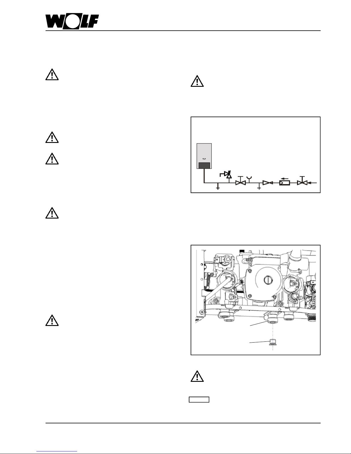
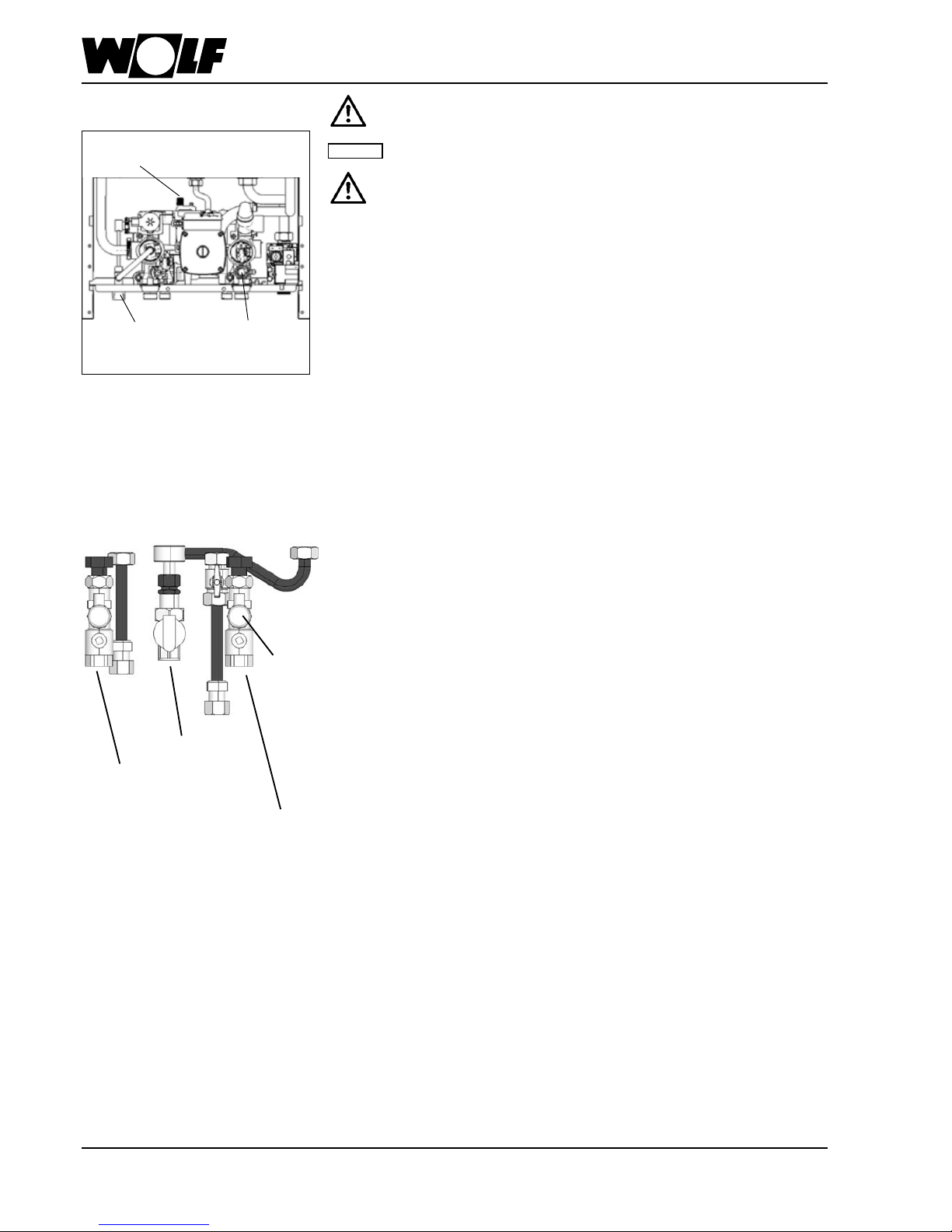
Fig.: Cold water connection
Cold water and DHW connection
For the cold water and DHW connection, we recommend
installation in accordance with the diagram below.
- Wolf connection sets (accessories) are available for
installation on nished and un nished walls. The
connection pipes are Cu 18x1.
Hydraulic connections
Note:
As standard, a combined cold water strainer
with throughput controller is tted at the cold
water connection of the boiler (see Fig.).
Fig.: Throughput controller with cold water strainer
Installation inside a cupboard
For installation of the gas red boiler inside a
cupboard note the following:
Never install the gas red boiler on the back wall
of the cupboard, as it may not be substantial
enough to take the boiler's weight. This would
create the risk of water and gas leaks which
in turn would result in a risk of explosion and
ooding.
Removing the rear wall of the cupboard
Minimum lateral clearance between the gas
red boiler and the cupboard sides 25 mm.
A cutout of 410 x 550 mm is required in the
cupboard top. Otherwise there is a risk of
suffocation and poisoning
With open ue gas red boilers the
ventilation grille in the cupboard door must
be installed with a free minimum diameter of
600 cm2.
Otherwise there is a risk of suffocation and
poisoning.
As the cold water strainer may need
to be cleaned, provide a facility for its
removal in site.
Otherwise there is a risk of faults.
Drain
Drain
Shut-off valve
Pressure
reducing valve
Shut-off valve
Cold water inlet
Pressure gauge port
DHW lter
Safety valve
Note
Page 14
14
3062347_0309
Electrical connection
CGU-2(K) / CGG-2(K)
General notes
The installation must be carried out by a
licensed electrical contractor. Observe
the regulations of the relevant authorities
and the local regulations of the power
supply company.
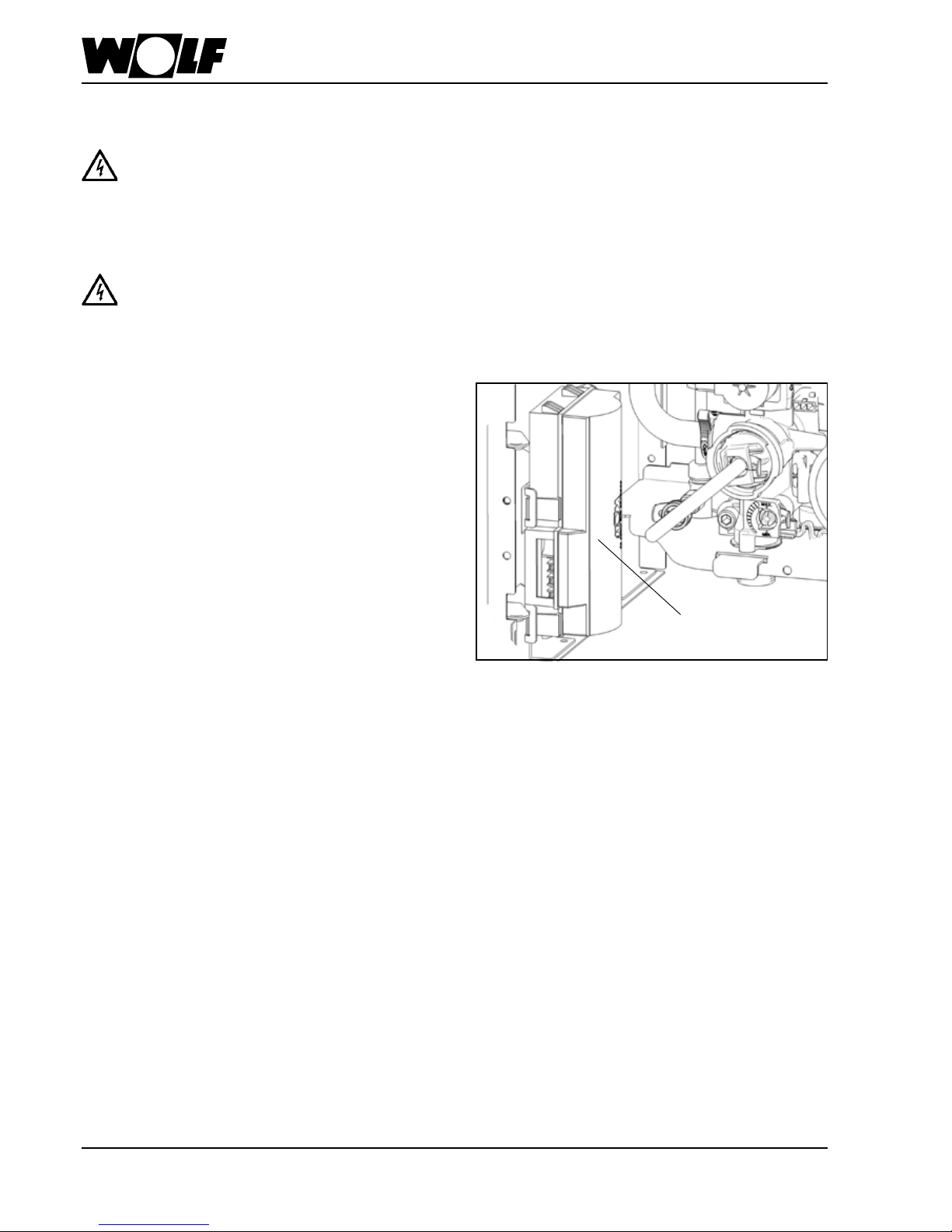
The power supply terminals are 'live'
even when the ON/OFF switch has been
switched OFF.
Terminal box
Terminal box
The control, regulating and safety equipment are fully
wired and tested.
You only need to connect the power supply and the
external accessories.
Power supply connection
Connect the power supply permanently or with a safety
plug (no plug connection in protective areas 1 and 2, i.e.
near a bath or shower).
Provide the power supply via a mains isolator (e.g. fuse,
heating system emergency stop), which ensures at least
3 mm contact separation for all poles.
Connection cable exible, 3 x 1.0 mm² or rigid,
max. 3 x 1.5 mm².
The plug must be accessible when using a power supply
cable with safety plug. Flexible power supply cable
3 x 1.0 mm².
Page 15
15
3062347_0309
Flue gas damper connection (230 V; max.200 VA)
Insert the cable glands into the terminal box. Insert
and secure the connecting cable through the cable
gland. Connect the connecting cable to terminals L1, N,
and .
Fig.: Flue gas damper connection
Changing a fuse
Isolate the boiler from the main supply prior
to changing a fuse. The ON/OFF switch on
the boiler does not provide separation from
the power supply.
Danger through 'live' electrical components.
Never touch electrical components or
contacts if the boiler has not been isolated
from the power supply. Danger of death.
Fig.: Pivot the control unit forward, terminal box
cover open
Fuse
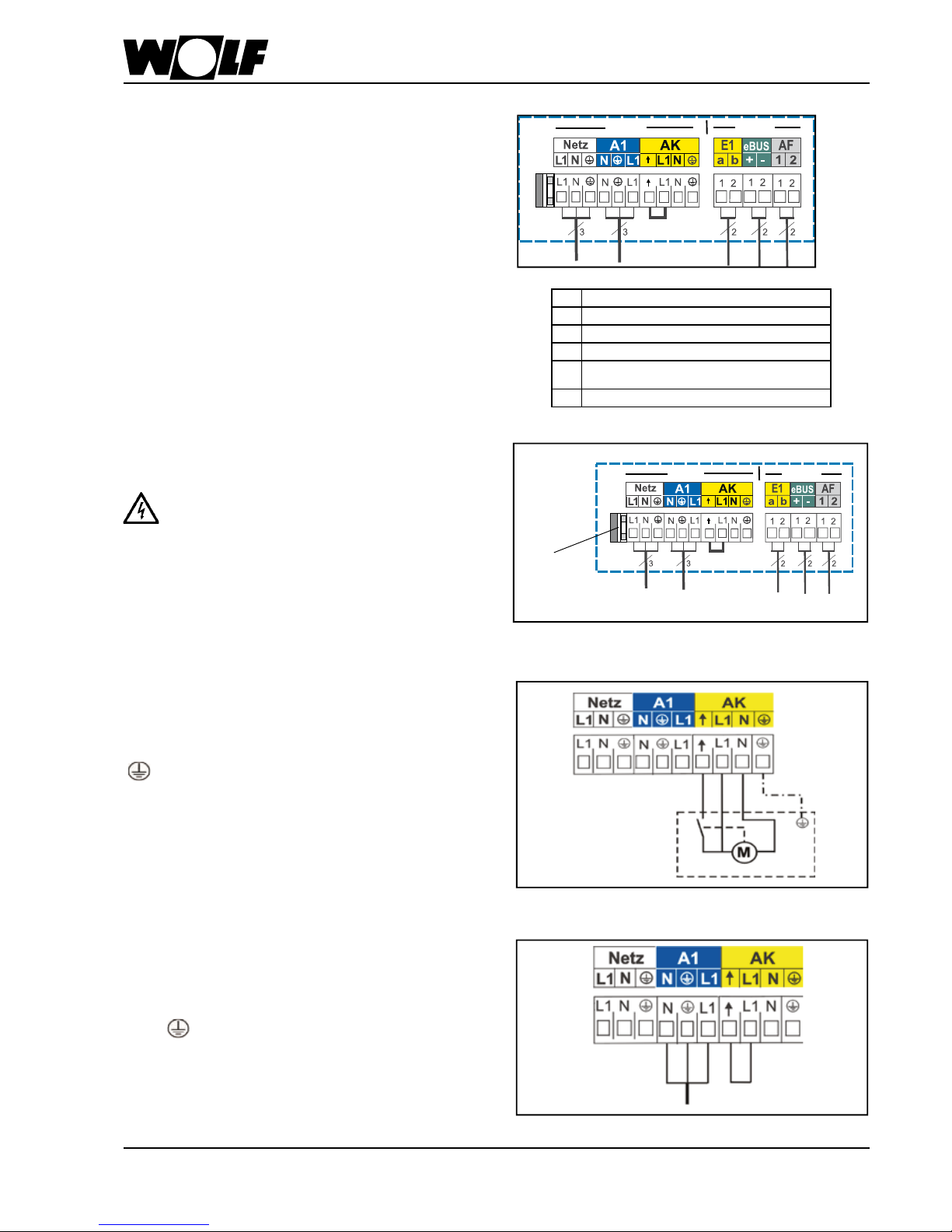
Electrical connection CGU-2(K)
Connection to Output A1 (230 VAC; max.200 VA)
Insert the cable glands into the terminal box. Insert
and secure the connecting cable through the cable
gland. Connect the connecting cable to terminals L1,
N and .
Fig.: Connection output A1
Installation information, electrical connection
- Isolate the system from the power supply before
opening the casing.
- Pivot the control unit to the side.
- Open the terminal box.
- Insert the strain relief into the holes provided.
- Strip approx. 70 mm off the power supply cable
insulation.
- Push the cable through the strain relief and
secure the strain relief.
- Pull the Rast-5 plug.
- Terminate the appropriate cores at the Rast-5 plug.
- Push the inserts back into the terminal box casing.
- Push the Rast-5 plugs back into the correct
positions.
A
Mains connection 230 VAC/50 Hz
C
Programmable output A1
G
Flue gas damper connection
D
Programmable input E1 zero volt
E
2-wire eBUS connection, digital Wolf control
accessories
F
Outside temperature sensor
A C G D E F
.
230 V < 24 V
230 V < 24 V
Page 16
16
3062347_0309
Electrical connection CGU-2(K)
Fig.: Connection DHW circulation pump / external
accessories
Changing a fuse
Isolate the boiler from the main supply prior
to changing a fuse. The ON/OFF switch on
the boiler does not provide separation from
the power supply.
Danger through 'live' electrical components.
Never touch electrical components or
contacts if the boiler has not been isolated
from the power supply. Danger of death.
Fig.: Pivot the control unit forward, terminal box
cover open
Fuse
Connection to Output A1 (230 VAC; max. 200 VA)
Insert the cable glands into the terminal box. Insert
and secure the connecting cable through the cable
gland. Connect the connecting cable to terminals L1,
N and .
Fig.: Connection output A1
Installation information, electrical connection
- Isolate the system from the power supply before
opening the casing.
- Pivot the control unit to the side.
- Open the terminal box.
- Insert the strain relief into the holes provided.
- Strip approx. 70 mm off the power supply cable
insulation.
- Push the cable through the strain relief and
secure the strain relief.
- Pull the Rast-5 plug.
- Terminate the appropriate cores at the Rast-5 plug.
- Push the inserts back into the terminal box casing.
- Push the Rast-5 plugs back into the correct
positions.
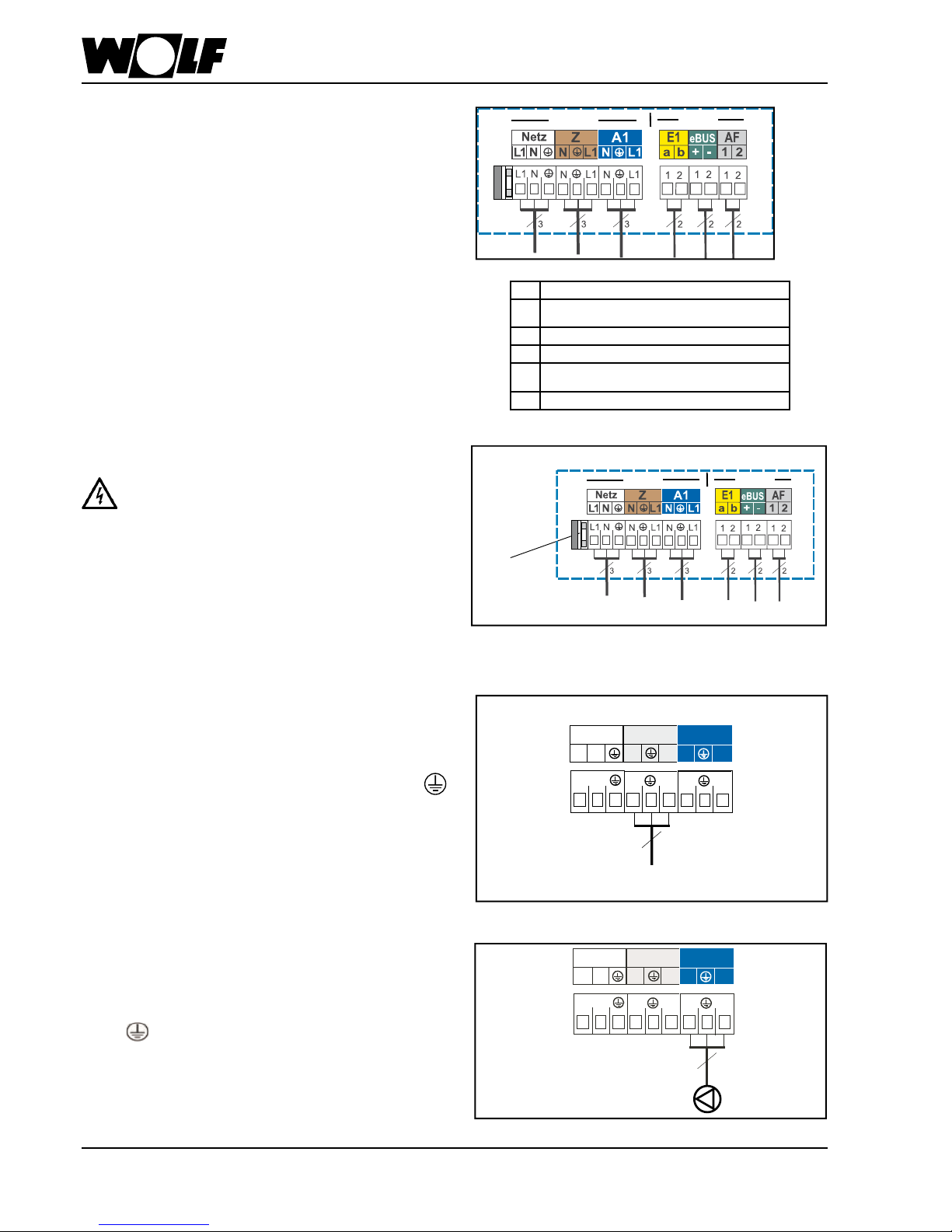
Power supply for external accessories
(230 VAC; max. 200 VA)
Insert the cable glands into the terminal box. Insert and
secure the connecting cable through the cable gland.
Connect the connecting cable to terminals L1, N and .
Netz
Z
A1
N
N
N
L1
L1
L1
L1
L1
L1
N
N
N
3
Z
A1
N
N
NL1
L1
L1
L1 L1
L1
NN
N
3
Netz
A
Mains connection 230 VAC/50 Hz
B
Power supply, ext. Accessories
230 VAC/50 Hz/max. 200 VA
C
Programmable output A1
D
programmable input E1 zero volt
E
2-wire eBUS
connection, digital Wolf control accessories
F
Outside temperature sensor
A B C D E F
230 V < 24 V
230 V < 24 V
Page 17
17
3062347_0309
Connection, analogue outside temperature sensor
The analogue outside temperature sensor for digital
control accessory (e.g. BM) may be connected to the
terminal strip of the gas red boiler at the connection AF
or the terminal strip of the BM.
Fig.: Connection, analogue outside temperature sensor
Connection of digital Wolf control accessories
(e.g. BM, MM, SM1, SM2, KM)
Only connect control units from the Wolf accessory
range. Eac h accessory is supplied with its own
connection diagram.
Use a 2-core cable (cross-section > 0.5 mm²) as the
connecting cable between the control unit accessory
and the gas red boiler.
Fig.: Digital Wolf control accessories connection (eBUS
interface)
Electrical connection
CGU-2(K) CGG-2(K)
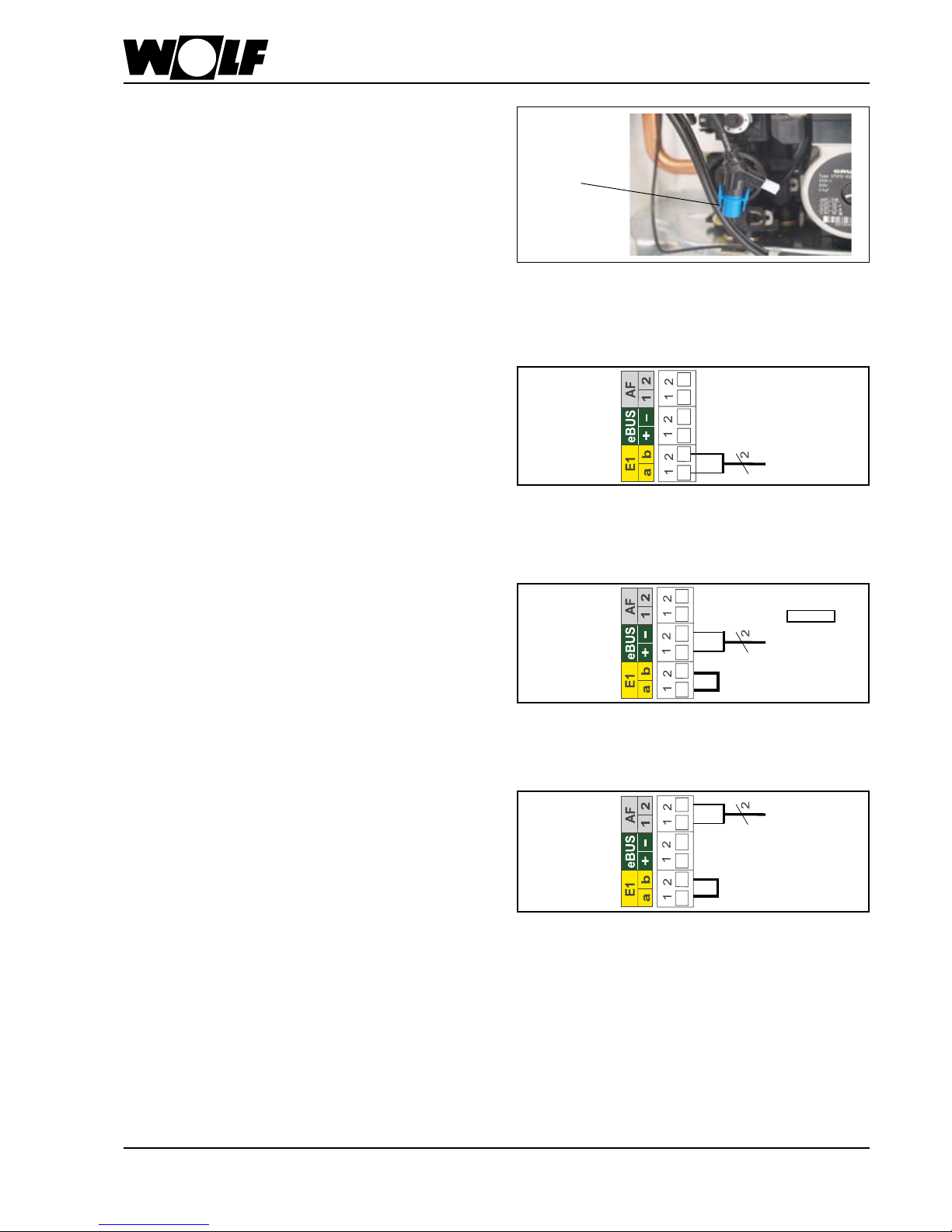
Fig.: Connection, programmable input
Connection, programmable input E1 (<24 V)
Connect the connecting cable for input 1 at terminals E1
in accordance with the wiring diagram; rst remove the
jumper between a and b from the respective terminals.
The functions of input E1 can only be scanned and
adjusted with Wolf control accessories with eBUS
capability.
DHW tank sensor connection
- When a cylinder is to be connected, the blue socket
of the cylinder sensor must be connected to the blue
plug of the control unit.
- Observe the cylinder installation instructions.
Fig.: Blue plug, cylinder sensor connection
Blue plug
Note
Pay attention
+ , to polarity
Page 18
18
3062347_0309
Fill / vent the system
Procedure for boilers with
internal lling facility
not for <DE> <AT>
- Fill the entire heating system and boiler via the lling facility or an on-site
ll & drain valve up to approx. 0.5 - 1 bar, whilst simultaneously venting the
heating system.
- Close the shut-off valves on the heating water side of the boiler (ow and
return).
- Push the drain hose onto the drain valve of the hydraulic assembly.
- Clean the heat exchanger by opening the internal lling facility and the
drain valve simultaneously on the hydraulic assembly (make sure there is
no air remaining in the heat exchanger).
Procedure for boilers without
internal lling facility
Filling the system
Fill the system and vent it thoroughly to safeguard the perfect
function of the gas red boiler.
Otherwise there is a risk of faults.
The heating water must not be mixed with inhibitors or antifreeze;
otherwise leaks and ooding could result.
- Close the gas ball valve.
- Before connecting the gas red boiler to the heating system, ush the entire
system to remove residues such as welding pearls, hemp, putty, etc. from
the pipework and to remove air that may have collected.
- Fill the DHW system of the boiler until water ows out of a DHW draw-off point.
- To ll the heating system use the ll & drain connections. Open the cap of the
automatic air vent valve on the heating circuit pump by approx. 2 revolutions, but
do not remove the cap.
- Open all radiator valves and the shut-off valves on the heating water side of the
boiler.
- Fill the entire heating system and boiler via the ll & drain valves (Wolf
accessory) up to approx. 0.5 bar, whilst simultaneously venting the heating
system.
- Close the return shut-off valve on the heating water side of the boiler.
- Attach drain hose to the drain valve on the hydraulic assembly (alternative, if only
a ll & drain connection is provided).
- Clean the heat exchanger by opening the ll & drain valve and/or the
drain valve simultaneously on the hydraulic assembly
(make sure there is no air remaining in the heat exchanger).
- Remove the drain hose and open the boiler shut-off valve(s) on the heating water
side again.
- After venting, raise the system pressure to 2.5 bar.
- Start the boiler, set the heating water temperature selector to position "2"
(pump running, illuminated signal ring (status display) constantly green).
- Vent the pump; for this, briey open and then retighten the air vent
screw, optimum venting in pump stage 3.
Top up with water when the system pressure falls severely.
- Open the gas shut-off valve. Press the reset button.
- When in constant use the heating circuit vents automatically via the heating
circuit pump, venting optimum at pump stage 3. After venting set to pump
stage 1 or 2 for reduced noise, depending on customer preference.
- At system pressure below 1.0 bar the boiler may experience faults.
If necessary ll on heating side.
Internal lling
facility not for
<DE><AT>
Drain
valve
Fig.: Shut off valves (accessory)
Gas shut-off valve
Heating ow
(incl. ll & drain
connection)
Heating return
(incl. ll & drain
connection)
Automatic
air-vent valve
Fill & drain
Connection
Note
Page 19

19
3062347_0309
- Instruct the customer about energy-saving options.Saving energy
Commissioning guidelines
Only qualied personnel must carry out the commissioning and initial
start-up of the boiler as well as instruct the user.
Guidelines for commissioning
- Flush and vent boiler (use shut-off valve with ll & drain valve from Wolf
accessory range), ll boiler and system and test for tightness. Normal
operating pressure when system is cold 1.5 bar. Prevent water leaks.
- Check location and seating of the installation.
- Check the gas supply pressure.
- Check all connections and component links for leaks.
- If tightness cannot be ensured then there is a danger of water damage.
- Check that all ue gas accessories have been correctly installed.
- Open the water and shut-off valves on ow and return.
- Open gas connection.
- Switch ON emergency heating switch and switch ON the ON/OFF switch on
the control unit.
- Check the adjustment of the ue length, resetting if required.
See chapter "Adjusting the ue length".
- Check the ignition and ame structure of the burner.
- The illuminated ring shows a yellow colour, if the boiler starts correctly.
- Instruct the customer in the operation of the boiler, with the aid of the
installation instructions.
- Complete the commissioning report and hand over the instructions to the
customer.
- Implement the "Installation" and "Electrical connection" of the boiler
and all extension and programming modules in accordance with the
instructions in the associated manuals.
Step 1
Step 2
Step 3
Step 4
Step 5
Step 6
Step 7
Step 8
Step 9
Step 10
Step 11
Step 12
Step 13
Step 14
Step 15
Note
Otherwise there is a risk of faults.
e
e
e
e
e
e
e
e
e
e
e
e
e
e
e
Page 20
20
3062347_0309
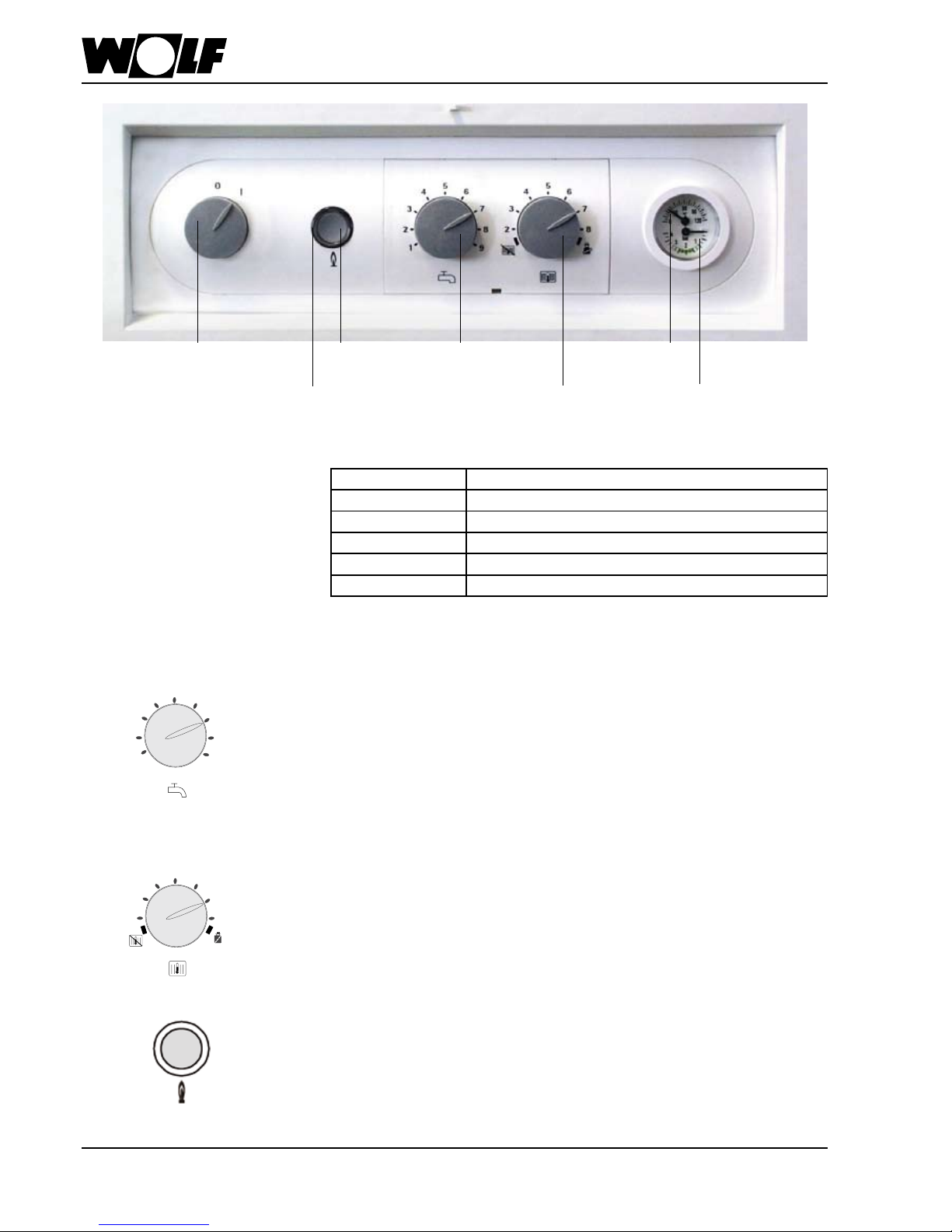
Control / Function / Commissioning
ON / OFF switch
DHW
temperature
selector
Pressure
gauge
Reset
button
Heating water
temperature
selector
Illuminated
signal ring
Thermometer
9
1
2
8
3
7
4
6
5
DHW temperature selector
Settings 1-9 correspond with a DHW temperature of 40-65 °C with gas combi
boilers, or 15-65 °C with gas boilers with a cylinder. Combined with a control
thermostat for wall mounted gas red boilers, the adjustment at the DHW
temperature selector is disabled; instead the temperature is selected at the
boiler control thermostat.
2
8
3
7
4
6
5
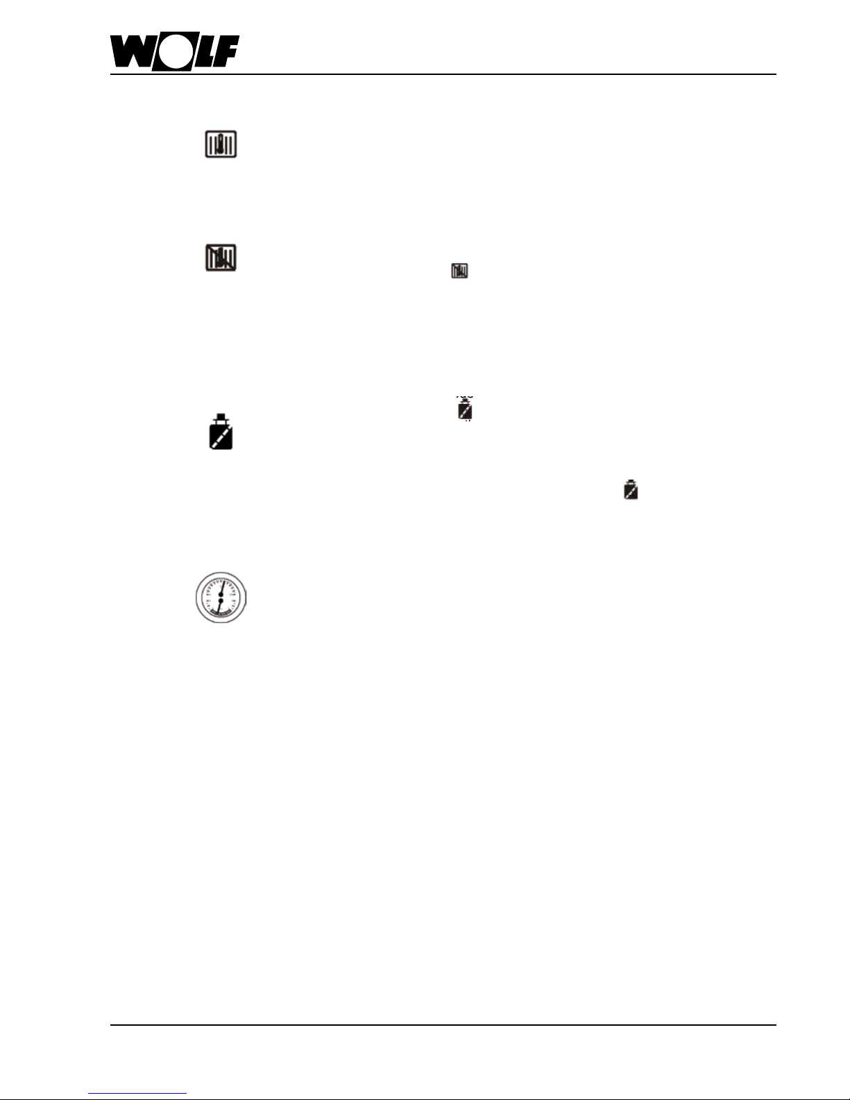
Heating water temperature selector
Settings 2-8 correspond to a heating water temperature of 40-80 °C. Combined
with a temperature controller for wall mounted gas red boilers, the adjustment
at the heating water thermostat is disabled; instead the temperature is selected
at the boiler temperature controller.
Signal ring as
status display
Display Explanation
Flashing green Standby (power supply ON, burner OFF)
Constant green light Heat demand: pump running, burner OFF
Flashing yellow Emissions test mode
Constant yellow light
Burner ON, ame steady
Flashing red
Fault
Reset
A fault is reset by pressing the reset button which will also restart the system.
Pressing the reset button reactivates the system, if there was no fault.
Page 21
21
3062347_0309
In conjunction with the accessory controllers BM / AWT / ART, the settings at
the boiler relating to DHW and heating water are disabled.
Note:
Setting
Winter mode (position 2 to 8)
In winter mode, the boiler heats to the temperature selected at the heating water
temperature controller. According to the pump operating mode, the circulation
pump operates constantly (factory setting) or only in parallel with the burner
activation / run-on period.
Summer mode
The winter mode is deactivated by rotating the heating water temperature
selector into position . In other words, the boiler will then operate in summer
mode. Summer mode (heating OFF) means, only DHW heating. Frost protection
for the heating system and pump anti-seizing protection, however, remain
enabled.
In summer mode, the circulation pump operates for approx. 30 seconds after
a maximum idle period of 24 hours.
Anti-seizing pump protection
Thermomanometer
The current heating water temperature is displayed in the upper area.
The water pressure in the heating system is displayed in the lower area. In
normal use, the water pressure should be between 2.0-2.5 bar.
Emissions test mode
The emissions test mode is activated by rotating the heating water temperature
selector into position . The signal ring ashes yellow. After the emissions
test mode has been activated, the boiler will heat with the selected maximum
heating output. Any previous cycle block will be cancelled. The emissions test
mode terminates after 15 minutes or when the maximum ow temperature has
been exceeded. For a renewed activation, turn the heating water temperature
selector anti-clockwise and then back into position .
Control / Function / Commissioning
Page 22

22
3062347_0309
Parameter overview / setting report
Column 1 settings apply to control accessories ART, AWT
Column 2 settings apply to Wolf control system with BM programming module
(Setting and function of the most important functions on the following pages, further description,
see BM installation instructions.)
Parameters Setting range
Factory setting
Individual settings
Column 1 Column 2
HG00 Adjusting ue lengths 1 to 5 4
GB05 A09 Frost protection limit -20 to +10 °C +2 °C
GB01 HG01 Burner switching differential 5 to 25 K 8 K
HG02 Lower burner output heating 1 to 100% 1%
HG03 Upper burner output DHW 1 to 100% 100%
GB04 HG04 Upper burner output heating 1 to 100% 100%
GB06 HG06 Pump operating mode 0 to 2 0
GB07 HG07 Boiler circuit pump run-on time 0 to 30 min 1 min
GB08 HG08 Maximum boiler temperature, heating 40 to 90 °C 80 °C
GB09 HG09 Burner cycle block 1 to 30 min 7 min
HG10 eBUS address (display only) 1 to 4 1
HG11 DHW quick start temperature 10 to 60 °C 10 °C
HG12 Gas type, 1=natural gas 0=LPG 0 to 1 1
HG13 Programmable input E1 1 to 11 1
HG14 Programmable output A1 0 to 15 6
HG15 Cylinder hysteresis 1 to 30 K 5 K
HG20 Max. cylinder heating time 0 to 5 h 2 h
HG21
Minimum boiler water temperature TK-min >40 °C*
20 to 60 °C 40 °C
HG23 Maximum DHW temperature 60 to 80 °C 65 °C
HG25
Boiler overtemperature during DHW cylinder heating
0 to 40 K 20 K
HG70
Manifold sensor (display only)
HG80-89 Fault history
The control parameters can only be modied or displayed via Wolf control accessories with eBUS
capability. For installation and procedures, check the operating instructions of the relevant accessories.
To prevent damage to the heating
system, cancel night setback when
outside temperatures fall below -12 °C. If
this rule is not observed, ice may form on
the ue outlet which may cause injury to
individuals or material losses.
Modications must only be carried out by
a recognised heating contractor or by the
Wolf customer service.
L.h. rotary selector
Program selection
Display R.h. rotary selector
Temperature selection
Info key Single cylinder
heating key
Setback keyHeating key
Note
BM programming module
Displaying / modifying control parameters
with Wolf control accessories
* To prevent damage to the boiler TK min must be set > 40 °C
Page 23

23
3062347_0309
Press the r.h. rotary selector to change to control level 2. Turn the r.h. rotary
selector clockwise to select the menu level Contractor and con rm the selection
by pressing the r.h. rotary selector again.
The display shows the code scan.
Contractor level
expert
The correct code is set by pressing (display indication ashes) and then
turning the r.h. rotary selector from 0 to 1. After changing the code from 0 to
1, pressing the r.h. rotary selector again con rms the setting; you are then at
the Contractor level.
Code scan
code-NO
- - - -
Factory setting: 1
The boiler circuit pump operates constantly if the outside temperature stays
below the selected value. The burner starts and heats the boiler to at least
TK-min., if the boiler water temperature falls below +5 °C.
Note:
Only change the factory setting if you can ensure that the heating system and
its components will not freeze up at low outside temperatures.
Frost protection limit
Parameter A09
A09
2.0
Factory setting: 2 °C
Setting range: -20 to +10 °C
Note
Incorrect operation can lead to system faults.
Please note when adjusting parameter A09 (frost protection / outside
temperature), that frost protection is no longer safeguarded if you set
temperatures lower than 0 °C. This can lead to heating system damage.
Displaying / modifying control parameters
with Wolf control accessories
The control parameter should be
set according to the table opposite,
subject to the calculated length of the
balanced ue routing. The calculated
length will be rounded up or down
accordingly.
(Also see chapter "Adjusting the ue
length".)
Matching the pipe length
Parameter HG00
HG00
4
Factory setting: 4
Setting range: 1 to 5
HG00
Adjusting
pipe lengths
Calculated length (m)
1 1.3 - 1.5
2 1.5 - 2.5
3 2.5 - 3.5
4
(factory setting)
3.5 - 4.0
5 4.0 - 5.0
The burner switching differential regulates the burner temperature within a set
range by switching the burner ON and OFF.
The higher the ON / OFF temperature differential, the higher the boiler
temperature uctuation around the set temperature.
Burner switching differential
Parameter HG01
HG01
8
Factory setting: 8 K
Setting range: 5 to 25 K
The lower burner output in heating mode can be adjusted within the modulation
range. The setting relates to the maximum heating output in kW (see table
"Limiting maximum heating output").
Lower burner output Hz
Parameter HG02
HG02
1
Factory setting: 1
Setting range: 1 to 100
Page 24

24
3062347_0309
J
J
J
Displaying / modifying control parameters
with Wolf control accessories
The higher burner output in DHW mode can be adjusted within the modulation
range. The setting relates to the maximum heating output in kW (see table
"Limiting maximum heating output").
Upper burner output DHW
Parameter HG03
HG03
100
Factory setting: 100
Setting range: 1 to 100
The higher burner output in heating mode can be adjusted within the modulation
range. The setting relates to the maximum heating output in kW (see table
"Limiting maximum heating output").
Upper burner output Hz
Parameter HG04
HG04
100
Factory setting: 100
Setting range: 1 to 100
Pump operating mode 0:
Heating circuit pump for heating systems without cascade control and
without low loss header
The boiler pump runs constantly when there is a heat demand. When the heat
has been switched off via the room thermostat or remote control, the boiler
pump runs for the set time (pump run-on Hz, parameter HG07).
Pump operating mode
Parameter HG06
HG06
0
Factory setting: 0
Setting range: 0 / 1 / 2
Pump operating mode 1:
Feed pump for heating systems with cascade control and/or low loss
header/buffer (manifold sensor essential)
Boiler pump becomes the feed pump.
The manifold sensor affects the heating operation as well as the cylinder heating
(please note: only cylinder mode possible). The boiler pump will not run for a
general heat demand, but rather only when there is a burner demand in the
heating operation, with pump run-on according to parameter HG07.
VL Sensor 1
Three-way valve
Header
Manifold sensor E1
VL Sensor 2
A1 as heating
circuit pump
A1 as primary
cylinder pump
DHW cylinder
Hydraulic scheme:
Gas red boiler
Boiler
pump
or
Page 25

25
3062347_0309
Subject to there being no heat demand from the heating circuits, the boiler
circuit pump will run-on in accordance with the set time, to prevent a boiler
safety shutdown at high temperatures.
Boiler circuit pump run-on time
Parameter HG07
HG07
1
Factory setting: 1 min
Setting range: 0 to 30 min
Displaying / modifying control parameters
with Wolf control accessories
J
J
J
J
Hydraulic scheme:
VL Sensor 2
VL Sensor 1
Three-way valve
Manifold
sensor E1
A1 as heating
circuit pump
Cylinder
sensor
Buffer
DHW cylinder
Gas red boiler
Boiler
pump
Pump operating mode 2:
Buffer cylinder primary pump
Boiler pump becomes the buffer primary pump.
The manifold sensor (buffer) only affects the heating operation. In case of DHW
heating, the reference temperature is provided by the internal boiler sensor.
The boiler pump will not run for a general heat demand, but rather only when
there is a burner demand in the heating operation, with pump run-on according
to pump run-on time.
With DHW demand (free standing cylinder, combi boiler, strati cation cylinder)
the heating circuit pump runs according to function.
Operation without manifold sensor:
Boiler pump only during burner operation; regulated by internal sensor.
This function limits the boiler water temperature upwards in heating mode, and
the burner shuts down. This parameter has no function during cylinder heating,
and the boiler water temperature may also be higher during this time. "Reheating
effects" can result in the temperature being exceeded a little.
Maximum limit
Boiler circuit TV-max.
Parameter HG08
HG08
80
Factory setting: 80 °C
Setting range: 40 to 90 °C
Page 26

26
3062347_0309
The eBUS address can only be displayed here. The setting is done as described
in "Conversion/eBUS address in cascade operation" and is only required in
cascade operation with several boilers.
eBUS address
Parameter HG10
HG10
1
Factory setting: 1
Setting range: 1 to 4
Gas type set according to the following table:
1 = Natural gas
0 = LPG
The modulating current for the gas combi valve is adjusted to t with the
relevant setting.
The conversion of the gas type can also be carried out through the selector or the
heating temperature selector (see control settings after gas type conversion).
Gas type
Parameter HG12
HG12
1
Factory setting: 1
Setting range: 0 to 1
Outside of the DHW switching times (in the control accessories) and in summer
mode, water can be heated to and kept at a certain temperature in the at-plate
heat exchanger.
10 °C = DHW quick start disabled
40-60 °C = DHW quick start enabled
DHW Quick Start
Parameter HG11
HG11
10
Factory setting: 10 K
Setting range: 40 to 60 K
Displaying / modifying control parameters
with Wolf control accessories
Each time the burner is shut down in heating mode, it will be blocked for the
duration of the burner cycle block.
The burner cycle block is reset by switching the ON / OFF switch OFF and ON
or by brie y pressing the reset button.
Burner cycle block
Parameter HG09
HG09
7
Factory setting: 7 min
Setting range: 1 to 30 min
Page 27

27
3062347_0309
Explanation
1
Room thermostat
Closed contact is a pre-requisite to enable the burner in heating mode.
No function (blocked) for DHW mode. No function (blocked) for emissions test mode and frost protection, no error message.
Open contact blocks the enabling of the heating and the boiler pump (pump run-on time)
2
Maximum thermostat / system pressure switch
Closed contact is a prerequisite for enabling burner in central heating, DHW and emissions test mode. When the
contact is opened the boiler switches off and the pump run-on begins.
A fault message is generated.
5
Ventilation damper
Function monitoring of the ventilation damper with zero volt contact
Closed contact is a prerequisite for enabling burner in central heating, DHW and emissions test mode
Output A1 must be programmed to 7, ventilation damper function
6
DHW circulation pushbutton
After the DHW circulation pushbutton is activated, output A1 is switched on for 5 minutes, if output A1 is programmed as
DHW circulation pump (A1 = 13)
7
Manifold sensor
A manifold sensor (5 K-NTC) is connected at E1. The ow temperature control in heating and DHW mode (pump
operating mode 1) or only in heating mode (pump operating mode 2) no longer relates to the ow sensor but rather the
manifold sensor. Safety functions and emissions test mode remain at the ow sensors. In case of break or short circuit
of the manifold sensor, the ow sensor takes on the temperature control. Observe parameter HG 06
8
Burner block (BOB)
Operation without burner
Closed contact, burner blocked
Heating circuit pump and cylinder primary pump run in normal operation
In emissions test mode and frost protection the burner is enabled
Open contact enables the burner again
10
External burner demand
Closed contact, set FT is set to TKmax ow hysteresis
Demand also functions in standby; cycle block active
(Control of output A1 when parameter output A1 = 14)
0, 3, 4, 9, 11 are without function
The functions of input E1 can only be scanned and adjusted with Wolf control
accessories with eBUS capability.
The following functions can be allocated to input E1:
Programmable
Input E1
Parameter HG13
HG13
1
Factory setting: 1
Setting range: 1 to 10
Displaying / modifying control parameters
with Wolf control accessories
The electrical control to input E1 must be made with a zero volt contact. Otherwise,
use an on-site relay for potential separation.
Page 28

28
3062347_0309
Explanation
0 No function
Output A1 is not enabled
1 DHW circulation pump 100%
Output A1 is switched by control accessories (BM), if DHW circulation has been enabled. Output A1 is constantly
enabled when no accessory controller is installed.
2 DHW circulation pump 50%
Output A1 is switched by control accessories (BM), if DHW circulation has been enabled. 5 minutes ON and 5
minutes OFF. Output A1 constantly cycled in 5 minute cycles when no accessory controller is installed.
3 DHW circulation pump 20%
Output A1 is switched by control accessories (BM), if DHW circulation has been enabled. 2 minutes ON and 8
minutes OFF. Output A1 cycles constantly when no accessory controller is installed.
4 Alarm output
Output A1 is controlled after a fault and expiry of 4 minutes.
5 Flame detector
Output A1 is controlled after a ame has been recognised.
6 Cylinder primary pump
Output A1 always closes along with the boiler pump in DHW operation. Both with 3-way valve idle period protection
and with pump kick.
7 Ventilation damper
Output A1 is activated before each burner start. The burner will, however, only be enabled after input E1 has been
closed.
Important: In any case, input E1 must also be programmed as "Ventilation damper"!
Otherwise there is a risk of faults.
The feedback to input E1 must be made with a zero volt contact. Otherwise, use an on-site relay for potential
separation.
8 External ventilation
Output A1 is controlled inverted to the burner. Switching OFF external ventilation (e.g. extractor fan) during burner
operation is only required, if the boiler is operated as open ue system.
9 External LPG valve
Output A1 switches with the gas combi valve
10 Direct heating circuit pump
Pump switches in accordance with the enabling of the direct heating circuit
11 External pump
Output A1 switches synchronously with the heating circuit pump (HKP). Use with, for example, system separation.
12 Diverter valve
If E1 is programmed for burner blocking (option 8) and closed, A1 switches ON. If E1 is not programmed as burner
blocking, A1 always stays OFF.
13 DHW circulation pump
DHW circulation pump ON for 5 mins, if input E1 is programmed as DHW circulation pushbutton and input E1 Key is
closed.
14 Pump with external burner demand
Synchronous control with input E1 (E1 = 10, ext. burner demand)
15 Constant voltage for accessories
A1 is always closed (constant voltage 230 VAC)
The functions of output A1 can only be scanned and adjusted with Wolf control
accessories with eBUS capability.
The following functions can be allocated to output A1:
Programmable
Output A1
Parameter HG14
HG14
6
Factory setting: 6
Setting range: 0 to 15
Displaying / modifying control parameters
with Wolf control accessories
Note
230 V AC
< 24 V
Page 29

29
3062347_0309
The cylinder hysteresis regulates the start point for cylinder heating. The greater
the hysteresis, the lower the start temperature.
Example: Set cylinder temperature 60 °C
Cylinder hysteresis 5 K
Cylinder heating commences at 55 °C and ends at 60 °C.
Cylinder hysteresis
Parameter HG15
HG15
5
Factory setting: 5 K
Setting range: 1 to 30 K
Cylinder heating commences as soon as the cylinder temperature sensor
demands heat. The heating circuit pump would be constantly switched OFF, if
the boiler was undersized, the cylinder was scaled-up or if DHW was constantly
drawn. The accommodation cools down signi cantly. One option enables a max.
cylinder heating time to be speci ed to limit this effect. The control unit reverts
to heating mode, when the set cylinder heating time has expired and cycles in
the selected rhythm between heating and cylinder heating mode, irrespective
of whether the cylinder has reached its set temperature or not.
Set this parameter to 0 in heating systems with a high DHW consumption, e.g.
hotels, sports facilities etc.
Max. cylinder heating time
Parameter HG20
Factory setting: 2 h
Setting range: 0 to 5 h
HG20
2
The control unit is equipped with an electronic boiler thermostat, with an
adjustable minimum switch-ON temperature. The burner is switched ON subject
to the cycle block if this temperature is not achieved when heat is demanded.
The minimum boiler water temperature TK-min. is also not necessarily achieved
when there is no heat demand.
Minimum boiler water temperature
TK-min.
Parameter HG21
HG21
40
Factory setting: 40 °C
Setting range: 20 to 60 °C
Displaying / modifying control parameters
with Wolf control accessories
This temperature can be enabled at 80 °C, if for commercial reasons a higher
DHW temperature is required.
If pasteurisation (BM) has been enabled, the DHW cylinder will be heated to
65 °C during the rst cylinder heating of the day, subject to parameter HG23
being set to this temperature or higher.
Take adequate measures to prevent scalding.
Maximum DHW temperature
Parameter HG23
HG23
65
Factory setting: 65 °C
Setting range: 60 to 80 °C
Note
Page 30

30
3062347_0309
The excess temperature differential between the cylinder temperature and the
boiler water temperature during cylinder heating is selected with parameter
HG25. This ensures that, even in spring and autumn, the boiler water
temperature is higher than the cylinder temperature, thereby ensuring short
heating times.
Boiler overtemperature during
DHW cylinder heating
Parameter HG25
HG25
20
Factory setting: 20 K
Setting range: 0 to 40 K
Displaying / modifying control parameters
with Wolf control accessories
Parameters
HG 80
Fault 1
HG 81
Fault 2
HG 82
Fault 3
HG 83
Fault 4
HG 84
Fault 5
HG 85
Fault 6
HG 86
Fault 7
HG 87
Fault 8
HG 88
Fault 9
HG 89
Fault 10
HG70
54
Display only:
With parameter HG70 analogue input E1 is displayed, if a manifold sensor is
connected (display only).
HG80
04
Display only:
Fault history
Parameter HG80
Page 31

31
3062347_0309
Reset
Observe the following steps to implement a reset:
- The operating mode switch must be set to O (OFF).
- Press the reset button on the control unit and hold it down.
- Switch on ON/OFF switch in I position.
- After 5 seconds the signal ring will illuminate and ash yellow/green and
red every 1 second.
- Then release the reset button again.
All parameters (individual settings) are returned to their factory
settings by a reset, except for gas type settings and adjustments
to pipe lengths.
ON / OFF switch
Press reset button
With boilers CGU-2 / CGG-2 there are 3 possible boiler versions.
The DHW circuit is bridged and is not used
When drawing DHW the ow rate sensor
recognises the DHW demand. The burner is
red-up and regulated to the set DHW outlet
temperature (adjusted via rotary selector or
control accessories)
When drawing DHW, the temperature
falls below the set DHW temperature. The
burner res up and regulates the boiler ow
temperature and boiler excess temperature
when preparing DHW
DHW connection versions /
Resetting control unit
Boiler
Combination
boiler
Boiler with cylinder
A VL sensor 2
B VL sensor 1
C Boiler pump
D Three-way valve
E Flow rate sensor
F Cylinder sensor
Legend
Note
A
B
C
D
A
B
C
D
E
F
A
B
C
D
Page 32

32
3062347_0309
Boiler in cascade
operation
eBUS address
Position
Rotary
selector, DHW
temperature
selection
Illuminated ring
display
1 (factory setting) 1 1 ashing red
2 2 2 ashing yellow
3 3 3 ashing yellow/red
4 4 4 ashing yellow/green
ON / OFF switch
DHW temperature
selector
Pressure
gauge
Reset
button
Heating water
temperature
selector
Illuminated
signal ring
Thermometer
- At the system ON / OFF switch, switch the boiler rst OFF and then ON again. There must not be any fault
present at the boiler.
- Press reset button for between 30 and 60 seconds after turning on the mains and keep pressed down during
the next step. Setting the address is only possible during this time window.
- After 10 seconds the illuminated signal ring indicates the currently selected gas type (see table: eBUS address).
- Turn the DHW temperature selector towards the required address and check the setting by means of the colour
of the illuminated signal ring.
- The adjustment will only be activated when the reset button is released.
- A successful setting of the eBus address is indicated by a triple ashing yellow/red (0.4 s ON / 1.0 s OFF) of the
signal ring.
Setting the eBUS address
for cascade mode
When operating several boilers (up to 4 control units) in conjunction with a cascade controller KM, adjust
the eBUS address of the boilers in accordance with the table, below.
Table: eBUS address
Page 33

33
3062347_0309
Start-up gas connection
Only qualied personnel must carry out the
commissioning and boiler operation as well
as the user instruction to prevent dangers
and injuries as well as material losses.
- The boiler and system must be fully vented and must
be absolutely tight.
- If the system water pressure falls below 1.5 bar, top
up with water until a pressure of 1.5 to max. 2.5 bar
has been achieved.
- Check that all ue gas accessories have been correctly
installed.
- The gas red boiler must be switched OFF. Open the
gas shut-off valve.
- Remove the casing cover.
- Release the plug at test nipple and vent the gas
supply pipe.
Check test nipple for gas-tightness,
otherwise gas may esc ape, resulting
in a risk of explosion, asphyxiation or
poisoning.
Prior to commissioning, ensure that the boiler corresponds
to the gas type available.
Gas type Wobbe index Ws
kWh/m³ MJ/m³
Natural gas H 11.4 - 15.2 40.9 - 54.7
LPG P 20.3 - 21.3 72.9 - 76.8
Commissioning gas train:
- Pull the hose off and tighten the test nipple again.
- Retighten the plug.
- Start the boiler.
- Check the ignition and the regular ame structure of
the burner.
Never take the boiler into use if the actual value falls
outside the specied limits.
→ Notify gas supply utility.
Gas type Nominal supply pressure,
Permissible range
Natural gas H 20 mbar 18 - 25 mbar
LPG P 50 mbar 43 - 57 mbar
LPG P 37 mbar 25 - 45 mbar
LPG P 29 mbar 25 - 35 mbar
- Connect the hose to the pressure test appliance at
test nipple and check against atmosphere.
- Read off value and enter in the commissioning
report.
Page 34

34
3062347_0309
- Continue with adjusting of the control unit subject to gas type
- Adjusting the nozzle pressure
- Identication
1. Nozzle change:
- Switch OFF the boiler at the ON/OFF switch and
isolate it from the power supply
- Remove the casing lid of the gas red boiler. For this,
pivot the control unit lid down, hook in the r.h. and l.h.
turnbuckle, undo the lower casing lid and unhook at
the top
- Close the gas valve, observe all safety instructions
and crack open the gas ttings at the gas manifold
- Remove xing screw
- Pull out the gas manifold
- Undo all burner nozzles (spanner size 7) at the gas
manifold
- Insert new burner nozzles with new gaskets
- Reassemble the boiler in reverse order
Table: Number of nozzles, nozzle size
Boiler No. of nozzles Natural gas H LPG/propane
Nozzle ID Nozzle
Ø mm
Nozzle ID Nozzle
Ø mm
CGU-2(K) 18 090 0.90 060 0.60
CGU-2(K) 24 090 0.90 060 0.60
CGG-2(K) 18 087 0.87 057 0.57
CGG-2(K) 24 087 0.87 057 0.57
Conversion to other gas types
CGU-2(K) / CGG-2(K)
Fixing screws
Gas tting
Gas manifold
The conversion to other gas types is made in four steps:
1. Nozzle replacement
2. Adjusting the control unit after converting the gas type
3. Checking and adjusting the nozzle pressure
4.
Identication
Note
Carry out all steps, otherwise there is a risk of
incorrect functions or system damage.
Page 35

35
3062347_0309
Control unit settings after
gas type conversion
ON / OFF switch
DHW temperature
selector
Pressure
gauge
Reset
button
Heating water
temperature
selector
Illuminated
signal ring
Thermometer
- At the system ON / OFF switch, switch the boiler rst OFF and then ON again. There must not be any fault
present at the boiler.
- Press the reset button within the following 30 seconds and hold it down during the next steps.
- On (CGU) after 5 seconds the currently set gas type is displayed at the signal ring,
see table: Setting gas type.
On (CGG) after 5 seconds the currently set pipe length is displayed at the signal ring.
- Turn the heating water temperature selector towards the required gas type and check the setting by means of
the colour of the illuminated signal ring (see table adjusting the gas type).
- The adjustment will only be activated when the reset button is released.
- A successful conversion of the gas type is indicated by a triple ashing yellow/red (0.4 s ON / 1.0 s OFF) of the
signal ring.
Table: Adjusting the gas type
2. Adjusting the control unit:
Check the nozzle pressure after converting the gas type, otherwise material losses and
incorrect functions can occur.
Gas type Natural gas LPG
Illuminated ring display quickly ashing yellow quickly ashing red
Heating water temperature adjustment
l.h. closing r.h. end stop
Note: The adjustment of the gas type can also be done with the BM accessory controller
(Contractor parameter HG12, description see chapter
"Displaying / modifying control parameters with Wolf control accessories").
Note
Page 36

36
3062347_0309
Check nozzle pressure
3. Checking and adjusting the nozzle pressure:
- The gas red boiler must be switched OFF.
- Open the gas shut-off valve.
- Remove boiler casing cover and move the control unit
to the front.
- Undo the plug at the test nipple [2].
- (+) Connect the differential pressure tester with a hose
at test nipple [2].
- (-) Connect the differential pressure tester with a hose
at test port [3] of the combustion chamber casing (only
CGG-2(K)).
- Start the boiler by turning the heating water temperature
selector to position 8.
- Read off the nozzle pressure P
min
(at minimum boiler
output) within 180 seconds of ignition (soft start phase
= minimum output).
- Turn the heating water temperature selector further to
the emissions test position [chimney symbol].
- Read off the nozzle pressure P
max
(at maximum boiler
output) within the 15 minute test phase.
- Compare the actual values with those in the table.
- Close the plug again.
[2]
[3]
Gas pressures for gas throughput adjustment according to the nozzle pressure method
Table: Nozzle pressure table
Nozzle pressure in mbar (1013 ±0.5 mbar; 15 °C)
Gas red boilers
(gas fired combi
boilers)
Rated output P
in kW
Rated thermal
load
Q in kW
Natural gas H
W
1
= 45.7 MJ/m³
= 12.7 kWh/m³
LPG P
W1= 70.7 MJ/m³
= 19.6 kWh/m³
CGU-2(K) -18 18.0 20.2 12.7 26.7
15.3 17.3 9.5 20.0
13.0 14.8 7.1 14.8
10.9 12.5 5.2 10.7
8.0 8.8 3.2 5.8
CGU-2(K) -24 24.0 26.5 12.9 25.4
20.4 22.5 9.4 18.7
16.0 18.1 6.3 12.3
13.0 14.9 4.4 8.5
10.9 12.0 3.1 6.0
CGG-2(K) -18 18.0 19.7 15.9 36.0
15.3 16.7 11.4 25.9
13.0 14.2 8.8 19.3
10.9 12.0 6.3 14.1
8.0 8.5 3.3 7.5
CGG-2(K) -24 24.0 26.5 16.8 35.8
20.4 22.5 12.2 26.1
16.0 17.7 7.5 15.9
13.0 14.0 4.8 10.0
10.9 11.7 3.4 7.3
Page 37

37
3062347_0309
The gas red boiler corresponds to protection level IP X4D and can be installed in bathrooms in safety zone 1 and
more widely in accordance with VDE 0100 Part 701.
Boiler certication
1)
Balanced ue B32 required
Gas throughput table for gas volume adjustment according to the volume ow method
If the actual values fall outside these limits, readjust the gas valve (see the respective chapter),
otherwise material losses at the boiler and incorrect functions can result.
Otherwise continue under the point "Removing the test equipment again".
Note
Gas volume adjustment check
If the actual net caloric value is known, the gas volume can be checked with a stop watch and a gas meter
according to the following formula:
Gas throughput [l/min] =
Rated thermal load [kW] x 1 000
Net caloric value Hi [kWh/m³] x 60
Check nozzle pressure
Boiler Type Category Operating mode
To be connected to
Open
ue
Open
balanced
ue
Chimney
Air /
ue gas
chimney
Balanced
ue system
CGU-2(K)
B
11BS
II
2H3P
X X
CGG-2(K)
B32, C
12x
,
C
32x
, C
42x
II
2H3P
X
1)
X X
1)
X X
Gas red
boilers
(gas red
combi
boilers)
Thermal
output
kW
Rated
thermal
load
kW
Gas throughput in l/min (1013 mbar; 15 °C)
Natural gas H
with an operational net caloric value of H
i
in MJ/m³ (kWh/m³)
25.9(7. 2) 27.4(7. 6) 28. 8(8.0) 30. 2(8.4) 31. 7(8.8) 33. 1(9.2)
34.6(9. 6)
36.0(10. 0) 37. 4(10.4) 38. 9(10.8)
40.3(11. 2)
equivalent of a gross caloric value of HS in MJ/m³ (kWh/m³)
28.8(8.0) 30.2(8.4) 31.7(8.8) 33.8(9.4) 35.3(9.8) 36.7(10.2) 38.1(10.6) 40.0(11.1) 41.8(11.6) 43.2(12.0) 4.6(12.4)
18.0 20.2 47.0 44.5 42.3 40.3 38.4 36.8 35.2 33.8 32.5 31.3 30.2
15.3 17.2 40.0 37.9 36.0 34.3 32.8 31.3 30.0 28.8 27.7 26.7 25.7
CGU-2(K) -18 13.0 14.8 34.3 32.5 30.8 29.4 28.0 26.8 25.8 24.7 23.7 22.8 22.1
10.9 12.5 28.9 27.4 26.0 24.8 23.7 22.6 21.6 20.9 20.0 19.3 18.6
8.0 8.8 21.3 20.2 19.2 18.3 17.4 16.7 16.0 15.4 14.7 14.2 13.7
24.0 26.5 61.3 58.1 55.2 52.6 50.2 48.0 46.1 44.3 42.4 40.8 39.5
20.4 22.5 52.8 40.0 47.5 45.2 43.2 41.3 39.7 38.0 36.5 35.1 34.0
CGU-2(K) -24 16.0 18.1 41.9 39.7 37.7 35.9 34.3 32.8 31.5 30.2 29.0 27.9 27.0
13.0 14.9 34.5 32.7 31.0 29.6 28.2 27.0 25.9 24.8 23.9 23.0 22.2
10.9 12.0 28.9 27.4 26.0 24.8 23.7 22.6 21.8 20.9 20.0 19.3 18.6
18.0 19.7 45.6 43.5 41.0 39.9 37.3 35.7 34.1 32.8 31.5 30.4 29.3
15.3 16.7 38.6 36.6 34.8 33.1 31.7 30.2 29.0 27.8 26.7 25.8 24.8
CGG-2(K) -18 13.0 14.2 32.8 31.1 29.6 28.2 26.9 25.8 24.8 23.7 22.8 21.9 21.2
10.9 12.0 27.8 26.3 25.0 23.8 22.7 21.8 20.6 20.0 19.3 18.5 17.9
8.0 8.5 19.6 18.6 17.7 16.8 16.1 15.4 14.8 14.2 13.6 13.1 12.7
24.0 26.5 61.3 58.2 55.2 52.6 50.2 48.0 49.0 44.2 42.5 40.9 39.4
20.4 22.5 52.1 49.3 46.9 44.6 42.6 40.8 39.1 37.5 36.6 34.8 33.5
CGG-2(K) -24 16.0 17.7 41.0 38.8 36.9 35.1 33.5 32.1 30.8 29.5 28.4 27.4 26.3
13.0 14.0 32.4 30.7 29.2 27.7 26.5 25.4 24.3 23.3 22.4 21.6 20.9
10.9 11.7 27.0 25.6 24.4 23.2 22.1 21.2 20.3 19.5 18.8 18.1 17.4
Page 38

38
3062347_0309
Readjusting the gas valve:
Carry out the nozzle pressure adjustment in the following
order:
- Remove transparent plastic cap [4] from the gas
combination valve.
- Operate the boiler in emissions test mode (P
max
).
-
Adjust the maximum pressure at nut [5] (spanner size 10).
- Tightening increases the pressure.
- Releasing reduces the pressure.
- Pull the cable from the gas valve. The boiler goes to
minimum output (P
min
).
- Adjust the minimum pressure at screw [6] in accordance
with nozzle pressure table (Philips screwdriver 6x1);
during this adjustment, hold nut [5] tightly.
- Turning right increases the pressure.
- Turning left reduces the pressure.
- Replace the plastic cap [4].
- Reconnect the cable.
[4]
[6]
[5]
4. Identication:
Carry out the re-designation of the gas type in
accordance with the instructions supplied with the
conversion kit.
Remove the test equipment:
Readjust the gas valve
Checking / adjusting the nozzle pressure
- Shut down the boiler. Close the gas shut-off valve.
- Pull the hoses off and retighten the test nipple [2] and
the test port [3]. Open the gas shut-off valve.
Check gas tightness of the test nipple,
otherwise there is a danger of gas escaping
and consequent damage to health.
[2]
Page 39

39
3062347_0309
Flue gas
pipe length
CGG-2(K)
Position
Rotary selector
Temperature
selection
DHW
Illuminated ring
display
(green)
Calculated length
(m)
1
1
1x0.4 s ON/OFF
1x1.5 s pause
1.3 - 1.5
2 2
2x0.4 s ON/OFF
1x1.5 s pause
1.5 - 2.5
3 3
3x0.4 s ON/OFF
1x1.5 s pause
2.5 - 3.5
4*
(factory setting)
4
4x0.4 s ON/OFF
1x1.5 s pause
3.5 - 4.0
5* 5
5x0.4 s ON/OFF
1x1.5 s pause
4.0 - 5.0
ON / OFF switch
DHW temperature
selector
Pressure
gauge
Reset
button
Heating water
temperature
selector
Illuminated
signal ring
Thermometer
- At the system ON / OFF switch, switch the boiler rst OFF and then ON again. There must not be any fault
present at the boiler.
- Press the reset button within the following 30 seconds and hold it down during the next steps.
- After 5 seconds, the illuminated signal ring indicates the currently selected gas type
(see table: Pipe length adjustment).
- Turn the DHW temperature selector towards the required pipe length and check the setting by means of the
ash sequence of the illuminated signal ring.
- The adjustment will only be activated when the reset button is released.
- A successful conversion of the gas type is indicated by a triple ashing green (0.4 s ON / 1.0 s OFF)
of the signal ring.
Adjusting the ue lengths CGG-2(K)
Note: The adjustment of the ue pipe length can also be done with the BM accessory controller
(Contractor parameter HG12, description see chapter
"Displaying / modifying control parameters with Wolf control accessories").
* Operation only with condensate drain pipe in the balanced ue routing (see accessories)
Table: Pipe length adjustment
Page 40

40
3062347_0309
Flue gas test CGU-2(K) / CGG-2(K)
The ue gas emissions must be tested with the boiler
closed.
- Remove the screw from the test port "inlet air".
- Insert the test probe until it bottoms out.
- Start the boiler and turn the heating water temperature
selector to emissions test [chimney sweep symbol].
(The illuminated status display ring ashes yellow).
- Test the temperature and CO
2
or O2 value.
The balanced ue is not gas-tight if the CO2 content
≥ 0.3%; rectify the leak.
- After the test has been completed, switch the boiler
OFF, remove the test probe and close the test port.
Ensure the screws are seated rmly.
Testing the combustion air CGG-2
Vertical boiler ue connection
- Remove the screw from the test port "ue gas".
- Insert the test probe into the centre of the pipe.
- Start the boiler and turn the heating water temperature
selector to emissions test [chimney sweep symbol].
(The illuminated status display ring ashes yellow).
- Test the temperature and CO2 value.
The CO2 value should be tested at maximum heat
output. Take the values from the table on the right.
- After the test has been completed, switch the boiler
OFF, remove the test probe and close the test port.
Ensure the screws are seated rmly.
Testing the ue gas parameter at CGG-2
Flue gas can escape into the installation
room, if the test port is left open. This
results in a risk of asphyxiation.
Horizontal boiler ue connection
Testing the ue gas parameter at CGU-2
- Insert the test probe into the ue pipe and nd the core
ow.
- Record ue gas values.
- Take out the test probe and close test port.
Fig.: Flue gas test CGU-2(K)
Gas type Natural gas H LPG P
CO2 - value in %
8.0 9.3
The CO2 value may deviate by a maximum of ± 1%.
Page 41

41
3062347_0309
Limiting the maximum output
The output setting can be modied with Wolf control accessories with eBUS capability via parameter HG 02, 03, 04.
The heating output will be determined by the modulation current of the gas valve. By reducing the modulation current
in accordance with the table, the maximum output will be matched at 80/60 °C to natural gas H and LPG.
Output [kW]
Modulation current [%]
Output [kW] 10.9 12 15 18 21 24
I
Mod
[%] 0-27 33 46 60 75 100
Output [kW]
Modulation current [%]
Output [kW] 8 10 12 14 16 18
I
Mod
[%] 0-27 39 52 65 77 100
Output adjustment 18 kW
Output adjustment 24 kW
Page 42

42
3062347_0309
Selecting the pump stage / bypass
Fig.: Pump rate stages at the heating circuit pump
Bypass valve
The boiler is equipped with a three-stage pump that is
set to stage 2 in the delivered condition.
The minimum circulation volume is ensured by a
connection line between the ow and return. An
automatic overow valve and a manually adjustable
bypass valve are integrated into the connection line.
In the delivered condition, the bypass valve is fully
opened to "MAX".
Closing the valve can increase the residual head.
(see "Selecting the pump stage / bypass").
Stage 1
Stage 2
Stage 3
Page 43

43
3062347_0309
Bypass valve CGU-2(K)-18 / CGG-2(K)-18 completely open (delivered condition)
Residual head [mbar]
Pump rate [l/h]
Pump stage
Bypass valve CGU-2(K)-18 / CGG-2(K)-18 closed
Residual head [mbar]
Pump rate [l/h]
Bypass valve CGU-2(K)-24 / CGG-2(K)-24 completely open (delivered condition)
Residual head [mbar]
Pump rate [l/h]
Bypass valve CGU-2(K)-24 / CGG-2(K)-24 closed
Residual head [mbar]
Pump rate [l/h]
Selecting the pump stage / bypass
Pump stage
Pump stage
Pump stage
Page 44

44
3062347_0309
Checking the ue gas monitoring CGU-2(K)
The electronic ue gas monitoring switches off the gas
boiler CGU-2(K) at the ue outlet on the draught hood. The
boiler restarts automatically after approx. 15 mins.
A regular check must be carried out on the function
of the ue gas monitoring. If something is wrong
with the function of the ue gas monitoring, the
gas boiler must not be operated, as ue gas can
escape, causing a danger of poisoning.
Proceed as follows:
• Shut down the boiler.
• Raise ue pipe or boiler connection bend and cover
ue gas connection to the draught hood with a plate.
• Start the boiler.
• Enable emissions test mode.
The signal ring ashes yellow.
If functioning perfectly, the ue gas monitoring switches
off after 2 mins at the latest.
•
Remove cover plate. Re-install ue pipe or ue bend.
• The boiler restarts automatically after approx.
15 mins.
Reassemble all components and test for functional
reliability.
Observe all maintenance safety instructions.
Flue gas connection Coverplate
Fig.: Uncover ue gas connection
Checking the ue gas monitoring CGU-2(K)
Page 45

45
3062347_0309
Engineering information – balanced ue system
The maximum lengths identified in the table
under "Adjusting the ue pipe lengths" must not
be exceeded, otherwise incomplete combustion
can occur, resulting in damage to the boiler and
in particular moisture related damage to the
system.
If the CO content in the flue gas is higher
than 300 ppm (free of air), remove the cause;
otherw ise do not continue to operate the
gas red boiler, as there would be a risk of
ue gas escaping, resulting in the danger of
poisoning.
Wolf boilers are certied as one unit with the
original Wolf balanced ue system. Use only
original Wolf balanced flue systems. Using
alternative accessories can lead to incorrect
functions. Material losses and injuries cannot
then be prevented.
General information:
From a length of 2.5 m upwards, we recommend the installation of a condensate trap.
Calculating the ue length 60/100 mm
Calculated ue length = length of straight pipes + 1.0 m per 90° bend / tee + 0.5 m per 45° bend
Type C12x
Outside wall connection (balanced ue)
concentric horizontal system 60/100 mm
calculated pipe length min / max = 0.3 / 5.0 m
Type C32x
Roof outlet (balanced ue)
concentric vertical system 60/100 mm
calculated pipe length min / max = 0.3 / 5.0 m
Type C42x
Connection to a room sealed balanced ue
(balanced ue)
concentric system 60/100 mm
A+B<2m
Connection to a chimney;
ventilation air directly via the boiler or through a horizontal
concentric supply line (open ue)
concentric system 60/100 mm
Type B32
A+B<2m
Page 46

46
3062347_0309
Vertical balanced ue system LAF CGG-2(K)
The following applies to gas red combi boilers
with a balanced ue above the roof, where only
the roof structure lies above the ceiling:
If re resistance is required for the ceiling, the
pipes for combustion air supply and ue gas
exhaustion running between the top edge of
the ceiling and the roof skin must be run inside
a liner, that provides the same re resistance
and is constructed from non-combustible
materials. There is a risk of res spreading, if
these requirements are ignored.
If re resistance is not required for the ceiling,
route the lines for the combustion air supply
and the ue gas from the top edge of the
ceiling to the roof skin inside a duct made from
non-combustible, rigid materials or inside a
protective metal pipe (mechanical protection).
There is a risk of res spreading, if these
requirements are ignored.
If the balanced ue crosses different oors,
route the pipes outside the boiler room inside
a duct with a re resistance of at least 90 min.,
and in living spaces of low height with a
resistance of at least 30 min. Plastic ues
are not permissible. Fire may spread if these
instructions are not observed.
The rated boiler output must be reduced to below
11 kW, if the gas red combi boiler is installed on
an external wall (balanced ue via an external
wall).
A clearance between the balanced ue and combustible
materials or components is not required, as temperatures
are limited to 85 °C at the rated boiler output.
Balanced ues without ducts must not be
routed through other rooms, otherwise there
is a risk of transferring re, and a mechanical
protection is not ensured.
Vertical balanced ue system (LAF) horizontal CGG-2(K)
through an external wall
If a condensate trap is installed horizontally or
vertically in the balanced ue, the tightness of the
plugs needs to be regularly checked to guard against
ue gas escaping. If the plug is not working properly
the boiler must not be operated, as ue gas may
escape, causing a danger of poisoning.
7
2
5
2b
12
11
17
12
11
17
4
9
9
125-170 mm
Engineering information – balanced ue system
3b
If the balanced ue routing is longer than
2.5 m and the heating demands are very low,
a condensate trap is recommended, to avoid
moisture damage to the gas boiler (see Wolf
accessories).
3b
11
5
125-170 mm
Note
Note
Page 47

47
3062347_0309
1 Gas red boiler
2 Boiler connection (straight)
2b Boiler connection bend 90°, for connection to the gas red boiler
3 Sliding coupling
3b Condensate trap horizontal or vertical
4 Balanced ue incl. inspection aperture 250 mm
5 Lengths of straight balanced ue: 500 mm, 1 000 mm
6 Bend 45°, for connecting two balanced ues
7 Bend 90°, for connecting two balanced ues
8 Balanced ue routing vertical, (three-layered roof outlet) for at or pitched roof
9 Balanced ue routing horizontal, incl. cowl
10 Connection to a ue gas chimney B32 length 65 mm with air apertures
11 Rosette for internal walls
12 Rosette for external walls
13 Flat roof collar
14 Universal tile or roof plate or "Klöber" adaptor for pitched roof part 1
15 Universal tile or roof plate or "Klöber" adaptor for pitched roof part 2
16 Mounting bracket for roof outlet
17 Spacer clip
19 Balanced ue for connection to an existing room sealed balanced ue, length: 300 mm
20 Connector for balanced ue chimney length 962 mm
Vertical balanced ue system (LAF) vertical CGG-2(K)
3
5
6
8
1
4
7
2
2b
1
1
13
8
8
6
4
5
5
4
16
15
17
14
2
Engineering information – balanced ue system
Page 48

48
3062347_0309
Connector for ue gas chimney B32
The ue gas chimney connection (17)
must be installed directly to the ue gas
chimney in accordance with the gure
shown (no extension piece between
ue gas chimney and ue outlet).
The air vents to the boiler room must be
free from obstruction.
The relevant local ue inspector must
check the suitability of the ue chimney
before installation.
Connection to room sealed balanced ue and ue gas chimney
Installation information:
e.g. System Plewa e.g. System Schiedel
19/20 19/20
Install with a 1-3% outwards slope.
Install the centring appliances near the end of the pipe.
If an inspection aperture is required for
the balanced ue, insert a balanced ue
with inspection aperture (4).
12
9
11
Air apertures
10
2b
4
17
1
Flat roof: Ceiling outlet
approx. 120 mm Ø
a ff ix 1 3 i nto r o of
cover.
Pitched roof: At 15 observ e the
installation instructions
on the cowl, regarding
roof pitches.
Insert the roof outlet 8 from above
through the roof and secure vertically
with 16 to a rafter or brickwork.
Install the roof outlet only in its original
condition.
Modications are not permissible.
If an inspection aperture is required for the balanced ue,
insert a balanced ue with inspection aperture (4). When the
LAF length is greater than 2 m, when installing the boiler in
a cold area and/or the required heating output lies below
15 kW, we recommend the installation of a three-layeredroof outlet (insulated).
13
8
16
17
15
14
Engineering information – balanced ue system
Page 49

49
3062347_0309
Notes:
Use the screws supplied to connect the boiler.
Installation information:
Flue gas damper for CGU-2(K)
The installation of ue gas dampers is only permissible
if they have been prescribed by the local ue inspector.
With thermal ue dampers only Diermayer dampers
of type GWR-T from the Wolf product range may be
used, as only these meet the approval requirements
and are checked for functionality. When other thermal
ue gas dampers are used approval of the gas boiler
is invalidated.
The installation of motorised ue gas dampers is
recommended. These dampers must have a CE
approval and are connected at the terminal box of the
control unit.
Straight balanced ues must not be more
than 2 m long, when connecting the system
to a balanced ue chimney. In addition to the
boiler connection bend, a maximum of two 90°
diverters may be installed. Nonobservance
can lead to function errors.
Information about disposal:
We are happy to accept the return of your old
Wolf boiler free of charge at one of our delivery
depots.
Determine distance A. Flue length (internal) = A-25 mm
Offset
Distance A
Distance A
Bends Offset
90° min. 140 mm
45° min. 105 mm
6
4
6
7
17
17
7
6
6
4
Engineering information – balanced ue system
Note
Page 50

50
3062347_0309
Commissioning CGU-2(K) / CGG-2(K) Actual value or conrmation
1)
Gas type Natural gas H
LPG
Wobbe Index_____________________kWh/m³
Net caloric value_________________kWh/m³
2)
Calculated ue length
_______________________________________ m
No.____________________ /_______________ mm
3)
Gas supply pressure checked?
______________________________________ mbar
4)
Nozzle pressures checked?
(only complete when changing the gas type):
5)
Gas leak test carried out?
6)
Balanced ue system,
tightness of condensate trap (optional), checked?
7)
Water connections checked for leaks?
8)
Boiler and system vented?
9)
System pressure 1.5 - 2.5 bar?
10)
Function test carried out?
11)
Casing tted?
12)
System user trained, tech. docs. handed over?
13)
Conrm commissioning?
Company / Name
Date / Signature
________________________________________
______________ / _________________________
Commissioning report
Page 51

51
3062347_0309
Inspection and maintenance steps /
Service report
Report about the inspection and service work
Advise the system user that an approved contractor should clean and check the heating system
annually, to safeguard the reliable and economic function of his heating system and to avoid risks
to individuals and prevent material losses.
Note
No. Step to be implemented
always if required
Maintenance 1
1 Switch OFF the boiler, isolate it from the power supply
and close the gas valve
x
2 Close the shut-off valves on the water and heating
water side
x
3 Remove the gas burner and check for contamination x
4 Clean the gas burner and gas nozzles x
5 Check the heating water heat exchanger for
contamination
x
6 Clean the heating water heat exchanger x
7 Reinstall the gas burner x
8 Clean and ret the DHW heat exchanger x
9 Clean and ret the strainer in the cold water inlet x
10 Check the tightness of electrical plug-in connections x
11 Check the condition of the ignition and ionisation
electrodes
x
12 Replace the electrodes, if required x
13 Re-open the shut-off valves on the water and heating
water side
x
14 Check the hydraulic component for possible leaks x
15 Open the gas valve and start the boiler x
16 Check the ignition and burner characteristics x
17 Check the gas components for soundness x
18 Checking the ue gas monitoring CGU-2(K) x
19 Check condensate trap, plug (if provided) with
CGG-2(K) balanced ue
x
20 Conrm the inspection or service steps
Supplied by
____________________________
Name _________________________________
Date __________________________________
Signature ______________________________
Stamp
We recommend users arrange a service contract.
Page 52

52
3062347_0309
Inspection and maintenance steps /
Service report to copy
Report about the inspection and service work
No. to be implemented
always if required
Maintenance 2Maintenance 3Maintenance 4Maintenance 5Maintenance
6
1 x
2 x
3 x
4 x
5 x
6 x
7 x
8 x
9 x
10 x
11 x
12 x
13 x
14 x
15 x
16 x
17 x
18 x
19 x
20
We recommend users arrange a service contract
Page 53

53
3062347_0309
Maintenance
Cleaning the gas burner:
- Switch OFF the boiler at the ON / OFF switch,
isolate it from the power supply and close the gas
valve
- Remove the casing lid of the gas red boiler. For
this, pivot the control unit lid down, hook in the r.h.
and l.h. turnbuckle, undo the lower casing lid and
unhook at the top
- Push the retaining clip of the front cover up or down
out of the way and remove the front cover (only
with CGG-2(K)).
- Drain heating water, catch any water in a suitable
container
- Detach cables from the ionisation electrode [1] and
plug-in connection on the ignition electrode on the
gas combi valve
- Burner - remove xing screws [2]
- Slacken the union nut on the flow and return
connection of the burner unit [3]
- Release the union nut of the gas supply pipe [4].
- The burner can be pulled out of the mounting
bracket by applying light outward pressure
- In its disassembled state both the electrodes and
the gas distributor pipe can be removed [5]
- Remove combustion residues with a brush
(non-metallic)
- Clean the nozzles and injectors, if required, with
a soft brush and compressed air
- Wash severely contaminated burners with a soapy
solution and rinse with tap water
- The burner is reinstalled in reverse order, but only
after cleaning the heating water heat exchanger
Fig.: Removed burner unit
Gas distributor pipe hexagon nuts [5]
Fig.: Cleaning the gas burner
Ionisation electrode [1] Ignition electrode [1]
Burner unit xing screws [2]
Burner unit union nuts [3]
Gas supply line union nut [4]
Fig.: Cleaning the gas burner
Burner unit xing screws [2]
Please note: carry out in parallel with the other side
Fig.: Cleaning the gas burner
Page 54

54
3062347_0309
Maintenance
Cleaning the heating water heat exchanger:
- Detach cable from ventilator (only CGG-2(K))
- Undo the fan xing screw [6] and remove the fan
(only CGG-2(K)).
- After undoing both xing screws, remove the front
wall of the combustion chamber [7].
- Detach ue gas temperature limiter
(only CGU-2(K)) [8]
- Remove ue pipe or bend and remove ue collectors
or draught hood from front or above
(Please note: when assembling CGU-2(K) at the rear
edge of the draught hood, push between the heating
water heat exchanger and guide rails)
- Clean the heating water heat exchanger from the
top and the bottom with a brush (non-metallic) and, if
required, blow off residues with compressed air
During this step, take care not to bend the ns. If
necessary straighten them with a pair of pliers [9]
Disassemble severely contaminated heating water
heat exchangers
- Before disassem bling the heating water heat
exchanger depressurise and isolate the system
on the water side, close gas valve, observe safety
instructions
- Remove 2 x retaining clips from the ow-return heating
water heat exchanger, placing them at the front [10]
- Disassemble heating water heat exchanger by
lightly shaking it free from above the pipework
(pay attention to O-ring thicknesses)
- Clean heating water heat exchanger with a soapy
solution
- Reassemble the components in reverse order
Draught hood
Heating water heat exchanger
Fig.: Heating water heat exchanger removal
Remove retaining clips [10]
Fig.: Heating water heat exchanger [9]
Flue gas
temperature
limiter [8]
Fig.: CGU-2(K)
Flue gas
collector
Fixing screws
of ventilator [6]
Combustion
chamber xing
screws [7]
Fig.: CGG-2(K)
Page 55

55
3062347_0309
Maintenance
Cleaning the DHW heat exchanger
Subject to the water quality it may be advisable to
regularly descale the DHW heat exchanger on the
DHW side.
For this the disassembly of the hydraulic group is
required.
Take the hydraulic assembly apart as follows:
- Hydraulically depressurise the system, collecting
water in a suitable container.
Switch OFF the mains electrical isolator.
Close the gas valve, paying attention to safety
instructions.
- Pull out all 4 interlocking brackets (2) approx. 2 cm
(see arrows - do not dismantle)
- Unlock both safety catches (3) by turning the
screws to the left (see both views - SW 6)
- Pull out brackets (4) for sensors and
thermomanometer to the right and remove them
- Open expansion vessel screw connection (5)
and pull forward (SW 24)
- Open gas screw connection (6)
and turn to the side (SW 24)
- Open piping safety valve (on-site)
Remove alternative valve (7) by undoing the
brackets
- Interlocking of ow and return (8) open by turning
90° to left, then press pipes to the side
(pay attention to O-rings)
- Disconnect electric connector cables (9) from
diverter valve, water sensor, pump, etc.
(Plugs are encoded to prevent confusion)
- Now pull complete hydraulic group upwards
by shaking it lightly, then remove forwards
- Release the two xing screws (10) on the
disassembled hydraulic group with a 4 mm Imbus
Allen key
10
Page 56

56
3062347_0309
Fig.:
View of dismantled heating water heat exchanger
- Remove the heat exchanger and treat with a
commercially available descaler
Please note:
When reinstalling make sure the four rubber
gaskets are in the right position and the mounting
position is correct
When reinstalling pay attention to the inscription on
the heating water heat exchanger. Look underneath
(see photo)
- The reinstallation proceeds in reverse order, coat
O-rings with silicon grease
- When lling the boiler, proceed in accordance with
the corresponding chapter in these instructions.
Only ll after having cleaned the strainer in cold
water inlet
Please note when reinstalled:
Look underneath the heating water heat
exchanger for inscription.
Maintenance
Replacing the expansion vessel
- Procedure same as with cleaning the heating water
heat exchanger and cleaning gas burner
- Undo xing screws on expansion vessel, gas
supply line and heating water heat exchanger [11]
-
Detach cables from the ionisation electrode [1]
and plug-in connection on the ignition electrode
on the gas combi valve
-
Loosen upper xing brackets (do not dismantle) [12]
- Remove xing screw [13]
- Pull thermal bracket completely up and forward [14]
- Replace expansion vessel
- Reassemble the components in reverse order
Fixing screw
underneath [13]
Screw connection
Expansion vessel
Gas supply line [11]
Fixing screw above [12]
Mounting bracket [14]
Checking the expansion vessel
- The test connection on the expansion vessel
is on the top, behind the draught hood
Page 57

57
3062347_0309
Cleaning the strainer in the cold water inlet
- Close the cold water inlet on the system side.
- Remove the cold water inlet shut-off valve on the
equipment side. Catch any escaping water in a
suitable container.
- Pull out the strainer and blow thr o ugh with
compressed air or clean it under fresh running
water.
- Reassemble in reverse order using new gaskets.
Note:
As standard, a combined cold water strainer
with throughput controller [16] is tted at the
cold water connection [15] of the boiler (see
diagram).
[16]
[15]
Fig.: Throughput controller with cold water strainer
Maintenance
After a maintenance check proceed according to chapter "Commissioning procedure".
Page 58

58
3062347_0309
Wiring diagram CGU-2(K)
Anschlußkasten:
Netz 230VAC 50Hz
A1 konfigurierbarer Ausgang
AK Abgasklappe
E1 konfigurierbarer Eingang
eBus Busanschluss für externes Regelungszubehör
AF Außenfühler
+
-
>
bn
ws
ws
sw
bl
bn
gn
gr
gn
bn
ws
ge
+
+
GND
GND
+
+
GND
GND
GND
GND
GND
GND
VCC
FS
TS
3
6
1
2
4
5
green
yellow
red
GND
LED
-
+
eBus
gr
rs
rt
bl
1
2
4
3
Y2
Y3
Y1
V
T
V
Fl
rt
bn
or
sw
sw
rt
bn
ge
or
gn
ge
gr
rs
rt
bl
bn
bl
bn
sw
ws
rt
sw
bl
bn
>
ws
GND
GND
ws
sw
or
bn
rt
bn
gn
rs
ge
ws
+
GND
gr
21
rt
bn
or
sw
bn
bl
ge/gr
rt
bn
or
Netz
A1
AK
o ooooo
MT
3,15 A
sw
bl
bn
ge/gr
bn
gn
gr
rs
ge
ws
B5 Ionisation
Y1
Gaskombiventil
E1
Zündeinheit
Pumpe
M1
S1 ASW
(Abgasströmungs-
wächter)
S2 VL-TB
(Temperaturbegrenzer
Vorlauf)
B1 VL-1
(Vorlauffühler1)
B2 VL-2
(Vorlauffühler2)
E2
PWM
B4
Speicherfühler
B3
WW-Durchfluss-
sensor
M2
3-Wege-Ventil-
Motor
eBus-Stecker
L1
N
N
L1
L1
N
F1
br
bl
ge/gn
rt
gr
sw
ws
E1
1
2
1
2
1
2
eBus AF
21
ws
Netz L
Netz N
Zubehör L´
RT / AK-Rück
Zubehör N´
Ausgang 1 L
AK L
GKV 1 / GKV 2 L
Zündung L
GKV ½ / Zündung N
Schichtladepumpe L
Schichtladepumpe N
Abgasventilator L
Abgasventilator N
Gerätepumpe L
Gerätepumpe N
PE
eBus
Außenfühler
Eingang 1
Ionisation
Vorlauffühler 1
Vorlauffühler 2
DDW / ASW
Hallsensor
VCC
N
GND
+
+
+
+
Vorlauf-TB
Speicherfühler
PWM Pumpe
Modulation
WW-Durchfluss- &
Temperatursensor
+
Schrittmotor
3-Wege-Ventil
GND
+
0 = CGU-2 / 1 = CGG-2
sw
1
3
2
4
1: sw
2: rt
3: bn
4: ge
5: or
6: gn
3
2
1
6
5
4
Stecker 3-Wege-Ventil-Motor
(Ansicht: Kabelseite)
Stecker WW-Durchflusssensor
(Ansicht: Kabelseite)
1: or
2: bn
3: sw
4: rt
X1
X2
X3
X4
X5
X6
Terminal box:
Power 230VAC 50Hz
A1 Programmable output
AK Flue gas damper
E1 Programmable input
eBus BUS connection for external control accessories
AF External sensor
Power L
Power N
Accessories L
RT / AK return
Accessories N
Output 1 L
AK L
GKV 1 / GKV 2 L
Ignition L
GKV ½ / ignition L
Stratication pump L
Stratication pump N
Flue gas fan L
Flue gas fan N
Appliance pump L
Appliance pump N
PE
eBus
External sensor
Input 1
Ionisation
Flow temperature sensor 1
Flow temperature sensor 2
DDW / ASW
Hall sensor
Flow TB
Cylinder sensor
PWM pump
Modulation
DHW ow &
temperature sensor
Stepper motor
Three-way valve
0 = CGU-2 / 1 = CGG-2
X 1 X 2 X 3 X 4 X 5 X 6
eBUS plug
green
yellow
red
GND
1. bk
2. rd
3. br
4. ye
5. or
6. gn
1. or
2. br
3. bk
4. rd
Plug DHW ow sensor
(view: Cable side)
Plug three-way valve motor
(view: Cable side)
M2
Three-way valve
motor
B3
DHW ow sensor
B1 VL-1
(ow sensor 1)
B2 VL-2
(ow sensor 2)
S1 ASW
(ue gas ow
monitor)
S2 VL-TB
(ow temperature
limiter)
Pump
M1
E1 Ignition unit
B4
Cylinder sensor
Y1 Gas combi valve
B5 Ionisation
Power
br = bn
bl = bl
ge = ye
gn = gn
ws = wh
rt = rd
gr = gy
sw = bk
rs = рk
bn = bn
or = or
Page 59

59
3062347_0309
Wiring diagram CGG-2(K)
Anschlußkasten:
Netz 230VAC 50Hz
Z Zubehöranschluss geschalten 230VAC 50Hz
A1 konfigurierbarer Ausgang
E1 konfigurierbarer Eingang
eBus Busanschluss für externes Regelungszubehör
AF Außenfühler
+
-
>
bn
ws
ws
sw
bl
bn
gn
gr
gn
bn
ws
ge
+
+
GND
GND
+
+
GND
GND
GND
GND
GND
GND
VCC
FS
TS
3
6
1
2
4
5
green
yellow
red
GND
LED
-
+
eBus
gr
rs
rt
bl
1
2
4
3
Y2
Y3
Y1
V
T
V
Fl
rt
bn
or
sw
sw
rt
bn
ge
or
gn
ge
gr
rs
rt
bl
bn
bl
bn
sw
ws
rt
sw
bl
bn
>
ws
GND
GND
ws
sw
or
bn
rt
bn
gn
rs
ge
ws
+
GND
21
rt
bn
or
sw
rt
bn
or
Netz
Z
A1
o ooooo
MT
3,15 A
sw
bl
bn
ge/gr
bn
gn
gr
rs
ge
ws
B5 Ionisation
Y1
Gaskombiventil
E1
Zündeinheit
Pumpe
M1
S1 DDW
(Differenzdruck-
sensor)
S2 VL-TB
(Temperaturbegrenzer
Vorlauf)
B1 VL-1
(Vorlauffühler1)
B2 VL-2
(Vorlauffühler2)
E2
PWM
B4
Speicherfühler
B3
WW-Durchfluss-
sensor
M2
3-Wege-Ventil-
Motor
Betriebsanzeige
und Resettaster
eBus-Stecker
Schnittstelle zum
Bedienmodul
L1
N
N
L1
F1
br
bl
ge/gn
rt
sw
E1
1
2
1
2
1
2
eBus AF
21
ws
Netz L
Netz N
Zubehör L´
RT / AK-Rück
Zubehör N´
Ausgang 1 L
AK L
GKV 1 / GKV 2 L
Zündung L
GKV ½ / Zündung N
Schichtladepumpe L
Schichtladepumpe N
Abgasventilator L
Abgasventilator N
Gerätepumpe L
Gerätepumpe N
PE
eBus
Außenfühler
Eingang 1
Ionisation
Vorlauffühler 1
Vorlauffühler 2
DDW / ASW
Hallsensor
VCC
N
GND
+
+
+
+
Vorlauf-TB
Speicherfühler
PWM Pumpe
Modulation
WW-Durchfluss- &
Temperatursensor
+
Schrittmotor
3-Wege-Ventil
GND
+
0 = CGU-2 / 1 = CGG-2
sw
1
3
2
4
1: sw
2: rt
3: bn
4: ge
5: or
6: gn
3
2
1
6
5
4
Stecker 3-Wege-Ventil-Motor
(Ansicht: Kabelseite)
Stecker WW-Durchflusssensor
(Ansicht: Kabelseite)
1: or
2: bn
3: sw
4: rt
ge/gn
bn
bl
bn
bl
ge/gr
Ventilator
M3
bn
bl
P
sw
rt
bn
sw
rt
bn
1
2
3
Stecker Hallsensor
(Ansicht: Kabelseite)
1: rt
2: bn
3: sw
X
Hallsensor
B6
N
L1
ws
X1
X2
X3
X4
X5
X6
Terminal box:
Power 230VAC 50Hz
Z Accessory connection switched 230VAC 50Hz
A1 Programmable output
E1 Programmable input
eBus BUS connection for external control accessories
AF External sensor
Power L
Power N
Accessories L
RT / AK return
Accessories N
Output 1 L
AK L
GKV 1 / GKV 2 L
Ignition L
GKV ½ / ignition L
Stratication pump L
Stratication pump N
Flue gas fan L
Flue gas fan N
Appliance pump L
Appliance pump N
PE
eBus
External sensor
Input 1
Ionisation
Flow temperature sensor 1
Flow temperature sensor 2
DDW / ASW
Hall sensor
Flow TB
Cylinder sensor
PWM pump
Modulation
DHW ow &
temperature sensor
Stepper motor
Three-way valve
0 = CGU-2 / 1 = CGG-2
X 1 X 2 X 3 X 4 X 5 X 6
Operating display and reset
button
eBUS plug
Interface to programming
module
green
yellow
red
GND
1. bk
2. rd
3. br
4. ye
5. or
6. gn
1. or
2. br
3. bk
4. rd
1. ro
2. az
3. ne
Plug Hall sensor
(view: Cable side)
Plug DHW ow sensor
(view: Cable side)
Plug three-way valve motor
(view: Cable side)
M2
Three-way valve
motor
B3
DHW ow sensor
B1 VL-1
(ow sensor 1)
B2 VL-2
(ow sensor 2)
S1 DDW
Differential
pressure sensor
S2 VL-TB
(ow temperature
limiter)
Pump
M1
Hall sensor
B6
Fan M3
E1 Ignition unit
B4
Cylinder sensor
Y1 Gas combi valve
B5 Ionisation
Power
br = bn
bl = bl
ge = ye
gn = gn
ws = wh
rt = rd
gr = gy
sw = bk
rs = рk
bn = bn
or = or
Page 60

60
3062347_0309
Specication
Type CGU-2(K) 18 CGU-2(K) 24
Rated output kW 18 24
Rated thermal load kW 20.2 26.5
Lowest output (modulating) kW 8.0 10.9
Lowest thermal load (modulating) kW 8.8 12.0
Standard efciency at 75/60 °C (Hi/Hs) % 93/85 94/85
Outside diameter, heating ow G ¾" ¾"
Outside diameter, heating return G ¾" ¾"
DHW connection (or cylinder connection) G ¾" ¾"
Cold water connection (or cylinder connection) G ¾" ¾"
Gas connection G ¾" ¾"
Balanced ue connection mm 110 130
Gas supply details:
Natural gas H (Hi = 9.5 kWh/m³ = 34.2 MJ/m³)
LPG P (Hi = 12.8 kWh/kg = 46.1 MJ/kg)
m3/h
kg/h
2.1
1.5
2.8
2.1
Gas supply pressure:
Natural gas
LPG P
mbar
mbar
20
50
20
50
Flow temperature (setting range) °C 40-90 40-90
Heating water temperature range ( preselected ) °C 40-80 40-80
Max. overall pressure, heating bar 3 3
Heating water heat exchanger
2)
water content l 0.5 0.5
Residual pump head: Pump stage 1/2/3
430 l/h supply volume (10 KW at
∆t = 20 K) mbar
770 l/h supply volume (18 KW at
∆t = 20 K) mbar
1 030 l/h supply volume (24 KW at
∆t = 20 K) mbar
mbar
250/250/250
180/250/250
- / - / -
250/250/250
160/250/250
- /210/250
Specic water throughput D at ∆t = 30 K l/min 8.7 11.7
DHW throughput
2)
(version IT, ES) l/min 2.7-6 (9) 2.7-8 (12)
Minimum ow pressure / for 95% Q
max
2)
bar 0.27 / 0,9 0.27 / 0,9
Max. permissible overall pressure bar 10 10
DHW temperature range * °C 40-60 (65) 40-60 (65)
Expansion vessel
Total capacity
Inlet pressure
l
bar
10
0.75
10
0.75
Flue gas mass ow rate
1)
g/s 12.8 / 13.9 15.0 / 19.0
Flue gas temperature
1)
°C 80 /123 80 /125
Required boiler draught Pa 1.5 1.5
Flue gas group according to DVGW G 635 - -
NOx class 5 5
Flue gas monitoring delay min 15 15
Electrical connection V~/Hz 230/50 230/50
In-built safeguard, connection/circuit board A 3.15 mT 3.15 mT
Power consumption / standby W 83 / 6 83 / 6
Protection IPX 4D IPX 4D
Total weight (dry) kg 39 41
CE ID CE-0085BS0516
1)
Q
B_Min
/ Q
B_Rated
at 80/60 °C at the boiler connection
2)
Applies only to combi boiler versions CGU-2 K and CGG-2 K
* Only use temperatures above 60 °C under controlled conditions, as there is a risk of scalding.
Page 61

61
3062347_0309
Specication
Type CGG-2(K) 18 CGG-2(K) 24
Rated output kW 18 24
Rated thermal load kW 19.7 26.5
Lowest output (modulating) kW 8.0 10.9
Lowest thermal load (modulating) kW 8.5 11.7
Standard efciency at 75/60 °C (Hi/Hs) % >94/85 >94/85
Outside diameter, heating ow G ¾" ¾"
Outside diameter, heating return G ¾" ¾"
DHW connection (or cylinder connection) G ¾" ¾"
Cold water connection (or cylinder connection) G ¾" ¾"
Gas connection G ¾" ¾"
Balanced ue connection mm 60/100 60/100
Gas supply details:
Natural gas H (Hi = 9.5 kWh/m³ = 34.2 MJ/m³)
LPG P (H
i
= 12.8 kWh/kg = 46.1 MJ/kg)
m3/h
kg/h
2.1
1.5
2.8
2.1
Gas supply pressure:
Natural gas
LPG P
mbar
mbar
20
50
20
50
Flow temperature (setting range) °C 40-90 40-90
Heating water temperature range ( preselected ) °C 40-80 40-80
Max. overall pressure, heating bar 3.0 3.0
Heating water heat exchanger
2)
water content l 0.5 0.5
Residual pump head: Pump stage 1/2/3
430 l/h supply volume (10 KW at
∆t = 20 K) mbar
770 l/h supply volume (18 KW at
∆t = 20 K) mbar
1 030 l/h supply volume (24 KW at
∆t = 20 K) mbar
mbar
250/250/250
180/250/250
- / - / -
250/250/250
160/250/250
- /210/250
Specic throughput D at ∆t = 30 K l/min 8.7 11.7
DHW throughput
2)
(version IT, ES) l/min 2.7 - 6 (9) 2.7 - 8 (12)
Minimum ow pressure / for 95% Q
max
2)
bar 0.27 / 0.9 0.27 / 0.8
Max. permissible overall pressure bar 10 10
DHW temperature range * °C 65 65
Expansion vessel
Total capacity
Inlet pressure
l
bar
10
0.75
10
0.75
Flue gas mass ow rate
1)
g/s 6.8 / 8.5 10 / 13.2
Flue gas temperature
1)
°C 100 / 160 100 / 170
Required boiler draught Pa 0 0
Flue gas group according to DVGW G 635 G01 G01
Flue gas monitoring delay min - -
Electrical connection V~/Hz 230/50 230/50
In-built safeguard, connection/circuit board A 3.15 mT 3.15 mT
Power consumption / standby W 120 / 6 120 / 6
Protection IPX 4D IPX 4D
Total weight (dry) kg 42 43.5
CE ID CE-0085BT0420
1)
Q
B_Min
/ Q
B_Rated
at 80/60 °C at the boiler connection
2)
Applies only to combi boiler versions CGU-2 K and CGG-2 K
* Only use temperatures above 60 °C under controlled conditions, as there is a risk of scalding.
Page 62

62
3062347_0309
Troubleshooting
Any faults will be displayed as fault code by Wolf controllers with eBUS capability. To these faults, cause and remedy may be
allocated using the following table. This table is designed to allow your local heating contractor to trace the fault more easily.
Fault
code
Fault Cause Remedy
1 TBV excess
temperature
The ow temperature has exceeded the limit for
the TBV shutdown temperature.
Heat exchanger severely contaminated.
Check the system pressure. Check the heating
circuit pump. Check the HC pump step switch.
Vent the heating system. Press reset button.
Clean the heat exchanger.
4 No ame established No ame established during the burner start. Check the gas supply line and open the gas valve,
if necessary.
Check the ignition electrode and ignition cable.
Press the reset button.
5 Flame failure during
operation
Flame failure during
ame stabilisation or soft start.
Check CO2 Values. Check ionisation electrode and
cable.
6 TW excess temperature The ow/return temperature has exceeded the
limit for the TW shut-down temperature.
Check the system pressure. Vent the system.
Set the pump to stage 2 or 3.
7 TBA excess
temperature
Maximum ue gas temperature exceeded. Clean burner, check gas pressures
8 Flue gas damper does
not activate
Flue gas damper or its feedback faulty. Check lead.
Replace ue gas damper.
Check bridges in junction box.
10 Flow sensor 2 faulty Sensor 2 for the ow temperature or
the lead is faulty.
Check lead.
Check/replace ow temperature 2.
11 Flame pretence A ame is recognised before the
burner starts.
Check the ionisation.
Press the reset button.
12 Flow sensor 1 faulty Sensor 1 for the ow temperature or
the lead is faulty.
Check lead.
Check/replace ow temperature 1.
14 Cylinder sensor faulty DHW temperature sensor or lead faulty. Check lead.
Check/replace cylinder sensor.
15 Outside temperature
sensor faulty
The sensor for the outside temperature or
the lead is faulty.
Check lead.
Check/replace outside temperature sensor
22 Lack of air Differential pressure switch will not switch ON. Press the reset button; check the silicone hoses
to the differential pressure switch. Check ue gas
system and gas fan.
Check the differential pressure switch.
23 Fault differential
pressure switch
Differential pressure switch does not switch OFF. Press reset button;
replace the differential pressure switch, if required.
25 Gas fan fault The gas fan does not reach the set speed. Press the reset button, check the gas fan lead
cable, check the ue gas fan and replace the gas
fan.
26 Gas fan fault The gas fan does not stop. Press the reset button, check the gas fan lead
cable, check the ue gas fan and replace the gas
fan.
40 System pressure switch
fault
The system pressure switch has responded. Check the system pressure switch.
Check the system pressure.
41 Flow monitoring Flow temperature 1 > ow temperature 2 + 12 K ,
temperature change too great.
Vent the heating system, check the system
pressure.
Check heating circuit pump.
45 Fault sensor
Flow rate
Lead or sensor faulty or not connected. Check the lead and replace the sensor, if required.
46 Fault DHW outlet
temperature
Lead or sensor faulty or not connected. Check the lead and replace the sensor, if required.
52 Max. cylinder heating
time exceeded
The cylinder heating time takes longer than is set. Check drawing rate, check DHW cylinder.
78 Manifold sensor faulty The manifold sensor is outside its permitted range. Check manifold sensor, replace.
(The calculation of the set ow temperature
changes according to the ow sensor).
Page 63

63
3062347_0309
Sensor resistances
NTC
Sensor resistances
Boiler sensor, cylinder sensor, solar cylinder sensor, outside
temperature sensor, return sensor, ow sensor, manifold sensor
Temp. °C Resist. Ω Temp. °C Resist. Ω Temp. °C Resist. Ω Temp. °C Resist. Ω
-21 51393 14 8233 49 1870 84 552
-20 48487 15 7857 50 1800 85 535
-19 45762 16 7501 51 1733 86 519
-18 43207 17 7162 52 1669 87 503
-17 40810 18 6841 53 1608 88 487
-16 38560 19 6536 54 1549 89 472
-15 36447 20 6247 55 1493 90 458
-14 34463 21 5972 56 1438 91 444
-13 32599 22 5710 57 1387 92 431
-12 30846 23 5461 58 1337 93 418
-11 29198 24 5225 59 1289 94 406
-10 27648 25 5000 60 1244 95 393
-9 26189 26 4786 61 1200 96 382
-8 24816 27 4582 62 1158 97 371
-7 23523 28 4388 63 1117 98 360
-6 22305 29 4204 64 1078 99 349
-5 21157 30 4028 65 1041 100 339
-4 20075 31 3860 66 1005 101 330
-3 19054 32 3701 67 971 102 320
-2 18091 33 3549 68 938 103 311
-1 17183 34 3403 69 906 104 302
0 16325 35 3265 70 876 105 294
1 15515 36 3133 71 846 106 285
2 14750 37 3007 72 818 107 277
3 14027 38 2887 73 791 108 270
4 13344 39 2772 74 765 109 262
5 12697 40 2662 75 740 11 0 255
6 12086 41 2558 76 716 111 248
7 11508 42 2458 77 693 11 2 241
8 10961 43 2362 78 670 11 3 235
9 10442 44 2271 79 670 11 4 228
10 9952 45 2183 80 628 115 222
11 9487 46 2100 81 608 11 6 216
12 9046 47 2020 82 589 117 211
13 8629 48 1944 83 570 118 205
Page 64

64
3062347_0309
Notes
Page 65

65
3062347_0309
A
Adjusting the ue lengths CGG-2(K) ............................................................................................................ 39
Adjusting the gas type .................................................................................................................................. 35
Anti-seizing pump protection ........................................................................................................................ 21
B
Balanced ue system (LAF) horizontal CGG-2(K)........................................................................................ 46
Balanced ue system (LAF) vertical CGG-2 (K) ........................................................................................... 47
Boiler certication ......................................................................................................................................... 37
Boiler circuit pump run-on time ..................................................................................................................... 25
Boiler overtemperature during DHW cylinder heating .................................................................................. 30
Burner cycle block ........................................................................................................................................ 26
Burner switching differential .........................................................................................................................23
C
Changing a fuse ...........................................................................................................................................15
Checking and adjusting the nozzle pressure ................................................................................................ 36
Checking the ue gas monitoring CGU-2(K) ................................................................................................ 44
CO2 value in % at CGG2 .............................................................................................................................40
Code scan ....................................................................................................................................................23
Cold water and DHW connection .................................................................................................................13
Commissioning gas connection .................................................................................................................... 33
Commissioning guidelines ............................................................................................................................ 19
Commissioning report................................................................................................................................... 50
Connection of digital Wolf control accessories (e.g. BM, MM, SM1, SM2, KM) ........................................... 17
Contractor level ............................................................................................................................................23
Conversion to other gas types ...................................................................................................................... 34
Cylinder hysteresis ....................................................................................................................................... 29
D
DHW connection versions ............................................................................................................................ 31
DHW cylinder sensor connection .................................................................................................................17
DHW Quick Start .......................................................................................................................................... 26
DHW temperature selector ........................................................................................................................... 20
Diagram - bypass valve ................................................................................................................................ 43
Diagram - limiting the maximum output ........................................................................................................ 41
Dimensions ..................................................................................................................................................... 6
Disposal ........................................................................................................................................................ 49
E
Electrical connection CGG-2 (K) ..................................................................................................................16
Electrical connection CGU-2 (K)................................................................................................................... 15
Emissions test mode ....................................................................................................................................21
Engineering information - balanced ue system........................................................................................... 45
Equipment codes ............................................................................................................................................ 9
External accessories CGG2 ......................................................................................................................... 16
F
Fault history .................................................................................................................................................. 30
Filling the system .......................................................................................................................................... 18
Filling / venting the system ........................................................................................................................... 18
Flue gas damper connection CGU2 ............................................................................................................. 15
Flue gas damper for CGU-2(K) ....................................................................................................................49
Flue gas test CGU-2(K) / CGG-2(K) ............................................................................................................. 40
Frost protection limit ..................................................................................................................................... 23
Keyword index
Page 66

66
3062347_0309
Keyword index
G
Gas connection............................................................................................................................................. 13
Gas throughput table .................................................................................................................................... 37
Guidelines for commissioning....................................................................................................................... 19
H
Heating water temperature selector .............................................................................................................20
I
Illuminated signal ring as status indicator ..................................................................................................... 20
Input E1 (24 V) connection ........................................................................................................................... 17
Installation dimensions ................................................................................................................................. 10
Installation dimensions with cylinder ............................................................................................................ 11
Installation inside a cupboard ....................................................................................................................... 13
Installation instructions ................................................................................................................................. 10
Installation on nished/unnished walls........................................................................................................ 12
L
LAS and ue chimney e.g. Plewa, Schiedel ................................................................................................. 48
Layout ............................................................................................................................................................. 9
Layout CGG-2(K) 18/24.................................................................................................................................. 8
Layout CGU-2(K) 18/24 .................................................................................................................................. 7
Lower burner output HZ................................................................................................................................ 23
M
Maintenance: Cleaning the DHW heat exchanger .......................................................................................55
Maintenance: Cleaning the gas burner......................................................................................................... 53
Maintenance: Cleaning the heating water heat exchanger ..........................................................................54
Maintenance: Cleaning the strainer in the cold water inlet ........................................................................... 57
Matching the pipe length ..............................................................................................................................23
Max. cylinder heating time ............................................................................................................................ 29
Maximum DHW temperature ........................................................................................................................ 29
Maximum limit, boiler circuit TV - max .......................................................................................................... 25
Minimum boiler water temperature TK-min. .................................................................................................29
N
Notes ............................................................................................................................................................ 64
Nozzle pressures .......................................................................................................................................... 36
Nozzle replacement ...................................................................................................................................... 34
Nozzle size ................................................................................................................................................... 34
Number of nozzles........................................................................................................................................ 34
O
Output A1 (230VAC;200VA) .........................................................................................................................15
Outside temperature sensor connection....................................................................................................... 17
Page 67

67
3062347_0309
Keyword index
P
Parameter overview / setting report.............................................................................................................. 22
Programmable input E1 ................................................................................................................................ 27
Programmable output A1 .............................................................................................................................. 28
Pump operating mode / boiler pump ............................................................................................................24
R
Readjust the gas valve ................................................................................................................................. 38
Replacing expansion vessel ......................................................................................................................... 56
Reset ...................................................................................................................................................... 20, 31
S
Safety instructions .......................................................................................................................................... 3
Selecting the pump stage ............................................................................................................................. 42
Sensor resistances ....................................................................................................................................... 63
Service report ............................................................................................................................................... 51
Setting the eBUS address for cascade mode............................................................................................... 32
Sound insulation ........................................................................................................................................... 10
Specication CGG-2(K) 18/24 ...................................................................................................................... 61
Specication CGU-2(K) 18/24 ...................................................................................................................... 60
Standards and regulations.............................................................................................................................. 5
Summer mode .............................................................................................................................................. 21
T
Terminal box .................................................................................................................................................14
Troubleshooting ............................................................................................................................................ 62
U
Upper burner output HZ................................................................................................................................ 24
Upper burner output WW.............................................................................................................................. 24
V
Venting and lling the system ....................................................................................................................... 18
W
Winter mode ................................................................................................................................................. 21
Wiring diagram CGG-2(K) ............................................................................................................................ 59
Wiring diagram CGU-2(K) ............................................................................................................................58
Page 68

Dr. Fritz Hille
Engineering Director
Gerdewan Jacobs
Technical Manager
EC declaration of conformity
We hereby certify that the Wolf gas red wall mounted boilers and the Wolf gas red freestanding boilers
comply with the type-tested sample described in the EC type-testing certicate, and that they meet the
requirements specied by the Gas Equipment Directive 90/396/EEC dated the 29.06.1990.
EC Declaration of Conformity
We herewith declare, that Wolf-wall-mounted gas appliances as well as Wolf gas boilers correspond to the
type described in the EC-Type Examination Certicate, and that they full the valid requirements according
to the Gas Appliance Directive 90/396/EEC dd. 1990/06/29.
Déclaration de conformité au modèle type CE
Ci-joint, nous conrmons, que les chaudières murales à gaz Wolf et les chaudières a gaz Wolf sont conformes
aux modèles type CE, et qu’elles correspondent aux exigences fondamentales en vigueur de la directive
du 29-06-1990 par rapport aux installations alimentées de gaz (90/396/CEE).
Dichiarazione di conformita campione di costruzione - EG
Con la presente dichiariamo che le nostre caldaie Murali a Gas Wolf e le caldaie a Gas Wolf corrispondono
al e campioni di costruzione, come sono descritte nel certicato di collaudo EG "campione di costruzione"
e che esse soddisfano le disposizioni in vigore nella normativa: 90/396/EWG apparecchiature a Gas.
EG-konformiteitsverklaring
Hierbij verklaren wij dat de Wolf gaswandketels alsmede de Wolf atmosferische staande gasketels
gelijkwaardig zijn aan het model, zoals omschreven in het EG-keuringscerticaat, en dat deze aan de van
toepassing zijnde eisen van de EG-richtlijn 90/396/EWG (Gastoestellen) d. d. 29.06.90 Voldoen.
Declaración a la conformidad del tipo - CE
Por la presente declaramos que las calderas murales Wolf al igual que las calderas atmosfericas a gas
corresponden a la certicacion CE y cumplen la directiva de gas 90/396/CEE del 29.06.1990.
Wolf GmbH
Industriestraße 1
D-84048 Mainburg
 Loading...