

Wolf ICBDF486C series, ICBDF366 series, ICBDF364C series, ICBDF364G series, ICBDF486G series Installation Instructions Manual
...Page 1

DUAL FUEL RANGES
INSTALLATION INSTR UCTION S
Natu ral ga s .
Le av e instructio ns w it h the owner.
This cookto p is a pprov ed for use with
Mo del Ser ies
ICBDF366
ICBDF304
ICBDF364C
ICBDF364G
ICBDF486C
ICBDF486G
ICBDF484CG
ICBDF484F
ICBDF606CG
ICBDF604CF
Page 2
As you read this use & care information,
take particular note of the CAUTION and
WARNING symbo ls when they appear.
This information is important for safe and
efficient use of the Wolf equipment.
In addition, this use & care information may
signal an IMPORTANT NO TE which highlights
information that is especially important.
signals a s ituation wher e minor injury or
product damage may occur if you do not
follow instructions.
states a hazard that may cause serious
injury or death if precautions are not
followed.
WOLF®is a registered trademar k of Wolf Appliance, Inc.
I NS T A LL A TI O N R E QUIREMENTS
IMPORTANT NOTE: This installation must
be completed byaqualified installer,
service agency or gas supplier.
IMPORTANT NOTE:
Save these installation
instructions for the local inspector’s use.
Installation to be carried out only by an
authorised person.
Do not modify this appliance.
Please read the entire installation instructions prior to installation.
Installer:
please retain these instructio ns
for local inspector’s reference, then leave
them with the homeowner.
Homeowner:
please read and keep these
instructions for future reference and be sure
to read the entire use & care in
formation
prior to use.
IMPORTANT NOTE:
This appliance must be
installed in accordance with local codes. The
correct voltage, frequency and amperage must
be supplied to the appliance fromadedicated,
grounded circuit which is protected by a
properly sized circuit breaker or time delay
fuse. The proper voltage, frequenc y, and
amperage ratings are listed on the product
rating plate.
Record the model and serial nu mbers before
installing the dual fuel ran g e. Both numbers
are listed on the rating plate, loc ated rear of
removable lower panel.
W O L F DU A L F UEL RANGE S
IMPORTANT NOTE:
Installation and service must be
performed by a qualified installer,
service agency or the gas supplier.
Do not store or use gasoline or
other flammab le vapors and liquids
in the vicinity of this or any other
appliance.
A ventilation hood is recomme nded
for use with the Wolf dual fuel range.
WHAT TO DO IF YOU SMELL GAS:
Do not try to light any appliance.
Do not touch any electric al switch.
Do not use an y phone in your
building.
Immediately call your gas supplier
from a neighbor’s phone. Follow the
gas supplier’s instructions.
If you cannot reach your gas
supplier, call the fire depar
tment.
If the information in this book is
not followed exactly,afire or
explosion may result, causing
property damage, personal injury
or death.
R A T I N G PL A T E
I N FORM A T I O N
Model Number
Serial Number
CONT A C T
INFOR M A T I O N
Imported and
distributed by:
Multyflex
Website:
www.multyflex.com.au
IMPORTANT NOTE:
Statutory requirements: This
appliance shall be installed in
accordance with the manu facturer’s installation instructions,
local gas fitting regulations,
municipal building codes, electrical wiring regulations, and
AS/NZ5601 the Australian Standard
for gas installations. Refer also to
AS/NZ5601 for gas pipe sizing
tables.
Unsuitability for use in marine
craft, c aravans or mobile homes,
unless each burner is fitted with a
flame safeguard.
Page 3

3
B EF O R E Y O U S T A R T
Proper installation i s your responsibility.
Installations must be performed by a
qualified or licensed contractor, plumber or
gas fitter, qualified or licensed by the state,
province or region w here th is appl iance is
being installed. You must also ensure that
electrical installatio n is a dequate and
conforms with all lo cal cod es and
ordinances.
Proper gas supply mu st be available; refer
to gas supply requir ements on page 9.
Electrical ground is requi
red; see electrical
requirements on page 10.
Check the location w here th e range will be
installed. The locati on shou ld be away from
strong draft areas, such as windows, doo r s
and strong heating v ents or fans. Do not
obstruct the flow of air. The area in which
you are installing t his app liance must have
an adequate supply o f fresh air to ensure
proper combustion and ventilation.
Make sure you have everything necessary
for proper installati o n. It is the responsibility of the i
nstaller to comply w ith the installation clearances spe cified on the product
rating plate. The ra ting pl ate is located rear
of removable lower p a nel.
All openings in the wall or floor where the
range is to be inst a lled m u st be sealed.
The cooking range to be installed only on
the floor.
When installing the range under existing
cabinets where the i nstallation does not
meet the minimum cab inet cl earances,
install a ventilation hood or other noncombustible surface a bove th
e range to
avoid burn hazards. Refer to minimum
clearances on page 3 .
V EN T I L AT IO N O P T I O N S
IMPORTANT NOTE:
A suitable ventilatio n
hood must be install ed. We recomm end a Wolf
Pro Ventilation Hood be installed with the Wolf
dual Fuel Range. Con tact yo ur Wolf deal e r for
details.
IMPORTANT NOTE:
When installing a ve n tilation hood, refer to the specific requirem ents
of the hood for the minimum dimension to
countertop.
I NS TA L L AT I ON S P E C I F I C A T I O N S
Wolf dual fuel ranges come in 762 mm,
914 mm, 1219 mm and 1524 mm widths.
Illustrations on page s 4–
7 provide the overal l
dimensions and instal l ation specifications for
each width of dual fuel range.
Each range is design ed to fit between cabinets
set at the distance specified by the un it. For
example, a 914 mm r ange wi ll fit a 914 mm
opening. The exceptio n is t he 1524 mm unit
which will require a 1530 mm opening.
IMPORTANT NOTE:
Cabinet opening dimen sions shown in the installation specifica t ions
illustrations must be used. These dimensi ons
provide for required clearanc
es.
Each unit is designe d with a terminal block on
the rear of the ran g e. Hav e a qu alified electrician or installer wi re your unit from the elec t rical supply, through the knock out in the unit
base and to the ter minal b lock on the range.
IMPORTANT NOTE:
Locate the electrical
supply within dimensi ons sho wn in the
installation specifica tions i llustrations and
flush with back wall .
Refer to the install ation s pecifications illustration for your model on pages 4– 7 for the ex
act
rough opening dimensi ons and location of the
gas supply and elect rical.
Wolf dual fuel ranges usin g natur al gas will
operate up to an al t itude of 2438 m without
any adjustment. Natur a l gas and LP gas installations from 2438 m to 3353 m need the high
altitude conversion k it.
I NS TA L L AT I ON I N S T R U C T I O N S
I NS TA L L AT I ON S P E C I F I C A T I O N S
M I N I M U M C L E A R A N C E S
IMPORTANT NOTE:
Caution must be used in
planning the proper installation of the Wolf
dual fuel range to a void fi re or damag
e to
adjacent cabinetry or kitchen equipment.
Be sure to follow t he mini mum cle arances
established in the f inished rough opening
dimensions.
For installation against a rear combustible
surface a 254 mm classic stainless steel riser
must be used. Refer part number 8 04387.
Refer to the install ation s pecifications illustration for your model on pages 4– 7 for the exact
rough opening dimensio ns.
Maintain th e fol lowing clearances to
combustible materials:
Minimum 457 mm clear ance fr om bott om
of upper cabinet to countertop, within
152 mm minimum side clearance.
Minimum 762 mm clear ance b e tween c ountertop and bottom of wood or metal
cabinet, which is pr otected by not less than
6 mm flame retardant millboard covered
with not less than No. 28 MSG sheet st e el,
.4 mm stainless stee l, or .6 mm aluminum
or .5 mm copper.
Minimum 914 mm clear ance b e tween c ountertop and bottom of an unprotected wood
or metal cabinet.
Bottom of ventilation hood must be
600 mm minimum to 9 14 mm maximum
from countertop.
I S L A N D | P E N I N S U L A I N S T A L L A T I O N S
For island i n stallations,
the range should
not be installed wit hin an enclosure having an
adjacent rear wall l ess tha n 305 mm from the
rear of the unit th at rise s above the countertop.
For peninsula installati ons,
the range must
have a 152 mm minim u m clea rance t o the side
wall, left or right side, and 305 mm mi nimum
clearance to the rea r wall.
Refer to the install a tion s pecifications illustration for your model on pages 4– 7 for the exact
rou
gh opening dimensions .
Failure to locate the range wit h out t he
proper clearances will result in a fire
hazard.
Page 4
4
W
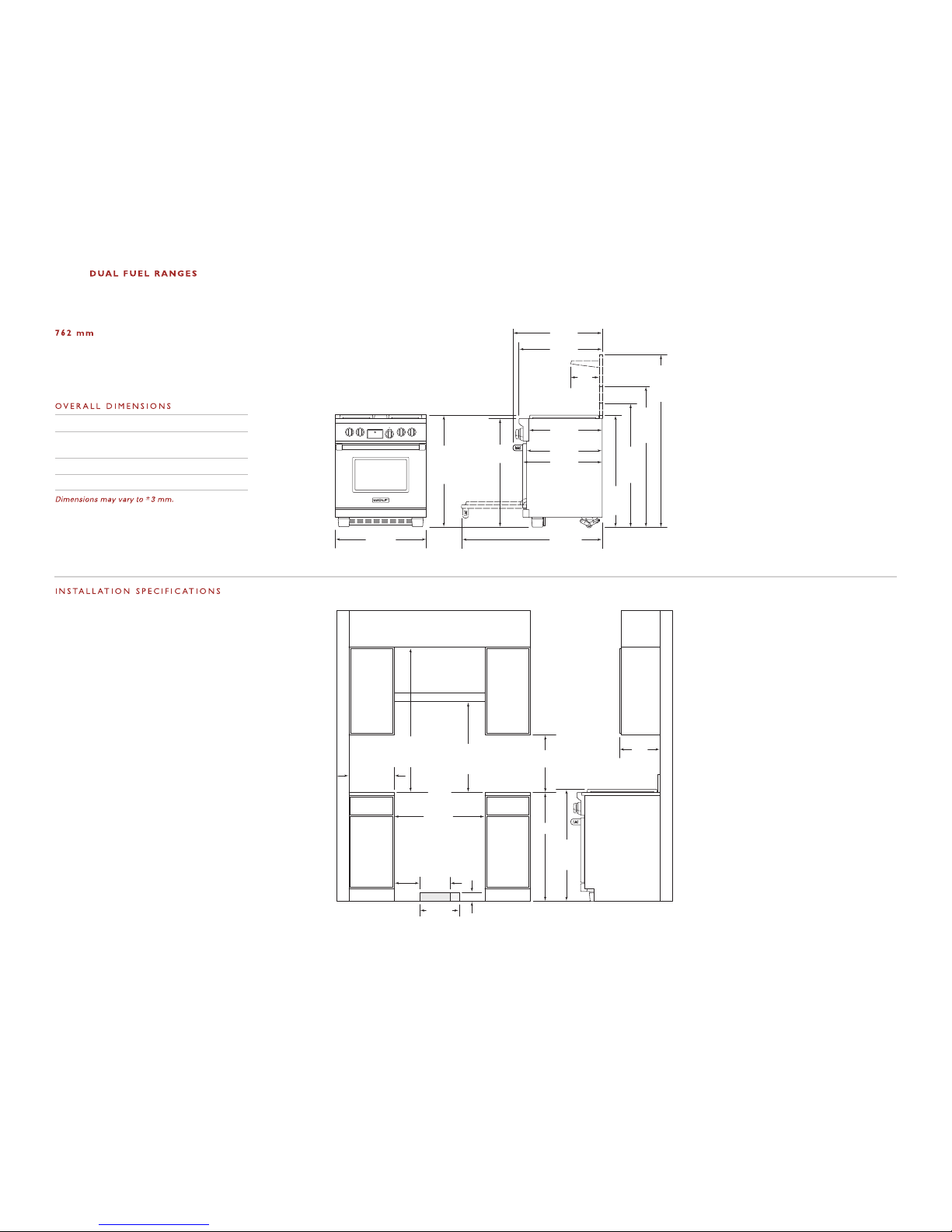
ICBDF304
OLF
330 mm
LOCATION OF
ELECTRICAL
914 mm
937 mm
TO
COOKING
SURFACE
600 mm min
COUNTERTOP TO
COMBUSTIBLE
MATERIALS
VENTILATION HOOD
457 mm min
TO COUNTERTOP
LOCATION OF GAS AND
ELECTRICAL EXTENDS 57 mm
ON FLOOR FROM BACK WALL
762 mm
FINISHED ROUGH
OPENING WIDTH
83 mm
216
mm
254 mm
LOCATION
OF GAS
SUPPLY
600 mm min TO
914 mm max
TO BOTTOM OF
VENTILATION HOOD
ISLAND INSTALLATIONS: 305 mm MINIMUM
CLEARANCE FROM BACK OF RANGE TO
COMBUSTIBLE REAR WALL ABOVE COUNTERTOP–
0 mm TO NON-COMBUSTIBLE MATERIALS
330 mm
max
152 mm
min TO
COMBUSTIBLE
MATERIALS
(BOTH SIDES)
759 mm
OVERALL WIDTH
937
mm
ISLAND
TRIM
1165
mm
WITH
254 mm
RISER
1419
mm
WITH
508 mm
RISER
1038
mm
WITH
127 mm
RISER
1194 mm
664 mm
635 mm
613 mm
699 mm
235
mm
749 mm
OVERALL DEPTH
*937 mm MIN TO 991 mm MAX.
911
mm
937 mm
OVERALL
HEIGHT TO
COOKING
SURFACE*
Overall Width 759 mm
Overall Height
(to cooking surface) 937 mm
Overall Depth 749 mm
Opening Width 762 mm
DUAL FUEL RANGE
IMPORTANT NOTE: In non-island applications,
a minimum 127 mm riser is required for model
ICBDF304.
Note A:
Side clearances. If the distance
measured from the periphery of the
nearest burner to any vertical surface
is less than 200 mm, the surface shall
be protected in accordance with
AS/NZ5601.
Note B:
The rangehood fitted above the
cooktop must be installed according
to the installation instructions for
the rangehood. A minimum
distance of 750 mm is required for a
range hood and 750 mm for an
exhaust fan
.
Page 5
5
I NS T A LL A TI O N I N S T R U C T I O N S
483 mm
LOCATIONOF
ELECTRICAL
914
mm
937 mm
TO
COOKING
SURFACE
VENTILATIONHOOD
457 mm min
TO COUNTERTOP
LOCATIONOF GAS AND
ELECTRICAL EXTENDS 76 mm
ON FLOOR FROM BACK WALL
914 mm
FINISHED ROUGH OPENING WIDTH
83 mm
216
mm
381 mm
LOCATION
OF GAS
SUPPLY
mm min TO
914 mm max
TO BOTTOMOF
VENTILATIONHOOD
600 mm min
COUNTERTOP
TO COMBUSTIBLE
MATERIALS
762 mm min
FOR CHARBROILER
ISLAND INSTALLATIONS: 305 mm MINIMUM
CLEARANCE FROM BACK OF RANGE TO
COMBUSTIBLE REAR WALL ABOVECOUNTERTOP–
330 mm
max
911 mm
OVERALLWIDTH
1194 mm
699 mm
235
mm
749 mm
OVERALL DEPTH
LEGS AND CASTERS ALLOW
54 mm HEIGHT ADJUSTMENT
911
mm
937 mm
OVERALL
HEIGHT TO
COOKING
SURFACE
616 mm
641 mm
1064
mm
WITH
127 mm
RISER
1191
mm
WITH
254 mm
RISER
1445
mm
WITH
254 mm
RISER
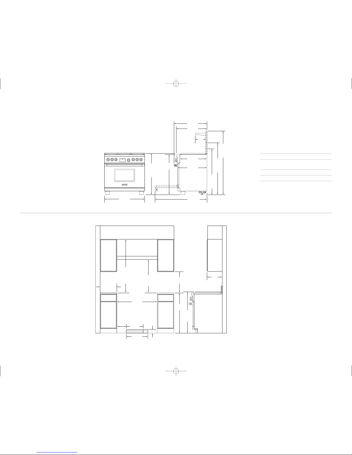
I N S T A L L A T I O N SPE C I F I C A T I O N S
O VERA L L D I M E N S I O N S
Overall Width 911 mm
Overall Height
(to cooking surface) 937 mm
Overall Depth 749 mm
Opening Width 914 mm
Dimensions may vary to±3 mm.
9 14 m m DU A L F U E L R A N G E S
M O D E L I C B D F 3 6 6
M O D E L I C B D F 3 6 4 C
M O D E L I C B D F 3 6 4 G
IMPORTANT NOTE: In non-island applications,
a mini mum 127 mm riser is required for model
ICBDF366 and minimum 254 mm ri ser required for
models ICBDF364C and ICBDF364G installed against
a combu stible surface. The island trim and 127 mm
riser may on ly be used against a non-combustible
surface for m odels ICBDF364C and ICBDF364 G .
NOTE
A
NOTE
B
Note A:
Side clearances. If the distance
measured from the periphery of the
nearest burner to any vertical surface
is less than 200 mm, the surface shall
be protected in accordance with
AS/NZ5601.
Note B:
The rangehood fitted above the
cooktop must be installed according
to the installation instructions for
the rangehood. A minimum
distance of 750 mm is required for a
range hood and 750 mm for an
exhaust fan
.
600
50 mm TO NON-COMBUSTIBLE MATERIALS
Page 6
6
W O L F DU A L F UE L R A N GE S
330 mm
LOCATIONOF
ELECTRICAL
914
mm
937 mm
TO
COOKING
SURFACE
VENTILATIONHOOD
LOCATIONOF GAS AND
ELECTRICAL EXTENDS 76 mm
ON FLOOR FROM BACK WALL
ISLAND INSTALLATIONS: 305 mm MINIMUM
CLEARANCE FROM BACK OF RANGE TO
COMBUSTIBLE REAR WALL ABOVECOUNTERTOP–
1219 mm
FINISHED ROUGH OPENING WIDTH
610 mm
83 mm
254 mm
LOCATION
OF GAS
SUPPLY
457 mm min
TO COUNTERTOP
mm min TO
914 mm max
TO BOTTOMOF
VENTILATIONHOOD
600 mm min
COUNTERTOP
TO COMBUSTIBLE
MATERIALS
762 mm min
FOR CHARBROILER
330 mm
max
1216 mm
OVERALLWIDTH
1194 mm
699 mm
235
mm
749 mm
OVERALL DEPTH
LEGS AND CASTERS ALLOW
54 mm HEIGHT ADJUSTMENT
911
mm
937 mm
OVERALL
HEIGHT TO
COOKING
SURFACE
616 mm
641 mm
1064
mm
WITH
127 mm
RISER
1191
mm
WITH
254 mm
RISER
1445
mm
WITH
254 mm
RISER
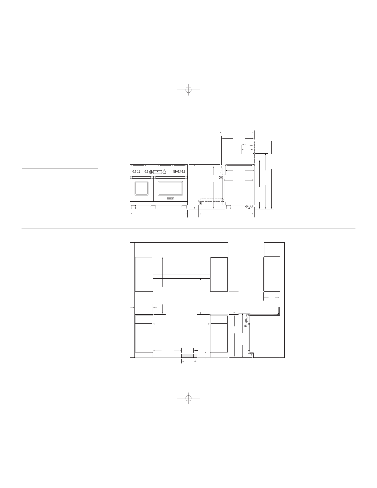
I N S T A L L A T I O N S P E C I F I C A T I O N S
O V E R A L L D I M E N S I O N S
Overall Width 1216 mm
Overall Height
(to cooking surface) 937 m m
Overall Depth 749 mm
Opening Width 1219 mm
Dimensions may vary to±3 mm.
1 21 9 m m D U A L F U E L R A N G E S
GC8 44FDBCI
I C B D F 4 8 4 F
C8 64FDBCI
I C B D F 4 8 6 G
IMPORTANT NOTE: In non-island applications, a
minimum 254 mm ris er is required for all 1219 mm
models installed against a combustible surface.
The is land trim and 127 mm riser may only be used
against a no n -combustible surf ace.
NOTE
B
Note A:
Side clearances. If the distance
measured from the periphery of the
nearest burner to any vertical surface
is less than 200 mm, the surface shall
be protected in accordance with
AS/NZ5601.
Note B:
The rangehood fitted above the
cooktop must be installed according
to the installation instructions for
the rangehood. A minimum
distance of 750 mm is required for a
range hood and
750 mm for an
exhaust fan
.
NOTE
A
600
50 mm TO NON-COMBUSTIBLE MATERIALS
Page 7

7
I NS T A LL A TI O N I N S T R U C T I O N S
330 mm
LOCATIONOF
ELECTRICAL
914
mm
937 mm
TO
COOKING
SURFACE
VENTILATIONHOOD
LOCATIONOF GAS AND
ELECTRICAL EXTENDS 76 mm
ON FLOOR FROM BACK WALL
83 mm
787 mm
254 mm
LOCATION
OF GAS
SUPPLY
1530 mm
FINISHED ROUGH OPENING WIDTH
457 mm min
TO COUNTERTOP
mm min TO
914 mm max
TO BOTTOMOF
VENTILATIONHOOD
600 mm min
COUNTERTOP
TO COMBUSTIBLE
MATERIALS
762mm min
FOR CHARBROILER
ISLAND INSTALLATIONS: 305 mm MINIMUM
CLEARANCE FROM BACK OF RANGE TO
COMBUSTIBLE REAR WALL ABOVECOUNTERTOP–
330 mm
max
1527 mm
OVERALLWIDTH
1064
mm
WITH
127 mm
RISER
1191
mm
WITH
254 mm
RISER
1445
mm
WITH
254 mm
RISER
1194 mm
616 mm
641 mm
699 mm
235
mm
749 mm
OVERALL DEPTH
LEGS AND CASTERS ALLOW
54 mm HEIGHT ADJUSTMENT
911
mm
937 mm
OVERALL
HEIGHT TO
COOKING
SURFACE
I N ST A L L AT I O N SPEC I F IC A T I O N S
O VERAL L D I M E N S I O N S
Overall Width 1527 mm
Overall Height
(to cooking surf ace) 937 mm
Overall Depth 749 mm
Opening Width 1530 mm
Dimensions may vary t o±3 mm.
1 52 4 m m DUA L F UE
I CBDF 6 0 6 C F
L R A N G E S
IMPORTANT NOTE: In non-island applications, a
minimum 254 mm ri s er is required for all 1524 mm
models installed against a combu s tible surface.
The is land trim and 127 mm riser may only be used
against a non- combustible surface.
NOTE
A
NOTE
B
Note A:
Side clearances. If the distance
measured from the periphery of the
nearest burner to any vertical surface
is less than 200 mm, the surface shall
be protected in accordance with
AS/NZ5601.
Note B:
The rangehood fitted above the
cooktop must be installed according
to the installation instructions for
the rangehood. A minimum
distance of 750 mm is required for a
range hood and 750 mm for an
exhaust fan
.
600
FC4 06FDBCI
50 mm TO NON-COMBUSTIBLE MATERIALS
Page 8

8
U NP A CK TH E R A N G E
Remove and discard a ll pack ing mat erials,
including cardboard a nd tape on the outside of
the range and inside the oven cavity.
Remove the box conta ining t he oven racks,
oven rack guides and broiler pan from in side
the oven cavity. Be sure to do this for both
oven cavities on the 1524 mm range.
Remove the burner gr ates an d styro foam of f
the top cooking surf ace. Be sure to remove the
burner caps packaged in styrofoam below t he
burner grates.
Do not discard the angle iron supplied w ith th e
range. This is the anti-tip bracket and must be
installed with the u nit. Re fer to anti-tip bracket
installation on page 11.
Carefully lift the r ange of f the pallet and
remove the styrofoam from the bottom of the
unit.
IMPORTANT NOTE:
Before moving the ra nge
into position, protec t any finished flooring with
appropriate materials to avoid damage to the
floor.
The rear of the rang e has rolling casters whic h
allows for easy move ment of the range by
picking up on the f ront of the unit. Refer to the
illustration below.
The dual fuel range comes from the facto ry at
an overall height of 911 mm from floor to the
top of the bullnose, before any height a djustment. The legs and c asters allow for 54 mm
height adjustment. Ref er to the illustration
below. Us e a 1 9 mm s ocket t o adjus t the rear
casters. Refer to th e insta llation specifications
illustration for your model on pages 4– 7 for
additional dimensions.
W O L F DU A L F UE L R A N GE S
Casters allow for 54 mm
height adjustment
Rolling casters.
Do not lift the r ange by the oven door
handle(s). Th is wil l dam age t he ov en do or
and hinges.
The dual fuel ra nge i s ver y hea vy. Use
caution when l ifting and moving th e uni t.
Secure oven do or(s) closed before
moving the uni t.
O VE N D O OR RE M O V A L
If removal of the ov en door (s) is necessary, a
hinge pin, supplied w ith th e range , will need to
be inserted in the appropriate hinge arm. For
each oven door, only one hinge arm is spring
loaded, requiring use of the hinge pin f or
removal of the oven door. The h inge pi n will
be found taped to t he insi de of the oven door.
For 762 mm and 914 mm ranges, the hinge pin
will be inserted thro ugh th e hole in the right
hinge arm (facing th e unit) . On 1 219 mm and
1524 mm ranges, the spring hinges are l ocated
on the outer edges of the unit. On thes e units ,
the left oven door will have the spring hinge
on the left side an d the right oven door will
have the spring hing e on t he righ t side. Refer
to the illustrations below for the locati on of the
spring hinge(s) for your model.
Place Hinge Pin on
Spring Hinge Side of Door
Place Hinge Pins on
Spring Hinge Side of Door
Spring hinge locati on for 762 mm
and 914 mm ranges.
Spring hinge locati ons for 12 19 mm
and 1524 mm ranges.
Failure to ins ert t he hi nge pi n in t he
appropriate h inge a rm wi ll ca use d amage
to the range. Mi nor i njuries may occur.
IMPORTANT NOTE:
The oven door(s) sho uld
not be removed unles s it i s neces sary to fit the
range through a tight doorway. Door remov al
should only be done by a qualified servi ce
technician or installe r. Door removal an d reinstallation may cause damage to the oven
porcelain interior.
Page 9

9
O VE N D O OR R E M O VA L
If removal of the oven door(s) is necessary,
follow thes e steps:
1)
Remove the low er kickplate assembly to
access the low er hinge retainer mount ing
screws.
2)
Open the oven door to its f ully opened
position and r emove both upper and lower
hinge retainer moun ting screws. The oven
gasket may hav e to be moved sl ightly to
access the bot tom screws.
3)
After removing the mounting screws, move
the hinge reta iner plate forward sli ghtly.
The hinge reta iner plate will re main on the
door hinge ass embly after the m ounting
screws have b een removed.
4)
Insert the sup plied door hinge p in through
the hole in t he app
ropriate hinge arm . Refer
to the illustr ation below.
5)
Carefully close the oven door to about a
60° angle from horizontal and lif t the door
away from the oven. A sligh t rocking
motion may be required for r emoval.
6)
For 1219 mm a nd 1524 mm ranges ,
complete these step s for both oven doors
IMPORTANT NOTE:
The dual fuel range must
be connected t o a regulated gas supply.
The rating pla te, located rear of r emovable
lower panel, h as information on the type of
gas that shoul d be used. If thi s information
does not agree with the type of gas avail able,
check with the local gas su pplier. A duplicate
pl
ate can be at tached to the insi de top of an
adjacent cupboard.
This appliance appl iance must be ins talled in a
position with the proper level o f ventilation. Do
not obstruct t he flow of combust ion and ventilation air.
The gas pressu re regulator supplied with the
appliance must be installed in l ine with the gas
pipe. (N.G. on ly).
If the applian ce cannot be adjus ted to perform
correctly contact Multyflex or t he local gas
utility. For service con tact telephone number
please refer p age 13.
For pressure t esting in excess of 3 .5 kPa (1/2”
psig) the appl iance and its indi vidual shut-off
va
lve must be d isconnected from the g as
supply piping syste m. For pressure t esting of
the gas piping system at pr essures equal to or
less than 3.5k Pa (1/2”psig) the appli ance must
be isolated fr om the gas supply system by
closing its in dividual shut off valv e during any
pressure testing.
The appliance shoul d not be connecte d to a
combustion product evacuation system.
Instruct the u ser in the operat ion of the appliance before le aving..
EXPLOSION HAZARD —
Securely tight en al l gas c onnections.
Failure to do so can result in ex plosion,
fire or death.
G AS S U P PL Y R E Q U I RE M E N TS G AS S U P PL Y C O N N E CT I O N
I NS T A L L AT I O N I N S T R U C T I O N S
Hinge
Retainer
Plate
Upper Mounting
Screw
Hinge
Pin
Kickplate
Oven door removal.
Do not lift or car ry th e ove n door by the
door handle.
Never test for a gas leak with a ma tch o r
other flame.
Gas connection:
The cooktop is adjusted to o perate on the gas
type specified on t he gas type label located on
the bottom of the unit. If in doubt as to the
type of gas a vailable contact the net work
operator or ga s supplier for co nfirmation of
gas type.
The cooktop mu st be
connected to t he gas
supply with up stream
connection of a n isolation valve in accordance
with the respe ctively
valid regulations. We
recommend that the
isolation valve be fitted
prior to the cooktop to
enable isolation of the cooktop f rom the gas
supply. The valve m ust be easily acce ssible at
all times.
Thi
s appliance ma y be connected with a hose
assembly, class B o r class D in accordance to
AS/NZS 1869. If connected with a hose assem bly ensure that th e gas
supply connection p oint is accessible
with the appli ance installed.
The position o f the inlet connect ion is
measured from botto m RH rear of unit ,
75 mm centre line from rear and 300 mm
centre line fr om RH side.
Fit regulator (N.G.) or Propane fi tting (Propane)
directly to th e R1/2” connection. dire ction for
gas flow is in dicated on the rea r of the regulator.
Check correct operat ion of each burner individually and in combination. Burner flames should
be clear blue, with no yello w tipping. If the
burners show a ny abnormality check tha t
burner heads ar e correctly located and refer to
the ‘trouble sh ooting’ guide on p age 26 & 27 o f
the Use and Ca re manual. If sati sfactory
performance can not be obtained, contac t
Multyflex or t he local gas utili ty. For service
contact number refer page 13 of t his booklet.
Note: These bur ner have no aerati on adjustme
nt.
It should be e xpressly noted that we cannot
accept any liab ility for direct or in direct damage
caused by wron g connection or im proper installation. When b eing repaired, the appl iance must
always be
disconnected
from the main
gas and electri city supply; if
required,notify
our customer
service.
Page 10

10
WOLF DU AL FUEL RA NG ES
IMPO RTANT NOTE
Be aware of local codes and ordinances
when installing your service.
ELECTRICAL REQUIREMENTS
GAS RATING
GAS RATIN G
Refer to page 13
REQUIRED POWER SUPPLY
Single phase: 220-240V AC; 50/60 Hz
3phase: 380-415V AC; 50/60 Hz
MAXIMUM CONNECTED LOAD
762 mm and 914 mm Dual Fuel ranges:
Single phase: 19 amps
3phase: 18 amps
1219 mm Dual Fuel ranges:
Single phase: 35 amps
3phase: 18 amps
1524 mm Dual Fuel ranges:
Single phase: 38 amps
3phase: 18 amps
Refer to the wiring diagram showing the connections
for each lead to the terminal box on the unit.
The complete appliance must be properly
grounded at all times when electrical power is
applied.
NOTE: Improper connection can result in a
re
hazard.
Before obtaining access to terminals, all supply
circuits must be disconnected.
Verify that power is disconnected from the
electrical box before proceeding.
Open the terminal box to expose the screws with
corresponding numbers. Run the cord through the
strain relief hole and into the terminal box.
For Single Phase Install (Line, Neutral, Ground):
Loosen the 1, 5, and ground screws. Attach the
Neutral wire to the number 5 position. Line should be
attached to the 1 postion and attach the ground to
the corresponding ground screw.
For 3phase Install (L1, L2, L3, Neutral, Ground):
Loosen the 1, 2, 3 and remove the copper bars.
Loosen 5 and ground screws. Attach L1 to position
1. L2 to position 2. L3 to position 3. Neutral wire to
position 5 and attach the ground to the corresponding ground screw.
IMPORTANT NOTE:
Connection of this appliance
should be through a fused connection unit or a
suitable isolator, which complies with national and
local safety regulations. The o
switch should
be easily accessible after the appliance has been
installed. If the switch is not accessible after installation (depending on country) an additional means of
disconnection must be provided for all poles of the
power supply. When switched
there must be an
all pole contact gap of 3 mm in the isolator switch.
This 3 mm contact disconnect gap must apply to
any isolator switch, fuses and/or relays according to
EN60335.
Copper bars must be removed from positions 1,
2, and 3 when connecting to 3phase power.
Single phase wiring diagram
3phase wiring diagram
Page 11

DRYWALL APPLICATIONS
After properly positioning the anti-tip bracket, use wall
anchors to fasten it to the wall. Using a Philips screwdriver
or a low rpm screw gun, drive the anchor into the surface
of the wallboard until the two cutting blades penetrate the
surface. Use gentle forward pressure to rotate the collar until
flush with the surface of the wall. Refer to the illustrations
below. Use #8 screws and flat washers to fasten the anti-tip
bracket to the wall.
IMPORTANT NOTE:
Pre-drill holes if difficulty is encountered during installation of the wall anchor. For hard wallboard or double-board construction, use a 6 mm drill bit. For
solid plaster, use a 11 mm drill bit.
WOOD FLOOR APPLICATIONS
After properly positioning the anti-tip bracket, drill 5 mm pilot
holes through the floor. Use #12 screws and flat washers to
secure the bracket to the floor.
C ONCRETE FLOOR APPLICATIONS
After properly positioning the anti-tip bracket drill 10 mm
holes into the concrete a minimum of 38 mm deep. Use 10
mm wedge anchors to secure the bracket to the floor.
ANTI-TIP BOLT ADJUSTMENT
Once the bracket is secured in place, adjust the
anti-tip bolt
at the back of the range so the top of the washer is 22 mm
maximum from the floor. Slide the range into the opening and
verify the anti-tip bolt is engaged. Refer to the illustrations
below.
IMPORTANT NOTE:
The top of the range must be level.
Use the adjustable front legs and the rear casters to level
the range.
Raise the unit to its desired height by adjusting the front
legs and rear casters. The legs and casters allow for 54 mm
height adjustment. Use a 19 mm socket to adjust the rear
casters. The front legs are adjusted by rotating the bottom
hexagonal portion of the leg.
The anti-tip bracket can be installed by securing it to the wall
or floor using the supplied hardware.
Refer to the chart and illustration below to determine the
proper distance from the left side of the opening to the
anti-tip bracket. This will ensure the anti-tip bolt properly
engages the bracket.
MODEL A
762 mm Range 5 mm
914 mm Range 14 mm
1219 mm Range 5 mm
1524 mm Range 8 mm
ANTI- TIP BRACKET INS TALLATI ON
O VEN DOOR REINSTALLATION
IMPORTANT NOTE:
The oven door(s) should not be removed
unless it is necessary to fit the range through a tight
doorway. Door removal should only be done by a qualified
service technician or installer. Door removal and reinstallation may cause damage to the oven porcelain interior.
A
ANTI-TIP
BRACKET
Anti-tip bracket location.
ANTI-TIP
BRACKET
WALL
ANCHOR
Wall anchor installation.
22 mm MAX
ANTI-TIP
BOLT
Anti-tip bolt adjustment.
ANTI-TIP
DEVICE
ENGAGED
Anti-tip bolt engaged.
Hinge
Retainer
Plate
Upper Mounting
Screw
Hinge
Pin
Kickplate
Oven door reinstallation.
If oven door(s) have been removed, follow these steps to
reinstall:
1)
Hold the oven door on both sides and position it with
door hinges aligned with openings in the oven frame.
2)
Holding the oven door at an approximate 30° angle from
vertical, slide the hinges into the openings until the
bottom hinge arms drop fully into the hinge receptacles.
3)
Open the oven door to its fully opened position. Remove
the hinge pin from the appropriate hinge arm. Refer to
the
illustration below.
4)
Reinstall the hinge retainer plate with upper and lower
mounting screws.
5)
Open and close the door completely to ensure that it is
properly installed.
6)
For 1219 mm and 1524 mm ranges, complete these steps
for both oven doors.
7)
Reinstall the lower kickplate assembly.
IMPORTANT NOTE:
Fully extend the hinge claw which is
opposite the hinge pin location and insert into the hinge
pocket prior to inserting opposite side. This will ease the
installation of the oven door.
This range can tip. Injury to persons could result.
Install the anti-tip bracket supplied with the range.
Do not lift or carry the oven door by the door handle.
INSTALLATION INS TRUCTIONS
Page 12

12
W O L F DU A L F UE L R A N GE S
R EM O V I NG T H E R A N G E
If removing the dual fuel range is neces sary fo r
cleaning or service, shut off the gas su pply.
Disconnect the gas s upply an d elec trical
connections to the u nit, th en remo ve the
range. Reinstall in the reverse order and be
sure to check the g as conn ection for leaks.
Refer the Wolf dual fuel ranges use & care
information included w ith the range for
cleaning recommendatio ns.
T RO U B L ES H O O T I N G
IMPORTANT NOTE:
If the dual fuel ran ge
does not operate prop erly, follow the se
troubleshooting steps:
Verify that power is being supp lied to the
range.
Check the gas supply and electrical
connections to ensure that the installatio n
has been completed c orrectly.
Check that gas valve s are turned to the ON
position.
Follow troubleshooting procedures as
described in the Wolf dual fuel ranges
use & care informati on.
If the range still does not work, contac t a
Wolf dealer. Do n ot atte mpt to repair the
range yourself. Wolf
is not responsible fo r serv ice req uired t o
correct a faulty ins tallation.
Be sure to disco nnect the gas suppl y and
electrical co nnections before re moving
the range.
V ER I F Y R A N G E O P E R A T I O N
IMPORTANT NOTE:
Prior to operating
the range, be sure to read the entire
Wolf dual fuel ranges use & care information included with the range for
important safety and service information.
Install the oven rac k guide s onto the
shoulder screws locat ed on the interior
side walls of the o ven. Sl ide the oven
racks onto the suppor t rack s withi n the
oven. There are thre e racks per oven,
except for the 457 m m oven which has
two racks. Place the broiler pan and gri d
on a rack within th e oven, if desired.
Turn on the p ower su pply to the range.
The control panel sh ould be closed (no
visible control pads) . Touch and slightly
depress the flame gra phic o n the hidden
control panel to ope n.
Set the time of day by pressing the
touch pad, scroll to the desired time by
using the or arrows, then touch
. After setting the time, the hidden
control panel can be closed. The control
panel does not have to be open to
operate the oven.
Select any of the ei ght co oking m odes
by using the oven c ontrol knob bezel
and turning to the d esired mode. Once
the mode has been s elected, the temperature can be adjuste d by t urning the
temperature readout k nob clo ckwise to
increase the temperat ure or counterclockwise to decrease the temperature.
Verify that the oven is coming up to
temperature. For a 1 219 mm or 1524 mm
range, follow this p rocedure for the both
ovens.
IMPORTANT NOTE:
A small amount of
smoke and odor may be noticed during
the initial break-in period. Refer to the
use & care informati on for additional
information.
C OO K T O P O P E R A T I O N
The cooktop burner use s an e lectronic igniter in
place of a standing p ilot. W hen the cooktop control
knob is pushed in and turned to the position,
the system creates a spark to light the bu rner. This
sparking continues for 4 seconds or until the electronic ignition senses a flame, which ever comes
first. If the igniter fails to ignite the gas in 4 seconds,
the gas safety shutoff valve will close, e liminating
the gas flow for 5 s econds. The valve will reopen
after the purge time of 5 seconds, and the igniter
will automatically atte mpt to re-ignite the gas. T his
cycle of events is at tempted 3 times. After the th ird
attempt, in order for gas to flow to the burner once
again, the user must return the knob to th e
position and then turn the knob to the
position.
To check operatio n of th e cookt op burn er, push in
and turn the control knob to the position. The
flame should light wit hin fou r secon ds.
If the burner does no t light properly, turn the c ontrol
knob to the position. Check that the burner
head is in the proper position. Check that the power
supply cord is plugged in and that the cir cuit br eaker
or house fuse has not blown.
Check operation again; If flame is not est ablished
within the ignition cy cle tim e, rele ase the knob, open
a door and wait 1 mi nute bef ore att empting a new
ignition procedure.
If the flames are ext inguished - for any reason
whatever - turn OFF t he cont rol kno b and w ait at
least 1 minute before retrying to ignite t he burne r.
Ensure that the flames do not extinguish w hen you
reduce to low flame q uickly. Check co rrect op eration
of each burner indivi dually and in combination.
F LA M E H E IG H T A ND AP P EA R A N CE
The flame on natural gas should be blue wi th a
deeper blue core. and no yellow tipping. I f burner s
show any abnormality check that burner head s are
correctly located and refer to the ‘ troubl e shoot ing
guide’ on this page. If satifactory perform ance can
not be obtained, cont act Mult yflex. For service
contact number refer page 13 of this bookle t.
IMPORTANT NOTE:
Initial lighting of the surface
burners may take sli ghtly l onger, as air in t he
system must be purge d befor e gas can be supplied
to the burner.
Page 13

13
W IR I N G D I A G R A M
The wiring dia gram covering the con trol circuit
is located rea r of the removabl e lower panel.
The information and im ages in th i s book are th e
copyright proper ty of Wolf App liance, Inc., an
affiliate of Sub-Ze ro, Inc . Neith e r this boo k nor any
information or imag es cont ained he rein ma y be
copied or used in whole or in part w i thout t he
express wri tte n pe rmission of Wolf Appliance, Inc .,
an affiliate of Sub-Ze ro, Inc .
©Wolf Applian ce, Inc . all righ ts reser ve
d.
I NS T A LL A T I O N I N S T R U C T I O N S
S ER V I C E I N FO R M AT I O N
When requesting in formation, literature,
replacement parts or service, al ways refer to
the model and serial number of your dual fue l
range. This in formation is found on the
product rating plat e located rear of the removable lower pan el. Refer to the illustration below.
Record the rat ing plate information
below for futu re reference.
Model Number
Serial Number
Installation Date
Wolf Dealer and Phon e
B E FO R E C A L L IN G F O R SE R V I C E
Before calling y
our Wolf dealer, refer t o the
troubleshooting guid e on page 12. Che ck
the household fuse or circuit b reaker to see if it
has been blown or tripped a nd that the elect rical connection to the appliance has not been
disconnected. A po wer outage may als o have
caused a disru ption in service.
For service c all:
1300 808 859
C O N T A C T
I N F O R M AT I O N
Website:
www.multyflex.com. au
I M P O RT E D &
D I ST R I B U T E D B Y :
MultyFlex
Made in USA
GSCS20230
SAI GLOBAL
AS4551
Electrical compliance: in ac cordance with
AS/NZS3100 240 V AC, 4.5 kW/19 Amps, 50 Hz
Imported &
distributed
by
Suite 1, 151 Barkley Avenue. Burnley VIC 3121
t: +61 3 9421 0232
Model
No:
ICBDF304
Serial No:
Gas
type
NG LPG
Test point p ress. (kPa) 1.0 2.75
Injector sizes (mm)
RHF
RHR
LHF
LHR
1.80
1.80
1.80
1.35
1.09
1.09
1.09
0.89
Total Consumption (MJ/h) 51.0 51.1
MF027
Made in USA
GSCS20230
SAI GLOBAL
AS4551
Electrical compliance: in a ccordance with
AS/NZS3100 240 V AC, 4.5 kW/19 Amps, 50 Hz
Imported &
distributed
by
Suite 1, 151 Barkley Avenue. Burnley VIC 3121
t: +61 3 9421 0232
Model
No:
ICBDF366
Serial No:
Gas
type
NG LPG
Test point press. (kPa) 1.0 2.75
Injector sizes (mm)
RHF/CF
RHR/CR
LHF
LHR
1.80
1.80
1.80
1.35
1.09
1.09
1.09
0.89
Total Consumption (MJ/h ) 79.0 79.1
MF022
Made in USA
GSCS20230
SAI GLOBAL
AS4551
Electrical compliance: in a ccordance with
AS/NZS3100 240 V AC, 4.5 kW/19 Amps, 50 Hz
Imported &
distributed
by
Suite 1, 151 Barkley Avenue. Burnley VIC 3121
t: +61 3 9421 0232
Model
No:
ICBDF364C
Serial No:
Gas
type
NG
LPG
Test point press. (kPa) 1.0 2.75
Injector sizes (mm)
RHF
RHR
Grill
LHF
LHR
1.80
1.80
1.78
1.80
1.35
1.09
1.09
1.09
1.09
0.89
Total Consumption (MJ/h ) 66.0 66.1
MF028
Made in USA
GSCS20230
SAI GLOBAL
AS4551
Electrical compliance: in a ccordance with
AS/NZS3100 240 V AC, 4.5 kW/19 amps, 50 Hz
Imported &
distributed
by
Suite 1, 151 Barkley Avenue. Burnley VIC 3121
t: +61 3 9421 0232
Model
No:
ICBDF364G
Serial No:
Gas
type
NG LPG
Test point press. (kPa) 1.0 2.75
Injector sizes (mm)
RHF
RHR
Griddle
LHF
LHR
1.80
1.80
1.70
1.80
1.35
1.09
1.09
1.09
1.09
0.89
Total Consumption (MJ/h ) 66.0 66.1
MF018
Made in USA
GSCS20230
SAI GLOBAL
AS4551
Electrical compliance: in acc ordance with
AS/NZS3100 240 V AC, 8.4 kW/35 Amps, 50 Hz
Imported &
distributed
by
Suite 1, 151 Barkley Avenue. Burnley VIC 3121
t: +61 3 9421 0232
Model
No:
ICBDF484CG
Serial No:
Gas
type
NG
LPG
Test point press. (kPa) 1.0 2.75
Injector sizes (mm)
RHF
RHR
Grill
Griddle
LHF
LHR
1.80
1.80
1.78
1.70
1.80
1.35
1.09
1.09
1.09
1.09
1.09
0.89
Total Consumption (MJ/h) 81.0 81.1
MF016
Made in USA
GSCS20230
SAI GLOBAL
AS4551
Electrical compliance: in ac cordance with
AS/NZS3100 240 V AC, 8.4 kW/35 Amps, 50 Hz
Imported &
distributed
by
Suite 1, 151 Barkley Avenue. Burnley VIC 3121
t: +61 3 9421 0232
Model
No:
ICBDF484F
Serial No:
Gas
type
NG
LPG
Test point press. (kPa) 1.0 2.75
Injector sizes (mm)
RHF
RHR
French top
LHF
LHR
1.80
1.80
1.80
1.80
1.35
1.09
1.09
1.09
1.09
0.89
Total Consumption (MJ/h) 65.0 65.1
MF017
Made in USA
GSCS20230
SAI GLOBAL
AS4551
Electrical compliance: in ac cordance with
AS/NZS3100 240 V AC, 8.4 kW/35 Amps, 50 Hz
Imported &
distributed
by
Suite 1, 151 Barkley Avenue. Burnley VIC 3121
t: +61 3 9421 0232
Model
No:
ICBDF486C
Serial No:
Gas
type
NG LPG
Test point press. (kPa) 1.0 2.75
Injector sizes (mm)
RHF
RHR
Grill
LHF/CF/CR
LHR
1.80
1.80
1.78
1.80
1.35
1.09
1.09
1.09
1.09
0.89
Total Consumption (MJ/h) 94.0 94.1
MF029
Made in USA
GSCS20230
SAI GLOBAL
AS4551
Electrical compliance: in ac cordance with
AS/NZS3100 240 V AC, 8.4 kW/35 Amps, 50 Hz
Imported &
distributed
by
Suite 1, 151 Barkley Avenue. Burnley VIC 3121
t: +61 3 9421 0232
Model
No:
ICBDF486G
Serial No:
Gas
type
NG LPG
Test point press. (kPa) 1.0 2.75
Injector sizes (mm)
RHF/CF
RHR/CR
Griddle
LHF
LHR
1.80
1.80
1.70
1.80
1.35
1.09
1.09
1.09
1.09
0.89
Total Consumption (MJ/h) 94.0 94.1
MF030
Made in USA
GSCS20230
SAI GLOBAL
AS4551
Electrical compliance: in acc ordance with
AS/NZS3100 240 V AC, 9.1 kW/ 38 Amps, 50 Hz
Imported &
distributed
by
Suite 1, 151 Barkley Avenue. Burnley VIC 3121
t: +61 3 9421 0232
Model
No:
ICBDF604CF
Serial No:
Gas
type
NG
LPG
Test point p ress. (kPa) 1.0 2.75
Injector sizes (mm)
RHF
RHR
Grill
French top
LHF
LHR
1.80
1.80
1.78
1.80
1.80
1.35
1.09
1.09
1.09
1.09
1.09
0.89
Total Consumption (MJ/h) 80.0 81.1
MF026
Made in USA
GSCS20230
SAI GLOBAL
AS4551
Electrical compliance: in acc ordance with
AS/NZS3100 240 V AC, 9.1 kW/38 amps, 50 Hz
Imported &
distributed
by
Suite 1, 151 Barkley Avenue. Burnley VIC 3121
t: +61 3 9421 0232
Model
No:
ICBDF606CG
Serial No:
Gas
type
NG LPG
Test point p ress. (kPa) 1.0 2.75
Injector sizes (mm)
RHF/CF
RHR/CR
Grill
Griddle
LHF
LHR
1.80
1.80
1.78
1.70
1.80
1.35
1.09
1.09
1.09
1.09
1.09
0.89
Total Consumption (MJ/h) 109.0 109.1
MF023
Page 14

14
W i r i n g d i a g r a m
Page 15

15
W i r i n g d i a g r a m
Page 16

16
W i r i n g d i a g r a m
Page 17

17
W i r i n g d i a g r a m
Page 18

Page 19

Page 20

Imported&distribute d by Multyfle x
www.multyfl ex.com.au
MF038
 Loading...