

Page 1
Design Guide
REVISED 2/2020
Page 2

Design Guide
2 | Wolf Customer Care 800.222.7820
Features and specifications are subject to change at any
time without notice. Visit wolfappliance.com/specs for the
most up-to-date information.
Throughout this guide, dimensions may vary by ± ⁄"
Dimensions in parentheses are millimeters unless otherwise
specified.
(3).
Page 3

Contents
Contents
4 M Series Ovens
16 E Series Ovens
30 L Series Oven
34 Convection Steam Ovens
40 Speed Ovens
46 Microwave Ovens
60 Warming Drawers
66 Induction/Electric Cooktops
74 Gas Cooktops
80 Module Cooktops
90 Coee Systems
96 Cup Warming Drawers
100 Vacuum Seal Drawer
104 Dual Fuel Ranges
108 Gas Ranges
112 Induction Ranges
116 Sealed Burner Rangetops
120 Outdoor Grills/Modules
132 Cooktop Ventilation Hoods
144 Downdraft Ventilation
150 Pro Ventilation Hoods
160 Wolf Warranty
wolfappliance.com | 3
Page 4
M Series Ovens
UPPER OVEN LOWER OVEN
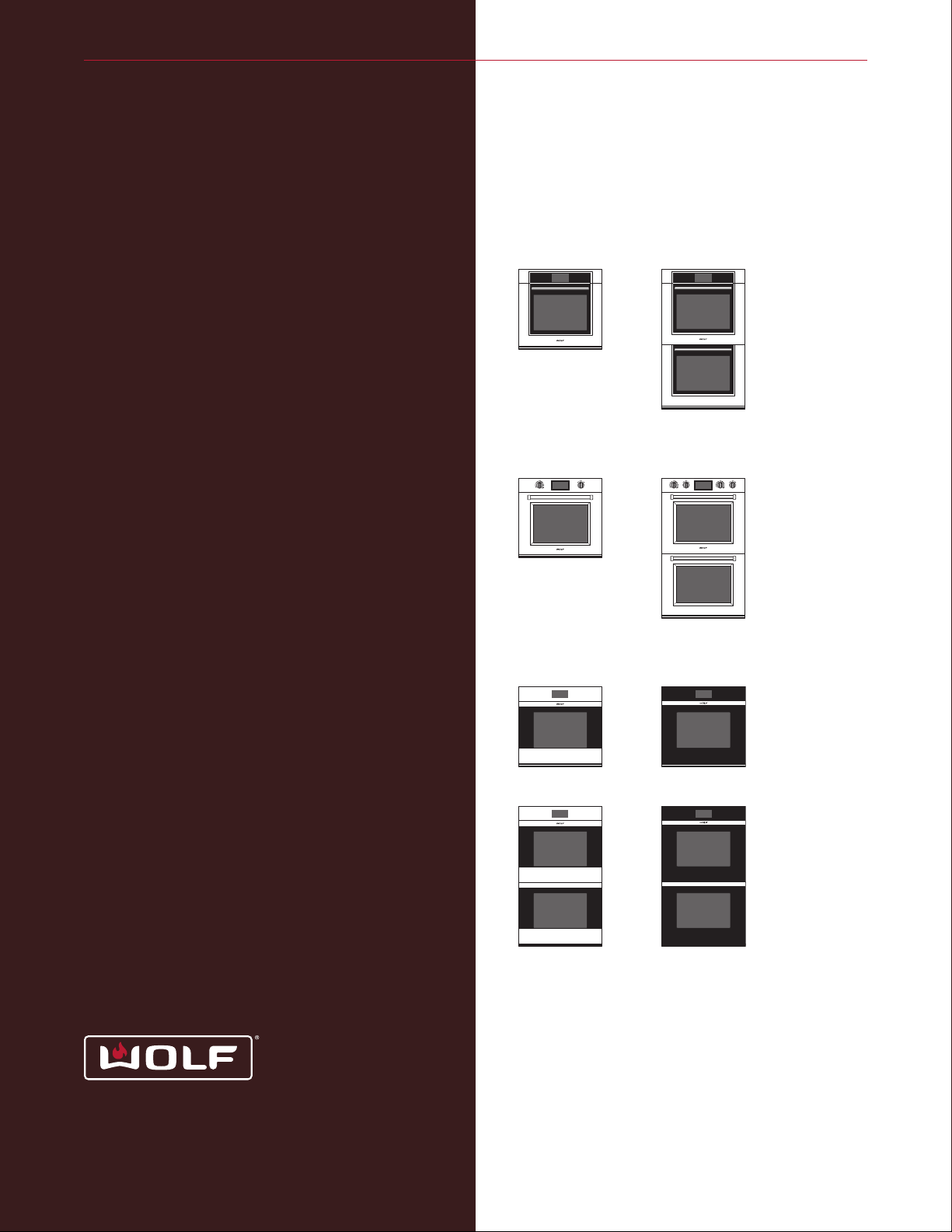
M Series Built-In Ovens
Contemporary M series ovens include stainless
steel and black glass models. Superior performance features include a more advanced dual
vertical convection fan system, touchscreen
controls, convenient preset cooking programs,
and improved interior lighting. There is more
usable space inside for deliciousness on a grand
scale. M series ovens can be installed in a standard or flush inset application.
M SERIES OVENS
TRANSITIONAL
SO30TM/S/TH
DO30TM/S/TH
PROFESSIONAL
SO30PM/S/PH
DO30PM/S/PH
CONTEMPORARY
4 | Wolf Customer Care 800.222.7820
SO30CM/S
DO30CM/S
SO30CM/B
DO30CM/B
Page 5
M Series Ovens
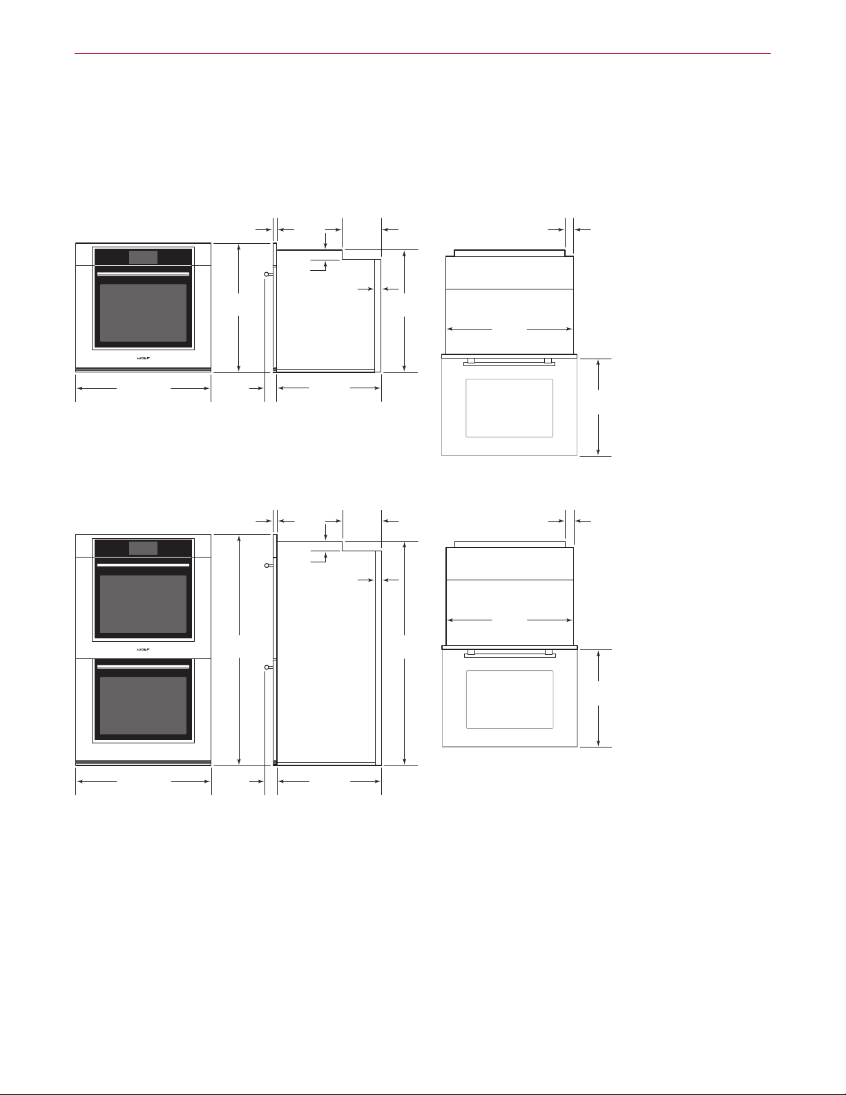
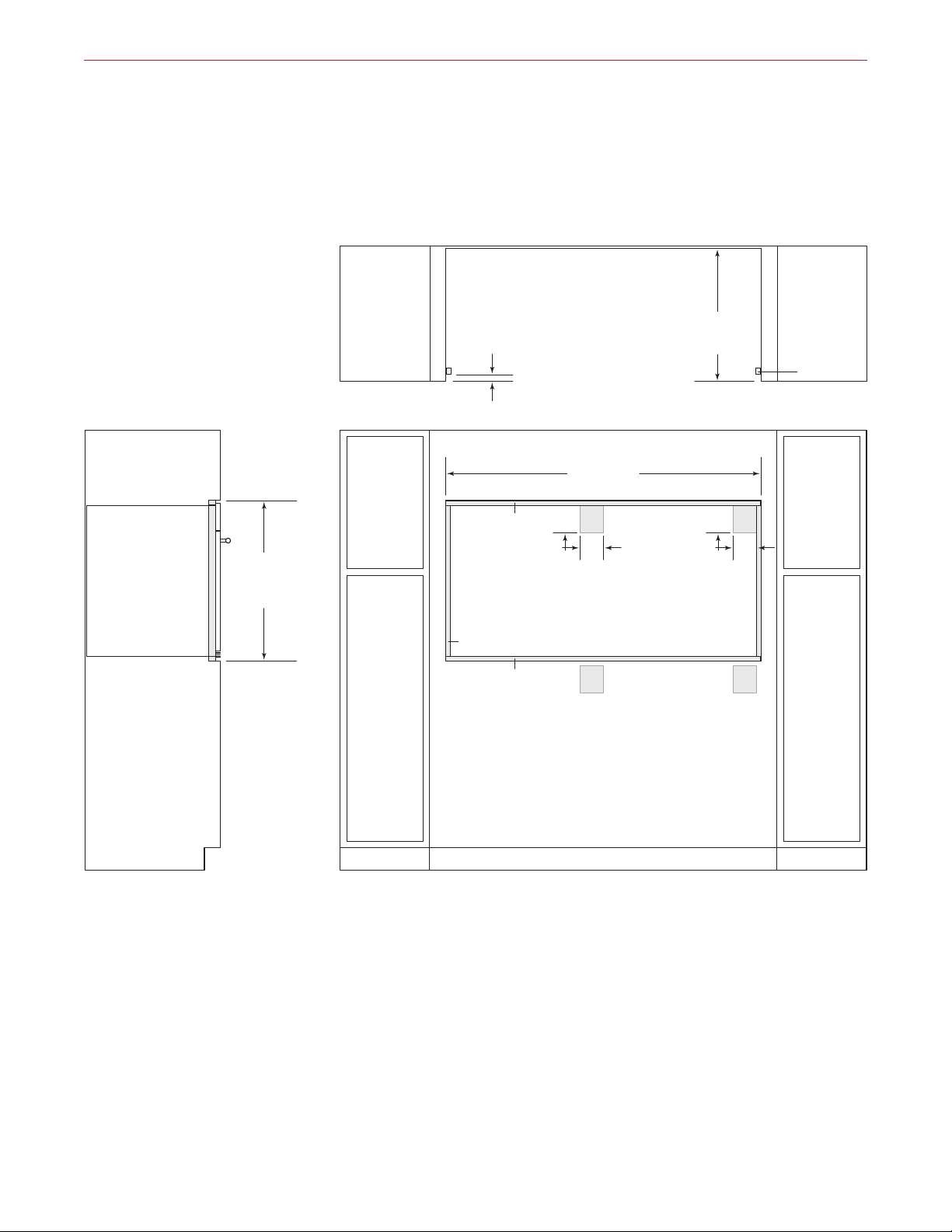
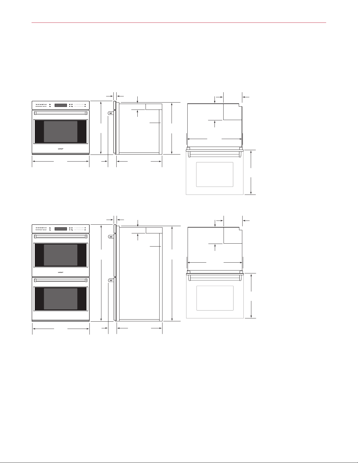
30" M Series Built-In Ovens
TRANSITIONAL SINGLE OVEN
281/2"
(723)
297/8" (759)
21/2"
(65)
TRANSITIONAL DOUBLE OVEN
507/8"
(1291)
7
/8"
(22)
2" (51)
13/8"
CONDUIT
CHANNEL
23" (584)
BEHIND FRAME
7
/8"
(22)
2" (51)
13/8"
CONDUIT
CHANNEL
(36)
(36)
85/8"
(218)
85/8"
(218)
27"
(686)
493/8"
(1254)
17/8"
(46)
281/2"
(724)
OPEN OVEN DOOR
17/8"
(46)
281/2"
(724)
213/8"
(543)
297/8" (759)
21/2"
(65)
23" (584)
BEHIND FRAME
OPEN OVEN DOOR
213/8"
(543)
wolfappliance.com | 5
Page 6

M Series Ovens
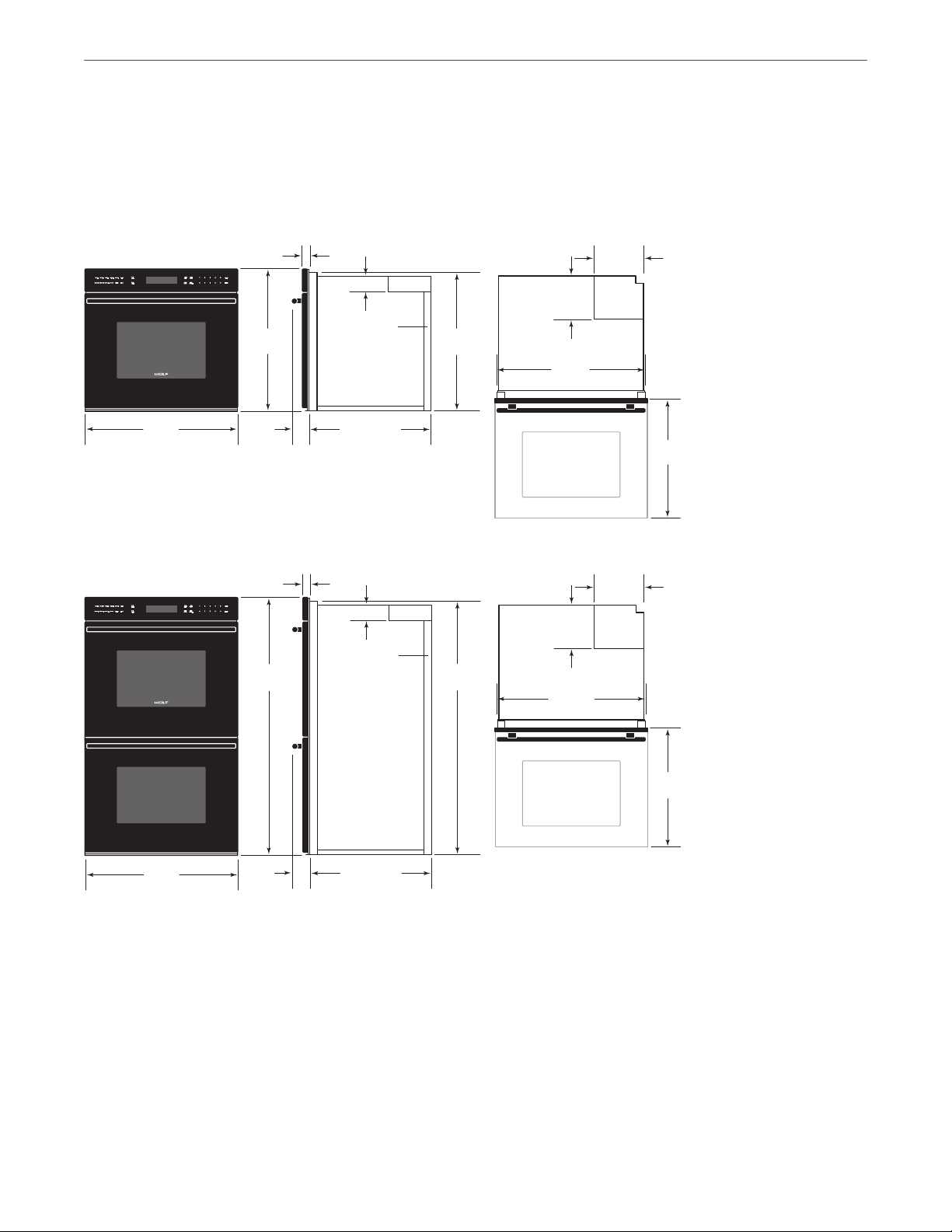
30" M Series Built-In Ovens
PROFESSIONAL SINGLE OVEN
281/2"
(723)
297/8" (759)
31/4"
(83)
PROFESSIONAL DOUBLE OVEN
UPPER OVEN LOWER OVEN
507/8"
(1291)
7
/8"
(22)
2" (51)
13/8"
CONDUIT
CHANNEL
23" (584)
BEHIND FRAME
7
/8"
(22)
2" (51)
13/8"
CONDUIT
CHANNEL
(36)
(36)
85/8"
(218)
85/8"
(218)
27"
(686)
493/8"
(1254)
17/8"
(46)
281/2"
(724)
OPEN OVEN DOOR
17/8"
(46)
281/2"
(724)
213/8"
(543)
297/8" (759)
31/4"
(83)
6 | Wolf Customer Care 800.222.7820
23" (584)
BEHIND FRAME
OPEN OVEN DOOR
213/8"
(543)
Page 7
M Series Ovens
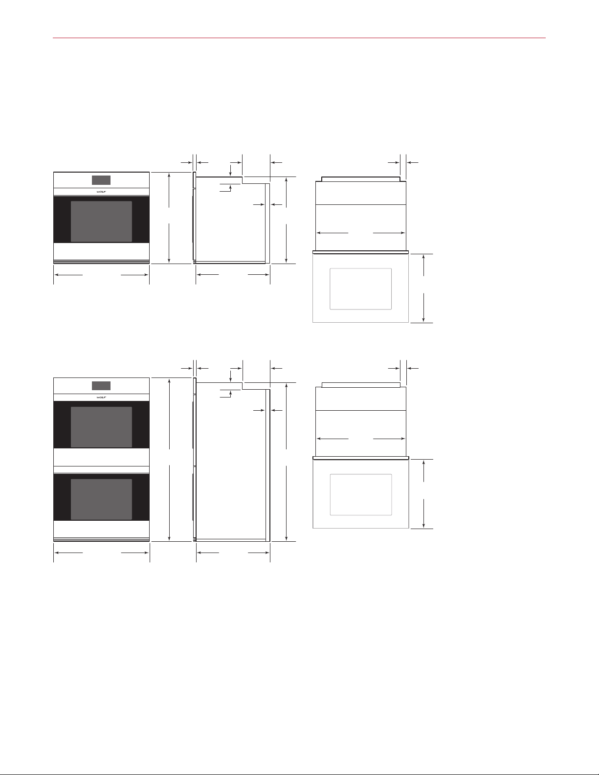
30" M Series Built-In Ovens
CONTEMPORARY STAINLESS STEEL SINGLE OVEN
7
(22)
/8"
85/8"
(218)
2" (51)
(36)
13/8"
CONDUIT
CHANNEL
23" (584)
BEHIND FRAME
297/8" (759)
281/2"
(723)
CONTEMPORARY STAINLESS STEEL DOUBLE OVEN
507/8"
(1291)
7
(22)
2" (51)
/8"
(36)
13/8"
CONDUIT
CHANNEL
85/8"
(218)
27"
(686)
493/8"
(1254)
17/8"
(46)
281/2"
(724)
OPEN OVEN DOOR
17/8"
(46)
281/2"
(724)
213/8"
(543)
297/8" (759)
23" (584)
BEHIND FRAME
OPEN OVEN DOOR
213/8"
(543)
wolfappliance.com | 7
Page 8

M Series Ovens
30" M Series Built-In Ovens
CONTEMPORARY BLACK GLASS SINGLE OVEN
1"
(25)
2" (51)
(36)
13/8"
CONDUIT
CHANNEL
23" (584)
BEHIND FRAME
297/8" (759)
281/2"
(723)
CONTEMPORARY BLACK GLASS DOUBLE OVEN
1"
(25)
2" (51)
(36)
13/8"
CONDUIT
CHANNEL
507/8"
(1291)
85/8"
(218)
85/8"
(218)
27"
(686)
493/8"
(1254)
17/8"
(46)
281/2"
(724)
OPEN OVEN DOOR
17/8"
(46)
281/2"
(724)
213/8"
(543)
297/8" (759)
8 | Wolf Customer Care 800.222.7820
23" (584)
BEHIND FRAME
OPEN OVEN DOOR
213/8"
(543)
Page 9

M Series Ovens
Planning Information
The M series oven can be installed in a standard or flush
inset application. If a cooktop is being installed above an
oven, a minimum of ⁄"
(6) is required between the units.
The location of the electrical supply within the oven opening may require additional cabinet depth.
Finish the edges of the opening. They may be visible when
the door is open.
For standard installations, the face trim will overlap stiles
and rails. Refer to the chart below.
For flush inset installations, a minimum ⁄"
(3) reveal is
required on all sides. To ensure consistent reveals, each
corner of the opening must be exactly 90°.
INSTALLATION REQUIREMENTS
BASE SUPPORT MIN
Single Oven 250 lb (115 kg)
Double Oven 400 lb (181 kg)
TRIM OVERLAP
Top 1" (25)
Bottom 0" (0)
Sides ⁄" (18)
ELECTRICAL REQUIREMENTS
Installation must comply with all applicable electrical codes.
Locate the electrical supply flush with the back wall and
within the shaded area shown in the illustrations on the
following pages. For ease of installation, the electrical
supply for the oven can be placed in an adjacent cabinet
within reach of the conduit.
Performance may be compromised if the electrical supply
is less than 240 volts.
The oven is supplied with a conduit consisting of two
insulated hot lead conductors and a bare ground conductor. The wiring diagram covering the control circuit is
provided with the oven.
ELECTRICAL REQUIREMENTS—SINGLE OVEN
Electrical Supply grounded, 240/208 VAC, 60 Hz
Service 30 amp dedicated circuit
Conduit 4' (1.2 m)
Total Amps 22
Max Connected Load 5.4 kW
DUAL INSTALLATION
Two 30" single M series ovens can be installed side by
side in a standard or flush inset application. A dual installation kit is required. To maintain appropriate airflow, the
ovens must be installed into one opening. Any cosmetic or
structural material placed between the ovens will impede
airflow and is not recommended. Refer to the illustrations
on pages 14–15.
The dual installation kit is available through an authorized
Wolf dealer. For local dealer information, visit the find a
showroom section of our website, wolfappliance.com.
ELECTRICAL REQUIREMENTS —DOUBLE OVEN
Electrical Supply grounded, 240/208 VAC, 60 Hz
Service 50 amp dedicated circuit
Conduit 5'
Total Amps 45
Max Connected Load 10.8 kW
(1.5 m)
wolfappliance.com | 9
Page 10
SIDE
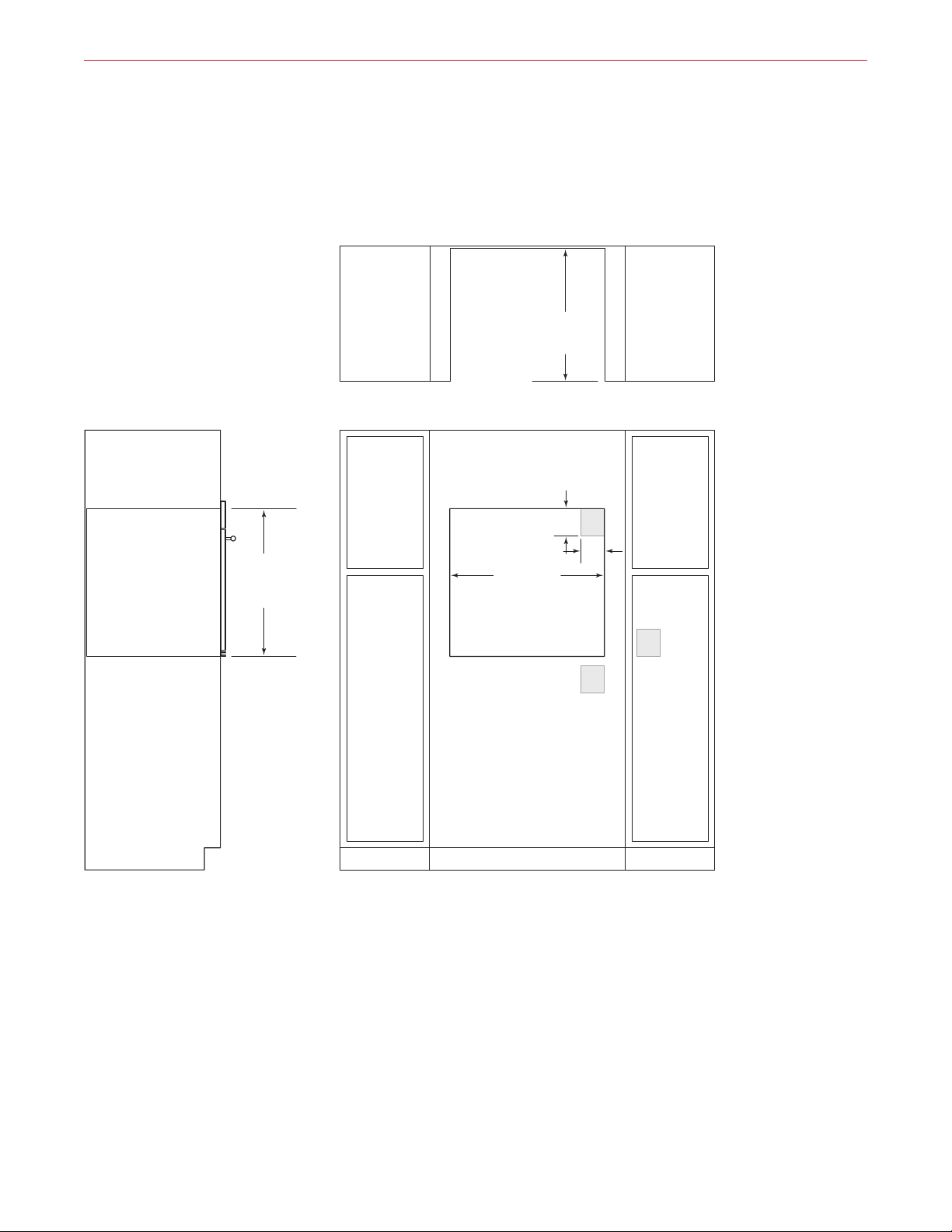
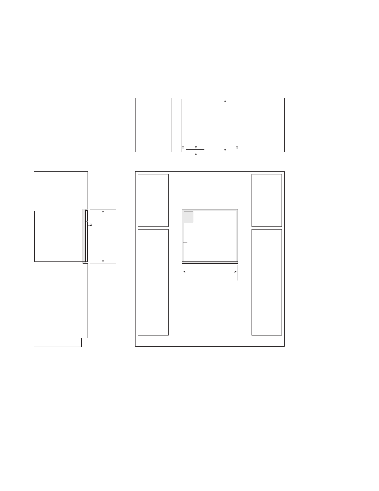
NOTE: Location of electrical supply within opening may require additional cabinet depth.
M Series Ovens
30" M Series Single Oven
STANDARD INSTALLATION
231/4" (591)
TOP VIEW
OPENING
DEPTH
VIEW
271/2"
(699)
OPENING
HEIGHT
281/2" (724)
OPENING WIDTH
FRONT VIEW
5"
(127)
E
4"
(102)
E
E
10 | Wolf Customer Care 800.222.7820
Page 11
*1
**
**
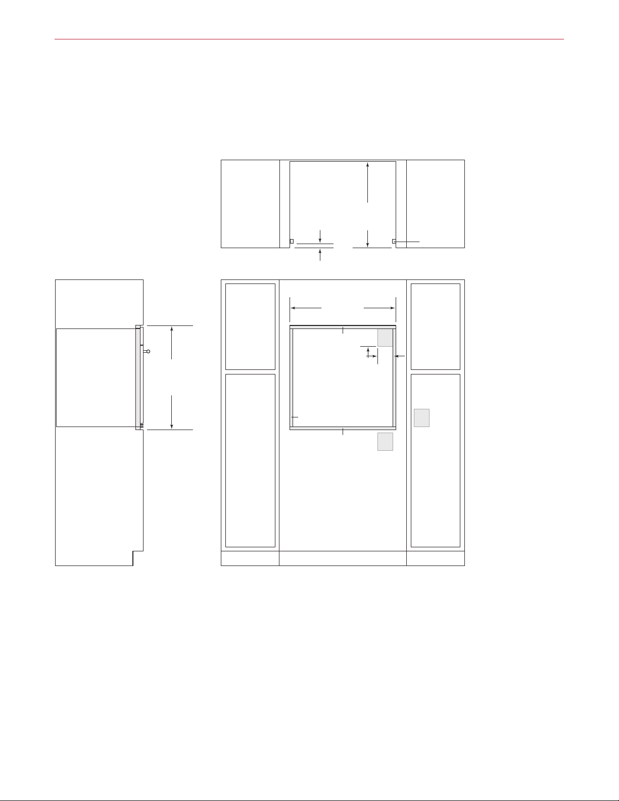
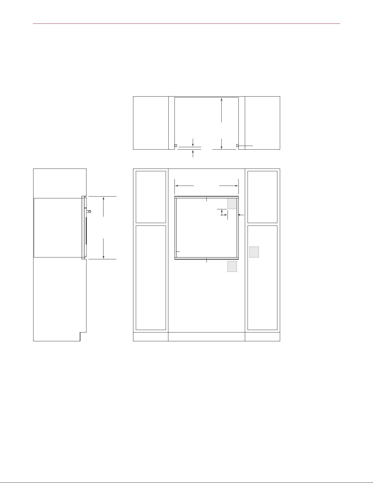
NOTE: Location of electrical supply within opening may require additional cabinet depth.
SIDE
M Series Ovens
30" M Series Single Oven
FLUSH INSET INSTALLATION
283/4"
(730)
FLUSH INSET
HEIGHT***
7
(22)
/8"
OR
(25)**
1"
FLUSH INSET WIDTH***
24" (610)
FLUSH INSET
TOP VIEW
301/8" (765)
DEPTH
11/8" (29)
13
/16" (21)
1
/8" (3)
5"
(127)
E
4"
(102)
E
FINISHED
CLEATS*
E
VIEW
" (25) minimum depth. Shaded areas will be visible and should be finished to match cabinetry.
7
/8" (22) for transitional, professional and contemporary stainless steel models and 1" (25) for contemporary black glass model.
*Dimension provides minimum reveals.
FRONT VIEW
wolfappliance.com | 11
Page 12
SIDE
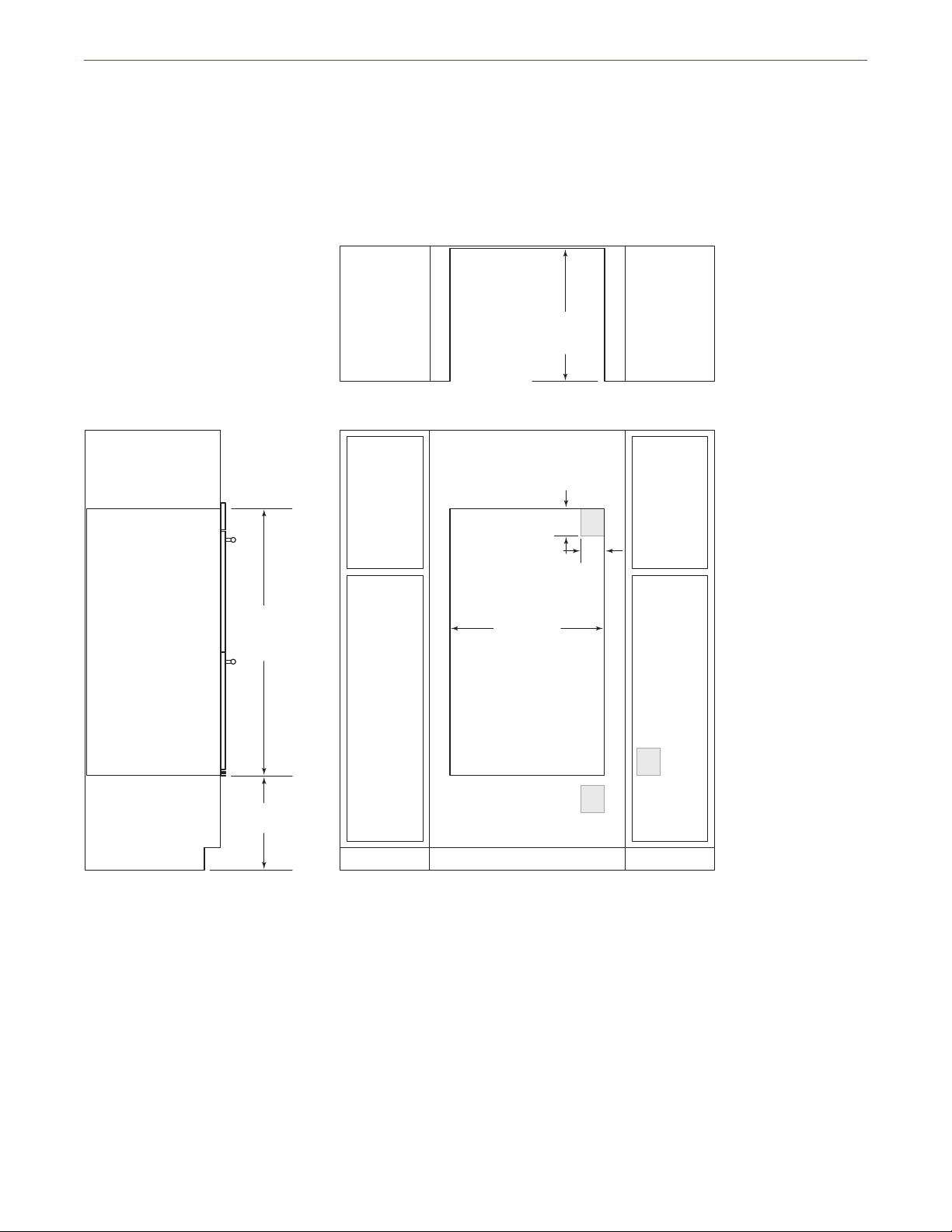
NOTE: Location of electrical supply within opening may require additional cabinet depth.
M Series Ovens
30" M Series Double Oven
STANDARD INSTALLATION
231/4" (591)
TOP VIEW
OPENING
DEPTH
VIEW
497/8"
(1267)
OPENING
HEIGHT
17" (432)
TYPICAL
281/2" (724)
OPENING WIDTH
FRONT VIEW
5"
(127)
E
4"
(102)
E
E
12 | Wolf Customer Care 800.222.7820
Page 13
*1
**
**
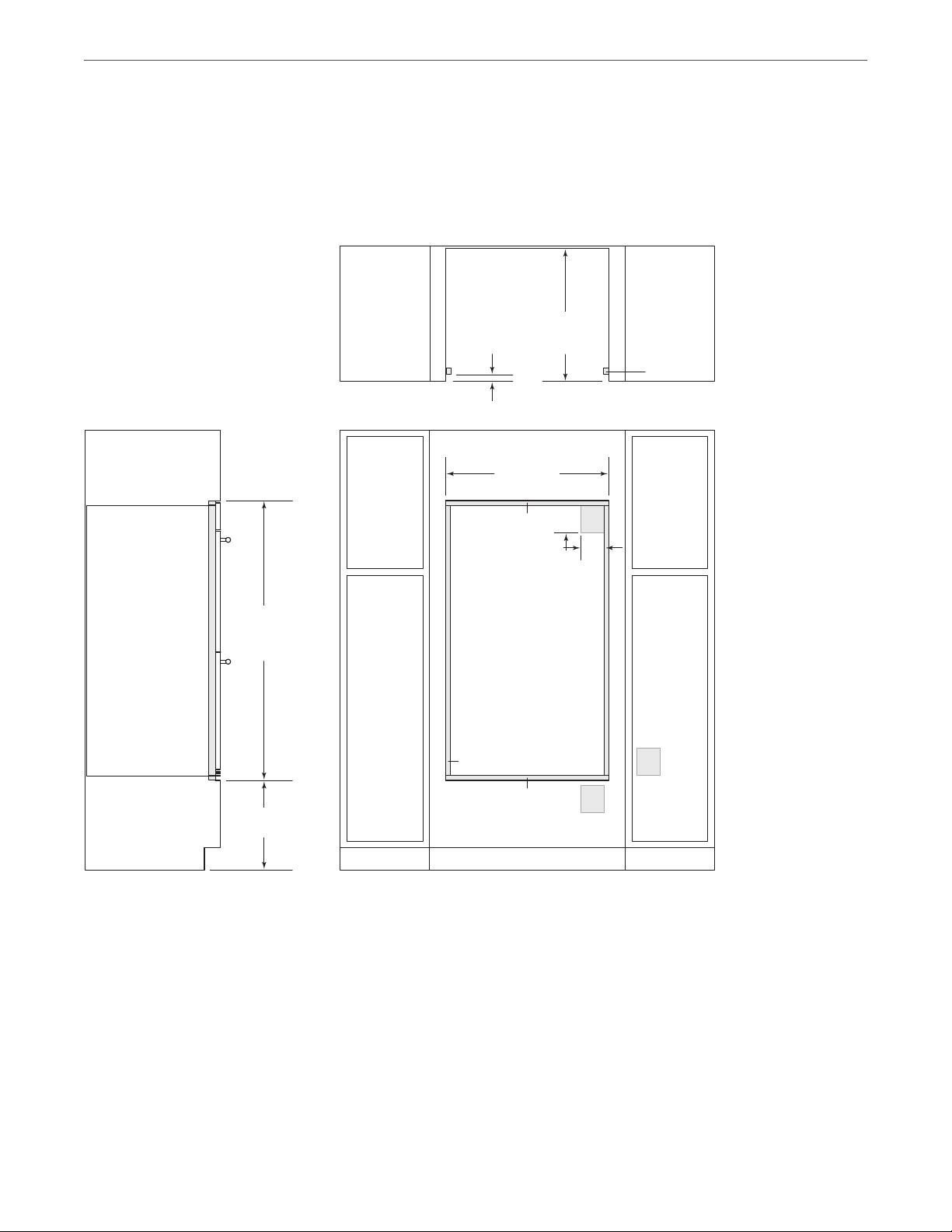
NOTE: Location of electrical supply within opening may require additional cabinet depth.
SIDE
M Series Ovens
30" M Series Double Oven
FLUSH INSET INSTALLATION
511/8"
(1299)
FLUSH INSET
HEIGHT***
7
(22)
/8"
OR
(25)**
1"
FLUSH INSET WIDTH***
24" (610)
FLUSH INSET
TOP VIEW
301/8" (765)
DEPTH
11/8" (29)
13
/16" (21)
5"
(127)
E
4"
(102)
FINISHED
CLEATS*
E
(432)
17"
TYPICAL
VIEW
" (25) minimum depth. Shaded areas will be visible and should be finished to match cabinetry.
7
/8" (22) for transitional, professional and contemporary stainless steel models and 1" (25) for contemporary black glass model.
*Dimension provides minimum reveals.
1
/8" (3)
FRONT VIEW
E
wolfappliance.com | 13
Page 14

SIDE
NOTE: Location of electrical supply within opening may require additional cabinet depth. A dual installation kit is required fo
M Series Ovens
30" M Series Single Oven
DUAL STANDARD INSTALLATION
TOP VIEW
231/4" (591)
OPENING
DEPTH
VIEW
271/2"
(699)
OPENING
HEIGHT
5"
E
(127)
4"
(102)
581/2" (1486)
OPENING WIDTH
E E
FRONT VIEW
r this installation.
5"
(127)
E
4"
(102)
14 | Wolf Customer Care 800.222.7820
Page 15
SIDE
*1
**
**
NOTE: Location of electrical supply within opening may require additional cabinet depth. A dual installation kit is required fo
M Series Ovens
30" M Series Single Oven
DUAL FLUSH INSET INSTALLATION
283/4"
(730)
FLUSH INSET
HEIGHT***
7
1"
13
/16" (21)
(22)
/8"
OR
(25)**
11/8" (29)
1
/8" (3)
TOP VIEW
601/8" (1527)
FLUSH INSET WIDTH***
5"
E
(127)
4"
(102)
24" (610)
FLUSH INSET
DEPTH
5"
(127)
(102)
FINISHED
CLEATS*
E
4"
EE
VIEW
" (25) minimum depth. Shaded areas will be visible and should be finished to match cabinetry.
7
/8" (22) for transitional, professional and contemporary stainless steel models and 1" (25) for contemporary black glass model.
*Dimension provides minimum reveals.
FRONT VIEW
r this installation.
wolfappliance.com | 15
Page 16
E Series Ovens
E Series Built-In Ovens
Wolf E series ovens are crafted of stainless steel.
The handles match the rest of the Wolf cooking
appliance oering, providing a more cohesive
look. E series ovens can be installed in a standard or flush inset application.
E SERIES OVENS
TRANSITIONAL
SO24TE/S/TH
PROFESSIONAL
SO30PE/S/PH
CONTEMPORARY
SO30TE/S/TH
DO30TE/S/TH
DO30PE/S/PH
16 | Wolf Customer Care 800.222.7820
SO30CE/B/TH
DO30CE/B/TH
Page 17
E Series Ovens
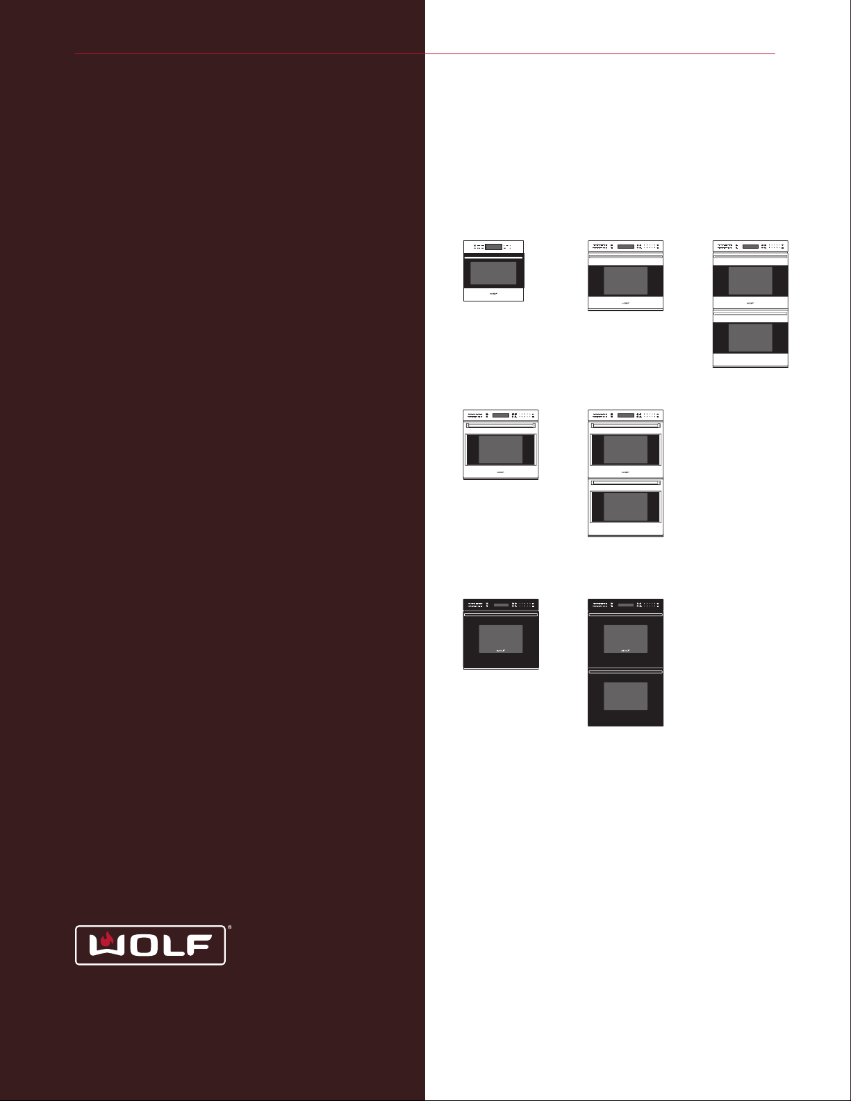
24" E Series Built-In Oven
TRANSITIONAL SINGLE OVEN
7
(22)
/8"
22"
(559)
231/2"
(597)
231/2"
(597)
21/2"
(64)
211/2" (546)
BEHIND FRAME
231/4"
(591)
OPEN OVEN DOOR
181/8"
(460)
wolfappliance.com | 17
Page 18
E Series Ovens
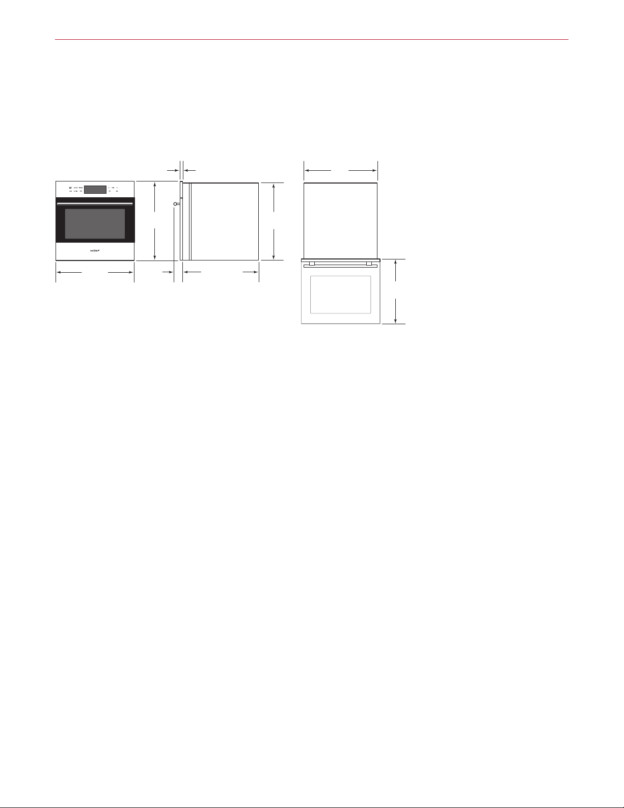
30" E Series Built-In Ovens
TRANSITIONAL SINGLE OVEN
1" (25)
277/8"
(708)
297/8"
(759)
23/4"
(70)
TRANSITIONAL DOUBLE OVEN
1" (25)
503/8"
(1280)
(76)
3"
CONDUIT
CHANNEL
233/4" (603)
BEHIND FRAME
(76)
3"
CONDUIT
CHANNEL
271/8"
(689)
495/8"
(1261)
87/8"
(225)
281/4"
(718)
OPEN OVEN DOOR
87/8"
(225)
281/4"
(718)
95/8"
(244)
95/8"
(244)
22"
(559)
297/8"
(759)
23/4"
(70)
18 | Wolf Customer Care 800.222.7820
233/4" (603)
BEHIND FRAME
OPEN OVEN DOOR
22"
(559)
Page 19
E Series Ovens
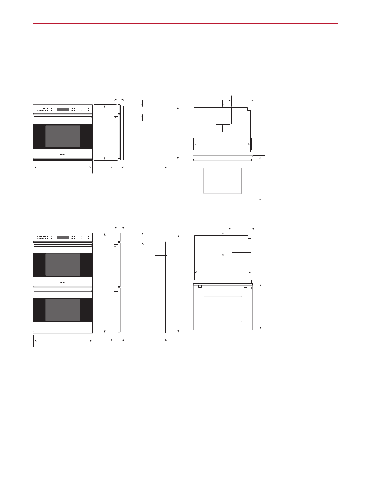
30" E Series Built-In Ovens
PROFESSIONAL SINGLE OVEN
1" (25)
277/8"
(708)
297/8"
(759)
33/8"
(86)
PROFESSIONAL DOUBLE OVEN
1" (25)
503/8"
(1280)
(76)
3"
CONDUIT
CHANNEL
233/4" (603)
BEHIND FRAME
(76)
3"
CONDUIT
CHANNEL
271/8"
(689)
495/8"
(1261)
87/8"
(225)
281/4"
(718)
OPEN OVEN DOOR
87/8"
(225)
281/4"
(718)
95/8"
(244)
95/8"
(244)
22"
(559)
297/8"
(759)
33/8"
(86)
233/4" (603)
BEHIND FRAME
OPEN OVEN DOOR
22"
(559)
wolfappliance.com | 19
Page 20
E Series Ovens
30" E Series Built-In Ovens
CONTEMPORARY SINGLE OVEN
(32)
11/4"
277/8"
(708)
(76)
3"
CONDUIT
CHANNEL
271/16"
(687)
87/8"
(225)
281/4"
(718)
95/8"
(244)
297/8"
(759)
3"
(76)
CONTEMPORARY DOUBLE OVEN
11/4" (32)
503/8"
(1280)
297/8"
(759)
3"
(76)
233/4" (603)
BEHIND FRAME
(76)
3"
CONDUIT
CHANNEL
233/4" (603)
BEHIND FRAME
491/2"
(1257)
OPEN OVEN DOOR
87/8"
(225)
281/4"
(718)
OPEN OVEN DOOR
95/8"
(244)
22"
(559)
22"
(559)
20 | Wolf Customer Care 800.222.7820
Page 21

E Series Ovens
Planning Information
E series ovens can be installed in a standard or flush inset
application. If a cooktop is being installed above an oven, a
minimum of ⁄"
(6) is required between the units. The loca-
tion of the electrical supply within the oven opening may
require additional cabinet depth.
Finish the edges of the opening. They may be visible when
the door is open.
For standard installations, the face trim will overlap stiles
and rails. Refer to the chart below.
For flush inset installations, a minimum reveal is required
on all sides. Refer to the chart below. To ensure consistent
reveals, each corner of the opening must be exactly 90°.
INSTALLATION REQUIREMENTS
BASE SUPPORT MIN
24" Oven 150 lb (68 kg)
30" Single Oven 250 lb (113 kg)
30" Double Oven 400 lb (181 kg)
TRIM OVERLAP 24" OVEN 30" OVEN
Top ⁄" (6) ⁄" (13)
Bottom 0" (0) ⁄" (3)
Sides ⁄" (17) ⁄" (17)
REVEAL MIN
24" Oven ⁄" (3)
30" Oven ⁄" (6)
wolfappliance.com | 21
Page 22
E Series Ovens
Electrical Requirements
24" OVEN
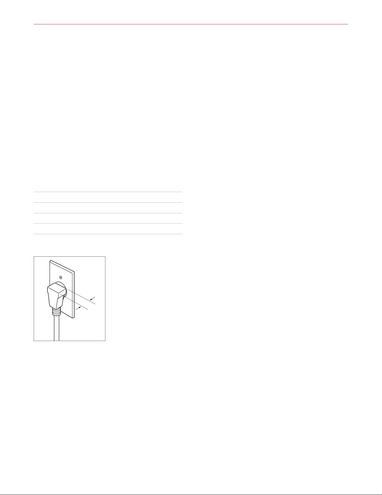
Installation must comply with all applicable electrical codes.
Locate the electrical supply as shown in the illustrations
on the following pages. A separate circuit servicing only
this appliance is required. A ground fault circuit interrupter
(GFCI) is not recommended and may cause interruption
of operation. Refer to the illustration below for minimum
power cord plug clearance.
Performance may be compromised if the electrical supply
is less than 240 volts.
ELECTRICAL REQUIREMENTS—24" OVEN
Electrical Supply grounded, 240/208 VAC, 60 Hz
Service 20 amp dedicated circuit
Receptacle NEMA 6-20R grounding-type
Power Cord 6' (1.8 m)
1" (25)
MINIMUM
CORD
CLEARANCE
Power cord clearance
22 | Wolf Customer Care 800.222.7820
Page 23

E Series Ovens
Electrical Requirements
30" OVEN
Installation must comply with all applicable electrical codes.
Locate the electrical supply flush with the back wall and
within the shaded area shown in the illustrations on the
following pages. For ease of installation, the electrical
supply for the oven can be placed in an adjacent cabinet
within reach of the conduit.
Performance may be compromised if the electrical supply
is less than 240 volts.
The oven is supplied with a conduit consisting of two
insulated hot lead conductors and a bare ground conductor. The wiring diagram covering the control circuit is
provided with the oven.
ELECTRICAL REQUIREMENTS—30" SINGLE OVEN
Electrical Supply grounded, 240/208 VAC, 60 Hz
Service 30 amp dedicated circuit
Conduit 4' (1.2 m)
Total Amps 21
Max Connected Load 5.1 kW
ELECTRICAL REQUIREMENTS—30" DOUBLE OVEN
Electrical Supply grounded, 240/208 VAC, 60 Hz
Service 50 amp dedicated circuit
Conduit 5' (1.5 m)
Total Amps 37
Max Connected Load 8.9 kW
wolfappliance.com | 23
Page 24
SIDE
E Series Ovens
24" E Series Single Oven
STANDARD INSTALLATION
23" (584)
OPENING
TOP VIEW
DEPTH
VIEW
231/4"
(591)
OPENING
HEIGHT
E
221/8" (562)
OPENING WIDTH
FRONT VIEW
24 | Wolf Customer Care 800.222.7820
Page 25
SIDE
*W
**
E Series Ovens
24" E Series Single Oven
FLUSH INSET INSTALLATION
7
/8" (22)
TOP VIEW
24" (610)
FLUSH
INSET
DEPTH
FINISHED
CLEATS*
233/4" (603)
FLUSH INSET
HEIGHT**
VIEW
ill be visible and should be finished to match cabinetry.
Dimension provides minimum reveals.
3
E
/8" (10)
13
/16" (21)
1
/8" (3)
233/4" (603)
FLUSH INSET WIDTH**
FRONT VIEW
wolfappliance.com | 25
Page 26

SIDE
NOTE: Location of electrical supply within opening may require additional cabinet depth.
E Series Ovens
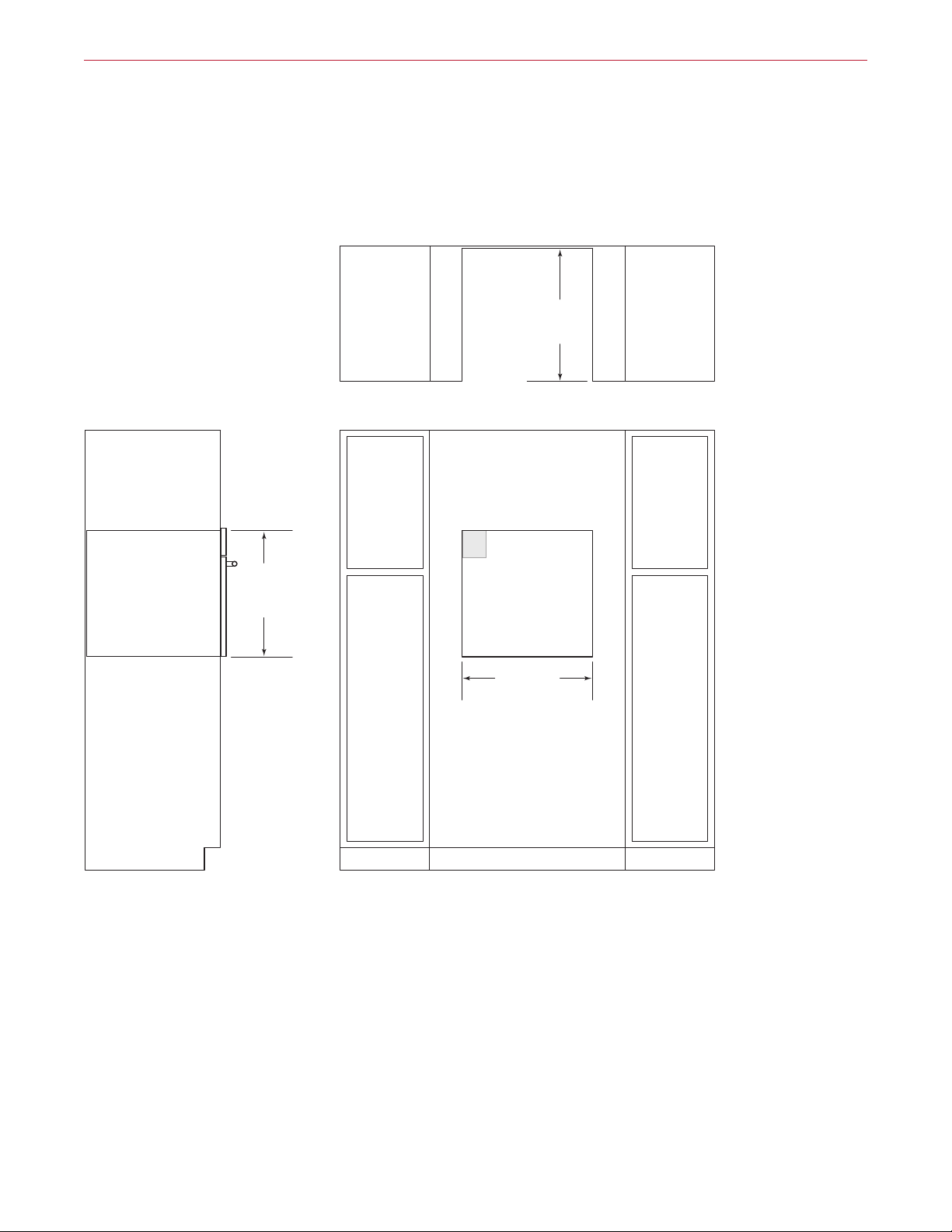
30" E Series Single Oven
STANDARD INSTALLATION
TOP VIEW
24" (610)
OPENING
DEPTH
VIEW
271/4"
(692)
OPENING
HEIGHT
(724)
281/2"
OPENING WIDTH
FRONT VIEW
5"
(127)
E
4"
(102)
E
E
26 | Wolf Customer Care 800.222.7820
Page 27
SIDE
*W
**
**
NOTE: Location of electrical supply within opening may require additional cabinet depth.
E Series Ovens
30" E Series Single Oven
FLUSH INSET INSTALLATION
1" (25)
OR
11/4" (32)**
FLUSH INSET WIDTH***
FLUSH INSET
TOP VIEW
303/8" (772)
25"
DEPTH
(635)
FINISHED
CLEATS*
283/8"
(721)
FLUSH INSET
HEIGHT***
15
VIEW
ill be visible and should be finished to match cabinetry.
1" (25) for professional and transitional models and 11/4" (32) for contemporary model.
*Dimension provides minimum reveals.
(24)
/16"
FRONT VIEW
3
/4"(19)
3
/8" (10)
5"
(127)
E
4"
(102)
E
E
wolfappliance.com | 27
Page 28

SIDE
NOTE: Location of electrical supply within opening may require additional cabinet depth.
E Series Ovens
30" E Series Double Oven
STANDARD INSTALLATION
TOP VIEW
24" (610)
OPENING
DEPTH
VIEW
493/4"
(1264)
OPENING
HEIGHT
17" (432)
TYPICAL
281/2" (724)
OPENING WIDTH
FRONT VIEW
5"
(127)
E
4"
(102)
E
E
28 | Wolf Customer Care 800.222.7820
Page 29

SIDE
*W
**
**
NOTE: Location of electrical supply within opening may require additional cabinet depth.
E Series Ovens
30" E Series Double Oven
FLUSH INSET INSTALLATION
507/8"
(1292)
FLUSH INSET
HEIGHT***
1" (25)
OR
11/4" (32)**
FLUSH INSET WIDTH***
15
/16" (24)
FLUSH INSET
TOP VIEW
303/8" (772)
3
/4"(19)
25" (635)
DEPTH
5"
(127)
E
4"
(102)
FINISHED
CLEATS*
E
17" (432)
TYPICAL
VIEW
ill be visible and should be finished to match cabinetry.
1" (25) for professional and transitional models and 11/4" (32) for contemporary model.
*Dimension provides minimum reveals.
3
/8" (10)
FRONT VIEW
E
wolfappliance.com | 29
Page 30

L Series Oven
L Series Built-In Oven
Since their introduction, Wolf L series built-in
ovens have taken the culinary world by storm—
and not just for their stylish cobalt blue interior
and 10 cooking modes. Thanks to a Wolf innovation called dual convection, the L series delivers faster, more consistent results for baking,
roasting, broiling—even drying fruits. The Wolf
L series oven is oered in the 36" width with
unframed door style and tubular handle.
L SERIES OVEN
UNFRAMED
SO36U/S
30 | Wolf Customer Care 800.222.7820
Page 31

L Series Oven
L Series Built-In Oven
DIMENSIONS
355/8"
(905)
243/8"
(619)
3"
(76)
(76)
3"
CONDUIT
CHANNEL
24" (610)
BEHIND FRAME
23"
(584)
87/8"
(225)
341/8"
(867)
OPEN OVEN DOOR
95/8"
(244)
173/4"
(451)
wolfappliance.com | 31
Page 32

L Series Oven
Planning Information
If a cooktop is being installed above an oven, a minimum
(6) is required between the units. The location of
of ⁄"
the electrical supply within the oven opening may require
additional cabinet depth.
Finish the edges of the opening. They may be visible when
the door is open.
For standard installations, the face trim will overlap stiles
and rails. Refer to the chart below.
INSTALLATION REQUIREMENTS
BASE SUPPORT MIN
36" Single Oven 250 lb (113 kg)
TRIM OVERLAP
Top ⁄" (5)
Bottom ⁄" (3)
Sides ⁄" (14)
ELECTRICAL REQUIREMENTS
Installation must comply with all applicable electrical codes.
Locate the electrical supply flush with the back wall and
within the shaded area shown in the illustration on the following page. For ease of installation, the electrical supply
for the oven can be placed in an adjacent cabinet within
reach of the conduit.
Performance may be compromised if the electrical supply
is less than 240 volts.
The oven is supplied with a conduit consisting of two
insulated hot lead conductors and a bare ground conductor. The wiring diagram covering the control circuit is
provided with the oven.
ELECTRICAL REQUIREMENTS
Electrical Supply grounded, 240/208 VAC, 60 Hz
Service 30 amp dedicated circuit
Conduit 3' (.9 m)
Total Amps 21
Max Connected Load 5.1 kW
32 | Wolf Customer Care 800.222.7820
Page 33

SIDE
NOTE: Location of electrical supply within opening may require additional cabinet depth.
L Series Oven
36" L Series Single Oven
STANDARD INSTALLATION
TOP VIEW
24" (610)
OPENING
DEPTH
VIEW
241/16"
(611)
OPENING
HEIGHT
341/2" (876)
OPENING WIDTH
FRONT VIEW
5"
(127)
E
4"
(102)
E
E
wolfappliance.com | 33
Page 34

Convection Steam Ovens
Convection Steam Ovens
The legacy of the “combination oven” goes
back decades, to innovative chefs in America
and Europe who embraced the combination
of air movement with superheated steam to
achieve superior results—from breads and roasts
to delicate fishes, seafood, and vegetables.
Wolf combines the benefits of convection and
steam for the most innovative steam oven on
the market today. Virtually any dish prepared in
a conventional oven, range, or microwave can
also be prepared in the Wolf convection steam
oven—with more control. Two widths and three
distinct styles compliment the look of Wolf
ovens, ranges, and cooktops. Convection steam
ovens can be installed in a standard or flush inset
application.
CONVECTION STEAM OVENS
TRANSITIONAL
CSO24TE/S/TH
PROFESSIONAL
CSO30PM/S/PH
CONTEMPORARY
CSO30CM/B/TH
CSO30TM/S/TH
CSO30PE/S/PH
CSO30CMS
CSO30TE/S/TH
CSO30CMB
34 | Wolf Customer Care 800.222.7820
Page 35

Convection Steam Ovens
Convection Steam Ovens
TRANSITIONAL
7
/8"
(22)
171/2"
W
WIDTH
177/8"
(454)
21/2"
(64)
211/2" (546)
BEHIND FRAME
WIDTH W
24" Transitional 23⁄" (597)
30" Transitional 29⁄" (759)
(446)
213/16"
(538)
OPEN OVEN DOOR
143/16"
(360)
wolfappliance.com | 35
Page 36

Convection Steam Ovens
Convection Steam Ovens
PROFESSIONAL
297/8"
(759)
CONTEMPORARY
297/8"
(759)
177/8"
(454)
31/4"
(83)
177/8"
(454)
21/2"
(64)
7
/8"
(22)
211/2" (546)
BEHIND FRAME
7
/8"
(22)
211/2" (546)
BEHIND FRAME
171/2"
(446)
171/2"
(446)
213/16"
(538)
OPEN OVEN DOOR
213/16"
(538)
143/16"
(360)
OPEN OVEN DOOR
143/16"
(360)
36 | Wolf Customer Care 800.222.7820
Page 37

Convection Steam Ovens
Planning Information
The convection steam oven can be installed in a standard
or flush inset application.
Finish the edges of the opening. They may be visible when
the door is open.
For standard installations, the face trim will overlap stiles
and rails. Refer to the chart below.
For flush inset installations, a minimum ⁄"
(3) reveal is
required on all sides. To ensure consistent reveals, each
corner of the opening must be exactly 90°.
INSTALLATION REQUIREMENTS
BASE SUPPORT MIN
Convection Steam Oven 100 lb (45 kg)
TRIM OVERLAP 24" MODEL 30" MODEL
Top ⁄" (5) ⁄" (5)
Bottom 0" (0) 0" (0)
Sides ⁄" (18) 3⁄" (98)
ELECTRICAL REQUIREMENTS
Installation must comply with all applicable electrical codes.
Locate the electrical supply as shown in the illustrations
on the following pages. A separate circuit servicing only
this appliance is required. A ground fault circuit interrupter
(GFCI) is not recommended and may cause interruption
of operation. Refer to the illustration below for minimum
power cord plug clearance.
Performance may be compromised if the electrical supply
is less than 240 volts.
ELECTRICAL REQUIREMENTS
Electrical Supply grounded, 240/208 VAC, 60 Hz
Service 20 amp dedicated circuit
Receptacle NEMA 6-20R grounding-type
Power Cord 6' (1.8 m)
1" (25)
MINIMUM
CLEARANCE
Power cord clearance
CORD
wolfappliance.com | 37
Page 38

SIDE
NOTE: 24"
Convection Steam Ovens
Convection Steam Oven
STANDARD INSTALLATION
23" (584)
OPENING
TOP VIEW
DEPTH
1711/16"
(449)
OPENING
HEIGHT
VIEW
(610) and 30" (762) models require the same opening dimensions.
OPENING WIDTH W
24" Model 22⁄" (562)
30" Model 22⁄" (562)
E
OPENING WIDTH
FRONT VIEW
W
38 | Wolf Customer Care 800.222.7820
Page 39

SIDE
*W
**
Convection Steam Ovens
Convection Steam Oven
FLUSH INSET INSTALLATION
7
/8"
(22)
TOP VIEW
24" (610)
FLUSH INSET
DEPTH
FINISHED
CLEATS*
181/8"
(460)
FLUSH INSET
HEIGHT**
VIEW
ill be visible and should be finished to match cabinetry.
Dimension provides minimum reveals.
FLUSH INSET WIDTH W A
24" Model 23⁄" (603) ⁄" (21)
30" Model 30⁄" (765) 4" (102)
5
E
/16"(8)
A
1
/8" (3)
W
FLUSH INSET WIDTH**
FRONT VIEW
wolfappliance.com | 39
Page 40

Speed Ovens
Speed Ovens
The Wolf speed oven has features that make
fast meals better meals. Available in 24" and 30"
widths, they are designed to match Wolf transitional, professional, and contemporary products.
The speed oven can be installed in a standard or
flush inset application.
SPEED OVENS
TRANSITIONAL
SPO24TE/S/TH
PROFESSIONAL
SPO30PM/S/PH
CONTEMPORARY
SPO30CM/B/TH
SPO30TM/S/TH
SPO30PE/S/PH
SPO30TE/S/TH
40 | Wolf Customer Care 800.222.7820
Page 41

Speed Ovens
Speed Ovens
TRANSITIONAL
7
(22)
/8"
213/16"
(538)
171/2"
W
WIDTH
177/8"
(454)
21/2"
(64)
211/2" (546)
BEHIND FRAME
WIDTH W
24" Transitional 23⁄" (597)
30" Transitional 29⁄" (759)
(446)
OPEN
OVEN DOOR
143/16"
(360)
wolfappliance.com | 41
Page 42

Speed Ovens
Speed Ovens
PROFESSIONAL
297/8"
(759)
CONTEMPORARY
297/8"
(759)
177/8"
(454)
31/4"
(83)
177/8"
(454)
21/2"
(64)
7
/8"
(22)
211/2" (546)
BEHIND FRAME
7
/8"
(22)
211/2" (546)
BEHIND FRAME
171/2"
(446)
171/2"
(446)
213/16"
(538)
OPEN
OVEN DOOR
213/16"
(538)
143/16"
(360)
OPEN
OVEN DOOR
143/16"
(360)
42 | Wolf Customer Care 800.222.7820
Page 43

Speed Ovens
Planning Information
The speed oven can be installed in a standard or flush inset
application.
Finish the edges of the opening. They may be visible when
the door is open.
For standard installations, the face trim will overlap stiles
and rails. Refer to the chart below.
For flush inset installations, a minimum ⁄"
(3) reveal is
required on all sides. To ensure consistent reveals, each
corner of the opening must be exactly 90°.
If the speed oven is installed above or below a Wolf E
series oven in a flush inset application, a ⁄"
(6) reveal is
required.
INSTALLATION REQUIREMENTS
BASE SUPPORT MIN
24" (610) Model 125 lb (57 kg)
30" (762) Model 125 lb (57 kg)
TRIM OVERLAP 24" MODEL 30" MODEL
Top ⁄" (5) ⁄" (5)
Bottom 0" (0) 0" (0)
Sides ⁄" (18) 3⁄" (98)
ELECTRICAL REQUIREMENTS
Installation must comply with all applicable electrical codes.
Locate the electrical supply as shown in the illustrations on
the following pages. The receptacle may also be located
in an adjacent cabinet within reach of the power cord. A
separate circuit, servicing only this appliance is required. A
ground fault circuit interrupter (GFCI) is not recommended
and may cause interruption of operation. Refer to the illustration below for minimum power cord plug clearance.
ELECTRICAL REQUIREMENTS
Electrical Supply grounded, 240/208 VAC, 60 Hz
Service 15 amp dedicated circuit
Receptacle NEMA 6-20R grounding type
Power Cord 6' (1.8 m)
NEMA
PLUG
GROUNDED
NEMA RECEPTACLE
NEMA 6-20R receptacle
1" (25)
MINIMUM
CLEARANCE
Power cord clearance
CORD
wolfappliance.com | 43
Page 44

SIDE
NOTE: 24"
Speed Ovens
Speed Oven
STANDARD INSTALLATION
23" (584)
OPENING
TOP VIEW
DEPTH
1711/16"
(449)
OPENING
HEIGHT
VIEW
(610) and 30" (762) models require the same opening dimensions.
OPENING WIDTH W
24" Model 22⁄" (562)
30" Model 22⁄" (562)
E
OPENING WIDTH
FRONT VIEW
W
44 | Wolf Customer Care 800.222.7820
Page 45

SIDE
*W
**
Speed Ovens
Speed Oven
FLUSH INSET INSTALLATION
7
/8"
(22)
TOP VIEW
24" (610)
FLUSH INSET
DEPTH
FINISHED
CLEATS*
181/8"
(460)
FLUSH INSET
HEIGHT**
VIEW
ill be visible and should be finished to match cabinetry.
Dimension provides minimum reveals.
FLUSH INSET WIDTH W A
24" Model 23⁄" (603) ⁄" (21)
30" Model 30⁄" (765) 4" (102)
5
E
/16"(8)
A
1
/8" (3)
W
FLUSH INSET WIDTH**
FRONT VIEW
wolfappliance.com | 45
Page 46

Microwave Ovens
Microwave Ovens
As true cooking instruments, Wolf microwave
ovens have features that make fast meals better
meals. The drop-down door microwaves feature a door that hinges at the bottom for easier
access to foods. Available in 24" and 30" widths,
they are designed to match Wolf transitional,
professional, and contemporary products.
Drawer microwave ovens can be conveniently
located undercounter, in a corner, or below an
oven. Wolf also oers both a roomy, powerful
standard microwave and a convection model
that can microwave, broil, and cook in three
convection modes. Trim kits to match Wolf
ovens are available through an authorized Wolf
dealer. Microwave ovens can be installed in a
standard or flush inset application.
DROP-DOWN DOOR MICROWAVES
TRANSITIONAL
MDD24TE/S/TH
PROFESSIONAL
MDD30PM/S/PH
CONTEMPORARY
MDD30CM/B/TH
MDD30TM/S/TH
MDD30PE/S/PH
DRAWER MICROWAVE
TRANSITIONAL
MDD30TE/S/TH
MD24TE/S
PROFESSIONAL
MD30PE/S
MD30TE/S
CONVECTION MICROWAVE
MC24 (M/E TRIM)
MC24 (L TRIM)
STANDARD MICROWAVE
MS24 (M/E TRIM)
MS24 (L TRIM)
46 | Wolf Customer Care 800.222.7820
Page 47

Microwave Ovens
Drop-Down Door Microwave Ovens
TRANSITIONAL
7
/8"
(22)
213/16"
(538)
171/2"
W
WIDTH
177/8"
(454)
21/2"
(64)
20" (508)
BEHIND FRAME
WIDTH W
24" Transitional 23⁄"
(597)
30" Transitional 29⁄" (759)
PROFESSIONAL
7
/8"
(22)
171/2"
297/8"
(759)
177/8"
(454)
31/4"
(83)
20" (508)
BEHIND FRAME
(446)
(446)
OPEN
OVEN DOOR
213/16"
(538)
143/16"
(360)
CONTEMPORARY
297/8"
(759)
177/8"
(454)
21/2"
(64)
7
/8"
(22)
20" (508)
BEHIND FRAME
171/2"
(446)
OPEN
OVEN DOOR
213/16"
(538)
OPEN
OVEN DOOR
143/16"
(360)
143/16"
(360)
wolfappliance.com | 47
Page 48

Microwave Ovens
Drawer Microwave Ovens
TRANSITIONAL / PROFESSIONAL
11/4"
(32)
151/8"
(384)
297/8" (759)
217/8" (556)
BEHIND FRAME
WIDTH W
24" Model 23⁄" (606)
30" Model 29⁄" (759)
13/4"
POWER CORD
(45)
CHANNEL
145/8"
(372)
215/8" (549)
45/8"
(118)
OPEN DRAWER
161/2"
(419)
48 | Wolf Customer Care 800.222.7820
Page 49

*1
TRIM WIDTH
133/8"
(340)
FREE-
STANDING
24" (610)
FREESTANDING
181/4"
(464)
WITH
TRIM
18" (457)
BEHIND TRIM
*11/4" (32) for contemporary E series trim only.
1" (25) OR
11/4" (32)*
*1
147/8"
(378)
FREE-
STANDING
243/4" (629)
FREESTANDING
197/8"
(505)
WITH
TRIM
TRIM WIDTH
18" (457)
BEHIND TRIM
*11/4" (32) for contemporary E series trim only.
1" (25) OR
11/4" (32)*
Microwave Ovens
Convection Microwave Oven
M/E SERIES TRIM
243/4" (629)
FREESTANDING
197/8"
(505)
WITH
TRIM
TRIM WIDTH
1
/4" (32) for contemporary E series trim only.
L SERIES TRIM
243/4" (629)
FREESTANDING
197/8"
(505)
WITH
TRIM
1" (25) OR
11/4" (32)*
(457)
18"
BEHIND TRIM
13/8"
(35)
147/8"
(378)
FREE-
STANDING
147/8"
(378)
FREE-
STANDING
Standard Microwave Oven
M/E SERIES TRIM
24" (610)
FREESTANDING
181/4"
(464)
WITH
TRIM
TRIM WIDTH
1
/4" (32) for contemporary E series trim only.
L SERIES TRIM
24" (610)
FREESTANDING
181/4"
(464)
WITH
TRIM
1" (25) OR
11/4" (32)*
18" (457)
BEHIND TRIM
13/8"
(35)
133/8"
(340)
FREE-
STANDING
133/8"
(340)
FREE-
STANDING
TRIM WIDTH
175/8" (448)
BEHIND TRIM
TRIM WIDTH M SERIES E SERIES L SERIES
27" Trim NA 26⁄" (683) NA
30" Trim 29⁄" (759) 29⁄" (759) 29⁄" (759)
36" Trim NA NA 35⁄" (905)
TRIM WIDTH
175/8" (448)
BEHIND TRIM
TRIM WIDTH M SERIES E SERIES L SERIES
27" Trim NA 26⁄" (683) NA
30" Trim 29⁄" (759) 29⁄" (759) 29⁄" (759)
wolfappliance.com | 49
Page 50

Microwave Ovens
Planning Information
DROP-DOWN DOOR MICROWAVE
The drop-down door microwave oven can be installed in a
standard or flush inset application.
Finish the edges of the opening. They may be visible when
the door is open.
For standard installations, the face trim will overlap stiles
and rails. Refer to the chart below.
For flush inset installations, a minimum ⁄"
(3) reveal is
required on all sides. To ensure consistent reveals, each
corner of the opening must be exactly 90°.
INSTALLATION REQUIREMENTS
BASE SUPPORT MIN
Drop-Down Door Microwave 125 lb (57 kg)
TRIM OVERLAP 24" MODEL 30" MODEL
Top ⁄" (5) ⁄" (5)
Bottom 0" (0) 0" (0)
Sides ⁄" (18) 3⁄" (98)
DRAWER MICROWAVE
The drawer microwave oven can be installed in a standard
or flush inset application. The location of the electrical
supply within the oven opening may require additional
cabinet depth.
Finish the edges of the opening. They may be visible when
the drawer is open.
For standard installations, the face trim will overlap stiles
and rails. Refer to the chart below.
For flush inset installations, a minimum ⁄"
required on the top and sides and ⁄" (18)
(3) reveal is
on the bottom. To
ensure consistent reveals, each corner of the opening
must be exactly 90°. A sales accessory is required to direct
air away from the unit. Accessories are available through
an authorized Wolf dealer. For local dealer information,
visit the find a showroom section of our website,
wolfappliance.com.
INSTALLATION REQUIREMENTS
BASE SUPPORT MIN
24" Drawer Microwave 125 lb (57 kg)
30" Drawer Microwave 125 lb (57 kg)
TRIM OVERLAP 24" MODEL 30" MODEL
Top ⁄" (8) ⁄" (8)
Bottom ⁄" (2) ⁄" (2)
Sides ⁄" (22) 3⁄" (98)
50 | Wolf Customer Care 800.222.7820
Page 51

Microwave Ovens
Planning Information
CONVECTION / STANDARD MICROWAVES
Convection and standard microwave ovens can be
installed in a standard or flush inset application using
accessory trim to match Wolf ovens. Trim kits are avail able
through an authorized Wolf dealer. For local dealer information, visit the find a showroom section of our website,
wolfappliance.com.
For standard installations, the face trim will overlap stiles
and rails. Refer to the chart below.
Convection and standard microwave ovens can also be
used freestanding. For freestanding applications, a minimum 2"
the microwave oven for air circulation.
INSTALLATION REQUIREMENTS
BASE SUPPORT MIN
Convection Microwave 125 lb (57 kg)
Standard Microwave 125 lb (57 kg)
27" E SERIES TRIM OVERLAP CONV STAN
Top ⁄" (6) ⁄" (14)
Bottom ⁄" (19) ⁄" (17)
Sides ⁄" (21) ⁄" (21)
30" M/E/L TRIM OVERLAP CONV STAN
Top ⁄" (6) ⁄" (14)
Bottom ⁄" (19) ⁄" (17)
Sides 1⁄" (30) 1⁄" (30)
36" L SERIES TRIM OVERLAP CONV STAN
Top ⁄" (5) NA
Bottom ⁄" (21) NA
Sides 1⁄" (32) NA
(51) space is required at the top, rear, and sides of
Electrical Requirements
Installation must comply with all applicable electrical codes.
Locate the electrical supply as shown in the illustrations on
the following pages. The receptacle may also be located
in an adjacent cabinet within reach of the power cord. A
separate circuit servicing only this appliance is required. A
ground fault circuit interrupter (GFCI) is not recommended
and may cause interruption of operation. Refer to the illustration below for minimum power cord plug clearance.
ELECTRICAL REQUIREMENTS
Electrical Supply grounded, 120 VAC, 60 Hz
Service 15 amp dedicated circuit
Receptacle 3-prong grounding-type
Power Cord 4' (1.2 m)
3"
(76)
MINIMUM CORD
CLEARANCE
Power cord clearance
wolfappliance.com | 51
Page 52

SIDE
NOTE: 24"
Microwave Ovens
Drop-Down Door Microwave Oven
STANDARD INSTALLATION
OPENING
TOP VIEW
219/16"
(548)
DEPTH
1711/16"
(449)
OPENING
HEIGHT
VIEW
(610) and 30" (762) models require the same opening dimensions.
OPENING WIDTH W
24" Model 22⁄" (562)
30" Model 22⁄" (562)
E
OPENING WIDTH
FRONT VIEW
W
52 | Wolf Customer Care 800.222.7820
Page 53

SIDE
*W
**
Microwave Ovens
Drop-Down Door Microwave Oven
FLUSH INSET INSTALLATION
7
/8"
(22)
TOP VIEW
23" (584)
FLUSH INSET
DEPTH
FINISHED
CLEATS*
181/8"
(460)
FLUSH INSET
HEIGHT**
VIEW
ill be visible and should be finished to match cabinetry.
Dimension provides minimum reveals.
FLUSH INSET WIDTH W A
24" Model 23⁄" (603) ⁄" (21)
30" Model 30⁄" (765) 4" (102)
5
E
/16"(8)
A
1
/8" (3)
W
FLUSH INSET WIDTH**
FRONT VIEW
wolfappliance.com | 53
Page 54

SIDE
NOTE: All dr
Microwave Ovens
Drawer Microwave Oven
STANDARD INSTALLATION
22" (559)
OPENING
DEPTH
TOP VIEW
ANTI-TIP BLOCK
143/4" (375)
OPENING
HEIGHT
VIEW
awer microwave ovens require the same opening dimensions.
OPENING WIDTH W
24" Model 22 1/8" (562)
30" Model 22 1/8" (562)
E
W
OPENING WIDTH
FRONT VIEW
54 | Wolf Customer Care 800.222.7820
Page 55

SIDE
*W
**
Microwave Ovens
Drawer Microwave Oven
FLUSH INSET INSTALLATION
11/4" (32)
231/4"
FLUSH INSET
TOP VIEW
DEPTH
(591)
FINISHED
CLEATS*
ANTI-TIP BLOCK
1515/16" (405)
FLUSH INSET
HEIGHT**
VIEW
ill be visible and should be finished to match cabinetry.
Dimension provides minimum reveals.
FLUSH INSET WIDTH W A
24" Model 24 1/8" (613) 1" (25)
30" Model 30 1/8" (765) 4" (102)
7
E
/16"(11)
A
3
/4" (19)
FLUSH INSET WIDTH**
W
FRONT VIEW
wolfappliance.com | 55
Page 56

SIDE
Microwave Ovens
Convection Microwave Oven
STANDARD INSTALLATION WITH TRIM
201/8" (511)
TOP VIEW
OPENING
DEPTH
187/8" (479)
OPENING
HEIGHT
VIEW
OPENING WIDTH W
27" Trim 25⁄" (641)
30" Trim 27⁄" (699)
36" Trim 33⁄" (854)
E
OPENING WIDTH
FRONT VIEW
W
56 | Wolf Customer Care 800.222.7820
Page 57

*W
**
**
SIDE
Microwave Ovens
Convection Microwave Oven
FLUSH INSET INSTALLATION WITH TRIM
201/8" (511)
FLUSH INSET
HEIGHT***
1" (25)
OR
(32)**
11/4"
TOP VIEW
3
E
/8"
A
7
/8" (22)
FLUSH INSET WIDTH***
231/4"
FLUSH INSET
DEPTH
(10)
W
(591)
FINISHED
CLEATS*
VIEW
ill be visible and should be finished to match cabinetry.
11/4" (32) for contemporary E series trim only.
*Dimension provides minimum reveals.
FLUSH INSET WIDTH W A
27" Trim 27⁄" (689) ⁄" (24)
30" Trim 30⁄" (765) 1⁄" (30)
FRONT VIEW
wolfappliance.com | 57
Page 58

SIDE
Microwave Ovens
Standard Microwave Oven
STANDARD INSTALLATION WITH TRIM
TOP VIEW
20" (508)
OPENING
DEPTH
17" (432)
OPENING
HEIGHT
VIEW
OPENING WIDTH W
27" Trim 25⁄" (641)
30" Trim 27⁄" (699)
E
OPENING WIDTH
FRONT VIEW
W
58 | Wolf Customer Care 800.222.7820
Page 59

SIDE
*W
**
**
Microwave Ovens
Standard Microwave Oven
FLUSH INSET INSTALLATION WITH TRIM
181/2" (470)
FLUSH INSET
HEIGHT***
1" (25)
OR
(32)**
11/4"
TOP VIEW
11
E
/16"
A
13
/16" (21)
FLUSH INSET WIDTH***
231/4"
FLUSH INSET
DEPTH
(17)
W
(591)
FINISHED
CLEATS*
VIEW
ill be visible and should be finished to match cabinetry.
11/4" (32) for contemporary E series trim only.
*Dimension provides minimum reveals.
FLUSH INSET WIDTH W A
27" Trim 27⁄" (689) ⁄" (24)
30" Trim 30⁄" (765) 1⁄" (30)
FRONT VIEW
wolfappliance.com | 59
Page 60

Warming Drawers
Warming Drawers
Wolf warming drawers are designed to take care
of prepared foods until it’s time to serve them.
You can adjust the temperature, keeping moist
foods moist, and crisp foods crisp. Warming
drawers are ideal for proofing dough. They can
also be used to warm robes and towels. Drawer
fronts are available to match the look of Wolf
ovens, sealed burner rangetops, and outdoor
grills. The integrated drawer front allows for a
custom panel and handle. Model WWD30O,
approved for outdoor installations, is ideal for
any outdoor kitchen.
WARMING DRAWER FRONTS
M/E SERIES
TRANSITIONAL
L SERIES
TRANSITIONAL
INTEGRATED
CUSTOM PANEL
PROFESSIONAL
CONTEMPORARY
60 | Wolf Customer Care 800.222.7820
Page 61

Warming Drawers
Warming Drawers
DRAWER FRONT OPTIONS
Wolf warming drawer fronts allow for many design options,
but the warming drawer itself will be the same for all applications. A panel mounting kit is required when installing a
custom panel. The panel mounting kit is available through
an authorized Wolf dealer. For local dealer information,
visit the find a showroom section of our website,
wolfappliance.com.
(51) thick drawer front, in 30" and 36" widths, is
The 2"
designed to be installed below a sealed burner rangetop
or outdoor gas grill, so the panel aligns properly with the
front of the rangetop or grill. Dimensions for the warming
drawer remain the same, even though the drawer front
may be wider to match a Wolf 36" oven, sealed burner
rangetop, or outdoor grill.
DIMENSIONS
W
WIDTH
281/4" (718)
OPEN DRAWER
103/8"
(264)
211/2"
(546)
B
A
223/4" (578)
9"
(229)
STAINLESS STEEL DRAWER FRONT
WIDTH W
30" Drawer Front 29⁄" (759)
36" Drawer Front 35⁄" (911)
M SERIES A B
Transitional/Professional ⁄" (22) 3⁄" (83)
Contemporary Stainless ⁄" (22) 3⁄" (83)
Contemporary Black 1" (25) 3⁄" (86)
E SERIES A B
Transitional/Professional 1⁄" (29) 3⁄" (89)
Professional (2" thick) 2⁄" (54) 4⁄" (114)
Contemporary 1⁄" (32) 3⁄" (92)
L SERIES A B
Transitional ⁄" (22) 3⁄" (89)
INTEGRATED DRAWER FRONT
CUSTOM PANEL W H D
Dimensions (typical) 29⁄" (759) 10⁄" (264) ⁄" (19)
Min Thickness ⁄" (16)
wolfappliance.com | 61
Page 62

Warming Drawers
Planning Information
The warming drawer must be installed with a Wolf drawer
front, avail able through an authorized Wolf dealer. For
local dealer information, visit the find a showroom section
of our website, wolfappliance.com. Specific installation
instructions are included with the drawer front.
The warming drawer can be installed in a standard or flush
inset application (excludes L series drawer front).
For a standard installation, the drawer collar and front
panel sit proud of the cabinet face frame. A recessed
installation requires the cabinetry be recessed by ⁄"
so the collar is flush with the cabinet face frame but the drawer
front will sit proud. A flush inset installation
requires the drawer collar and front panel be recessed to
be flush with surrounding cabinetry. Refer to illustrations
on the following pages for minimum cabinet dimensions
for your specific installation.
Finish the edges of the opening. They may be visible when
the drawer is open.
For standard installations, the face trim will overlap stiles
and rails. Refer to the chart below.
For flush inset installations, a minimum ⁄"
required on all sides. To ensure consistent reveals, each
corner of the opening must be exactly 90°.
(excludes L series)
(3) reveal is
(5)
INSTALLATION REQUIREMENTS
Min Base Support 200 lb (90 kg)
Trim Overlap (top, bottom, sides) ⁄" (16)
Model WWD30O is CSA approved for outdoor installations.
62 | Wolf Customer Care 800.222.7820
Page 63

Warming Drawers
Planning Information
ELECTRICAL REQUIREMENTS
Installation must comply with all applicable electrical codes.
Locate the electrical supply flush with the back wall and
within the shaded area shown in the illustrations on the
following pages. For ease of installation, the electrical
supply for the warming drawer can be placed in an adjacent cabinet within reach of the power cord.
IMPORTANT NOTE: When installed outdoors, a ground
fault circuit interrupter (GFCI) is required to reduce the risk
of electrical shock.
ELECTRICAL REQUIREMENTS
Electrical Supply grounded, 120 VAC, 60 Hz
Service 15 amp dedicated circuit
Receptacle 3-prong grounding-type
Power Cord 3' (.9 m)
wolfappliance.com | 63
Page 64

SIDE
NOTE: Location of electrical supply within opening may require additional cabinet depth.
Warming Drawers
Warming Drawer
STANDARD INSTALLATION
TOP VIEW
23" (584)
OPENING
DEPTH
ANTI-TIP BLOCK
(232)
91/8"
OPENING
HEIGHT
VIEW
285/8" (727)
OPENING WIDTH
FRONT VIEW
E
64 | Wolf Customer Care 800.222.7820
Page 65

SIDE
*W
**
**
NOTE: Location of electrical supply within opening may require additional cabinet depth.
Warming Drawers
Warming Drawer
FLUSH INSET INSTALLATION
A
DRAWER
FRONT
DEPTH
FLUSH INSET
TOP VIEW
24" (610)
DEPTH***
FINISHED
CLEATS*
ANTI-TIP BLOCK
105/8"
(270)
FLUSH INSET
HEIGHT**
VIEW
ill be visible and should be finished to match cabinetry.
Dimension provides minimum reveals.
*241/8" (613) for E series contemporary drawer front.
DRAWER FRONT DEPTH (A) M SERIES E SERIES
Transitional/Professional ⁄" (22) 1⁄" (29)
Professional (2" thick) NA 2⁄" (54)
Contemporary Stainless ⁄" (22) NA
Contemporary Black 1" (25) 1⁄" (35)
Custom front panel depth is dependent on panel thickness. Add ⁄" (6)
to the panel thickness to determine the drawer front depth.
3
/4"(19)
3
/4"(19)
3
/4"(19)
301/8" (765)
FLUSH INSET WIDTH**
FRONT VIEW
E
E
wolfappliance.com | 65
Page 66

Induction/Electric Cooktops
Induction/Electric Cooktops
66 | Wolf Customer Care 800.222.7820
Page 67

Induction Cooktops
Induction Cooktops
Almost instantaneous temperature response. Practically no
wasted heat. Induction cooking has been popular among
European chefs and homeowners for decades. Now Wolf
leads the way in bringing this remarkable technology to
North American kitchens. Its secret is magnetism. Electromagnetic elements cause iron and magnetic stainless
cookware to heat up instantly and with perfectly distributed heat. Heat generation stops the instant you turn o
the element or remove the pan. The cooktop’s surface
remains cool. Your kitchen stays cooler too.
Transitional models have a brushed stainless steel trim.
Contemporary models can be mounted flush with the
countertop. The following models have the same stainless
steel frame as our module cooktops for paired installations: CI243TF/S, CI304TF/S, and CI365TF/S.
INDUCTION COOKTOPS
TRANSITIONAL FRAMED
CI243TF/S
TRANSITIONAL
CI304T/S
CONTEMPORARY
CI243C/B
CI304TF/S
CI365T/S
CI304C/B
CI365TF/S
CI365C/B
wolfappliance.com | 67
Page 68

Induction Cooktops
Induction Cooktops
24" TRANSITIONAL 36" TRANSITIONAL
21"
(533)
235/8" (600)
11/4" (32)
CONDUIT
7
/8"
(22)
2" (51)
24" CONTEMPORARY
21"
(533)
235/8" (600)
30" TRANSITIONAL
30" (762)
CONDUIT
7
/8"
11/4" (32)
(22)
30" CONTEMPORARY
30" (762)
21"
(533)
2" (51)
21"
(533)
36" (914)
11/4" (32)
36" CONTEMPORARY
36" (914)
CONDUIT
7
/8"
(22)
21"
(533)
2" (51)
21"
(533)
11/4" (32)
CONDUIT
7
/8"
(22)
21/2" (64)
11/4" (32)
CONDUIT
7
/8"
(22)
21/2" (64)
11/4" (32)
CONDUIT
7
/8"
(22)
21/2" (64)
68 | Wolf Customer Care 800.222.7820
Page 69

Electric Cooktops
Electric Cooktops
Wolf electric cooktops use high-frequency pulsation technology for the most exceptional performance and control
ever in a Wolf electric cooktop, with blazing hot sears at
the high end and steady simmers and melts at the low
end—a low-end finesse that is unusual in an electric cooktop. The updated element configuration accommodates a
wide variety of cooking vessels and dish preparation.
ELECTRIC COOKTOPS
TRANSITIONAL
CE304T/S
CONTEMPORARY
CE304C/B
CE365T/S
CE365C/B
wolfappliance.com | 69
Page 70

Electric Cooktops
Electric Cooktops
30" TRANSITIONAL
30" (762)
CONDUIT
7
11/4" (32)
(22)
21"
(533)
31/2" (89)
/8"
36" TRANSITIONAL
36" (914)
CONDUIT
11/4" (32)
30" CONTEMPORARY 36" CONTEMPORARY
21"
(533)
30" (762)
36" (914)
7
(22)
21"
(533)
31/2" (89)
/8"
21"
(533)
11/4" (32)
CONDUIT
7
/8"
(22)
4" (102)
11/4" (32)
CONDUIT
7
/8"
(22)
4" (102)
70 | Wolf Customer Care 800.222.7820
Page 71

Induction/Electric Cooktops
Planning Information
A minimum 2" (51) is required from the bottom of the
cooktop to combustible materials.
Contemporary induction and electric cooktops can be
mounted flush with the top of the countertop, or as a
frameless standard installation sitting on top of the countertop surface. If the cooktop is to be mounted flush with
the countertop, a recessed area surrounding the cooktop
cutout must be provided.
IMPORTANT NOTE: Flush mount installations are intended
for granite, solid surface, or stone countertop surfaces
only.
ELECTRICAL REQUIREMENTS
Installation must comply with all applicable electrical codes.
Locate the electrical supply as shown in the illustrations on
the following pages. A separate circuit servicing only this
appliance is required.
ELECTRICAL REQUIREMENTS
INDUCTION
Electrical Supply grounded 3-wire, 240/208 VAC, 60 Hz
Conduit flexible 4' (1.2 m)
ELECTRIC
Electrical Supply grounded 3-wire, 240 VAC, 60 Hz
Electrical Supply (208 V) grounded 3-wire, 208 VAC, 60 Hz
Conduit flexible 4' (1.2 m)
SERVICE
24" Induction 30 amp dedicated circuit
30" Induction/Electric 40 amp dedicated circuit
36" Induction/Electric 50 amp dedicated circuit
wolfappliance.com | 71
Page 72

SIDE
NO
combus
El
Induction/Electric Cooktops
24" / 30" / 36" Cooktop
STANDARD INSTALLATION
21/2"
(64)
13"
(330)
36" (914) min
FLOOR TO
COUNTERTOP
18"
(457)
2"
(51)
W
WIDTH
COUNTERTOP CUTOUT
30"
(762)
41/2" (114)
31/2" (89)
10" (254)
191/2"
(495)
21/2" (64)
E
VIEW
TE: Shaded area above countertop indicates minimum clearance to combustible surfaces,
tible materials cannot be located within this area.
ectrical supply location only applies to installations with built-in oven.
CUTOUT WIDTH W
24" Induction 22⁄" (562)
30" Induction/Electric 29" (737)
36" Induction/Electric 35" (889)
72 | Wolf Customer Care 800.222.7820
FRONT VIEW
Page 73

SIDE
NO
combus
El
Outsid
Induction/Electric Cooktops
24" / 30" / 36" Cooktop
FLUSH INSTALLATION
13"
(330)
COUNTERTOP
7
/8"
(22) MAX
PROFILE
5
(8)
/16"
36" (914) min
FLOOR TO
COUNTERTOP
211/8"
(537)
RECESS
19/16" (40) min
18"
(457)
2"
(51)
W
CUTOUT WIDTH
A
RECESS
COUNTERTOP CUTOUT
30"
(762)
41/2" (114)
31/2" (89)
10" (254)
21/2" (64)
191/2"
(495)
21/2" (64)
E
VIEW
TE: Shaded area above countertop indicates minimum clearance to combustible surfaces,
tible materials cannot be located within this area.
ectrical supply location only applies to installations with built-in oven.
e corner radius 7/16" (11).
CUTOUT WIDTH W A
24" Induction 22⁄" (562) 23⁄" (603)
30" Induction/Electric 29" (737) 30⁄" (765)
36" Induction/Electric 35" (889) 36⁄" (918)
FRONT VIEW
wolfappliance.com | 73
Page 74

Gas Cooktops
Gas Cooktops
Like their oven counterparts, Wolf gas cooktops feature three unique looks—transitional,
professional, and contemporary. Performance
enhancements make delicious results even more
of a certainty than ever. Multiple sizes, choice of
knob colors, and distinctly dierent grates. For a
striking, low-profile look, the contemporary gas
cooktop fits flush to the countertop with frontmounted controls that integrate directly into
cabinetry below.
Model CG243TF/S has the same stainless steel
frame as our module cooktops for paired installations.
GAS COOKTOPS
TRANSITIONAL FRAMED
CG243TF/S
TRANSITIONAL
CG304T/S
PROFESSIONAL
CG304P/S
CONTEMPORARY
CG365T/S
CG365P/S
74 | Wolf Customer Care 800.222.7820
CG365C/S
Page 75

Gas Cooktops
Gas Cooktops
24" TRANSITIONAL 36" TRANSITIONAL
21"
(533)
235/8" (600)
4" (102)
3
/8"
(10)
30" PROFESSIONAL
21"
(533)
30" (762)
30" TRANSITIONAL
30" (762)
7
/8"
(22)
36" PROFESSIONAL
36" (914)
21"
(533)
4" (102)
21"
(533)
36" (914)
7
(22)
21"
(533)
4" (102)
/8"
7
/8"
(22)
36" CONTEMPORARY
3515/16" (913)
7
(22)
/8"
4" (102)
2015/16"
(532)
63/4" (171)
7
(22)
4" (102)
/8"
wolfappliance.com | 75
Page 76

Gas Cooktops
Planning Information
A minimum 2" (51) is required from the bottom of the
cooktop to combustible materials. If the cooktop is
installed above an oven, a minimum of ⁄"
(6) is required
between the units.
The contemporary gas cooktop can be mounted flush
with the top of the countertop, or as a standard installation
sitting on top of the countertop surface. If the cooktop is
to be mounted flush with the countertop, a recessed area
surrounding the cooktop cutout must be provided. The
countertop must be able to withstand temperatures up to
(149°C).
300°F
Control knobs for the contemporary gas cooktop are
designed to be mounted on the front face of cabinetry
below the unit. Mounting holes must be drilled through the
cabinet face. Refer to the illustrations on pages 78–79 for
the hole location.
ELECTRICAL REQUIREMENTS
Installation must comply with all applicable electrical codes.
Locate the electrical supply as shown in the illustrations
on the following pages. A separate circuit servicing only
this appliance is required. A ground fault circuit interrupter
(GFCI) is not recommended and may cause interruption of
operation.
GAS SUPPLY
Installation must comply with all applicable gas codes.
If local codes permit, a certified, 3'
(19) ID flexible metal appliance connector is recommended.
(.9 m) long, ⁄" (13) or ⁄"
Wolf natural gas cooktops will function up to 10,250'
(3124 m) in altitude without adjustment and LP gas cook-
tops will function up to 8,600'
(2621 m). If the installation
exceeds these elevations, contact an authorized Wolf
dealer for a high altitude conversion kit.
GAS REQUIREMENTS
Gas Supply ⁄" ID line
Gas Inlet ⁄" NPT male
NATURAL GAS WC
Supply Pressure 5" (12.5 mb)
Min Line Pressure 7" (17.5 mb)
Max Regulator Pressure 14" (34.9 mb), .5 psi (3.5 kPa)
LP GAS WC
Supply Pressure 10" (25 mb)
Min Line Pressure 11" (27.4 mb)
Max Regulator Pressure 14" (34.9 mb), .5 psi (3.5 kPa)
ELECTRICAL REQUIREMENTS
Electrical Supply grounded, 120 VAC, 60 Hz
Service 15 amp dedicated circuit
Receptacle 3-prong grounding-type
Power Cord 6' (1.8 m)
76 | Wolf Customer Care 800.222.7820
Page 77

SIDE
NO
combus
El
Gas Cooktops
24" / 30" / 36" Transitional / Professional Gas Cooktop
STANDARD INSTALLATION
21/2" (64)
13"
(330)
18"
(457)
9"
(229)
W
WIDTH
COUNTERTOP CUTOUT
30"
(762)
4" (102)
31/2" (89)
E G
10"
(254)
191/2"
(495)
21/2"
(64)
VIEW
TE: Shaded area above countertop indicates minimum clearance to combustible surfaces,
tible materials cannot be located within this area.
ectrical and gas supply location only applies to installations with built-in oven.
CUTOUT WIDTH W
24" Transitional 23" (584)
30" Transitional/Professional 29" (737)
36" Transitional/Professional 35" (889)
FRONT VIEW
wolfappliance.com | 77
Page 78

SIDE
NOTE:
combus
Ma
Gas Cooktops
36" Contemporary Gas Cooktop
STANDARD INSTALLATION
21/2" (64)
13"
(330)
2" (51) MIN–
5"
(127) MAX
18"
(457)
9"
(229)
35" (889)
CUTOUT WIDTH
COUNTERTOP CUTOUT
30"
(762)
5"
11/4" (32)
(127)
10"
(254)
DIAMETER
C
L
4" (102)
37/8"
E G
(98) MIN
20"
(508)
–51/8"
(130) MAX
C
L
VIEW
Shaded area above countertop indicates minimum clearance to combustible surfaces,
tible materials cannot be located within this area.
ximum facade thickness 1" (25). 1" (25) thickness extends 17 " (432) left and right and 2" (51) above and below centerlines.
FRONT VIEW
78 | Wolf Customer Care 800.222.7820
Page 79

SIDE
NOTE:
combus
Ma
Outsid
Gas Cooktops
36" Contemporary Gas Cooktop
FLUSH INSTALLATION
COUNTERTOP
PROFILE
1
/2"
(13) MAX
5
/64"
(2)
(533) MIN
21"
RECESS
(889)
35"
CUTOUT WIDTH
36" (914) MIN
RECESS
COUNTERTOP CUTOUT
21/2"
20"
(508)
(64)
13"
(330)
18"
(457)
9"
(229)
2" (51) MIN–
5"
(127) MAX
VIEW
Shaded area above countertop indicates minimum clearance to combustible surfaces,
tible materials cannot be located within this area.
ximum facade thickness 1" (25). 1" (25) thickness extends 17 " (432) left and right and 2" (51) above and below centerlines.
e corner radius 3/8" (10).
30"
(762)
5"
(127)
10"
(254)
C
L
FRONT VIEW
(102)
4"
37/8" (98) MIN–51/8" (130) MAX
11/4" (32)
DIAMETER
E G
C
L
wolfappliance.com | 79
Page 80

Module Cooktops
Module Cooktops
Wolf modules have been redesigned to match
the updated lines of Sub-Zero and Wolf. Controls, grates, and trim allow them to integrate
perfectly with their larger counterparts and
deliver equal performance. Combine modules
à la carte-style to create a custom cooktop, or
add specialty functions alongside an existing
cooktop.
Full-size cooktops including CI243TF/S,
CG243TF/S, CI304TF/S, and CI365TF/S feature
the same brushed stainless frame, making them
ideal for pairing with modules.
MODULE COOKTOPS
CI152TF/S
INDUCTION
GM15TF/S
GRILL
CE152TF/S
ELECTRIC
TM15TF/S
TEPPANYAKI
SM15TF/S
STEAMER
CG152TF/S
GAS
FM15TF/S
FRYER
MM15TF/S
MULTIFUNCTION
80 | Wolf Customer Care 800.222.7820
Page 81

Module Cooktops
Module Cooktops
INDUCTION ELECTRIC STEAMER FRYER
11/4"
(32)
15"
(381)
CONDUIT
7
/8"
(22)
15"
(381)
21"
(533)
2" (51)
21"
(533)
11/4"
(32)
15"
(381)
CONDUIT
7
/8"
(22)
15"
(381)
21"
(533)
31/2" (89)
21"
(533)
7
(22)
/8"
15"
(381)
DRAIN
OUTLET
15"
(381)
4"
(102)
21"
(533)
83/4"
(222)
21"
(533)
7
(22)
MULTIFUNCTIONGRILL TEPPANYAKI GAS
/8"
15"
(381)
DRAIN
OUTLET
15"
(381)
4"
(102)
21"
(533)
83/4"
(222)
21"
(533)
11/4"
(32)
7
(22)
5"
(127)
7
/8"
/8"
(22)
4" (102)
7
(22)
/8"
4" (102)
7
(22)
5" (127)
/8"
wolfappliance.com | 81
Page 82

Module Cooktops
Planning Information
IMPORTANT NOTE: Wolf does not recommend the use
of downdraft ventilation with the steamer, fryer, or grill
modules.
A minimum 2"
(51) is required from the bottom of the
module to combustible materials. For the teppanyaki
module, a minimum ⁄"
(22) is required from the bottom of
the unit to any material.
Refer to the illustrations on the following pages for installation of modules.
MULTIPLE COOKTOPS
When multiple cooktops or modules are installed side by
side, refer to the chart and illustration below for typical configurations. The cutout dimensions provided will
accommodate the use of an optional filler strip if desired.
For specific multiple cooktop and module configuration
options or the installation of more than six modules, contact Wolf Customer Care at 800-222-7820.
COUNTERTOP CUTOUT W
(2) 15" Modules* 29" (737)
(3) 15" Modules* 44" (1118)
(4) 15" Modules* 59⁄" (1505)
(5) 15" Modules* 74⁄" (1886)
(6) 15" Modules* 89⁄" (2267)
24" Cooktop**/15" Module* 37⁄" (956)
30" Cooktop/15" Module* 44" (1118)
30" Cooktop/(2) 15" Modules* 59" (1473)
36" Cooktop/15" Module* 50" (1270)
*Dimensions apply to CI152TF/S, CE152TF/S, CG152TF/S, SM15TF/S,
FM15TF/S, GM15TF/S, TM15TF/S and MM15TF/S.
**23⁄" actual product width.
82 | Wolf Customer Care 800.222.7820
21/2"
(64) min
21/2"
(64) min
Countertop cutout
W
CUTOUT
WIDTH
FRONT OF COUNTERTOP
191/2"
(495)
CUTOUT
DEPTH
Page 83

Module Cooktops
Planning Information
ELECTRICAL
Installation must comply with all applicable electrical codes.
Locate the electrical supply as shown in the illustrations on
the following pages. A separate circuit servicing only this
appliance is required.
When multiple cooktops or modules are installed side by
side, each must have its own separate electrical supply.
ELECTRICAL REQUIREMENTS
ELECTRIC MODULES
Electrical Supply grounded 3-wire, 240/208 VAC, 50/60 Hz
Steamer, Fryer, Grill, Teppanyaki 15 amp dedicated circuit
Induction, Electric 20 amp dedicated circuit
Conduit flexible 4' (1.2 m)
GAS MODULES
Electrical Supply grounded, 120 VAC, 50/60 Hz
Service 15 amp dedicated circuit
Receptacle 3-prong grounding-type
Power Cord 6' (1.8 m)
DRAIN OUTLET
Steamer and fryer modules require a method for draining
hot water and oil. For the steamer module, options include
connecting a drain hose from the ⁄"
(16) outlet tied into
an existing drain, a separate drain with freefall, or placing
a heat-resistant receptacle under the drain outlet. For the
fryer module, the drain outlet must be accessible to drain
oil into a heat-resistant receptacle.
wolfappliance.com | 83
Page 84

Module Cooktops
Planning Information
GAS SUPPLY
Installation must comply with all applicable gas codes.
If local codes permit, a certified, 3'
(19) ID flexible metal appliance connector is recommended.
(.9 m) long, ⁄" (13) or ⁄"
When multiple gas cooktops or modules are installed side
by side, they can receive their gas supply from a common
line. However, each unit must have its own regulator
installed between the mainline and the cooktop or module.
Wolf natural gas cooktops will function up to 10,250'
(3124 m) in altitude without adjustment and LP gas cook-
tops will function up to 8,600'
(2621 m). If the installation
exceeds these elevations, contact an authorized Wolf
dealer for a high altitude conversion kit.
GAS REQUIREMENTS
Gas Supply ⁄" ID line
Gas Inlet ⁄" NPT male
NATURAL GAS WC
Supply Pressure 5" (12.5 mb)
Min Line Pressure 7" (17.5 mb)
Max Regulator Pressure 14" (34.9 mb), .5 psi (3.5 kPa)
LP GAS WC
Supply Pressure 10" (25 mb)
Min Line Pressure 11" (27.4 mb)
Max Regulator Pressure 14" (34.9 mb), .5 psi (3.5 kPa)
84 | Wolf Customer Care 800.222.7820
Page 85

SIDE
NO
combus
Module Cooktops
Induction / Electric Module
STANDARD INSTALLATION
21/2" (64)
13"
(330)
18"
(457)
COUNTERTOP CUTOUT
2"
(51)
14"
(356)
30"
(762)
E
191/2"
(495)
21/2" (64)
36" (914) min
FLOOR TO
COUNTERTOP
VIEW
TE: Shaded area above countertop indicates minimum clearance to combustible surfaces,
tible materials cannot be located within this area.
FRONT VIEW
wolfappliance.com | 85
Page 86

NO
combus
SIDE
Module Cooktops
Steamer Module
STANDARD INSTALLATION
21/2" (64) min
13"
(330)
77/8"
(200)
18"
(457)
14"
(356)
COUNTERTOP CUTOUT
30"
(762)
7"
(178)
(314)
(152)
DRAIN
OUTLET
123/8"
E
6"
191/2"
(495)
21/2" (64) min
VIEW
TE: Shaded area above countertop indicates minimum clearance to combustible surfaces,
tible materials cannot be located within this area.
FRONT VIEW
WARNING
The steamer module must be installed at least 15"
(381)
from a fryer module.
86 | Wolf Customer Care 800.222.7820
Page 87

SIDE
NO
combus
Module Cooktops
Fryer Module
STANDARD INSTALLATION
21/2" (64) min
13"
(330)
77/8"
(200)
18"
(457)
14"
(356)
COUNTERTOP CUTOUT
30"
(762)
7"
(178)
(314)
(152)
DRAIN
OUTLET
123/8"
E
6"
191/2"
(495)
21/2" (64) min
VIEW
TE: Shaded area above countertop indicates minimum clearance to combustible surfaces,
tible materials cannot be located within this area.
FRONT VIEW
WARNING
The fryer module must be installed at least 15"
(381)
from any open-flame cooking device or a steamer
module.
wolfappliance.com | 87
Page 88

SIDE
NO
combus
Module Cooktops
Grill / Teppanyaki Module
STANDARD INSTALLATION
21/2" (64) min
13"
(330)
18"
(457)
14"
(356)
COUNTERTOP CUTOUT
30"
(762)
7"
(178)
E
191/2"
(495)
21/2" (64) min
VIEW
TE: Shaded area above countertop indicates minimum clearance to combustible surfaces,
tible materials cannot be located within this area.
FRONT VIEW
88 | Wolf Customer Care 800.222.7820
Page 89

SIDE
NO
combus
Module Cooktops
Gas / Multifunction Module
STANDARD INSTALLATION
21/2" (64)
13"
(330)
18"
(457)
14"
(356)
COUNTERTOP CUTOUT
30"
(762)
7"
(178)
E G
191/2"
(495)
21/2" (64)
VIEW
TE: Shaded area above countertop indicates minimum clearance to combustible surfaces,
tible materials cannot be located within this area.
FRONT VIEW
wolfappliance.com | 89
Page 90

Coffee Systems
Coee Systems
Make professional-quality coee, espresso,
cappuccino, latte, and more. The Wolf coee
system automatically steams and foams the
milk perfectly. The water temperature and
brew strength are adjustable. It uses either
whole-bean or ground coee. The design pairs
beautifully, either side-by-side or in a tower
application, with other Wolf products such as
the convection steam oven. Coee systems can
be installed in a standard or flush inset application. All 30" trim options are based on model
EC24/B.
COFFEE SYSTEMS
24" MODELS
EC24/B
TRANSITIONAL
30" M SERIES TRIM
PROFESSIONAL
30" M SERIES TRIM
CONTEMPORARY
EC24/S
30" E SERIES TRIM
30" E SERIES TRIM
30" M/E SERIES TRIM
90 | Wolf Customer Care 800.222.7820
Page 91

Coffee Systems
Coee System
DIMENSIONS
177/8"
(454)
7
(22)
/8"
W
WIDTH
18" (457)
BEHIND FRAME
WIDTH W
24" Model 23⁄" (597)
30" Trim 29⁄" (759)
UNIT
FULL EXTENSION
181/4"
(464)
wolfappliance.com | 91
Page 92

Coffee Systems
Planning Information
The coee system can be installed in a standard or flush
inset application. Trim kits are available for vertical, single
and horizontal configurations. All 30" trim options are
based on model EC24/B. There are no trim options for
model EC24/S.
The sides of the cabinetry opening must be adequate to
support installation of the mounting slides. Refer to the
illustration below.
Finish the edges of the opening. They may be visible when
the unit is slid forward.
For standard installations, the face trim will overlap stiles
and rails. Refer to the chart below.
For flush inset installations, a minimum ⁄"
(3) reveal is
required on all sides. To ensure consistent reveals, each
corner of the opening must be exactly 90°.
INSTALLATION REQUIREMENTS
BASE SUPPORT MIN
Coee System 100 lb (45 kg)
TRIM OVERLAP 24" MODEL 30" TRIM
Top ⁄" (5) ⁄" (5)
Bottom 0" (0) 0" (0)
Sides ⁄" (18) 3⁄" (98)
COMBINATION INSTALLATIONS
IMPORTANT NOTE: If a product is installed next to the
coee system, a horizontal kit must be specified. For all
other configurations, a vertical kit must be specified.
To install a coee system above a cup warming drawer,
one opening for both units must be specified. To achieve
the minimum reveal between the units, place the coee
system support rails on top of the cup warming drawer,
then secure the rails to the sides of the cabinet. Any material between the units will increase the horizontal reveal
between the two products.
14"
(356)
3
/4" (19)
TYPICAL
Side support
92 | Wolf Customer Care 800.222.7820
10"
(254)
Page 93

Coffee Systems
Planning Information
ELECTRICAL REQUIREMENTS
Installation must comply with all applicable electrical codes.
Locate the electrical supply as shown in the illustrations
on the following pages. A separate circuit servicing only
this appliance is required. A ground fault circuit interrupter
(GFCI) is not recommended and may cause interruption of
operation.
ELECTRICAL REQUIREMENTS
Electrical Supply grounded, 120 VAC, 60 Hz
Service 15 amp dedicated circuit
Receptacle 3-prong grounding-type
Power Cord 6' (1.8 m)
wolfappliance.com | 93
Page 94

SIDE
NOTE: 24"
Coffee Systems
Coee System
STANDARD INSTALLATION
SLIDE
SUPPORT
OPENING
TOP VIEW
219/16"
(548)
DEPTH
1711/16" (449)
SLIDE
SUPPORT
VIEW
(610) model and model with 30" (762) trim require the same opening dimensions.
OPENING
HEIGHT
OPENING WIDTH W
24" Model 22⁄" (562)
30" Trim 22⁄" (562)
E
W
OPENING WIDTH
FRONT VIEW
94 | Wolf Customer Care 800.222.7820
Page 95

SIDE
*W
**
Coffee Systems
Coee System
FLUSH INSET INSTALLATION
SLIDE
SUPPORT
181/8" (460)
FLUSH INSET
HEIGHT**
SLIDE
SUPPORT
7
(22)
/8"
TOP VIEW
5
/16"(8)
A
FLUSH INSET WIDTH**
1
/8" (3)
E
W
23" (584)
FLUSH
INSET
DEPTH
FINISHED
CLEATS*
VIEW
ill be visible and should be finished to match cabinetry.
Dimension provides minimum reveals.
FLUSH INSET WIDTH W A
24" Model 23⁄" (603) ⁄" (21)
30" Trim 30⁄" (765) 4" (102)
FRONT VIEW
wolfappliance.com | 95
Page 96

Cup Warming Drawers
Cup Warming Drawers
Wolf cup warming drawers preheat cups so hot
beverages stay hot longer. The temperature is
adjustable. Two model options match the look
of Wolf stainless and black coee systems.
The cup warming drawer can be installed in a
standard or flush inset application.
CUP WARMING DRAWERS
CW24/S
STAINLESS
CW24/B
BLACK
96 | Wolf Customer Care 800.222.7820
Page 97

Cup Warming Drawers
Cup Warming Drawer
DIMENSIONS
51/2"
(140)
7
19"
(483)
(22)
/8"
231/2" (597)
DRAWER
FULL EXTENSION
21" (533)
BEHIND FRAME
Planning Information
The cup warming drawer can be installed in a standard or
flush inset application. Finish the edges of the opening.
They may be visible when the drawer is open.
For standard installations, the face trim will overlap stiles
and rails. Refer to the chart below.
For flush inset installations, a minimum ⁄"
required on all sides. To ensure consistent reveals, each
corner of the opening must be exactly 90°.
INSTALLATION REQUIREMENTS
BASE SUPPORT MIN
Cup Warming Drawer 75 lb (34 kg)
TRIM OVERLAP
Top 0" (0)
Bottom 0" (0)
Sides ⁄" (18)
COMBINATION INSTALLATION
To install a cup warming drawer below a coee system,
one opening for both units must be specified. To achieve
the minimum reveal between the units, place the coee
system support rails on top of the cup warming drawer,
then secure the rails to the sides of the cabinet. Any material between the units will increase the horizontal reveal.
(3) reveal is
ELECTRICAL REQUIREMENTS
Installation must comply with all applicable electrical codes.
Locate the electrical supply as shown in the illustrations
on the following pages. A separate circuit servicing only
this appliance is required. A ground fault circuit interrupter
(GFCI) is not recommended and may cause interruption of
operation.
ELECTRICAL REQUIREMENTS
Electrical Supply grounded, 120 VAC, 60 Hz
Service 10 amp dedicated circuit
Receptacle 3-prong grounding-type
Power Cord 3' (.9 m)
wolfappliance.com | 97
Page 98

SIDE
Cup Warming Drawers
Cup Warming Drawer
STANDARD INSTALLATION
OPENING
TOP VIEW
221/2"
(572)
DEPTH
ANTI-TIP BLOCK
VIEW
(140)
51/2"
OPENING HEIGHT
E
221/8" (562)
OPENING WIDTH
FRONT VIEW
98 | Wolf Customer Care 800.222.7820
Page 99

SIDE
*W
**
Cup Warming Drawers
Cup Warming Drawer
FLUSH INSET INSTALLATION
7
/8" (22)
231/2" (597)
TOP VIEW
FLUSH
INSET
DEPTH
FINISHED
CLEATS*
ANTI-TIP BLOCK
53/4" (146)
FLUSH INSET
VIEW
ill be visible and should be finished to match cabinetry.
Dimension provides minimum reveals.
HEIGHT**
1
/8" (3)
13
/16"
(21)
233/4" (603)
FLUSH INSET WIDTH**
FRONT VIEW
1
/8" (3)
E
wolfappliance.com | 99
Page 100

Vacuum Seal Drawers
Vacuum Seal Drawer
The vacuum seal drawer can be installed in a
standard or flush inset application. Stainless
steel, black glass, and integrated drawer fronts
are available in 24" and 30" widths. The integrated drawer front allows for a custom panel.
DRAWER FRONTS
STAINLESS STEEL
BLACK GLASS
INTEGRATED
100 | Wolf Customer Care 800.222.7820
 Loading...