

Page 1
815897
Wolf Gas Cooktop-3 LP High Altitude Conversion Kit
818164 / Rev A / December, 2010Page 1 of 2
CONTAINS: QTY DESCRIPTION
1 Orifice, 15K Burner
2 6-Lobe Screws
QTY
DESCRIPTION
1 High Altitude Conversion Label
1 High Altitude Conversion Instructions
INST
ALLATION PROCEDURE:
15,000 Btu/hr Orifice Replacement
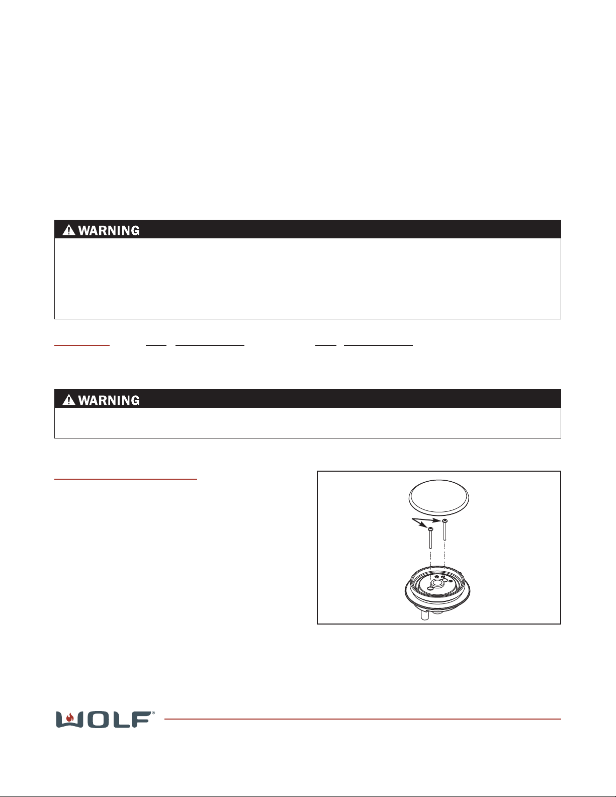
1. Remove the two T-15, 6-Lobe screws from the
15,000 Btu/hr burner. (See Figure 1)
2. Once screws are removed, gently lift up on burner
head. Using a needle nose pliers unplug
Electrode and set this aside (placing inside orifice
holder helps to keep it in correct relative position).
3. Set burner head aside.
NOTES:
• For use on models CT30G/S - LP, CT30G/P - LP, CT36G/S - LP, CT36G/P - LP
• These instructions pertain to the conversion of the above listed conventional LP Gas Wolf Cooktop to a high
altitude unit - anything between 8,600 and 10,250 feet above sea level.
• Some units may not contain all the burners combinations this package contains conversion components and
information for.
THIS CONVERSION KIT MUST BE INSTALLED BY A QUALIFIED SERVICE TECHNICIAN IN ACCORDANCE
WITH THESE INSTRUCTIONS AND ALL APPLICABLE LOCAL CODES AND REQUIREMENTS. IF THESE
INSTRUCTIONS ARE NOT FOLLOWED AS WRITTEN A FIRE, EXPLOSION OR PRODUCTION CARBON
MONOXIDE COULD OCCUR CAUSING PROPERTY DAMAGE, PERSONAL INJURY OR DEATH! THE CONVERSION IS NOT COMPLETE UNTIL THE APPLIANCE IS CHECKED FOR PROPER OPERATION AS SPECIFIED IN THESE INSTRUCTIONS.
TOOLS NEEDED: T-15 Torx Driver, 7mm Nut Driver, Torque Wrench – inch/lbs, Needle-nose Pliers
BEFORE PROCEEDING, SHUT OFF GAS SUPPLY TO APPLIANCE BEFORE DISCONNECTING ELECTRICAL POWER!
Figure 1. Burner Removal
T-15 6-Lobe Screws
Page 2
815897
Wolf Gas Cooktop-3 LP High Altitude Conversion Kit
818164 / Rev A / December, 2010Page 2 of 2
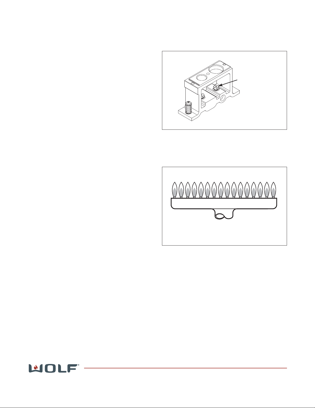
Figure 2.
4. Using the 7mm nut driver, remove the main orifice
and set aside (See Figure 2).
5. Replace the 15,000 Btu/hr main orifice, stamped
119, with orifice stamped 105 from package.
6. Re-assemble the burner head by plugging in the
electrode and inserting the burner back into the jet
holder
NOTE: Watch that the electrode wire does not
get caught between the burner and the jet holder.
Also make sure the burner is sitting down completely. You may need to pull forward slightly to
allow the electrode bracket to clear the burner
pan.
7. New screws are available in the package if needed. Tighten down the burner head screws to 24
inch-lbs.
Flame Characteristics:
The flame produced by the burner should be a quiet,
blue flame, exhibiting no lifting or blowing. The following illustration shows a desirable flame.
Figure 3 shows a desirable flame.
No modifications should need to be made to the
flame, but if the burner is not exhibiting a proper flame
and modifications need to be made, the CO level
should be monitored at all times during modification.
Ignition System:
If the unit is operating properly after conversion, the
burners should ignite within 4 seconds of the gas flowing out of the burner ports. If the flame is extinguished, the unit should also automatically re-ignite
within 4 seconds. When the burner is operating correctly, with a proper, hard flame, the unit should not be
sparking.
Leak Testing:
With all orifices converted, apply soapy water to all
joints and fittings. Turn on all burners and check thoroughly for leaks. Then turn off all the burners and
recheck for leaks.
Labels:
Once installation of all orifices is complete, and all the
appropriate tests have been satisfied, fill out all applicable information and affix the High Altitude Gas
Cooktop Rating Label as close as possible to the
existing rating plate.
Figure 3.
Main Orifice
NORMAL HARD FLAME
 Loading...