

Page 1
!
EXTERIOR VENTILATOR KITS
MODEL 801642
Page 1
WARNING
TO REDUCE THE RISK OF FIRE, ELECTRIC SHOCK, OR INJURY TO PERSONS, OBSERVE THE FOLLOWING:
1. Use this unit only in the manner intended by the manufacturer. If you have questions, contact the manufacturer or your
distributor.
2. Before servicing or cleaning unit, switch power off at service
panel and lock the service disconnecting means to prevent
power from being switched on accidentally. When the service disconnecting means cannot be locked, securely fasten
a prominent warning device, such as a tag, to the service
panel.
3. Installation work and electrical wiring must be done by a
qualified person(s) in accordance with all applicable codes
and standards, including fire-rated construction codes and
standards.
4. Sufficient air is needed for proper combustion and exhausting of gases through the flue (chimney) of fuel burning equipment to prevent backdrafting. Follow the heating equipment
manufacturer’s guidelines and safety standards such as
those published by the National Fire Protection Association
(NFPA), and the American Society for Heating, Refrigeration
and Air Conditioning Engineers (ASHRAE), and the local
code authorities.
5. When cutting or drilling into wall or ceiling, do not damage
electrical wiring and other hidden utilities.
6. Ducted fans must always be vented to the outdoors.
7. Do not use this unit with an additional speed control device.
8. To reduce the risk of fire, use only steel ductwork.
9. This unit must be grounded.
TO REDUCE THE RISK OF A COOKTOP GREASE FIRE:
1. Never leave surface units unattended at high settings.
Boilovers cause smoking and greasy spillovers that may ignite. Heat oils slowly on low or medium settings.
2. Always turn hood ON when cooking at high heat or when
cooking flaming foods.
3. Clean ventilating fans frequently. Grease should not be allowed to accumulate on fan or filter.
4. Use proper pan size. Always use cookware appropriate for
the size of the surface element.
TO REDUCE THE RISK OF INJURY TO PERSONS IN THE
EVENT OF A COOKTOP GREASE FIRE, OBSERVE THE
FOLLOWING:*
1. SMOTHER FLAMES with a close-fitting lid, cookie sheet, or
metal tray, then turn off the burner. BE CAREFUL TO PREVENT BURNS. If the flames do not go out immediately,
EVACUATE AND CALL THE FIRE DEPARTMENT.
2. NEVER PICK UP A FLAMING PAN - You may be burned.
3. DO NOT USE WATER, including wet dishcloths or towels violent steam explosion will result.
4. Use an extinguisher ONLY if:
A. You know you have a Class ABC extinguisher and you
already know how to operate it.
B. The fire is small and contained in the area where it started.
C. The fire department is being called.
D. You can fight the fire with your back to an exit.
* Based on “Kitchen Fire Safety Tips” published by NFPA.
CAUTION
1. For general ventilating use only. Do not use to exhaust hazardous or explosive materials and vapors.
2. To avoid motor bearing damage and noisy and/or unbalanced impellers, keep drywall spray, construction dust, etc.
off power unit.
3. Your ventilator motor has a thermal overload which will automatically shut off the motor if it becomes overheated. The
motor will restart when it cools down. If the motor continues to
shut off and restart, have the hood serviced.
4. Please read specification label on product for further information and requirements.
SPECIFICATIONS
MODEL VOLTS AMPS CFM DUCT SIZE
801642 120 3.0 1200 10" DIA.
PLAN THE INSTALLATION
1. Locate the ventilator so the length of the duct run and number
of elbows and transitions needed are kept to a minimum.
2. Where possible, ventilator should be located between wall
studs or roof rafters.
3. Avoid pipes, wires, or other ductwork that may be running
through the wall.
4. Be sure that there is enough space for any transitions that may
be needed between the ventilator and the connecting
ductwork.
5. For best performance, locate transitions nearest to ventilator.
Page 2
MODEL 801642
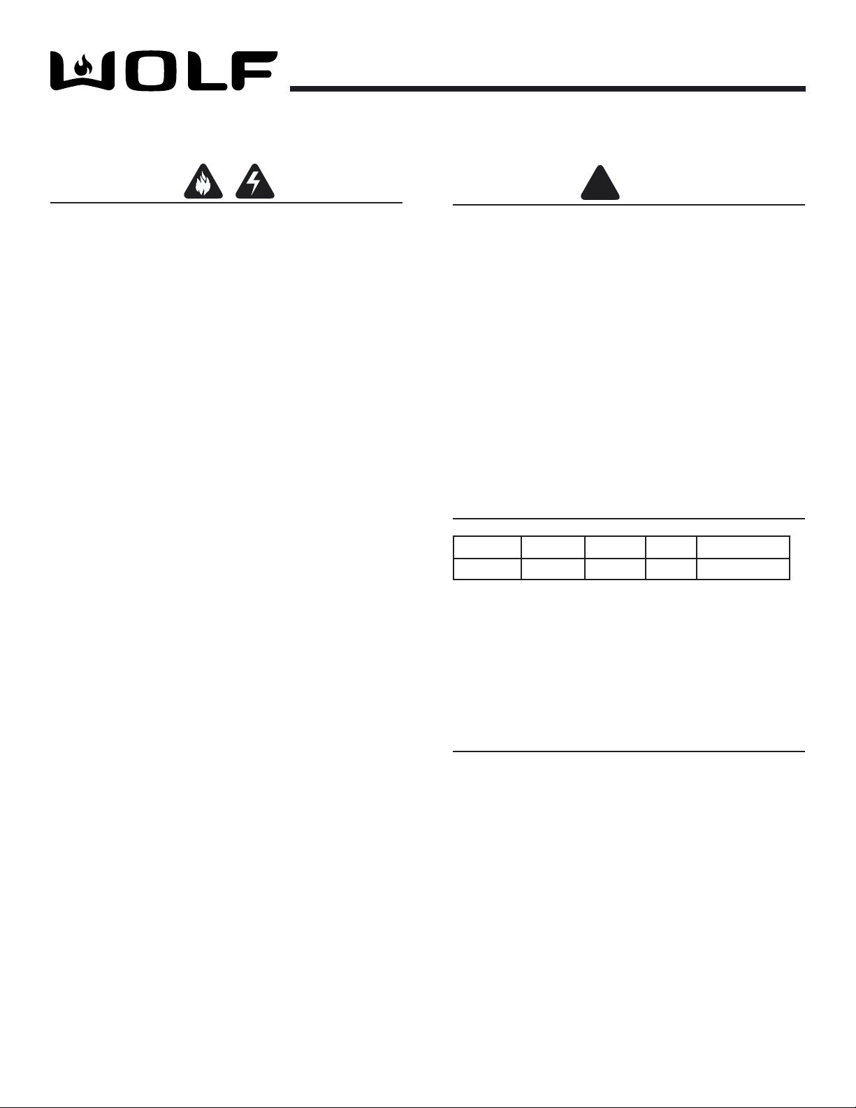
OUTSIDE - ROOF VIEW
OUTSIDE - ROOF VIEW
10 Cover
Screws
Drill 6
Mounting
Holes
Remove
roofing
nails from
top 2/3 of
shingles.
Bird Screen
Flashing
Sheet
11" dia.
hole
20½"
911/16 "
18"
1211/
16 "
1¼" dia. hole
Roof Rafter
Roof Rafter
REMOVE SHINGLES
Pilot Hole
(centered
between rafters)
ROOF MOUNT
INSTALLATION
Page 2
For use with Wolf CTWH30/CTWH36 wall mount, IH4227 island chimney hoods, DD30R/DD36R downdraft ventilators, 18” tall
island/wall hoods & 12” tall liners.
PREPARE THE ROOF
15"
1¼" dia. hole
REMOVE SHINGLES
1211/
16"
Roof Rafter
Pilot Hole
(centered
between rafters)
11" dia.
hole
1"
20½"
Roof Rafter
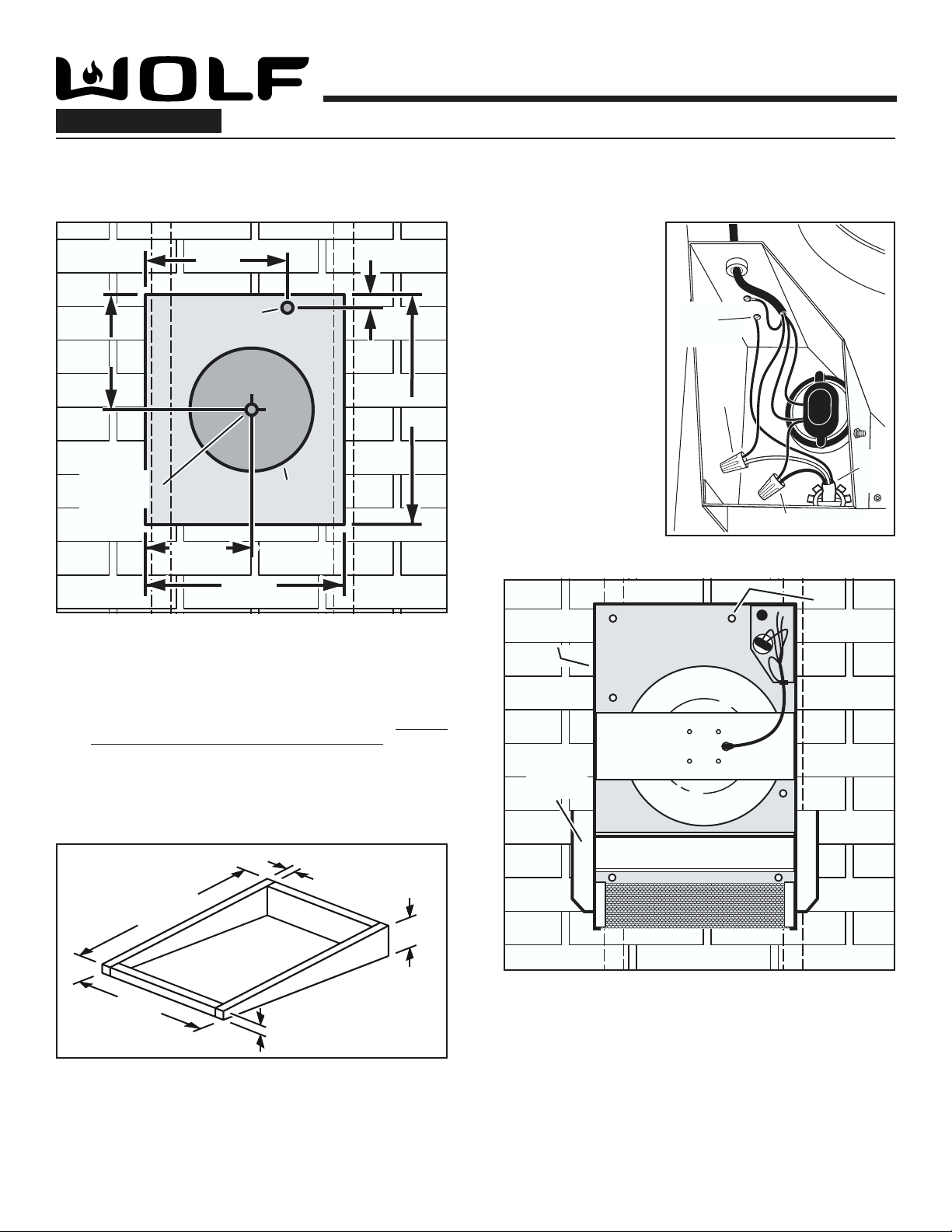
WIRE THE VENTILATOR
Remove 10
q 5
COVER SCREWS
and lift off
ventilator cover.
Feed the electric
q 6
power cable
through the 1¼"
DIAMETER HOLE
and connect cable
to ventilator with a
proper connector
for the type of
cable being used.
Connect BLACK
q 7
TO BLACK,
WHITE TO BLUE,
and GROUND TO
GROUNDING
SCREW.
GROUND
TO
GROUNDING
SCREW
WHITE
TO
BLUE
BLACK TO BLACK
120
VAC
LINE
IN
913/16"
INSTALL THE VENTILATOR
18"
From inside the attic space:
Drill a PILOT HOLE up through the roof, centered between
q 1
ROOF RAFTERS.
From outside - on the roof:
Measure and mark the 18" x 20½" rectangle. Cut and
q 2
remove only the shingles inside this rectangle.
Measure and mark the 11" DIAMETER HOLE and the
q 3
1¼" DIAMETER HOLE. Cut these holes all the way through
the roof.
10 Cover
10 Cover
Screws
Screws
Flashing
Sheet
Drill 6
Mounting
Holes
Remove
roofing
nails from
top 2/3 of
shingles.
For flat roof installations:
q 4
Build a curb that will mount the blower at a minimum pitch
of 2/12. Discharge end of the blower should be pointed
away from prevailing winds.
29½"
22"
2"
2"
7"
Damper
Bird Screen
OUTSIDE - ROOF VIEW
OUTSIDE - ROOF VIEW
Remove roofing nails from top 2/3 of shingles around
q 8
cut-out area.
Slide the ventilator's FLASHING SHEET up and under
q 9
the loosened shingles until ventilator's discharge collar
fits into 11" diameter hole.
Use the 6 screws (provided) to attach the ventilator to
q 10
the roof. DRILL 6 MOUNTING HOLES inside the
ventilator, as necessary.
Seal the screw heads, loosened shingles, and edges
q 11
of the flashing sheet, with a good grade of roofing
cement.
Check for free movement of the spring-loaded
q 12
DAMPER, and re-install the ventilator cover. Turn on
power and check operation.
Page 3
MODEL 801642
OUTSIDE - ROOF VIEW
OUTSIDE - ROOF VIEW
10 Cover
Screws
Drill 6
Mounting
Holes
Bird Screen
Flashing
Sheet
11" dia.
hole
22"
Pilot Hole
(centered between studs)
29½"
1113/16"
17"
1¼" dia. hole
REMOVE
SIDING
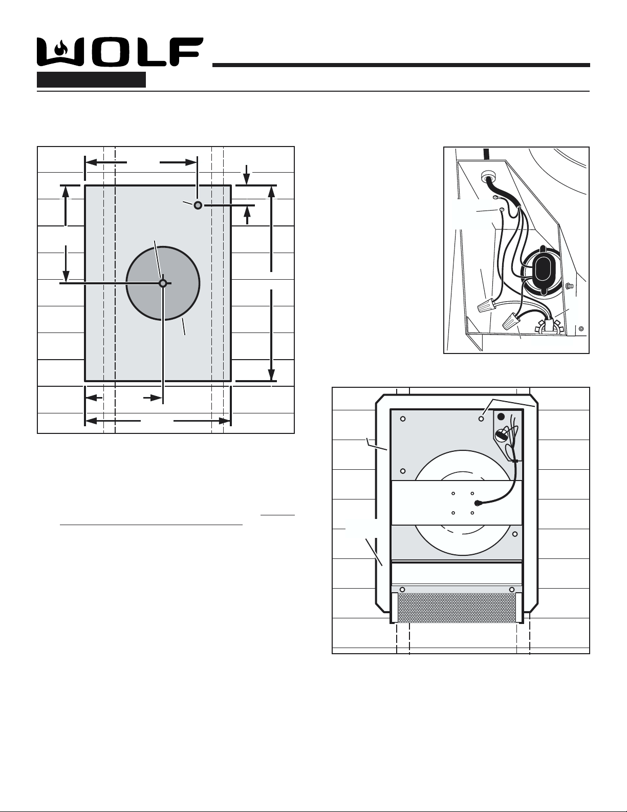
WALL MOUNT
INSTALLATION
Page 3
For use with Wolf CTWH30/CTWH36 wall mount, IH4227 island chimney hoods, DD30R/DD36R downdraft ventilators, 18” tall
island/wall hoods & 12” tall liners.
PREPARE THE WALL
17"
1¼" dia. hole
Pilot Hole
Wall Stud
REMOVE
SIDING
11" dia.
hole
1411/16"
(centered between studs)
3
Wall Stud
"
29½"
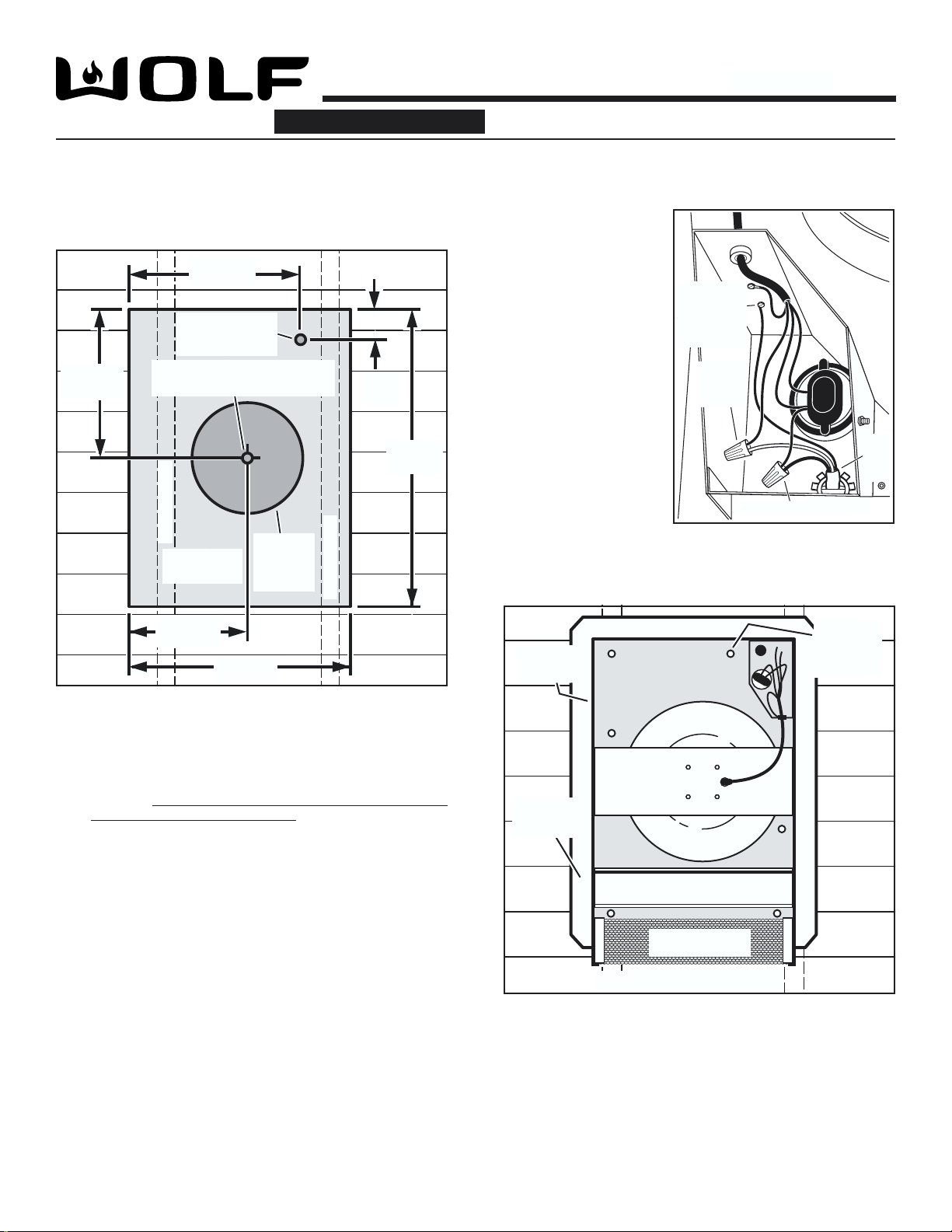
WIRE THE VENTILATOR
Remove 10
q 4
COVER SCREWS
and lift off
ventilator cover.
Feed the electric
q 5
power cable
through the 1¼"
DIAMETER HOLE
and connect cable
to ventilator with a
proper connector
for the type of
cable being used.
Connect BLACK
q 6
TO BLACK,
WHITE TO BLUE,
and GROUND TO
GROUNDING
SCREW.
GROUND
TO
GROUNDING
SCREW
WHITE
TO
BLUE
BLACK TO BLACK
120
VAC
LINE
IN
INSTALL THE VENTILATOR
From inside the wall:
Drill a PILOT HOLE through the wall, centered between
q 1
WALL STUDS.
From outside - on the wall:
Measure and mark the 22" x 29½" rectangle. Cut and
q 2
remove only the siding inside this rectangle.
Measure and mark the 11" DIAMETER HOLE and the
q 3
1¼" DIAMETER HOLE. Cut these holes all the way through
the wall.
1113/16"
22"
10 Cover
10 Cover
Screws
Screws
Mounting
Flashing
Sheet
Damper
Bird Screen
OUTSIDE - ROOF VIEW
OUTSIDE - WALL VIEW
Place ventilator on wall so that ventilator's discharge collar
q 7
fits into 11" diameter hole.
Use the 6 screws (provided) to attach the ventilator to the
q 8
wall. DRILL 6 MOUNTING HOLES inside the ventilator , as
necessary.
Seal the screw heads and edges of the flashing sheet with
q 9
a good grade of roofing cement.
Check for free movement of the spring-loaded DAMPER
q 10
and re-install ventilator cover. Turn on power and check
operation.
Drill 6
Holes
Page 4

MODEL 801642
Page 4
ATTACH POWER CORD TO HOOD
Some hoods require the use of a separate power cord and strain relief bushing (included), for proper
wiring of exterior blowers. Please refer to the hood manual for proper installation instructions.
Page 5

Page 6

MODEL 801642
MODÈLE
ENSEMBLES DE VENTILA TEURS EXTÉRIEURS
Page 5
AVERTISSEMENT
OBSERVEZ LES DIRECTIVES CI-DESSOUS DE MANIÈRE À
RÉDUIRE LES RISQUES D’INCENDIE, DE CHOC ÉLECTRIQUE OU
DE BLESSURES CORPORELLES.
1. N’utilisez cet appareil que de la manière prévue par le fabricant. Si
vous avez des questions, contactez le fabricant ou le distributeur.
2. Avant de procéder à la réparation ou à l’entretien de l’appareil, coupez
l’alimentation du panneau d’entrée d’électricité et verrouillez le dispositif
de sectionnement de manière à empêcher que le courant ne soit
accidentellement rétabli. S’il est impossible de verrouiller le dispositif
de sectionnement, fixez solidement un système de protection bien en
vue, par exemple une étiquette, au panneau d’entrée d’électricité.
3. La pose de l’appareil et les travaux d’électricité doivent être effectués
par des personnes qualifiées en respectant la réglementation en
vigueur, notamment les codes et normes de la construction ayant trait
à la résistance au feu.
4. Pour éviter les refoulements, l’apport d’air doit être suffisant de manière
à brûler et à évacuer, par le conduit de fumée (cheminée), les gaz
produits par les appareils à combustibles. Respectez les directives
du fabricant de l’appareil de chauffage et les normes de sécurité,
notamment celles publiées par la National Fire Protection Association
(NFP A), la American Society for Heating, les Refrigeration and Air
Conditioning Engineers (ASHRAE) et les codes des autorités locales.
5. Veillez à ne pas endommager le câblage électrique ou d’autres
équipements non apparents lors de la déco upe ou du perçage du
mur ou du plafond.
6. Les ventilateurs canalisés doivent toujours être ventilés à l’air libre.
7. N’utilisez pas de commande de régime supplémentaire pour cet
appareil.
8. Pour réduire les risques d’incendie, utilisez seulement des conduits
en acier.
9. Cet appareil doit être mis à la terre.
POUR RÉDUIRE LES RISQUES D’INCENDIE CAUSÉS PAR DE LA
GRAISSE SUR LA SURF ACE DE CUISSON :
1. Ne laissez jamais les éléments de surface allumés à haute
température. Les débordements peuvent causer de la fumée et des
écoulements de graisse inflammables. L’huile doit être chauffée
graduellement à basse ou à moyenne température.
2. Mettez toujours la hotte en fonction (ON) lors de la cuisson à haute
température ou lors de la cuisson d’aliments à flamber.
3. Nettoyez fréquemment les ventilateurs. Ne laissez pas la graisse
s’accumuler sur le ventilateur ou le filtre.
4. Utilisez des casseroles de dimension appropriée. Utilisez toujours
une batterie de cuisine adaptée à la dimension des éléments de
surface.
OBSERVEZ LES CONSIGNES SUIVANTES DE MANIÈRE À
RÉDUIRE LES RISQUES DE BLESSURES CORPORELLES EN CAS
D’INCENDIE CAUSÉ PAR DE LA GRAISSE SUR LA SURF ACE DE
CUISSON.
1. ÉTOUFFEZ LES FLAMMES à l’aide d’un couvercle étanche, d’ une
tôle à biscuits ou d’un plateau en métal puis éteignez le brûleur.
FAITES A TTENTION DE NE P AS VOUS BRÛLER. Si les flammes
ne s’éteignent pas immédiatement, QUITTEZ LES LIEUX ET
APPELEZ LE SERVICE DES INCENDIES.
2. NE SOULEVEZ JAMAIS UNE CASSEROLE EN FLAMMES — vous
pourriez vous brûler.
3. N’UTILISEZ P AS D’EAU, ni de linges ou de serviettes mouillés - une
violente explosion de vapeur pourrait survenir.
4. Utilisez un extincteur SEULEMENT si :
A. Vous savez qu’il est de classe ABC et vous connaissez déjà son
mode de fonctionnement.
B. L’incendie n’est pas très important et ne se propage pas.
C. Vous avez déjà téléphoné au service des incendies.
D. Vous pouvez combattre l’incendie en faisant dos à une sortie.
* Conseils tirés de la publication de la NFP A « Kitchen Fire Safety Tips ».
ATTENTION
1. Cet appareil ne doit servir qu’à la ventilation générale. Il ne doit pas
être utilisé pour éliminer des matières ni des vapeurs dangereuses ou
explosives.
2. Pour éviter d’endommager les roulements de moteur, de déséquilibrer
les pales ou de les rendre bruyantes, débarrassez l’appareil de la
poussière de plâtre, de construction, etc.
3. Le moteur du ventilateur est muni d’un dispositif de protection de
surcharge électrique qui coupe automatiquement le moteur en cas de
surchauffe. Il se remet en marche lorsqu’il a refroidi. Faites réparer la
hotte si le moteur continue à fonctionner par intermittence.
4. Veuillez lire l’étiquette de spécifications du produit pour obtenir plus de
renseignements, notamment sur les normes.
!
CARACTÉRISTIQUES
MODÈLE VOLTS AMPS PCM DIMENSION DU CONDUIT
801642 120 3.0 1200 DIAM. DE 254 mm (10 po)
PLANIFICATION DE LA POSE
1. L’emplacement de pose du ventilateur doit être choisi de manière à
réduire le plus possible l’utilisation de conduits de transition et de
coudes.
2. Si cela est envisageable, placez le ventilateur entre les poteaux
muraux ou les chevrons du toit.
3. Évitez les tuyaux, les fils ou autres conduits qui peuvent passer dans
les murs.
4. Assurez-vous qu’il y a suffisamment d’espace pour placer les
conduits de transition requis entre le ventilateur et les conduits de
raccordement.
5. Pour de meilleurs résultats, placez les conduits de transition le plus
près possible du ventilateur.
Page 7

MODEL 801642
10 Cover
Screws
Drill 6
Mounting
Holes
Remove
roofing
nails from
top 2/3 of
shingles.
Bird Screen
Flashing
Sheet
11" dia.
hole
20½"
911/16"
18"
1211/16"
1¼" dia. hole
Roof Rafter
Roof Rafter
REMOVE SHINGLES
Pilot Hole
(centered
between rafters)
BLACK TO BLACK
WHITE
TO
BLUE
120
VAC
LINE
IN
GROUND
TO
GROUNDING
SCREW
MODÈLE
INSTALLATION
MONTÉS SUR LE TOIT
Page 6
À utiliser avec les hottes murales Wolf CTWH30/CTWH36, hottes pour cheminée d'îlot IH4227, hottes à tirage descendent
DD30R/DD36R, hottes d'îlot/nurales de 45,7 cm (18") de
hauteur et gaines de 30,5 CM (12") de hauteur.
PRÉPARATION DU TOIT
381 mm
15"
(15 po)
Orifice d’un diamètre de
1¼" dia. hole
32 mm (1¼ po)
ENLEVEZ LES BARDEAUX
322 mm
1211/16"
(12-11/16 po)
Avant-trou
Pilot Hole
(centré entre les
chevrons)
(centered
between rafters)
REMOVE SHINGLES
Chevron
Roof Rafter
Orifice d’un
11" dia.
diamètre de
hole
279 mm
(11 po)
249 mm
913/16"
(9-13/16 po)
457 mm
18"
(18 po)
25
1"
mm
(1 po)
521 mm
20½"
(20½ po)
Chevron
Roof Rafter
CÂBLAGE DU VENTILATEUR
Retirez les 10 VIS
q 5
DU COUVERCLE et
soulevez le
couvercle du
ventilateur.
Faites passer le
q 6
câble d’alimentation
électrique par
L’ORIFICE D’UN
DIAMÈTRE DE 32
MM (1 ¼ PO) et
branchez le câble au
ventilateur à l’aide
d’un connecteur
convenant au type
de câble utilisé.
Branchez les FILS
q 7
NOIRS ENSEMBLE,
LE FIL BLANC
AVEC LE FIL BLEU,
et le FIL DE TERRE
AVEC LA VIS DE
MISE À LA TERRE.
FIL DE TERRE
AVEC VIS DE
MISE À LA
TERRE
BLANC
AVEC
BLEU
NOIR AVEC NOIR
POSE DU VENTILATEUR
10 Cover
10 Cover
10 vis de
Screws
Screws
couvercle
LIGNE
120
VCA
Drill 6
Percez 6
trous de
Mounting
fixation
Holes
De l’intérieur du grenier :
Percez un AVANT-TROU à travers le toit, centré entre les
q 1
CHEVRONS.
De l’extérieur –sur le toit :
Mesurez et tracez un rectangle de 457 mm x 521 mm (18 po x
q 2
20 ½ po).
trouvent à l’intérieur de ce rectangle.
Mesurez et tracez un ORIFICE D’UN DIAMÈTRE DE 279 MM
q 3
(11 PO) et un ORIFICE D’UN DIAMÈTRE DE 32 MM (1 ¼ PO).
Découpez ces orifices de part en part du toit.
Pose sur un toit plat :
Construisez un cadre porteur pour supporter le ventilateur en
q 4
vous assurant que la pente minimale est de 2/12. L’extrémité du
conduit d’évacuation du ventilateur ne doit pas être orientée dans
la direction dominante du vent.
Coupez et retirez seulement les bardeaux qui se
29½"
749 mm (29 ½ po)
559 mm
25"
(22 po)
51 mm
(2 po)
2"
51 mm
2"
(2 po)
178 mm
(7 po)
7"
nails from
clous de toiture
Flashing
Plaque de
protection
Sheet
Registre
Damper
Grillage aviaire
Bird Screen
EXTÉRIEUR – VUE DU TOIT
Déclouez partiellement les bardeaux autour de la zone de découpe
q 8
en laissant les clous de toiture enfoncés au tiers.
Faites glisser la PLAQUE DE PROTECTION par-dessus ou en
q 9
dessous des bardeaux partiellement décloués jusqu’à ce que le
collier du conduit d’évacuation du ventilateur puisse pénétrer
dans l’orifice d’un diamètre de 279 mm (11 po).
Utilisez les 6 vis fournies pour fixer le ventilateur au toit. Au
q 10
besoin, PERCEZ 6 TROUS DE FIXATION à l’intérieur du
ventilateur.
Imperméabilisez les têtes des vis, les bardeaux partiellement
q 11
décloués et les rebords de la plaque de protection à l’aide de
colle pour toiture de bonne qualité.
Assurez-vous que le REGISTRE à ressort bouge librement
q 12
puis réinstallez le couvercle du ventilateur. Mettez l’appareil
sous tension et vérifiez son fonctionnement.
Déclouez
partiellement
Remove
les bardeaux
roofing
du toit en
laissant les
top 2/3 of
enfoncés au
shingles.
tiers.
Page 8
MODEL 801642
10 Cover
Screws
Drill 6
Mounting
Holes
Bird Screen
Flashing
Sheet
11" dia.
hole
22"
Pilot Hole
(centered between studs)
29½"
1113/16"
17"
1¼" dia. hole
REMOVE
SIDING
MODÈLE
INSTALLATION
MONTÉS SUR LE MUR
Page 7
À utiliser avec les hottes murales Wolf CTWH30/CTWH36, hottes pour cheminée d'îlot IH4227, hottes à tirage descendent
DD30R/DD36R, hottes d'îlot/nurales de 45,7 cm (18") de
hauteur et gaines de 30,5 CM (12") de hauteur.
PRÉPARATION DU MUR
432 mm
17"
(17 po)
Orifice d’un
1¼" dia. hole
diamètre de
32 mm (1¼ po)
357 mm
(14-11/16 po)
1411/16"
Avant-trou (centré entre les
(centered between studs)
Poteau mural
ENLEVEZ LE
PAREMENT
Pilot Hole
poteaux muraux)
Wall Stud
REMOVE
SIDING
Orifice d’un
11" dia.
diamètre de
hole
279 mm
(11 po)
76 mm
Wall Stud
Poteau mural
3
"
(3 po)
749 mm
29½"
(29½ po)
CÂBLAGE DU VENTILATEUR
Retirez les 10 VIS
q 4
DU COUVERCLE et
soulevez le
couvercle du
ventilateur.
Faites passer le
q 5
câble d’alimentation
électrique par
L’ORIFICE D’UN
DIAMÈTRE DE 32
MM (1 ¼ PO) et
branchez le câble au
ventilateur à l’aide
d’un connecteur
convenant au type
de câble utilisé.
Branchez les FILS
q 6
NOIRS ENSEMBLE,
LE FIL BLANC
AVEC LE FIL BLEU,
et le FIL DE TERRE
AVEC LA VIS DE
MISE À LA TERRE.
FIL DE TERRE
GROUND
AVEC VIS DE
TO
GROUNDING
MISE À LA
SCREW
TERRE
WHITE
BLANC
TO
AVEC
BLUE
BLEU
BLACK TO BLACK
NOIR AVEC NOIR
POSE DU VENTILATEUR
120
LIGNE
VAC
120
LINE
VCA
IN
De l’intérieur du mur :
Percez un AVANT-TROU à travers le mur, centré entre les
q 1
POTEAUX MURAUX.
De l’extérieur –sur le mur :
Mesurez et tracez un rectangle de 559 mm x 749 mm (22 po x
q 2
29 ½ po).
trouvent à l’intérieur de ce rectangle.
Mesurez et tracez un ORIFICE D’UN DIAMÈTRE DE 279 MM
q 3
(11 PO) et un ORIFICE D’UN DIAMÈTRE DE 32 MM (1 ¼ PO).
Découpez ces orifices de part en part du mur.
300 mm
1113/16"
(11-13/16 po)
559 mm
22"
(22 po)
Coupez et retirez seulement les bardeaux qui se
10 Cover
10 Cover
10 vis de
couvercle
Screws
Screws
Flashing
Plaque de
Sheet
protection
Registre
Damper
Bird Screen
Grillage aviaire
EXTÉRIEUR –VUE DU MUR
Placez le ventilateur sur le mur de manière à ce que le collier du
q 7
conduit d’évacuation du ventilateur puisse pénétrer dans l’orifice
d’un diamètre de 279 mm (11 po).
Utilisez les 6 vis fournies pour fixer le ventilateur au mur. Au
q 8
besoin, PERCEZ 6 TROUS DE FIXATION à l’intérieur du
ventilateur.
Imperméabilisez les têtes des vis et les rebords de la plaque de
q 9
protection à l’aide de colle pour toiture de bonne qualité.
Assurez -vous que le REGISTRE à ressort bouge librement
q 10
puis réinstallez le couvercle du ventilateur. Mettez l’appareil
sous tension et vérifiez son fonctionnement.
-
-
Mounting
Drill 6
Percez 6
trous de
fixation
Holes
Page 9

MODEL 801642
MODÈLE
Page 8
ATTACHEZ LE CORDE DE COURANT AU HOTTE
Quelques hottes exigent l’utilisation d’un corde de courant électrique et douille de passe-fils séparé
(inclus), pour le câblage approprié des ventilateurs extérieurs. Veuillez se référer au manuel de hotte
pour des instructions d’installation appropriées.
99043277A
 Loading...