

Page 1
OMUS® user manual
Revision 8, March 2017
OMUS®
Electronic hybrid switch for resistive loads.
User manual
Revision 8, March 2017
Page 2

OMUS® user manual
Revision 8, March 2017
Contents
1 Design variants ....................................................................................................................................................... 38
2 OMUS® Overview .................................................................................................................................................... 39
2.1 Application ............................................................................................................................................................ 40
2.2 Incorporation of OMUS® into process control ....................................................................................................... 41
2.3 Galvanic isolation & short-circuit protection ........................................................................................................ 41
2.4 Line protection ...................................................................................................................................................... 43
2.5 Switching processes in the hybrid switch ............................................................................................................. 43
2.6 Adhering to limit values in switching processes ................................................................................................... 43
2.7 Adjustability of the power output ......................................................................................................................... 46
2.8 Suitability of the application ................................................................................................................................. 47
3 Safety instructions / Installation instructions .......................................................................................................... 48
4 Product table .......................................................................................................................................................... 49
5 Commissioning ....................................................................................................................................................... 50
5.1 Connections .......................................................................................................................................................... 50
5.2 Installing and connecting the main circuits ........................................................................................................... 51
5.3 Meaning of the LED indicators .............................................................................................................................. 52
5.4 Disassembly and replacing devices ....................................................................................................................... 52
5.5 Replacing a fuse .................................................................................................................................................... 53
5.6 Checklist ................................................................................................................................................................ 54
6 User interface ......................................................................................................................................................... 55
6.1 Front view ............................................................................................................................................................. 55
6.2 Overview of display functions ............................................................................................................................... 56
6.3 Eplan symbol ......................................................................................................................................................... 57
6.4 Switching variants ................................................................................................................................................. 58
7 Configuration of OMUS® ......................................................................................................................................... 59
7.1 Menu structure ..................................................................................................................................................... 60
7.2 Three-phase settings ............................................................................................................................................. 61
7.3 Single-phase settings ............................................................................................................................................ 62
7.4 Restoring to factory settings ................................................................................................................................. 63
7.5 Standby ................................................................................................................................................................. 63
8 Function description ............................................................................................................................................... 64
8.1 Auto(matic) mode ................................................................................................................................................. 64
8.2 Settings menu ....................................................................................................................................................... 64
8.3 Manual mode ........................................................................................................................................................ 64
8.4 Warning ................................................................................................................................................................ 65
8.5 Error ...................................................................................................................................................................... 66
8.6 Acknowledgement of messages ............................................................................................................................ 67
8.7 Interruption .......................................................................................................................................................... 67
9 Technical data ........................................................................................................................................................ 68
Page 3
OMUS® user manual
Revision 8, March 2017
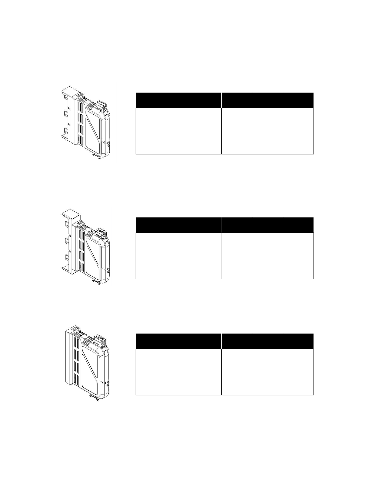
1 Design variants
OMUS®30Compact
Type
Pack Size
Weight
kg/100
Part No.
OMUS®30Compact, IEC
1
45.2
36 152
OMUS®30Compact, UL and IEC
1
45.2
36 157
OMUS®60Classic
Type
Pack Size
Weight
kg/100
Part No.
OMUS®60Classic, IEC
1
45.8
36 153
OMUS®60Classic, UL and IEC
1
45.8
36 158
OMUS®CrossBoard
Type
Pack Size
Weight
kg/100
Part No.
OMUS®Crossboard, IEC
1
35.7
36 154
OMUS®Crossboard, UL and IEC
1
35.7
36 159
Page 4
OMUS® user manual
Revision 8, March 2017
2 OMUS® Overview
OMUS®
Electronic hybrid switch for resistive loads.
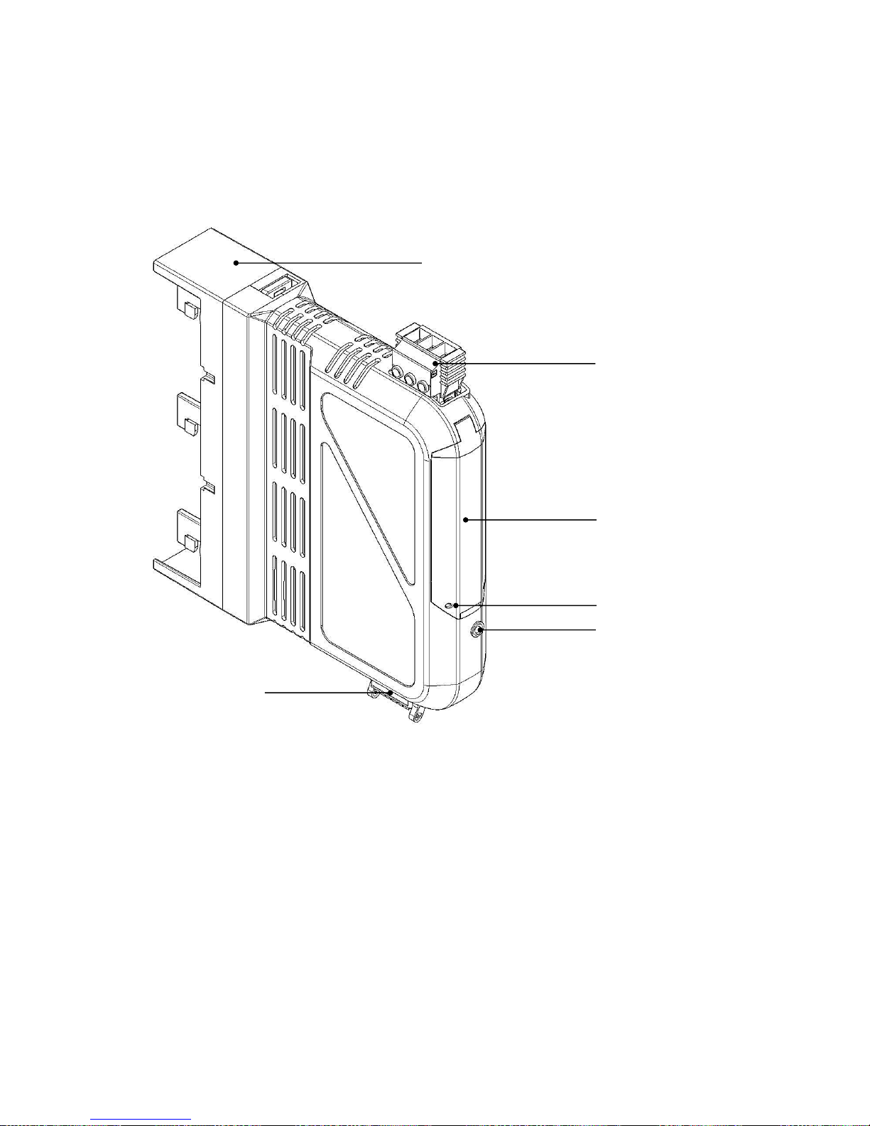
The OMUS® electronic hybrid switch is a compact switching device with a width of 36 mm. The
hybrid switch is composed of a combination of relay contacts and power semi-conductors,
integrated short-circuit protection as well as electronic current and temperature monitoring for
operational switching of resistive loads (IEC up to 25 A / 400V AC; UL up to 20A / 480V AC).
The universal CrossLink-interface at the connection side enables fast electrical and
mechanical connection with various busbar systems.
Busbar adapter
(*version 30Compact)
Load plug
Esc / Reset button
Control plug
Hinged cover
Lead sealing
Page 5

OMUS® user manual
Revision 8, March 2017
2.1 Application
The OMUS® hybrid switch has been developed for areas of application in which contactors,
overload relays, solid state relays and mechanical switches have previously been used.
This device was designed for the frequent switching of:
• single-pole resistive loads (phase-neutral) and
• three-pole resistive loads
This is a product for environment A (industry) regarding EMC. In environment B (household)
this device may cause undesirable interference; in this case the user has to find appropriate
counteraction to reduce electromagnetic interference. No powerful electrostatic charges may
be transferred to the OMUS® from the load side. An external switching element is required for
galvanic isolation. This could be a contactor or circuit breaker, for example. In a nonoperational status, the OMUS® error relay will issue a signal. In order to interrupt an
unintentional continuous current flow in case of an error, an external switchgear must ensure
the interruption of the load circuit. The short-circuit protection is implemented via integrated
fuses.
The combination of the functions
• Hybrid switch
• Feed
• Fuse
• Monitoring
enables a maximum space advantage in comparison to a group composition of three discrete
devices with comparable properties.
Page 6
OMUS® user manual
Revision 8, March 2017
2.2 Incorporation of OMUS® into process control
OMUS® can be actuated with the help of a programmable logic controller (PLC). The precise
specification for the input signals of OMUS® is described in detail, in chapter 9 Technical data,
as well as in 2.5 Switching processes in the hybrid switch. The defined limit values such as a
maximum switching frequency of 1Hz and minimum on and off duration of 100ms must be
strictly adhered to in order to guarantee proper operation.
OMUS® possesses numerous self-diagnostic and safety monitoring mechanisms. Warnings
and errors are routed to the analysis unit via the signal relays.
The incorporation and active processing of the warning or error messages into the
corresponding control of the system is necessary in order to achieve the maximum
system dependability.
If the limit values are exceeded, e.g. the minimum switch on time, OMUS® has a softwarebased self-diagnostic system, and will ignore unreliable control commands. The incorrect
actuation will not be issued by a signal.
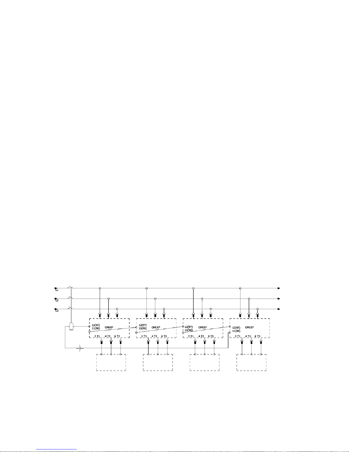
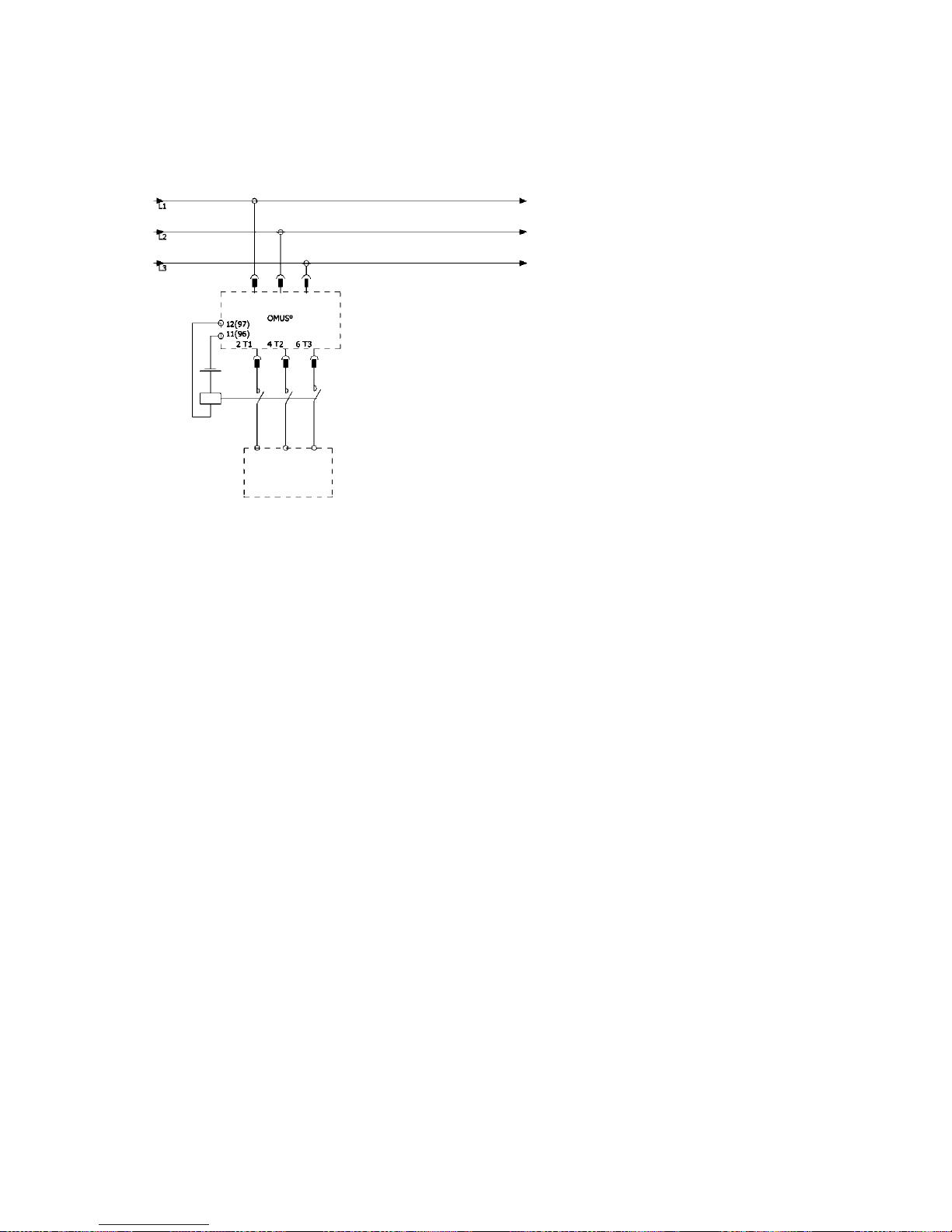
2.3 Galvanic isolation & short-circuit protection
The device does not have an internal galvanic isolation. In the event of an error, OMUS®
switches off as normal without being fully galvanically isolated. An external switching
element is required for galvanic isolation. The galvanic isolation can be realized on the part
of the feed.
Galvanic isolation on the part of the feed:
load
load
load
load
Page 7
OMUS® user manual
Revision 8, March 2017
The galvanic isolation can also be realized between OMUS® and corresponding load.
Galvanic isolation on the part of the load:
Common devices for the implementation of a galvanic isolation are contactors or circuit
breakers. In a non-operational status, the OMUS® error relay will issue a signal. In order to
interrupt an unintentional continuous current flow in case of an error, an external switchgear
must ensure the interruption of the load circuit.
The short-circuit protection is implemented via integrated fuses. An upstream short-circuit
protection module is only required from an uninfluenced short-circuit current ICP above 30kA.
For the UL design (with internal fuse Class CC 30A according to UL), an SCCR value of 30kA
was verified. The electronic hybrid switch OMUS® complies with coordination type 1.
load
Page 8

OMUS® user manual
2.4 Line protection
The line protection of the connected line is realized by setting the correct current limit (16A,
20A or 25A). In order to ensure line protection with OMUS® depending on the configured
current, at least the following wire cross-sections at the load plug have to be adhered to. The
following values comply with the single installation of OMUS®. The specified wire crosssections are additionally depending on the deratings for side-by-side installation (see chapter
9 Technical data) and if necessary installation type!
Connected
wire crosssection
Permitted
adjustable current
limits
Permitted load current
(load plug with screw
terminals
Art.-Nr. 36918)
**Permitted load current
(load plug with spring
terminals
Art.-Nr. 36916)
2,5mm²
16A, 20A
20A
16A
4mm²
16A, 20A, 25A
25A
20A
*6mm²
16A, 20A, 25A
25A
20A
*higher wire cross-section enables better heat dissipation
**spare component
If a wire cross-section below 2,5mm² is used, the line protection has to be realized either by
using smaller fuses within OMUS® or adapting the pre-fuse.
2.5 Switching processes in the hybrid switch
OMUS® combines the advantages of power semi-conductor and relay technology. The
interplay of both technologies is referred as hybrid switch. When OMUS switches on, the semiconductor carries the current so that the relay can be switched on with low wear. The
continuous current then flows through the relay, which generates significantly lower power loss
in comparison to the semi-conductor. When OMUS switches off, the semi-conductor once
again carries the current in the hybrid switch in order to open the relay contact with minimal
current arcing. In comparison to a purely relay solution, this functionality allows for a
significantly longer lifetime. Compared to a pure semi-conductor solution, the hybrid switch
operates with much greater efficiency. The high degree of efficiency translates to lower power
loss in the device.
2.6 Adhering to limit values in switching processes
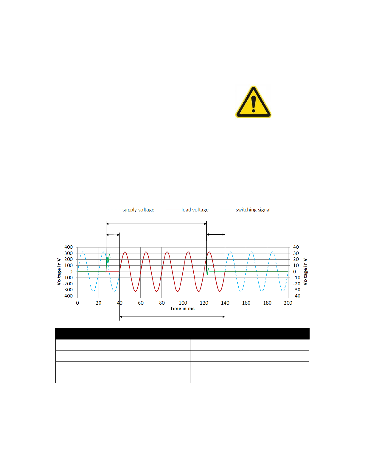
The electronics switch the load on and off at the zero crossing of the load voltage. The switch
on and off commands are carried out after a delay (max. 80ms). The minimum duration of the
switch on impulse has to be 100ms. The maximum switching frequency may not exceed 1Hz.
The minimum load current is 2A. The proper functionality of the device cannot be guaranteed
if the limit parameters are not adhered to. The electronics continuously monitor the
correct
Revision 8, March 2017
Page 9
OMUS® user manual
Revision 8, March 2017
performance of the control commands and the power consumption in all phases. Switching
processes must be conducted in line with the following rules in order to achieve a high switch
rate, long lifetime and low power loss:
• Maximum switching frequency f 1 Hz
• Minimum switch on duration t
ON
100ms
• Minimum switch off duration t
OFF
100ms
• Minimum load current I
nc min
2A
• Usage only with connected functional ground PE
(Input 2 control plug)
Note: Please complete commissioning in conjunction with working through the checklist in
subsection 5.6!
Example: Switch on and off process with minimum switching duration of 100ms:
Designation
Limit value
In example
t
switch on delay
max. 80ms
approx. 13ms
t
switch off delay
max. 80ms
approx. 17ms
t
switching signal
(duration of the switch on impulse)
min. 100ms
approx. 100ms
tON: (Switch on duration of load)
min. 100ms
approx. 100ms
Power output 3-phase at 25A load current:
• 20W power loss in continuous operation (all relays permanently on, t
Relay ON
>> 1s)
• temporary 3-fold power loss during switch on or switch off (t
Triac ON
)
t
switch on delay
t
Switching signal
t
switch off delay
t
ON
Page 10
OMUS® user manual
Revision 8, March 2017
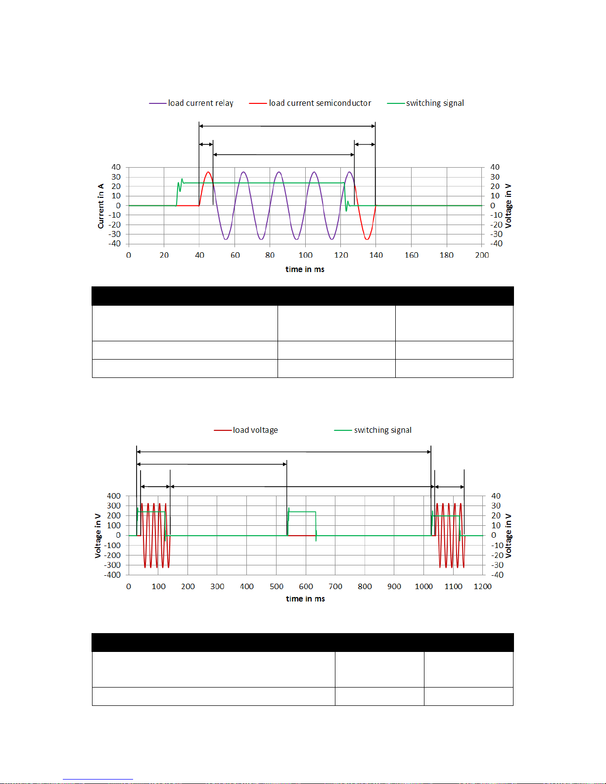
Exemplary switch on and off process with hybrid switches in detail (current flow)
Designation
Limit value
In example
t
Triac ON
(Switch on duration of Triac)
max. 20ms
approx. 8ms switch on
approx. 12ms switch off
t
Relay ON
(Switch on duration of relay)
min. 80ms
approx. 80ms
tON (Switch on duration of load)
min. 100ms
approx. 100ms
Example: Switching cycle with max. switching frequency 1Hz and min. switch on duration 100ms
Incorrect actuation (in this case: 2Hz) is ignored!
Designation
Limit value
In example
t
Period min
(Minimal period duration between
impulses)
min. 1000ms
approx. 1000ms
t
OFF
(Switch on duration of load)
min. 100ms
approx. 900ms
t
Triac ON
t
Triac ON
t
Relay ON
t
ON
tON
tON
2Hz actuation
t
Period min
t
OFF
Page 11

OMUS® user manual
Revision 8, March 2017
2.7 Adjustability of the power output
The adjustability of the power output of OMUS® occurs depending on the actuation. In
continuous operation, the consumer is continuously actuated. The output can be switched in
a timed manner to reduce the power output. The duty cycle D is characterized by the
relationship between duration of the actuation impulse and period duration of the timing:
The actuation limit parameters must be adhered to for the timing of the output. The prescribed
minimum switching duration for the load of 100 ms results in a duty cycle of 10% for the
maximum switching frequency of 1 Hz.
The max. duty cycle in timed operation at a maximum switching frequency of 1 Hz is 90%:
The max. control accuracy is determined by supply frequency and switching frequency. At
50Hz-supply frequency and 1Hz-switching frequency the max. control accuracy Acc is:
The limits of the duty cycle are depending on determined min. switch on and off times (100ms)
and the variable switching frequency. At 1Hz-switching frequency the lower limit is 10%, the
upper limit is 90%. In order to achieve a finer duty cycle, the switching frequency must be
reduced. Example for 1% duty cycle:
Switching frequency to 0.1 Hz (10s period duration)
Example for 99% duty cycle: Switching frequency to 0.1 Hz (10s period duration)
The duty cycle at a switching frequency of 0.1 Hz is adjustable between 1% and 99% in 0.2%
steps.
Duty cycle
Switching frequency
t
ON tOFF
Control accuracy
1%
0,1Hz
100ms
9900ms
0,2%
10%
1Hz
100ms
900ms
2%
54%
1Hz
540ms
460ms
2%
90%
1Hz
900ms
100ms
2%
99%
0,1Hz
9900ms
100ms
0,2%
Page 12

OMUS® user manual
Revision 8, March 2017
2.8 Suitability of the application
The basis for the use of OMUS® in the planned application is operation within the following
limit parameters.
Electrical parameters OMUS®
Specification
Type of load
resistive loads
Max. load current I
nc max
25A (IEC)
20A (UL)
Min. load current I
nc min
2A (IEC)
2A (UL)
Max. operating voltage Ue
400V AC (IEC)
480V AC (UL)
Max. switching frequency f
1Hz
Min. switch on duration t
ON
100ms
Min. switch off duration t
OFF
100ms
Max. switch on delay
80ms
Max. switch off delay
80ms
Actuation parameters (e.g. PLC)
Specification
Max. actuation impulse switching frequency f
Impulse
1Hz
Min. duration of actuation impulse t
Switch on signal
100ms
Min. timeout duration t
Switch off signal
100ms
Parameter periphery
Specification
Evaluating the warning message
Detection and rectification of the
warning’s cause
Evaluating the error message
Using the error message contacts to
switch off the load
Switch off the load during an error
galvanic isolation via external
switchgear
The limit values of Electrical parameters OMUS
®
must be adhered to by the Actuation
Parameters in order to guarantee orderly operation. The parameters listed only constitute the
basis for possible use. Additional parameters must be observed for a successful application
(see chapter 9 Technical Data and 2.5 Switching processes in the hybrid switch).
Page 13

OMUS® user manual
Revision 8, March 2017
3 Safety instructions / Installation instructions
Obey all national safety, accident prevention and industrial safety regulations when carrying
out work on the device. Failure to obey safety instructions may result in a good deal of property
damage, severe health damage or even danger to life and limb. The device may only be
commissioned, installed, modified and retrofitted by a trained electrician. Disconnect the
(busbar) system from the power supply before starting work on the device or the loads.
If the semi-conductor elements break down or the relays are stuck, the
electronics alone cannot turn off the load. In an irregular state, the error
relay issues a signal. The layout of the semi-conductor elements means
that there is no complete electrical isolation of the load from the main
supply. In order to interrupt an unintentional continuous current flow in
case of an error, an external switchgear must ensure the interruption of
the load circuit.
The safety regulations set out in DGUV V3 (BGV A3) are to be used for work. During operation,
parts of the electrical switchgear can carry dangerous voltage! Safety covers must not be
removed from electrical switchgear during operation. Keep the user manual in a safe place!
The device must not be installed in potentially explosive atmospheres. Obey the safety
regulations which apply to the installation and operation of related equipment. The device must
not be exposed to mechanical or thermal stresses which exceed the limits described in the
user manual. If necessary, the device may be installed in an appropriate housing with a suitable
protection type (for example IP54) to IEC 60529 / EN 60529 to protect it from mechanical or
electrical damage. If the device is used in dusty environment, it must be installed in a suitable
housing (at least IP64) to EN 61241. Access to the circuits inside the device is not permitted
during operation. The equipment cannot be repaired by the user and must be replaced by an
equivalent device. Repair work may only be carried out by the device manufacturer. The device
conducts function self-diagnostics continuously during operation. A warning or error may be
signaled depending on the level of discrepancy between actual and nominal value. Only use
power supplies with safe isolation using PELV voltage to EN 50178 / VDE 0160 (PELV). This
prevents a short-circuit between the primary and secondary sides.
Page 14

OMUS® user manual
Revision 8, March 2017
4 Product table
Type
Pack
Size
Weight kg/100
Part No.
OMUS®30Compact
Electronic hybrid switch IEC, 3-pole, complete with busbar adapter,
control and load plug and fuse links 32A gG, 10 x 38
1
45.2
36 152
Electronic hybrid switch UL and IEC, 3-pole, complete with busbar
adapter, control and load plug and fuse links Class CC 30A time
delay
1
45.2
36 157
OMUS®60Classic
Electronic hybrid switch IEC, 3-pole, complete with busbar adapter,
control and load plug and fuse links 32A gG, 10 x 38
1
45.8
36 153
Electronic hybrid switch UL and IEC, 3-pole, complete with busbar
adapter, control and load plug and fuse links Class CC 30A time
delay
1
45.8
36 158
OMUS®CrossBoard
Electronic hybrid switch IEC, 3-pole, complete with control and load
plug and fuse links 32A gG, 10 x 38
1
35.7
36 154
Electronic hybrid switch UL and IEC, 3-pole, control and load plug
and fuse links Class CC 30A time delay
1
35.7
36 159
Spare components
Busbar adapter 30Compact
1
7.2
36 155
Busbar adapter 60Classic
1
7.8
36 156
Load plug, 3-pole, spring terminals
1
1.5
36 916
Load plug, 3-pole, screw terminals
1
1.5
36 918
Control plug, 12-pole, spring terminals 0.2 – 1.5mm²
1
0.8
36 917
Fuse 32A gG, 10 x 38
10
0.6
31 189
Fuse Class CC, 30A, UL listed
10
0.8
31 252
Page 15
OMUS® user manual
Revision 8, March 2017
5 Commissioning
Refer to the safety instructions and area of use.
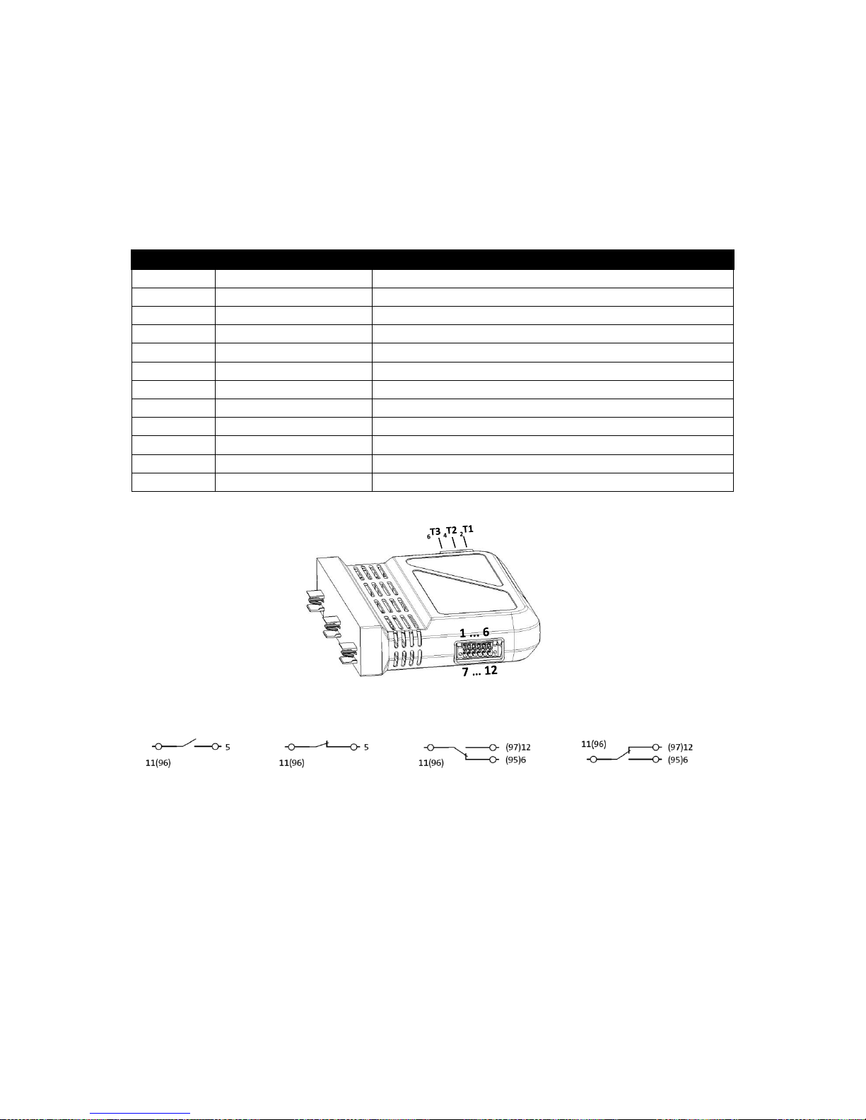
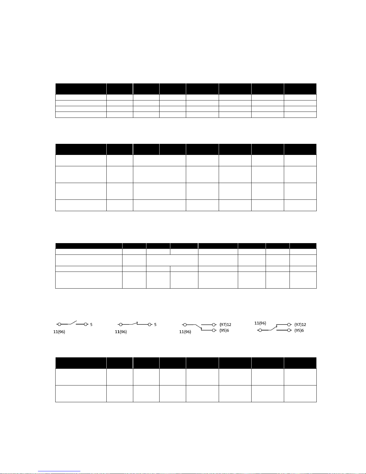
5.1 Connections
Terminal assignment control cable
Connection
Designation
Function
1
Ui +24V DC
+24 V DC design control supply voltage
2
PE
Functional ground
3
E L2
Control input for L2
4
E (L1 + L2 + L3)
Control input for L1 + L2 + L3
5
Warning
Warning message output
6
(95) error
Error message output („on“)
7
Ui mass
Ground control supply voltage
8
E L1
Control input for L1
9
E L3
Control input for L3
10
Mass inputs
Ground control inputs L1 + L2 + L3
11
(96) Warning + Error
Voltage input for message outputs
12
(97) error
Error message output („off“)
L2
L3
L1
Signal relay:
1) Warning off 2) Warning on 3) Error on 4) Error off
Page 16
OMUS® user manual
Revision 8, March 2017
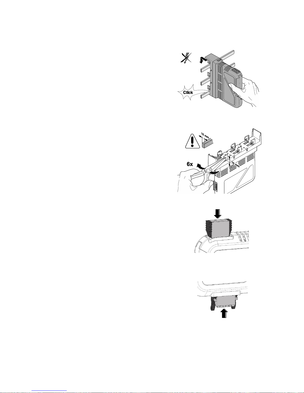
5.2 Installing and connecting the main circuits
Mounting on the busbar system:
Lock the complete module including the busbar
adapter to the rails. The electrical connection to
the three-phase conductors is made through
the adapter.
If necessary, adjust the busbar adapter's
feet for 10mm busbars beforehand.
CAUTION: Never carry out work when
the voltage is connected! Danger to life!
Connection plug:
Load plug:
Connect the load side conductors to the load
plug and lock it into the device.
Control plug:
Connect signal and control cables to the
control plug and lock it into the device.
Applying the operating voltage:
• Apply 24V DC operating voltage to the OMUS®!
• Apply voltage to the busbar system!
Page 17
OMUS® user manual
Revision 8, March 2017
5.3 Meaning of the LED indicators
• Auto(matic) mode: LEDs permanently green (compare chapter 6.2 Overview of display
functions)
• Warning: LEDs orange
• Error: LEDs red + OMUS® switched off
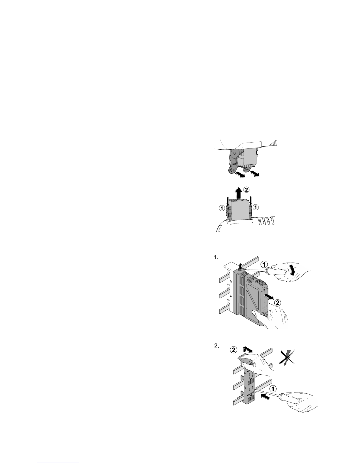
5.4 Disassembly and replacing devices
Disconnect power to the busbar system, obey safety instructions!
Remove the control plug:
Remove the load plug
Remove the OMUS® from the adapter
Remove the busbar adapter from the system:
Page 18
OMUS® user manual
Revision 8, March 2017
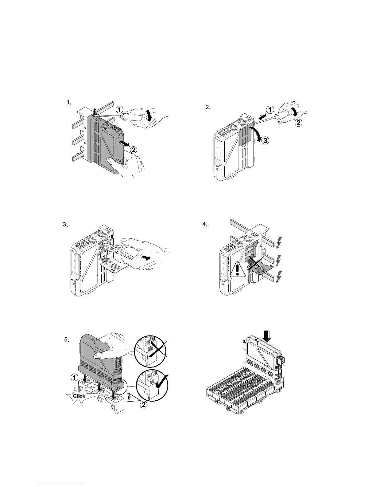
5.5 Replacing a fuse
Disconnect power to the busbar system, obey safety instructions!
Remove the OMUS® from the adapter: Open fuse cover:
Exchange fuse: Do not exchange the fuse before dismantling!
Snap the OMUS® onto the adapter: Snap the OMUS® onto the CrossBoard®:
Pay attention to the right position of the lock slide (compare assembly stage 5) and the reverse
polarity protection!
6.
Page 19

OMUS® user manual
Revision 8, March 2017
5.6 Checklist
Work through the following checklist at the end of commissioning and check all corresponding
points to guarantee the safe operation of the device.
Parameter
Description
Status
Fuse
Fuses in place and functional
Busbar adapter
Correct locking with the system
Load plug
Correct locking and cabling of the load plug
Control plug
Correct locking and cabling of the control plug
Control voltage
Operating voltage applied, power supply adequately designed
Functional ground
PE is connected to input 2 of the control plug
Voltage load
Supply voltage is applied
Switching variant
Suitable application (compare chapter 6.4)
LED status
Main LED and parameter LEDs show permanent green light
Warning
Warning signal relay wired and inactive
Error
Error signal relay wired and inactive
Actuation
Actuation within the prescribed parameters
Operating mode
Auto(matic) for using the control inputs or Hand (manual mode)
Current limit
Current limits set according to outlet cable
Min. load current
The load current is at least 2A in rated operation
Page 20
OMUS® user manual
Revision 8, March 2017
6 User interface
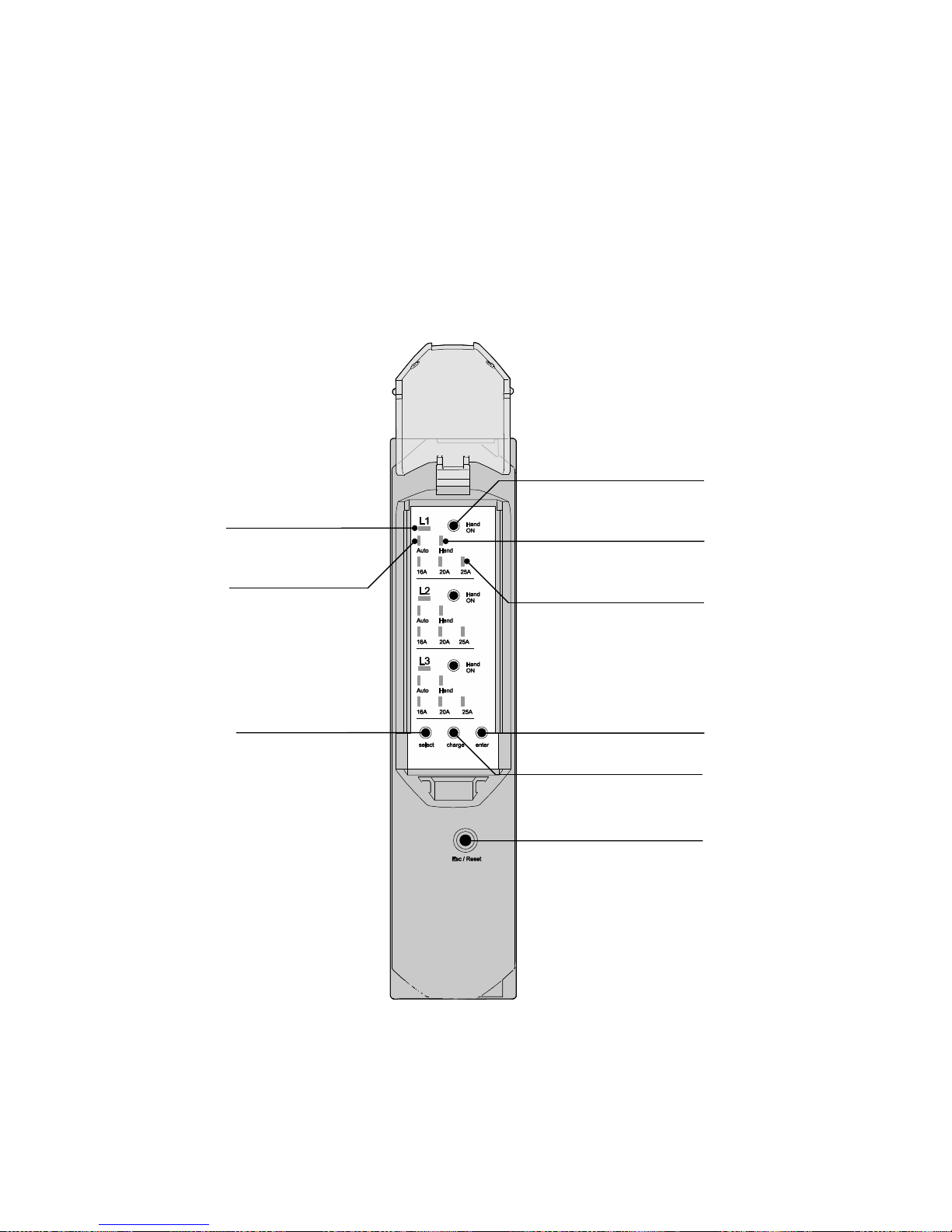
6.1 Front view
• Normal operation: LEDs permanently green (compare chapter 6.2 Overview of display
functions)
• Warning: LEDs orange
• Error: LEDs red + OMUS® switched off
Change button
Manual LED
Auto(matic) LED L1
Main LED L1
Current limits 16A, 20A, 25A
Hand ON button L1
Enter button
Select button
Esc / Reset button
Page 21
OMUS® user manual
Revision 8, March 2017
6.2 Overview of display functions
The detailed description of the different operation modes is shown in chapter 8.
Auto(matic) mode (main LED: green)
Status
Main LED
Auto LED
Manual
LED
Current limits
Warning
Error
Load
Factory setting
Green
Green
Off
Green (16A)
Off 1)
Off 4)
Switched
Auto(matic) mode 16A
Green
Green
Off
Green (16A)
Off 1)
Off 4)
Switched
Auto(matic) mode 20A
Green
Green
Off
Green (20A)
Off 1)
Off 4)
Switched
Auto(matic) mode 25A
Green
Green
Off
Green (25A)
Off 1)
Off 4)
Switched
Warnings (main LED: orange)
Status
Main LED
Auto LED
Manual
LED
Current limits
Warning
Error
Load
Phase failure /
fuse blown
affected
orange
affected green
affected flash
green
On 2)
Off 4)
Switched
Load failure
(current <2A)
affected
flash
orange
affected green
affected off
On 2)
Off 4)
Switched
Current limit reached
affected
flash
orange
affected green
affected flash
green
On 2)
Off 4)
Switched
Temperature limit
(approx. 65 °C)
flash
orange
affected green
affected
green
On 2)
Off 4)
Switched
Errors (main LED: red)
Acknowledge by pressing ESC/Reset button or disconnecting the 24 V supply
Status
Main LED
Auto LED
Manual LED
Current limits
Warning
Error
Load
No 24V operating voltage
Off
Off
Off
Off
Off 1)
On 3)
Off
Overcurrent (approx. 15%)
affected
flash red
affected green
affected flash
green
Off 1)
On 3)
affected
Off
Overtemperature (approx. 80 °C)
flash red
Off
Off
Off
Off 1)
On 3)
Off
Current without actuation,
device potentially defective,
external switch off required
affected
flash red
Green
Red
affected flash
green
Off 1)
On 3)
affected
permanent
on
Signal relay:
1) Warning off 2) Warning on 3) Error on 4) Error off
Manual mode (for commissioning)
Status
Main LED
Auto LED
Manual
LED
Current limits
Warning
Error
Load
Manual mode
16A/20A/25A
inactive
Green
Off
Green
Affected
green
Off 1)
Off 4)
Off
Manual mode
16A/20A/25A
active
Green
Off
Green
Affected
green
Off 1)
Off 4)
Switched
Page 22
OMUS® user manual
Revision 8, March 2017
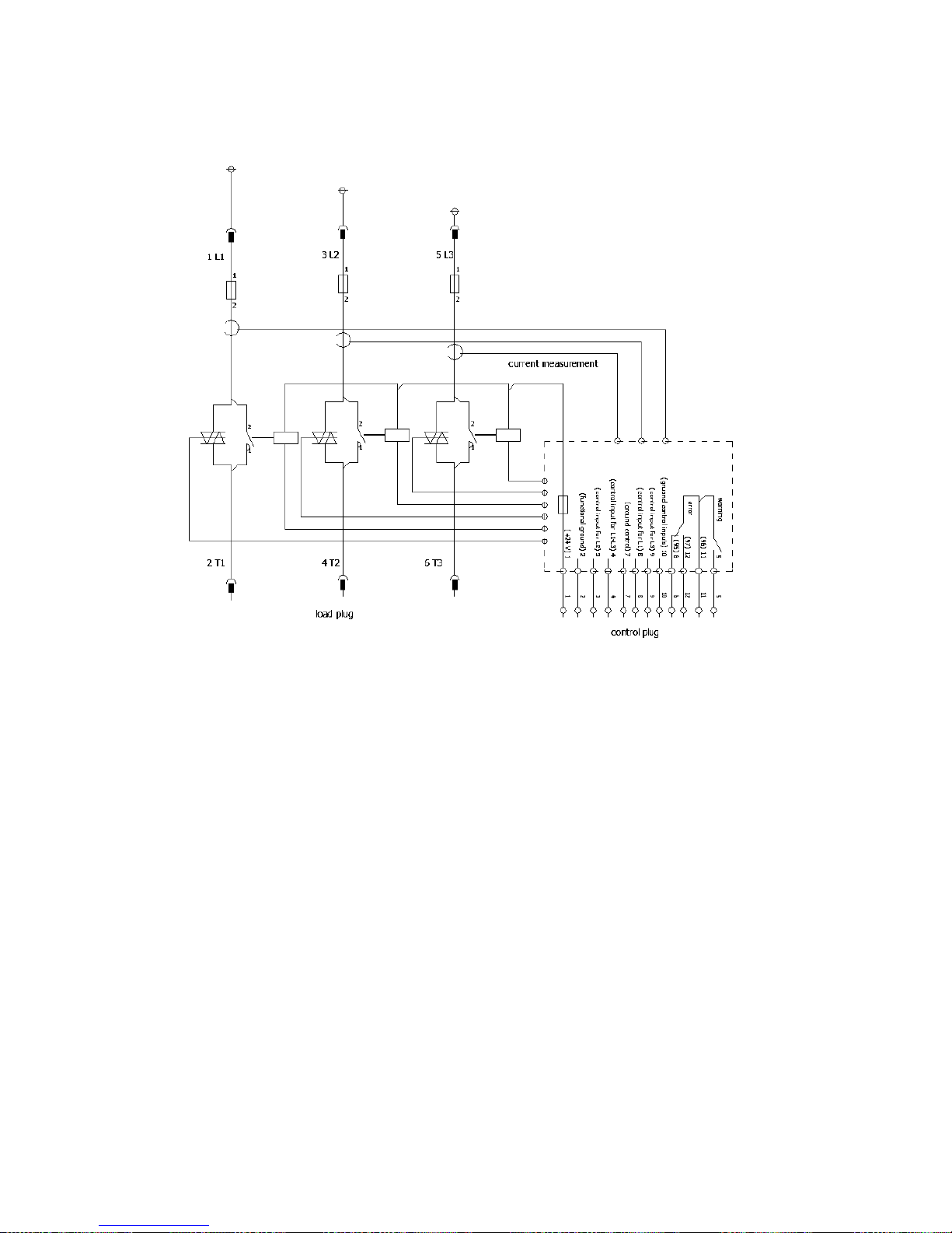
6.3 Eplan symbol
Page 23
OMUS® user manual
Revision 8, March 2017
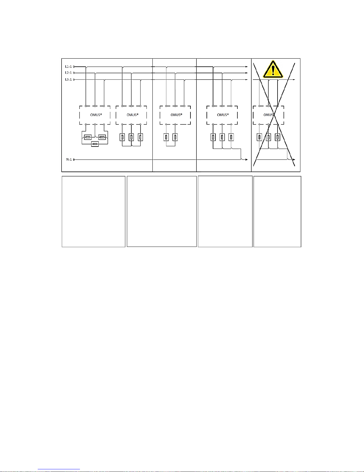
6.4 Switching variants
For applications
without a neutral
conductor, the usage
of the 3-phase input
L1+L2+L3 (input 4
control plug) is
mandatory!
Usage of load
against neutral
conductor offers
switching as
required
(individually or
together).
Not suitable for
operating in
single-phase
networks
For 2-pole usage without
neutral conductor, the
usage of the 3-phase
input L1+L2+L3 (input 4
control plug) is
mandatory! The third
pole has to be in manual
mode!
Page 24

OMUS® user manual
Revision 8, March 2017
7 Configuration of OMUS®
The settings menu allows the user to configure OMUS® in line with the application. The setting
of the current limits at the levels 16A, 20A and 25A must be done by the user in accordance
with the requirements and limits of the installation.
The first operating mode available is auto(matic) mode, which is controlled via 24V DC inputs
(e.g. PLC). The second mode available is manual mode for commissioning, which is activated
by the Hand ON-button. Each phase can be set to an individual configuration.
The menu is called up by pressing the Select button and pressing again switches to the next
menu item. A continuous light displays the status set. The Change button in the selected
menu item should be used to change the settings. Pressing it multiple times allows you to
preselect all settings options for the present menu item. Selected settings flash green. Pressing
the Enter button applies the selected setting and returns you to the menu. Settings not
saved by pressing Enter will be lost.
You can leave the menu at any time by pressing the Esc / Reset button. The menu will also
be closed after the last menu item or once approximately 30s pass with no action by the user.
When leaving the menu all display LEDs will flash several times. The set parameters,
confirmed with Enter, will be applied and the outputs will be switched back to active. All settings
are saved on the device permanently. The settings are retained even if the 24 V operating
voltage is switched off.
Page 25
OMUS® user manual
Revision 8, March 2017
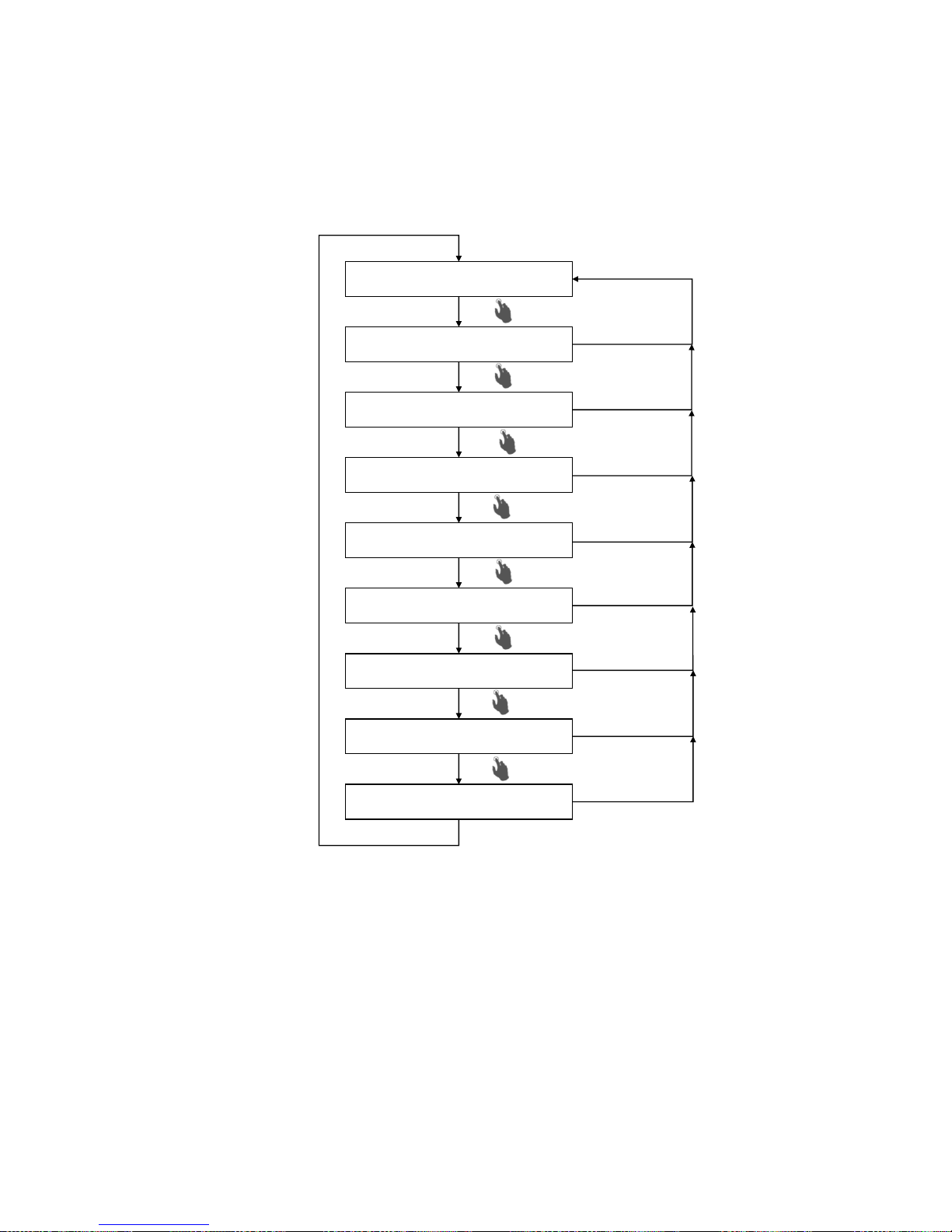
7.1 Menu structure
The menu structure is visualized in the following diagram. The following pages visually
describe the settings for single phase or all three phases.
Select
Select
Set 3-phase current limit
Set 3-phase operating mode
Select
Main display
Current limit L1
Operating mode L1
Current limit L2
Operating mode L2
Current limit L3
Operating mode L3
Select
Select
Select
Select
Select
30s / Reset
30s / Reset
30s / Reset
30s / Reset
30s / Reset
30s / Reset
30s / Reset
30s / Reset
Page 26
OMUS® user manual
Revision 8, March 2017
7.2 Three-phase settings
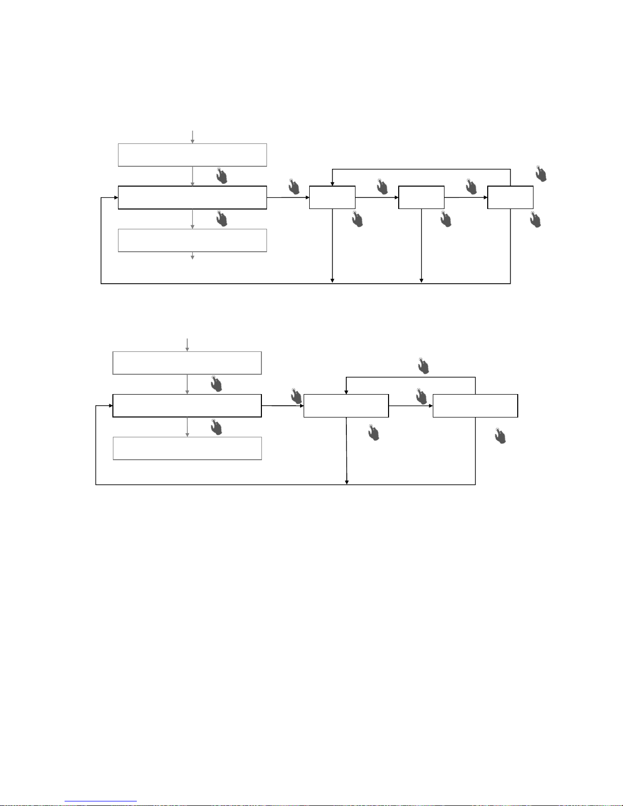
The three-phase setting of the current limits is pictured as follows:
The three-phase setting of the operating mode is pictured as follows:
Enter
Enter
Change
Change
Change
Select
Set 3-phase current limit
Set 3-phase operating mode
16A
20A
25A
Enter
Select
Main display
Change
Current limit saved in 3-phase
Enter
Enter
Change
Change
Select
Set 3-phase current limit
Set 3-phase operating mode
Manual 3-phase
Select
Auto 3-phase
Change
Operating mode saved in 3-phase
Set current limit L1
Page 27
OMUS® user manual
Revision 8, March 2017
7.3 Single-phase settings
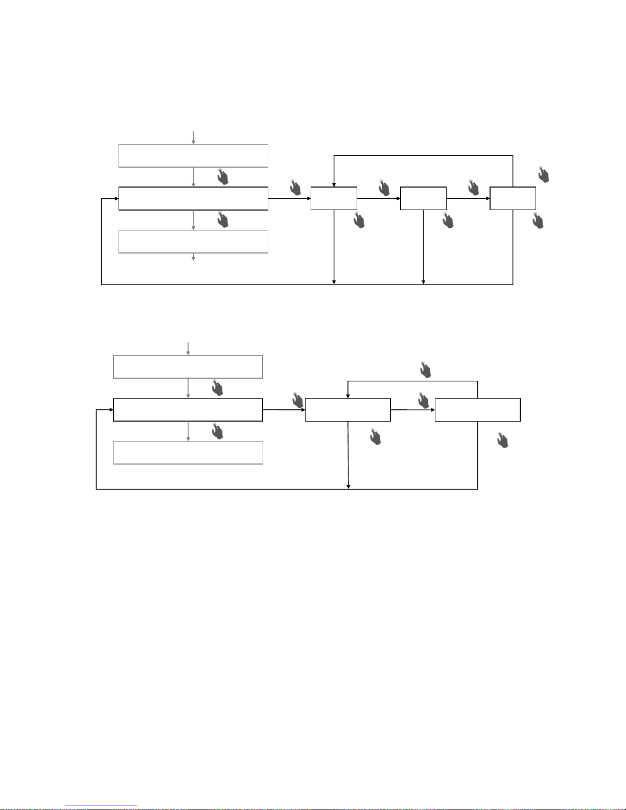
The single-phase setting of a current limit is pictured as follows:
The single-phase setting of an operating mode is pictured as follows:
The additional phase settings are carried out in the same way.
Enter
Enter
Change
Change
Change
Select
Set current limit L1
Set operating mode L1
16A
20A
25A
Enter
Select
Set 3-phase operating mode
Change
Current limit L1 saved
Enter
Enter
Change
Change
Select
Set current limit L1
Set operating mode L1
Manual L1
Select
Auto L1
Change
Operating mode L1 saved
Set current limit L2
Page 28

OMUS® user manual
Revision 8, March 2017
7.4 Restoring to factory settings
On delivery all phases are set to auto(matic) mode and the current limits to 16A. If you want
OMUS® to be reset to the delivery status, press Select and Enter button simultaneously.
This simultaneous pressing of the buttons will cause all LEDs to be illuminated and display the
successful restoration of the delivery status by flashing multiple times. All settings will be
overwritten and the factory status will configure OMUS® to three-phase in auto(matic)
mode with a current limit of 16A.
7.5 Standby
The device can be put in a Standby mode which will deactivate the outputs. To do this,
press and hold the Esc/Reset button for approx. 8s. All the outputs will be shut down.
All manual LEDs will flash orange, all other LEDs are off. The warning relay will issue a signal.
All settings are retained in Standby mode and no menu options are available. You can leave
the Standby mode again by pressing the Reset button for approx. 4s. The device cannot
be put in Standby mode, if there is an error.
Page 29

OMUS® user manual
Revision 8, March 2017
8 Function description
The device has various operating states:
• auto(matic) mode
• manual mode
• settings menu
• warning and error states
• standby mode
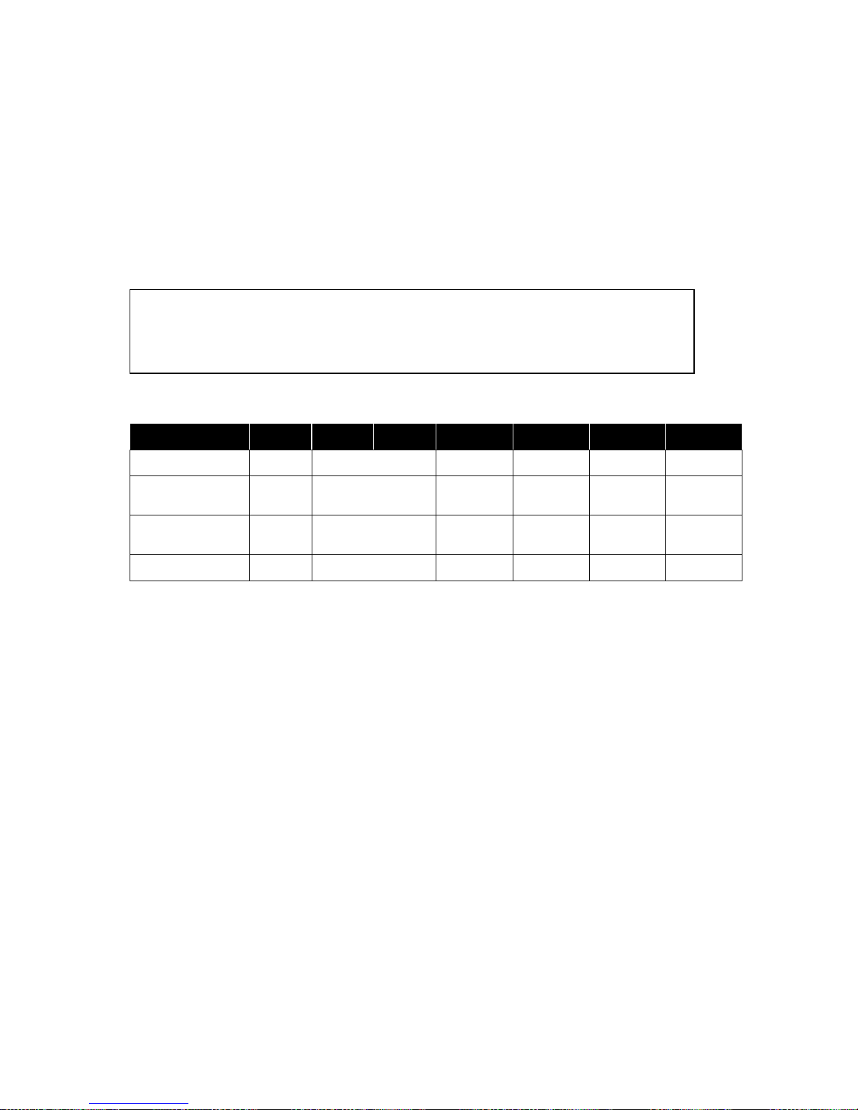
Warnings are issued during running operation. Errors turn the load off. The factory settings
can be restored by pressing the "select" + "enter" buttons simultaneously.
8.1 Auto(matic) mode
The device is in auto(matic) mode when it is used properly and there are no warnings or errors.
All main LEDs are permanently illuminated green as are the selected settings. In auto(matic)
mode, the outputs are actuated according to the input signals. The present switching status
is not displayed! The various operating parameters are continuously monitored. You can
switch to the settings menu from auto(matic) mode anytime.
Auto(matic) mode (main LED: green)
Status
Main LED
Auto LED
Manual
LED
Current limits
Warning
Error
Load
Factory setting
Green
Green
Off
green (16A)
Off 1)
Off 4)
Switched
Auto(matic) mode 16A
Green
Green
Off
green (16A)
Off 1)
Off 4)
Switched
Auto(matic) mode 20A
Green
Green
Off
green (20A)
Off 1)
Off 4)
Switched
Auto(matic) mode 25A
Green
Green
Off
green (25A)
Off 1)
Off 4)
Switched
8.2 Settings menu
The normal working functions are deactivated in the settings menu. The load is turned off.
8.3 Manual mode
If manual mode is activated via the settings menu, the "Hand ON" buttons switch on the
relevant phase. The "Hand ON" keys can be pressed simultaneously. In manual mode,
warnings and errors are treated in the same way as in auto(matic) mode. You can switch to
the settings menu from manual mode anytime.
Page 30
OMUS® user manual
Revision 8, March 2017
8.4 Warning
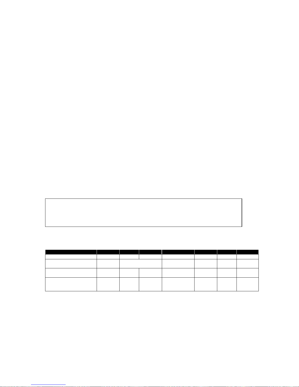
The following statuses will lead to a warning:
• Phase failure / Blown fuse
• Load failure
• Minor overcurrent - current limit reached
• Minor overtemperature - temperature warning above 65 °C
Warnings (main LED: orange)
Status
Main LED
Auto LED
Manual
LED
Current limits
Warning
Error
Load
Phase failure /
blown fuse
affected
orange
affected green
affected flash
green
On 2)
Off 4)
Switched
Load failure
(current <2A)
affected
flash
orange
affected green
affected off
On 2)
Off 4)
Switched
Minor overcurrent
(<15%)
affected
flash
orange
affected green
affected flash
green
On 2)
Off 4)
Switched
Minor overtemperature
(approx. 65°C)
Flash
orange
affected green
affected
green
On 2)
Off 4)
Switched
Phase failure / blown fuse
During operation OMUS® monitors the voltage on the busbar. If the measured voltage drops
below 42V AC, a phase failure is detected. The affected main LED will flash orange and the
set current limit LED will flash green. The warning relay issues a signal. The warning itself will
be cleared once the cause of the phase failure has been resolved.
Load failure
If the measured load current drops below 2 A, this is detected as a load failure. The main LEDs
for the affected phase will flash orange and the set current limit LED will turn off. The warning
relay will issue a signal. The warning itself will be cleared once the cause of the undercurrent
has been resolved. Ongoing operation will not be stopped.
PLC integration of warnings and avoidance of false alarms:
Warnings below 500ms should not be evaluated.
Signals below should be rejected.
Page 31
OMUS® user manual
Revision 8, March 2017
Minor overcurrent
If the measured load current reaches the set current limit, this is detected as a warning. The
main LED for the affected phase will flash orange and the set current limit LED will flash green.
The warning relay will issue a signal. The warning itself will be cleared once the cause of the
overcurrent has been resolved. Ongoing operation will not be stopped.
Minor overtemperature
If the temperature inside the hybrid switch exceeds 65°C, a warning is indicated. Main LEDs
will flash orange. The warning relay will issue a signal. The warning itself will be cleared once
OMUS® cools down. Ongoing operation will not be stopped.
8.5 Error
The Following parameters, monitored by OMUS® during operation, can lead to errors:
• No 24V control voltage
• Major Overcurrent- current limit exceeded by approx. 15%
• Major Overtemperature - temperature error above 80 °C
• Irregular current flow
Errors (main LED: red)
Acknowledge by pressing ESC/Reset button or disconnecting the 24 V supply
Status
Main LED
Auto LED
Manual LED
Current limits
Warning
Error
Load
No 24V control supply voltage
Off
Off
Off
Off
Off 1)
On 3)
Off
Major Overcurrent (>15%)
affected
flash red
Affected Green
affected flash
green
Off 1)
On 3)
affected
Off
Major Overtemperature
(approx. 80°C)
flash red
Off
Off
Off
Off 1)
On 3)
Off
Current without actuation,
device potentially defective,
external switch off required
affected
flash red
Green
Red
affected flash
green
Off 1)
On 3)
affected
switched
No 24V control voltage
If there is no 24V control supply voltage at OMUS® (input 1 or 7 at control plug), the error relay
will issue a signal.
PLC integration of errors and avoidance of false alarms:
Errors below 500ms should not be evaluated.
Signals below should be rejected.
Page 32

OMUS® user manual
Revision 8, March 2017
Major Overcurrent
If the measured load current exceeds the set current limit by more than 15%, the affected load
is shut down. In the affected phase, the main LED turns red and the set current limit LED will
flash green. The error relay continuously issues a signal. After the cause of the overcurrent
has been resolved, the error message must be acknowledged (press Esc/Reset) to resume
operation again.
Major Overtemperature
If the internal temperature of the hybrid switch exceeds 80°C, an error is indicated. All main
LEDs will flash red. The error relay continuously issues signal. All outputs are shut down for
self-protection. After cooldown, the error message must be acknowledged (press Esc/Reset
button) to resume operation again.
Irregular current flow
If the electronics detect an irregular current flow to the load, it assumes a defect in the hybrid
switch. In the affected phase, the main LED turns red and the set current limit LED will flash
green. The error relay will continuously issue a signal. The load must be switched off by an
external switchgear in order to interrupt the current flow. If the error continues after
acknowledgement (press Esc/Reset), the hybrid switch must be replaced.
8.6 Acknowledgement of messages
If the cause of a warning has been resolved, the warning itself will be cleared. Error messages
have to be acknowledged by pressing Esc/Reset. The cause of an error must be resolved first
in this instance. The acknowledgement of an error by interrupting the 24 V operating voltage
may only take place 500ms after switching off the load.
8.7 Interruption
If the 24V operating voltage is interrupted, the loads are shut down. All LEDs are off and the
error relay will issue a signal. The operational switching by disconnecting the 24 V
operating voltage is not allowed! Non-observance will lead to higher wear of the hybrid
switch.
Page 33

OMUS® user manual
Revision 8, March 2017
9 Technical data
Ambient conditions
Ambient temperature
-5°C to 35°C in control cabinet;
for temperatures up to 55°C or group layout see
derating
Pollution degree
2, in the housing
Overvoltage category
II, Load level
Main circuits
Switching principle
3 separate switches with bypass L1, L2, L3
Number of main circuits
3 independent circuits L1, L2 and L3 for resistive
loads
Design operating voltage Ue to IEC60947-1
400V AC, 50Hz
Maximum power loss (relays permanently on)
20W
Setting continuous current limits
16A, 20A, 25A, warning when limits are reached
Overload protection
shutdown if exceeded by more than 15%
Design operating current I
e
Utilisation category AC-51 to IEC 60947-4-3
25A 3× single-phase, 25A 1× three-phase
Minimum load current I
nc min
2A
Coordination type 1, system protection
30kA, 400V
IP protection type
IP20
Control circuit and main circuits isolation
U
imp
2.5kV
Isolation function EN60947-1 2.1.19
no position indicator for main contacts, device
has no isolation function
Leakage current (input, output) separate
Less than 2mA (no electrical isolation)
Residual voltage during switching
1,2V max. 10ms
Temperature protection in the device
65°C warning, 80°C shutdown
Input protection circuits
Fuses
IEC: 3× 10×38, 32A gG, 400V
UL: 3× Class CC 30A, 600V
varistors 510V
UL approval
File E483362 Vol.1 Sec. 1
Type No. OM25-H cULus listed
Current / Voltage ratings
20A 3x single-phase, 20A 1x 3-phase 480VAC
Minimum load current I
nc min
2A
Short Circuit Current Rating SCCR to UL 508a
30kA, 480V with Class CC 30A
Maximum surrounding air temperature
40°C
Maximum surface temperature
55°C
Pollution degree
2
Maximum busbar temperature
110°C
Page 34

OMUS® user manual
Revision 8, March 2017
Timing
Max. switching frequency
1Hz
Min. duration of actuation ports
100 ms
Min. switch on duration of load
100 ms
Min. switch off duration of load
100 ms
Max. switch on delay
80ms
Max. switch off delay
80ms
Control circuits
Design control supply voltage US to
IEC 60947-1
UL 508
24V DC
26.5V DC
Control supply voltage, noise level "Safe off"
< 5V DC
Design control supply current to IEC 60947-1
≤ 150mA
Control input L1, L2, L3, L1+L2+L3
Switching level "Low"
Switching level "Safe off"
Switching level "High"
Input current
– 3 to 9.6 V DC
< 5V DC
19.2V – 30V DC
≤ 3mA
Check-back output
Warning message
Floating contact, 1 normally open contact
Max. switching voltage
24V AC/DC
Max. continuous load current Io
0.5A
Error signal
Floating contact, 1 changeover contact
Max. switching voltage
48V AC/DC
Max. continuous load current Io
1A
Front controls
Buttons Select, Change, Enter
Parameter setting
Manual button ON
Outputs switched on in manual mode
Main and Auto LED
Green = OK; Orange = Warning; Red = Error
Current limit LED
Continuous current limit value 16A, 20A, 25A
Esc / Reset button outside the hinged control
panel
Acknowledgement of errors
Drilled hinged cover
enables sealing
Connection cross-sections
Connection
Conductor
type
IEC:
UL
3-pin plug connector with spring terminals
Cu rm, f
1.5 – 6mm²
AWG16 – AWG8
3-pin plug connector with screw terminals
Cu rm, f
1.5 – 6mm²,
0.5–0.8Nm
AWG16 – AWG8
7lb-in
12-pin control plug with spring terminals
Cu f
0.2 –
1.5mm²
AWG24 – AWG16
Page 35
OMUS® user manual
GHV Trading, spol. s r.o.
Edisonova 3, 612 00, Brno
Česká Republika
Tel.: +420 541 235 532-4
Tel.: +420 541 235 386
e-mail: [email protected]
http://www.ghvtrading.cz
Derating relative to 25A continuous current through busbar system
according to IEC 61439-2
Installation ambient temperature up to
35°C
45°C
55°C
Single installation/Gap ≥ 36mm
RDF = 1.0
RDF = 0.9
RDF = 0.8
Layout with gap ≥ 9mm
RDF = 0.9
RDF = 0.8
RDF = 0.7
Side-by-side layout, gap 0mm (4 devices)
RDF = 0.8
RDF = 0.7
RDF = 0.6
Measurement with fuses 32A gG, load plug with screw terminals, busbar temperature 70°C
Derating relative to 25A continuous current through CrossBoard® according
to IEC 61439-2
Installation ambient temperature up to
35°C
45°C
55°C
Single installation/Gap ≥ 36mm
RDF = 1.0
RDF = 0.9
RDF = 0.8
Side-by-side layout, gap 0mm
RDF = 0.6
RDF = 0.54
RDF = 0.48
Measurement with CrossBoard® CB405, fuses 32A gG, load plug with screw terminals
Slovenská Republika
Tel.: +421 255 640 293
Tel.: +421 948 528 908
e-mail: [email protected]
http://www.ghvtrading.sk
 Loading...