

Page 1
BROOME10
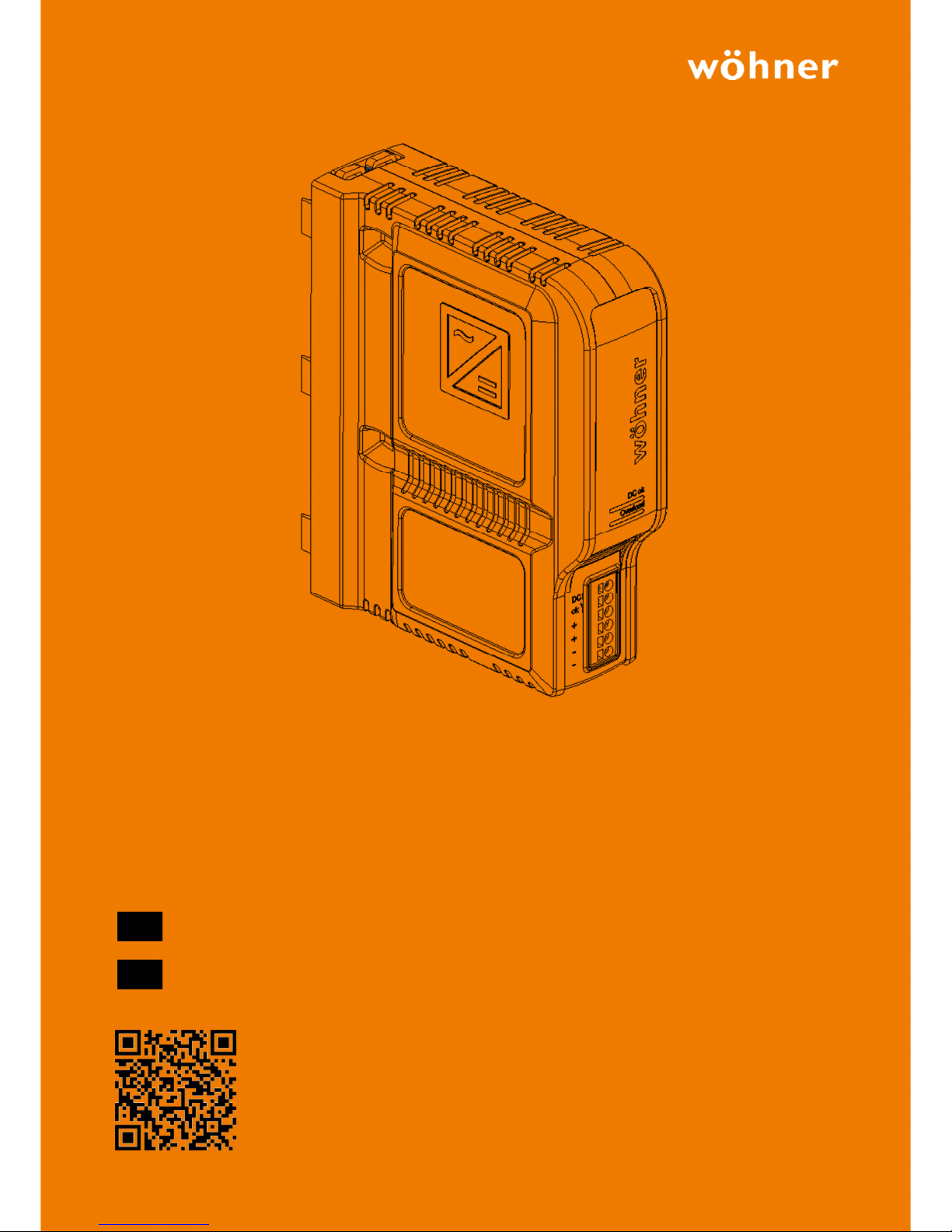
BROOME10 CrossBoard®
24Vdc / 10A Power Supply
Revision 1, November 2017
Bedienungsanleitung – 24Vdc / 10A Netzteil
Operating Instructions – 24Vdc / 10A Power Supply
Erfahren Sie mehr über BROOME10 auf unserer Website.
Learn more about BROOME10 at our website.
Apprenez-en davantage sur le BROOME10 sur notre site Internet.
Potete trovare ulteriori informazioni su BROOME10 alla nostra homepage.
Encontrará más información sobre BROOME10 en nuestra página web.
DE
GB
Page 2
Revision 1, Stand Nov. 2017 2
Deutsch.
A
LLGEMEINE BESCHREIBUNG
Das BROOME10 ist ein industrietaugliches Netzteil für 3-phasige Netze zur Verwendung auf dem CrossboardSammelschienensystem der Firma Wöhner. Es liefert eine potentialfreie, stabilisierte und galvanisch getrennte SELV / PELVAusgangsspannung.
Die herausragendsten Merkmale des BROOME10 sind der hohe Wirkungsgrad, die hohe Immunität gegen Transienten und
Spannungsspitzen, die erweiterte Einschaltstrombegrenzung, die aktive Leistungsfaktorkorrektur sowie der große
Betriebstemperaturbereich.
Alle Werte sind typische Werte bei 400VAC, 50Hz Eingangsspannung, 24V, 10A Ausgangslast und 25 ° C Umgebungstemperatur
und nach 5 Minuten Einlaufzeit, sofern nicht anders angegeben.
Technische Daten
Ausgangsspannung DC 24V 0/+6% über den gesamten Lastbereich
Spannungsregelung -
Ausgangsstrom 10A Unter +50°C Umgebung
5A Bei +70°C Umgebung
Derating linear zwischen +50°C und +70°C
Eingangsspannung AC AC 380-480V -10%/ +15%
Netzfrequenz 50-60Hz ±6%
Eingangsstrom AC 0,77 / 0,62A Bei 400 / 480Vac
Leistungsfaktor 0,70 / 0,73 Bei 400 / 480Vac
Eingang Einschaltstrom 1,5 / 1,5Apk Bei 400 / 480Vac
Wirkungsgrad 94,9 / 94,8% Bei 400 / 480Vac
Verlustleistung 12,8 / 13,2W Bei 400 / 480Vac
Überbrückungszeit 20 / 20ms Bei 400 / 480Vac
Temperaturbereich -25°C bis +70°C
Größe (B x H x T) 45x160x130mm
Gewicht 550g / 1.21lb
B
ESTELLNUMMER
BROOME10 CrossBoard®
36200
P
RÜFZEICHEN
Einzelheiten und vollständige Zulassungsliste finden Sie in Abschnitt 18.
UL 61010-2-201
IND. CONT. EQ.
Page 3

Revision 1, Stand Nov. 2017 3
Deutsch.
I
NDEX
Seite Page
1. Verwendungszweck ..............................................4
2. Installationsanforderungen ...................................4
3. AC-Eingang ...........................................................5
4. Einschaltstrom ......................................................6
5. Ausgang ................................................................7
6. Netzausfall-Überbrückungszeit .............................8
7. DC-OK Relais Kontakt ............................................8
8. Wirkungsgrad und Verluste ...................................9
9. Zuverlässigkeit .................................................... 10
10. MTBF ................................................................... 10
11. Anschlussklemmen und Verdrahtung .................. 11
12. Funktionsdiagramm ............................................ 12
13. Frontansicht und Bedienelemente ....................... 12
14. EMV .................................................................... 13
15. Umgebung .......................................................... 14
16. Sicherheitsmerkmale und Schutzfunktionen ....... 15
17. Spannungsfestigkeit............................................ 16
18. Zulassungen ........................................................ 16
19. Abmessungen und Gewicht ................................. 17
20. Anwendungshinweise ......................................... 18
20.1. Induktive und kapazitive Lasten ................. 18
20.2. Serienschaltung ......................................... 18
20.3. Parallelbetrieb zur Leistungserhöhung ...... 18
1. Intended Use ...................................................... 21
2. Installation Requirements .................................. 21
3. AC-Input ............................................................. 22
4. Input Inrush Current ........................................... 23
5. Output ............................................................... 24
6. Hold-up Time ..................................................... 25
7. DC-OK Relay Contact .......................................... 25
8. Efficiency and Power Losses ................................ 26
9. Lifetime Expectancy ............................................ 27
10. MTBF .................................................................. 27
11. Connection Terminals and Wiring ....................... 28
12. Functional Diagram ............................................ 29
13. Front Side and User Elements ............................. 29
14. EMC ................................................................... 30
15. Environment ...................................................... 31
16. Safety and Protection Features ........................... 32
17. Dielectric Strength .............................................. 33
18. Norms and Approvals ......................................... 33
19. Physical Dimensions and Weight ........................ 34
20. Application Notes ............................................... 35
20.1. Back-feeding Loads ................................... 35
20.2. Series Operation ........................................ 35
20.3. Parallel Use to Increase Output Power ...... 35
Die in diesem Dokument enthaltenen Informationen sind zum Zeitpunkt der Veröffentlichung nach bestem Wissen und
Erfahrung zusammengetragen. Sofern nicht ausdrücklich etwas anderes vereinbart wurde, stellen diese Informationen keine
Garantie im rechtlichen Sinn des Wortes dar. Da sich der Stand unserer Kenntnisse und Erfahrungen ständig ändert, unterliegen
die Angaben in diesem Datenblatt einer Überarbeitung. Wir bitten Sie daher, immer die neueste Ausgabe dieses Dokuments zu
verwenden (konsultieren Sie Wöhner).
Kein Teil dieses Dokuments darf ohne unsere vorherige schriftliche Genehmigung in irgendeiner Form reproduziert oder
verwendet werden.
T
ERMINOLOGIE UND ABKÜRZUNGEN
PE und Symbol
PE ist die Abkürzung für Protective Earth und hat die gleiche Bedeutung wie das Symbol .
Erde, Ground
Dieses Dokument verwendet den Begriff “Erde”, der dem US-Begriff “ground” entspricht.
T.b.d.
To be defined, Wert oder Beschreibung werden später folgen.
AC 400V
Eine Zahl, die mit AC oder DC vor dem Wert angezeigt wird repräsentiert eine Nennspannung mit
Standardtoleranzen (normalerweise ±15%).
z.B.: DC 12V beschreibt eine 12V-Batterie, unabhängig davon, ob sie voll (13.7V) oder leer (10V) ist.
400Vac
Eine Zahl mit der Einheit (Vac) am Ende ist eine Momentaufnahme ohne zusätzliche Toleranzen.
50Hz vs. 60Hz
Solange nicht anders angegeben, sind AC 400V-Parameters bei 50Hz Netzfrequenz gültig. AC 480V-
Parameters sind für eine Netzfrequenz von 60Hz gültig.
darf
Ein Schlüsselwort, das die Flexibilität der Wahl ohne implizite Referenz anzeigt.
soll
Ein Schlüsselwort, das eine verpflichtende Anforderung angibt.
sollte
Ein Schlüsselwort, das die Flexibilität der Wahl mit einer stark bevorzugten Implementierung angibt.
Page 4

Revision 1, Stand Nov. 2017 4
Deutsch.
1. V
ERWENDUNGSZWECK
Dieses Gerät ist für den Einbau in ein Gehäuse vorgesehen und ist für den allgemeinen Gebrauch vorgesehen, z. B. in industriellen
Steuerungs-, Büro-, Kommunikations- und Messgeräten.
Verwenden Sie dieses Gerät nicht in Geräten, in denen eine Fehlfunktion zu schweren Verletzungen oder zur Gefährdung von
Menschenleben führen kann.
2. I
NSTALLATIONSANFORDERUNGEN
Gefahr von Stromschlägen, Feuer, Verletzungen oder Tod.
- Schalten Sie das Gerät aus, bevor Sie am Gerät arbeiten. Gegen unbeabsichtigtes Wiedereinschalten schützen.
- Stellen Sie sicher, dass die Verkabelung korrekt ist, indem Sie alle lokalen und nationalen Vorschriften befolgen.
- Modifizieren oder reparieren Sie das Gerät nicht.
- Öffnen Sie das Gerät nicht, da hohe Spannungen im Inneren vorhanden sind.
- Achten Sie darauf, dass keine Fremdkörper in das Gehäuse gelangen.
- Nicht in nassen Umgebungen oder in Bereichen verwenden, in denen Feuchtigkeit oder Kondensation zu erwarten ist.
- Berühren Sie das Gerät nicht im eingeschalteten Zustand oder unmittelbar nach dem Ausschalten. Heiße Oberflächen können
Verbrennungen verursachen
Befolgen Sie die folgenden Installationsanforderungen:
- Installieren Sie das Gerät in einem Gehäuse, das Schutz gegen elektrische, mechanische und Brandgefahr bietet.
- Dieses Gerät darf nur von qualifiziertem Personal installiert und in Betrieb genommen werden.
- Schließen Sie das Gerät nicht an, solange die Eingangsspannung anliegt.
- Verwenden Sie das Gerät in einer kontrollierten Umgebung. Verwenden Sie das Gerät nicht in Bereichen mit
Verschmutzungsgrad 3 ohne zusätzlichen Schutz oder in Anwendungen, in denen ein Schutzgrad besser als IP30 erforderlich
ist.
- Das Gerät ist für die Konvektionskühlung ausgelegt und benötigt keinen externen Lüfter. Den Luftstrom nicht behindern und
das Lüftungsgitter nicht verdecken.
- Halten Sie die folgenden Mindestinstallationsabstände ein, wenn das Gerät dauerhaft mit mehr als 50% des Nennstroms
belastet wird: 40 mm oben, 20 mm unten, 0 mm links und rechts.
- Stellen Sie sicher, dass die Verkabelung korrekt ist, indem Sie alle lokalen und nationalen Vorschriften befolgen. Verwenden
Sie geeignete Kupferkabel, die für eine Mindestbetriebstemperatur von 60 °C für Umgebungstemperaturen bis + 45 °C, 75 °C
für Umgebungstemperaturen bis + 60 °C und 90 °C für Umgebungstemperaturen bis + 70 °C ausgelegt sind. Stellen Sie
sicher, dass alle Litzen eines feindrähtigen Leiters in die Klemmenverbindung eintreten.
- Dieses Gerät enthält keine zu wartenden Teile. Die Auslösung einer internen Sicherung wird durch einen internen Defekt
verursacht. Wenn während der Installation oder des Betriebs Schäden oder Fehlfunktionen auftreten sollten, schalten Sie das
Gerät sofort aus und senden Sie es zur Überprüfung an das Werk.
- Das Gerät ist ohne zusätzliche Schutzeinrichtung für Zweigstromkreise bis zu t.b.d. A ausgelegt, geprüft und zugelassen.
Wenn eine externe Sicherung verwendet wird, dürfen keine Leistungsschalter verwendet werden, die kleiner als 6A B- oder
C-Charakteristik sind, um eine Fehlauslösung des Leistungsschalters zu vermeiden.
WARNING
Page 5
Revision 1, Stand Nov. 2017 5
Deutsch.
3. AC-E
INGANG
Das Gerät ist geeignet, um von TN-, TT- und IT-Netzen mit Wechselspannung versorgt zu werden. Es arbeitet auf einem
Dreiphasen-Netzsystem, verwendet jedoch nur zwei Zweige des Dreiphasensystems.
AC Eingang Nom. AC 380-480V -10% / +15%
AC Eingangsbereich Min. 342-552Vac Dauerbetrieb
Überspannungsfestigkeit Min. 630Vac Vorübergehend erlaubt
Min. 630-700Vac Für maximal 10s (nicht regelmäßig)
Min. 700-800Vac Für maximal 500ms (nicht regelmäßig)
Zulässige Spannung Phase zu Erde Max. 552Vac Kontinuierlich nach IEC 62477-1
Eingangsfrequenz Nom. 50–60Hz ±6%
Einschaltspannung Typ. 335Vac statisch, siehe Fig. 3-1
Abschaltspannung Typ. 325Vac statisch, siehe Fig. 3-1
Externer Eingangsschutz Siehe Empfehlungen im Kapitel 2.
AC 400V AC 480V
Eingangsstrom Typ. 0,77A 0,62A Bei 24V, 10A, siehe Fig. 3-3
Leistungsfaktor Typ. 0,70 0,73
Bei 24V, 10A, siehe Fig. 3-4
Nach DIN 40110-2 für 3-phasige Systeme
Einschaltverzögerung Typ. 200ms 200ms Siehe Fig. 3-2
Anstiegszeit Typ. 55ms 55ms
Bei 24V, 10A ohmsche Last, 0mF Lastkapazität, siehe
Fig. 3-2
Typ. 90ms 90ms
Bei 24V, 10A ohmsche Last, 10mF Lastkapazität, siehe
Fig. 3-2
Überschwingen beim Einschalten Max. 200mV 200mV siehe Fig. 3-2
Fig. 3-1
Eingangsspannungsbereich
Fig. 3-2
Einschaltverhalten, Definitionen
Turn-on
342
Rated
input range
max.
500ms
V
IN
P
OUT
800Vac552
Shut -dow n
700
max.
10s
Start-up
delay
Rise
Time
Overshoot
- 5%
Output
Voltage
Input
Voltage
L1 L2 L3
Fig. 3-3
Eingangsstrom zu Ausgangslast bei 24V
Fig. 3-4
Leistungsfaktor zu Ausgangslast
1 2 3 4 5 6 7 8 9
0
0.1
0.2
0.4
0.6
0.7
0.8A
Input Current, typ.
10A
Output Current
(a)
(b)
0
0.5
a) 400Vac
b) 480Vac
0.3
Power Factor, typ.
1 2 3 4 5 6 7 8 9 10A
0.3
0.4
0.5
0.6
0.7
0.8
Output Current
(a) 400Vac,
(b) 480Vac
(a)
(b)
Page 6
Revision 1, Stand Nov. 2017 6
Deutsch.
4. E
INSCHALTSTROM
Eine aktive Einschaltstrombegrenzungsschaltung begrenzt den Einschaltstromstoß nach dem Einschalten der
Eingangsspannung. Der Ladestrom der Entstörkondensatoren wird in den ersten Mikrosekunden nach dem Einschalten bleibt
unberücksichtigt.
AC 400V AC 480V
Einschaltstrom Max. 2Apeak 2Apeak Unabhängig von der Temperatur
Typ. 1.5Apeak 1.5Apeak Unabhängig von der Temperatur
Einschaltenergie Max. 1A²s 1A²s Unabhängig von der Temperatur
Fig. 4-1
Typisches Einschaltverhalten bei Nennlast, 400
Vac Eingang und 25 ° C Umgebungstemperatur
Input voltage 1kV/DIV
Output voltage 20V/DIV
Input current 1A/DIV
40ms/DIV
Page 7
Revision 1, Stand Nov. 2017 7
Deutsch.
5. A
USGANG
Ausgangsspannung Nom. 24V 0/+6%
Das Gerät verfügt über eine "Soft-Output-Regelcharakteristik" (Parallelbetrieb), um eine
Stromaufteilung auf mehrere Geräte zu erreichen, wenn diese parallel geschaltet sind. Die "SoftOutput-Regelcharakteristik" regelt die Ausgangsspannung so, dass die Spannung im Leerlauf ca. 4%
höher als bei 10A Last.
Einstellbereich - Nicht einstellbar
Netzausregelung Max. 10mV Zwischen 342 und 552Vac
Lastausregelung Typ. 1000mV Zwischen 0 und 10A, statischer Wert, siehe Fig. 5-1
Restwelligkeit Max. 50mVpp 20Hz bis 20MHz, 50Ohm
Ausgangsstrom Nom. 10A Bei Umgebungstemperaturen unter +50°C, siehe Fig. 15-1
Nom. 5A Bei +70°C Umgebungstemperatur, siehe Fig. 15-1
Überlastschutz Integriert
Elektronisch geschützt bei Leerlauf, Überlast und Kurzschluss. Im
Falle eines Schutzereignisses können hörbare Geräusche auftreten.
Kein externer Schutz erforderlich.
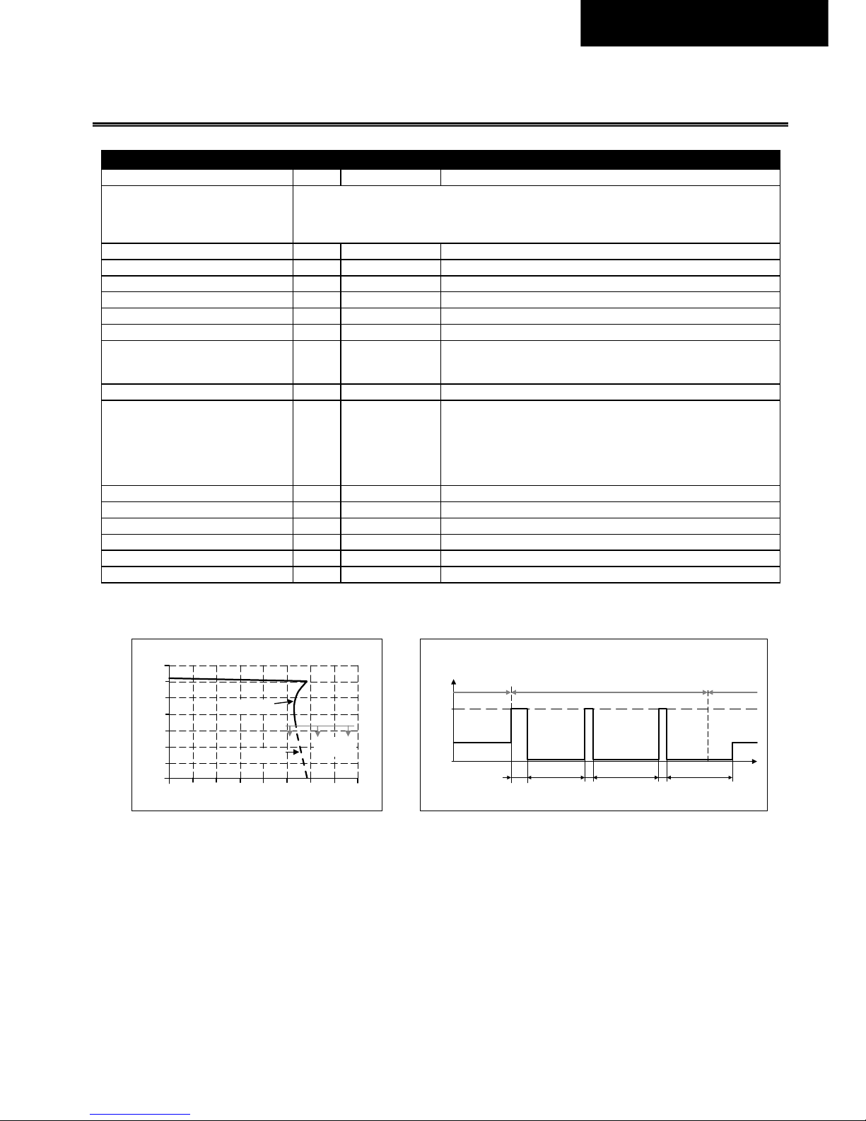
Überlastverhalten Dauerstrom Ausgangsspannung über 13Vdc, siehe Fig. 5-1
HiccupPLUS
Modus
Ausgangsspannung unter 13Vdc, siehe Fig. 5-1 und Fig. 5-2.
Das Netzteil liefert einen kontinuierlichen Ausgangsstrom für 2,8s.
Danach wird der Ausgang für 7s ausgeschaltet, bevor automatisch
ein neuer Startversuch über 1,2s durchgeführt wird. Dieser Zyklus
wird wiederholt, solange die Überlastung vorhanden ist. Wenn die
Überlast behoben wurde, arbeitet das Gerät normal.
Kurzschlussstrom Min. 10.4A1) Lastimpedanz <50mOhm
Max. 13A1) Lastimpedanz <50mOhm
Max. 5.0A Durchschnittsstrom (R.M.S.), Lastimpedanz <50mOhm
Ausgangskapazität Typ. 4 400µF Im Netzteil enthalten
Kapazitive Lasten Max. 1F Max. 2A zusätzliche Last während des Ladevorgangs
Induktive Lasten Unbegrenzt
1) Der Entladestrom der Ausgangskondensatoren ist nicht enthalten
Fig. 5-1
Ausgangsspannung zu Ausgangsstrom, typ.
Fig. 5-2
Kurzschluss am Ausgang, Hiccup
PLUS
Modus, typ.
Output Voltage
0
0 10
4
8
12
28V
16
20
24
16A62 4 8 12 14
Output Current
Hi ccup
PLUS
mode
Intermitted
current
Continuous
current
Output
Current
0
12.5A
7s7s 1.2s2.8s
t
Short -circuit
Normal
operat ion
Normal
operat ion
1.2s 7s
Page 8
Revision 1, Stand Nov. 2017 8
Deutsch.
6. N
ETZAUSFALL-ÜBERBRÜCKUNGSZEIT
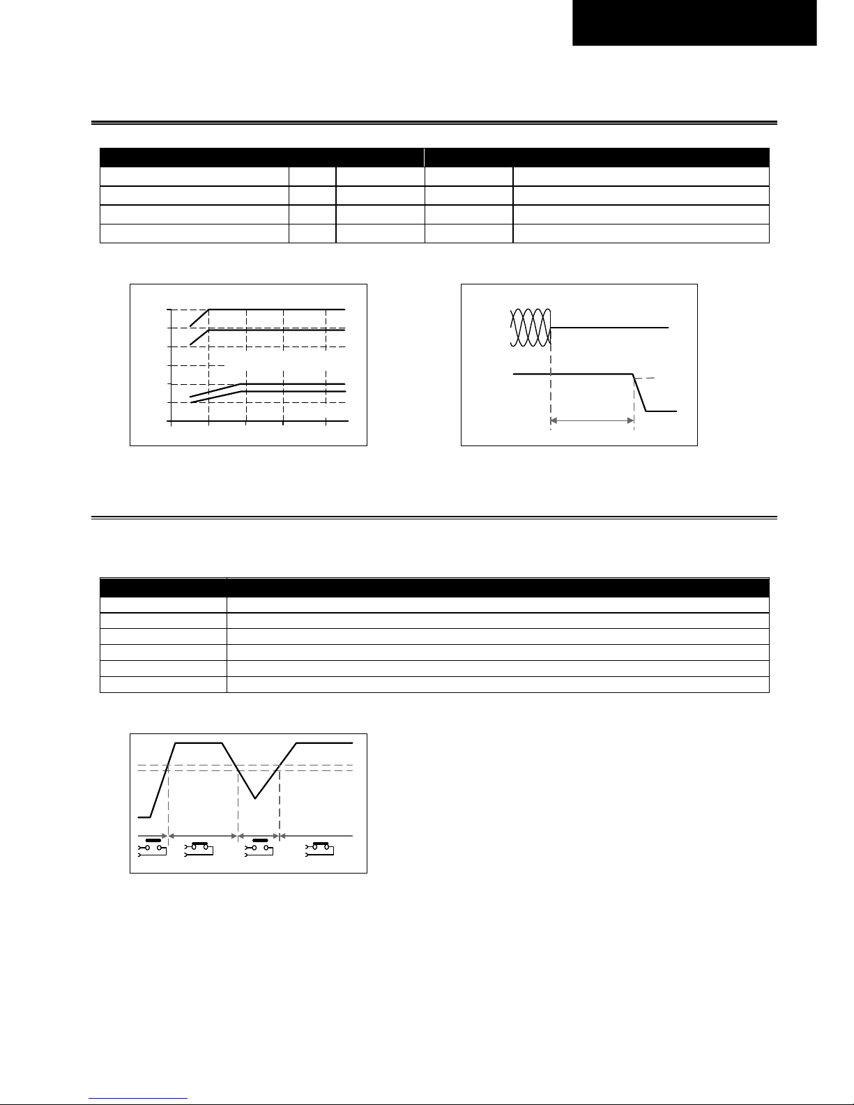
AC 400V AC 480V
Überbrückungszeit Typ. 60ms 60ms Bei 5A Laststrom
Min. 49ms 49ms Bei 5A Laststrom
Typ. 20ms 20ms Bei 10A Laststrom
Min. 16ms 16ms Bei 10A Laststrom
Fig. 6-1
Überbrückungszeit zu Eingangsspannung
Fig. 6-2
Abschaltverhalten, Definitionen
7. DC-OK R
ELAIS KONTAKT
Diese Schnittstelle überwacht die Ausgangsspannung an den Ausgangsklemmen eines Netzteils im Betrieb und ist unabhängig
von der rückgespeisten Spannung.
Kontakt schließt Sobald die Ausgangsspannung typischerweise 20V erreicht hat.
Kontakt öffnet Sobald die Ausgangsspannung typischerweise unter 19V fällt.
Schalthysterese 1V
Kontaktbelastbarkeiten Maximal 60Vdc 0,3A, 30Vdc 1A, 30Vac 0,5A, ohmsche Last
Minimale zulässige Belastung: 1mA bei 5Vdc
Isolationsspannung Siehe Spannungsfestigkeitstabelle in Kapitel 17.
Fig. 7-1
DC-ok Relaiskontakt Verhalten
0
10
20
30
60ms
320 360 400 440 480Vac
Input Voltage
40
50
Hold-up Time
a
b
c
d
a) 24V 5A typ.
b) 24V 5A min.
c) 24V 10A typ.
d) 24V 10A min.
- 5%
Hold-up Time
Output
Voltage
Input
Voltage
L1 L2 L3
20V
open openclosed closed
19V
Page 9
Revision 1, Stand Nov. 2017 9
Deutsch.
8. W
IRKUNGSGRAD UND VERLUSTE
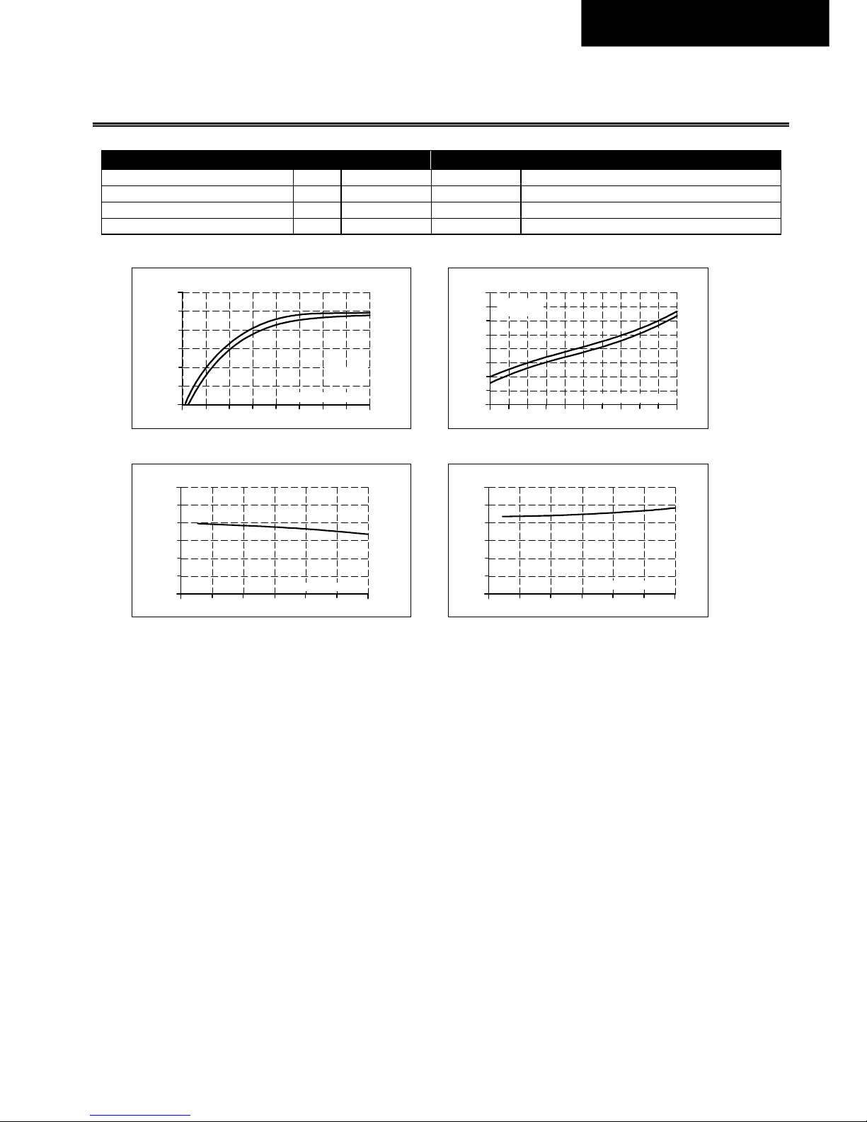
AC 400V AC 480V
Wirkungsgrad Typ. 94,9% 94,8% Bei 24V, 10A
Verluste Typ. 3,3W 4,0W Bei 24V, 0A
Typ. 7,6W 8,2W Bei 24V, 5A
Typ. 12,8W 13,2W Bei 24V, 10A
Fig. 8-1
Wirkungsgrad zu Ausgangsstrom, typ.
Fig. 8-2
Verluste zu Ausgangsstrom, typ.
Fig. 8-3
Wirkungsgrad zu Eingansgspannung bei 10A, typ.
Fig. 8-4
Verluste zu Eingangsspannung bei 10A, typ.
Efficiency
2
92
94
95
90
96%
10A4 7 86
Output Current
953
93
91
(a)
(a) 400Vac
(b) 480Vac
(b)
Power Losses
0 2 4 8 9 10A
0
2
6
8
12
14
16W
4
6107531
Output Current
(a)
(b)
(a) 400Vac
(b) 480Vac
Efficiency
320 360 400 440 480
96%
93.5
94.5
95.5
95.0
94.0
93.0
520
560Vac
Input Voltage
Power Losses
320 360 400 440 480
16W
6
10
14
12
8
4
520
560Vac
Input Voltage
Page 10
Revision 1, Stand Nov. 2017 10
Deutsch.
9. Z
UVERLÄSSIGKEIT
Die in der Tabelle angegebene Lebensdauer gibt die Mindestbetriebsstunden (Lebensdauer) an und wird durch die
Lebensdauererwartung der eingebauten Elektrolytkondensatoren bestimmt. Die Lebensdauer wird in Betriebsstunden
angegeben und entsprechend der Herstellerspezifikation des Kondensators berechnet. Der Hersteller der
Elektrolytkondensatoren garantiert eine maximale Lebensdauer von bis zu 15 Jahren (131 400h). Jede Zahl, die diesen Wert
überschreitet, ist eine berechnete theoretische Lebensdauer, die zum Vergleichen von Geräten verwendet werden kann.
AC 400V AC 480V
Lebenserwartung T.b.d. T.b.d. Bei 5A und 25°C
T.b.d. T.b.d. Bei 10A und 25°C
T.b.d. T.b.d. Bei 5A und 40°C
53 000h T.b.d. Bei 10A und 40°C
10. MTBF
MTBF steht für Mean Time Between Failure, die nach statistischen Gerätefehlern berechnet wird und die Zuverlässigkeit eines
Geräts angibt. Es ist die statistische Darstellung der Wahrscheinlichkeit, dass eine Einheit ausfällt und repräsentiert nicht
notwendigerweise die Lebensdauer eines Produkts. Die MTBF-Zahl ist eine statistische Darstellung der Wahrscheinlichkeit, dass
ein Gerät ausfällt. Eine MTBF-Zahl von z.B. 1 000 000h bedeutet, dass statistisch gesehen eine Einheit alle 100 Stunden ausfällt,
wenn 10 000 Einheiten im Feld installiert sind. Es kann jedoch nicht festgestellt werden, ob die ausgefallene Einheit für 50 000
Stunden oder nur für 100 Stunden in Betrieb war ist. Für diese Gerätetypen ist der MTTF-Wert (Mean Time To Failure) derselbe
Wert wie der MTBF-Wert.
AC 400V AC 480V
MTBF SN 29500, IEC 61709 T.b.d. T.b.d. Bei 10A und 40°C
T.b.d. T.b.d. Bei 10A und 25°C
MTBF MIL HDBK 217F T.b.d. T.b.d. Bei 10A und 40°C; Ground Benign GB40
T.b.d. T.b.d. Bei 10A und 25°C; Ground Benign GB25
T.b.d. T.b.d. Bei 10A und 40°C; Ground Fixed GF40
T.b.d. T.b.d. Bei 10A und 25°C; Ground Fixed GF25
Page 11

Revision 1, Stand Nov. 2017 11
Deutsch.
11. A
NSCHLUSSKLEMMEN UND VERDRAHTUNG
Die Klemmen sind IP20 fingersicher konstruiert und für field- sowie factory wiring geeignet.
Ausgang und DC-OK
Typ Push-in Klemmen
Volldraht Max. 2,5mm²
Litze Max. 2,5mm²
Litze mit Aderendhülsen T.b.d.
American Wire Gauge 24-12 AWG
Max. Leitungsdurchmesser (inklusive
Aderendhülse)
2,3mm
Abisolierlänge 10mm / 0,4Zoll
Schraubendreher 3,0mm Schlitzschraubendreher um die Feder zu öffnen
Anweisungen für die Verdrahtung:
a) Verwenden Sie geeignete Kupferkabel, die für minimale Betriebstemperaturen ausgelegt sind von:
60°C für Umgebungstemperatur bis 45°C und
75°C für Umgebungstemperatur bis 60°C und
90°C für Umgebungstemperaturen bis 70°C.
b) Beachten Sie die nationalen Installationsvorschriften und Regelungen!
c) Stellen Sie sicher, dass alle Einzeldrähte einer Litze in der Anschlussklemme stecken!
d) Aderendhülsen werden empfohlen.
Page 12
Revision 1, Stand Nov. 2017 12
Deutsch.
12. F
UNKTIONSDIAGRAMM
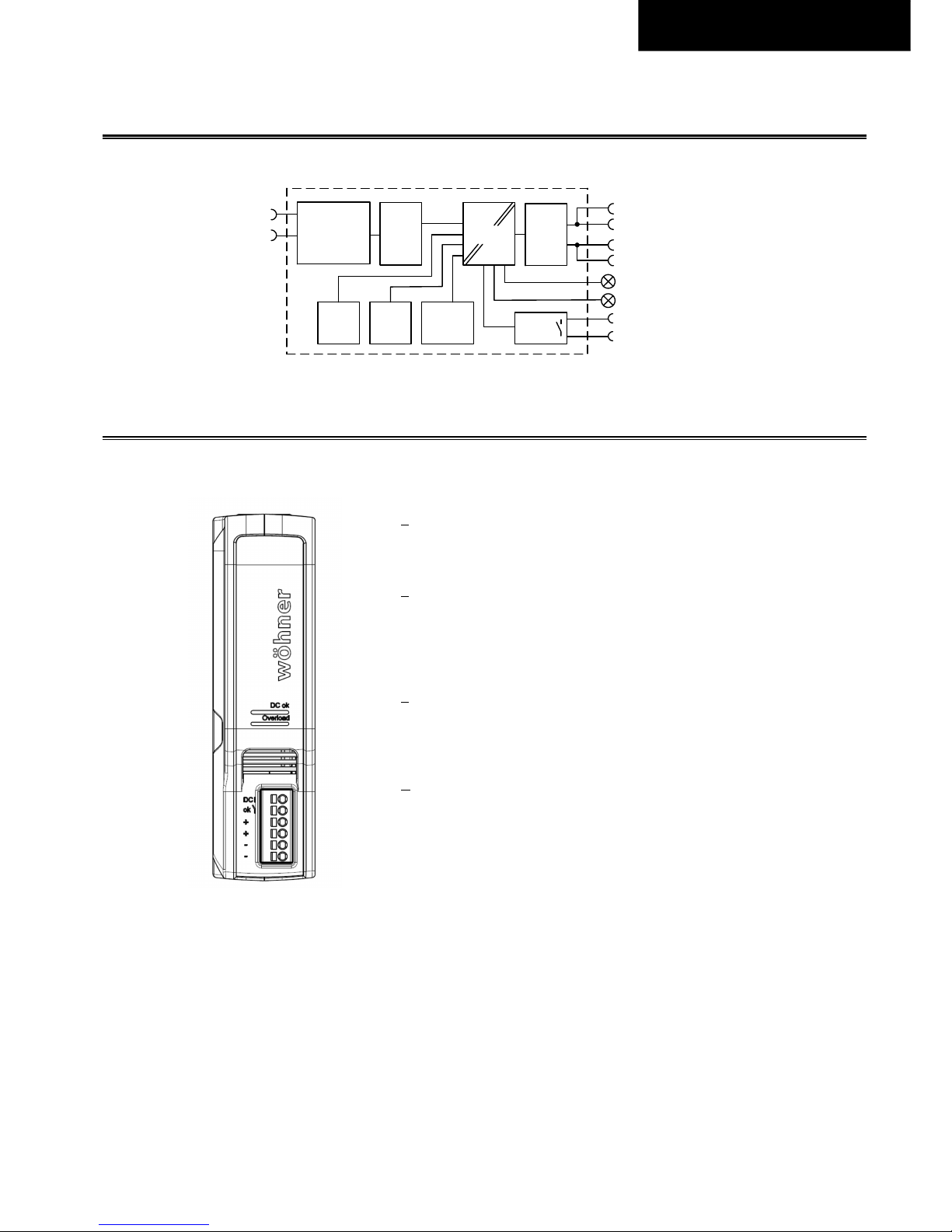
Fig. 12-1
Funktionsdiagramm
13. F
RONTANSICHT UND BEDIENELEMENTE
Fig. 13-1
Fronatansicht
A DC-OK LED
Die LED leuchtet, wenn die Ausgangsspannung im Betrieb über 20V
liegt.
B Overload LED
Die LED leuchtet, wenn die Ausgangsspannung unter 19 V fällt oder
wenn ein Kurzschluss am Ausgang auftritt. Die LED blinkt, wenn das
Gerät aufgrund von Übertemperatur ausgeschaltet wurde. Die
Eingangsspannung muss dafür anliegen.
C Output Terminals
(Push-in Klemmen)
(Zwei identische + Pole und zwei identische - Pole)
+
Positiver Ausgang
– Negativer Ausgang
D DC-OK Relay Kontakt
(Push-in Klemmen)
Überwacht die Ausgangsspannung, siehe Kapitel 7 für Details.
+
+
-
-
Output
Over-
Volt age
Protection
PFC
Converter
Power
Converter
Output
Filter
Output
Power
Manager
Temper-
ature
Shutdown
Input Fuse
Input Filter
Input Rectif ier
Inrush Current
Limiter
L1
DC-OK
Contact
DC-OK
LED
DC-ok
Relay
L2
Overload
LED
Page 13
Revision 1, Stand Nov. 2017 13
Deutsch.
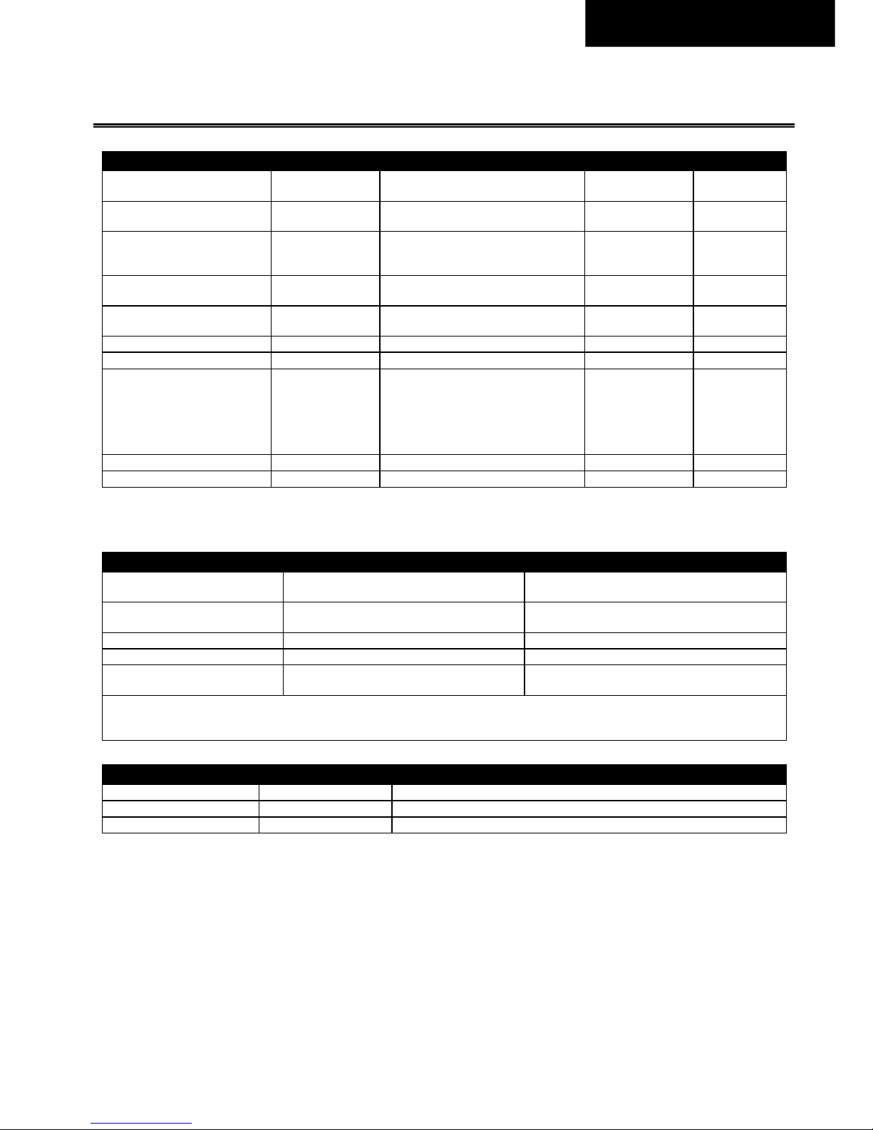
14. EMV
EMC Störfestigkeit Fachgrundnorm: EN 61204-3
Elektrostatische Entladung EN 61000-4-2
Contact discharge
Air discharge
8kV
8kV
Kriterium A
Kriterium A
Hochfrequentes
elektromagnetisches Feld
EN 61000-4-3 80MHz - 6GHz T.b.d. Kriterium A
Schnelle Transienten (Burst) EN 61000-4-4
Eingangsleitungen
Ausgangsleitungen
DC-OK Signal (Kupplungsklemme)
4kV
2kV
2kV
Kriterium A
Kriterium A
Kriterium A
Stoßspannung am Eingang EN 61000-4-5 T.b.d.
2kV
4kV
Kriterium A
Kriterium A
Stoßspannung am Ausgang EN 61000-4-5 T.b.d.
1kV
2kV
Kriterium A
Kriterium A
Stoßspannung an Signalen EN 61000-4-5 T.b.d. 1kV Kriterium A
Leitungsgeführte Störgrößen EN 61000-4-6 0.15-80MHz T.b.d. Kriterium A
Netzspannungseinbrüche EN 61000-4-11
0% von 380Vac
40% von 380Vac
70% von 380Vac
0% von 480Vac
40% von 480Vac
70% von 480Vac
0Vac, 20ms
152Vac, 200ms
266Vac, 500ms
0Vac, 20ms
192Vac, 200ms
336Vac, 500ms
Kriterium A
Kriterium B
Kriterium B
Kriterium A
Kriterium B
Kriterium A
Spannungsunterbrechungen EN 61000-4-11 0% von 380Vac (=0V) 5000ms Kriterium B
Starke Transienten VDE 0160 Über den gesamten Lastbereich 1584V, 1,3ms Kriterium A
Kriterien:
A:
Die Stromversorgung weist ein normales Betriebsverhalten innerhalb der definierten Grenzen auf.
B:
Vorübergehender Funktions- oder Leistungsverlust während der Tests – schaltet sich gegebenenfalls ab und eigenständig wieder ein.
EMV-Störaussendung Fachgrundnorm: EN 61204-3
Conducted emission
input lines
EN 55011, EN 55015, EN 55022, FCC Teil 15,
CISPR 11, CISPR 22
Klasse A
Conducted emission
output lines 2)
IEC/CISPR 16-1-2, IEC/CISPR 16-2-1 Not required, not considered to be a DC-mains
Störstrahlung EN 55011, EN 55022 Klasse A
Oberschwingungseingangsstrom EN 61000-3-2 Klasse A erfüllt
Spannungsschwankungen, Flicker EN 61000-3-3
Erfüllt, getestet mit konstanter Strombelastung,
nicht pulsierend
Dieses Gerät erfüllt die Forderungen nach FCC Part 15.
Der Betrieb unterliegt den folgenden zwei Bedingungen: (1) Dieses Gerät darf keine schädlichen Störungen verursachen, und (2) dieses Gerät
muss jede empfangene Störung tolerieren, auch Störungen, die zu einem unerwünschten Betrieb führen können
Schaltfrequenzen
PFC Wandler 25-120kHz Abhängig von der Eingangsspannung
Hauptwandler 100 bis 130kHz Abhängig von der Last am Ausgang
Hilfswandler 30kHz Feste Frequenz
Page 14
Revision 1, Stand Nov. 2017 14
Deutsch.
15. U
MGEBUNG
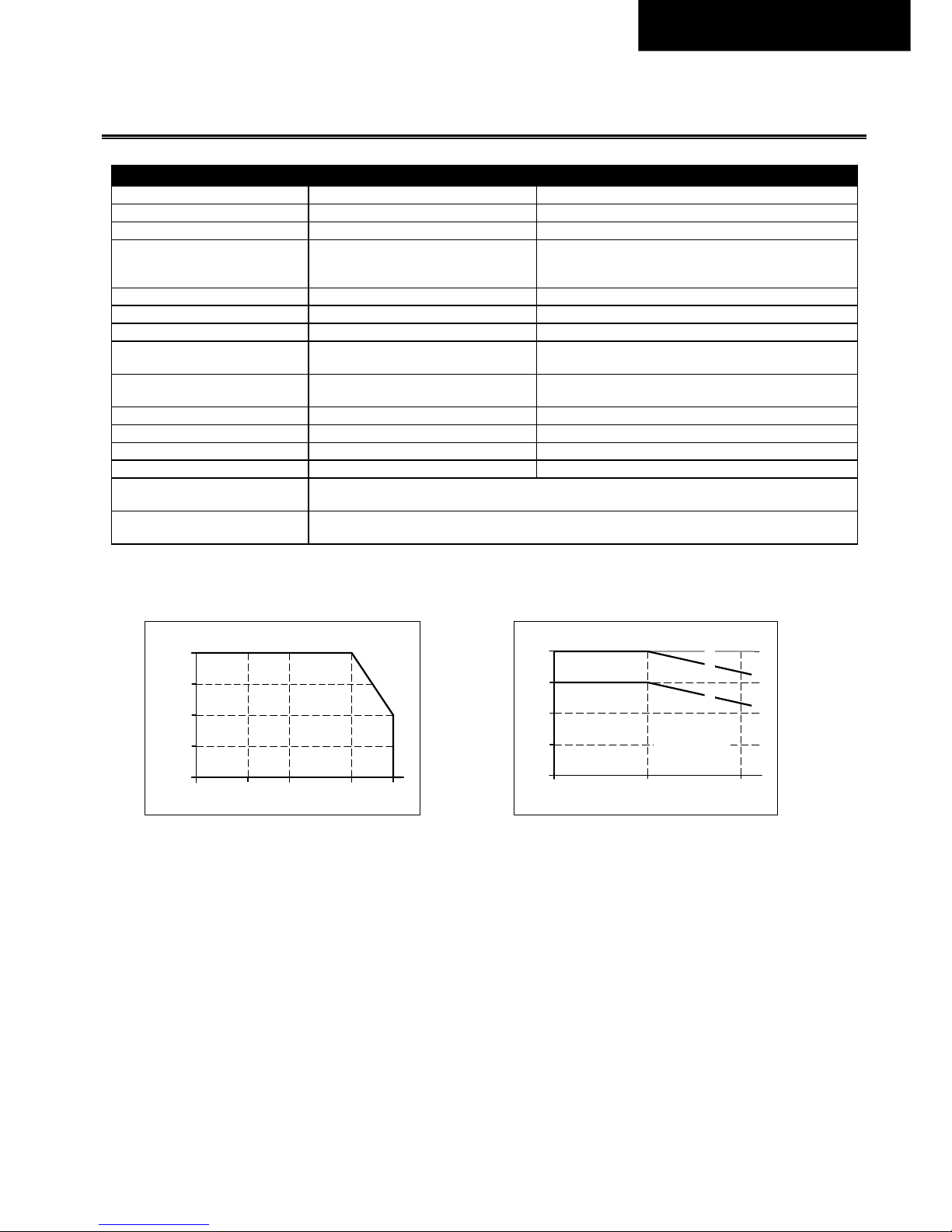
Arbeitstemperatur 1) -25°C bis +70°C (-13°F bis 158°F) Verringerung der Ausgangsleistung gemäß Fig. 15-1
Lagertemperatur -40°C bis +85°C (-40°F bis 185°F) Für Lagerung und Transport
Ausgangsleistungsrücknahme 6W/°C Zwischen +50°C und +70°C (122°F bis 158°F)
Feuchte 5 bis 95% r.F.
IEC 60068-2-30
Nicht unter Spannung setzen, wenn Betauung vorhanden
ist
Schwingen, sinusförmig 2) T.b.d. IEC 60068-2-6
Schocken 2) T.b.d. IEC 60068-2-27
Aufstellhöhe 0 bis 2000m (0 bis 6 560Fuß) Ohne Einschränkungen
2000 bis 4000m (6 560 bis 13 120Fuß)
Ausgangsleistung oder Umgebungstemperatur verringern,
siehe Fig. 15-2.
Leistungsrücknahme wegen
Aufstellhöhe
15W/1000m oder 5°C/1000m Oberhalb von 2000m (6500Fuß), siehe Fig. 15-2
Überspannungskategorie T.b.d. IEC 62477-1, Aufstellhöhen bis 2000m
T.b.d. IEC 60950-1 Aufstellhöhen von 2000m bis 4000m
T.b.d. IEC 62477-1 Aufstellhöhen von 2000m bis 4000m
Verschmutzungsgrad 2 IEC 62477-1, nicht leitend
LABS Kompatibilität
Das Gerät setzt kein Silikon oder andere LABS-kritische Substanzen frei und ist für den Einsatz in
Lackierereien geeignet.
Hörbare Geräusche
Während des Leerlaufs, der Überlast oder des Kurzschlusses können hörbare Geräusche vom Netzteil
ausgehen.
1) Die Arbeitstemperatur ist identisch mit der Umgebungstemperatur und ist definiert als die Lufttemperatur 2cm unterhalb des Geräts.
2) Getestet, wenn das Gerät auf dem CrossBoard montiert ist.
Fig. 15-1
Ausgangsstrom zu Umgebungstemperatur
Fig. 15-2
Ausgangsstrom zu Aufstellhöhe
0
0 +20 +50
+70°C
2.5A
5.0A
7.5A
10A
Allowable Output Current
Ambient Temperature
-25
0
0
2000m
4000m
2.5A
5A
10A
7.5A
Allowed Output Current
Altitude
B
C
A
...
Tamb <
6
0°C
B...
T
amb < 5
0°C
C...
S
hort te
r
m
A
Page 15
Revision 1, Stand Nov. 2017 15
Deutsch.
16. S
ICHERHEITSMERKMALE UND SCHUTZFUNKTIONEN
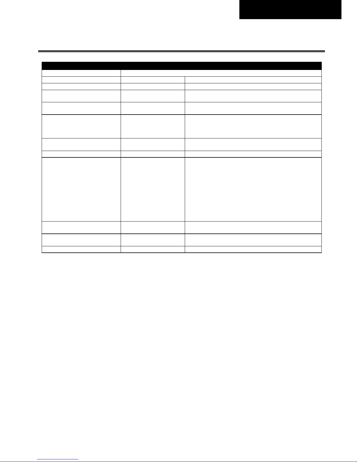
Trennung Eingang/Ausgang Doppelte oder verstärkte galvanische Trennung
SELV IEC/EN 60950-1
PELV IEC/EN 60204-1, EN 62477-1, IEC 60364-4-41
Isolationswiderstand > 500MOhm
Im Auslieferungszustand zwischen Eingang und Ausgang,
gemessen mit 500Vdc
> 500MOhm
Im Auslieferungszustand zwischen Ausgang und DC-OK-Kontakten,
gemessen mit 500 Vdc
Überspannungsschutz am Ausgang
Typ. 30.5Vdc
Max. 32Vdc
Bei einem internen Fehler in der Stromversorgung begrenzt eine
redundante Schaltung die maximale Ausgangsspannung. Der
Ausgang schaltet sich ab und versucht automatisch, sich wieder
einzuschalten.
Schutzklasse II
IEC 61140
Eine PE-Verbindung ist nicht erforderlich
Schutzart IP 30 EN/IEC 60529
Übertemperaturschutz ja Ausgangsabschaltung mit automatischem Neustart.
Der Temperatursensor ist an kritischen Komponenten in der Einheit
installiert und schaltet das Gerät in sicherheitskritischen
Situationen aus, was beispielsweise passieren kann, wenn die
Anforderungen für die Leistungsreduzierung nicht eingehalten
werden, die Umgebungstemperatur zu hoch ist, die Belüftung
gestört ist oder die Anforderungen für die Leistungsreduzierung bei
abweichender Einbaulage nicht eingehalten wurden. Es gibt keine
Korrelation zwischen der Betriebstemperatur und der
Ausschalttemperatur, da dies von Eingangsspannung, Last und
Installationsmethoden abhängt.
Absicherung gegen
Eingangstransienten
MOV
(Metal Oxide Varistor)
Schutzwerte siehe Kapitel 14 (EMV).
Interne Eingangssicherung inbegriffen
Nicht durch den Benutzer austauschbare, träge Sicherung mit
hohem Ausschaltvermögen
Ableitstrom (Leckstrom) Max. 0.25mA
Page 16
Revision 1, Stand Nov. 2017 16
Deutsch.
17. S
PANNUNGSFESTIGKEIT
Die Ausgangsspannung ist potentialfrei und hat keine ohmsche Verbindung zur Erde. Typ- und Stückprüfungen werden vom
Hersteller durchgeführt. Feldprüfungen können im Feld mithilfe geeigneter Prüfgeräte durchgeführt werden, die die Spannung
mit einer langsamen Rampe hochfahren (2s ansteigend und 2s abfallend). Verbinden Sie alle Phasenklemmen und alle
Ausgangspole miteinander, bevor Sie die Prüfungen durchführen. Wenn Sie prüfen, setzen Sie die Einstellung für den
Abschaltstrom auf den Wert in der Tabelle unten.
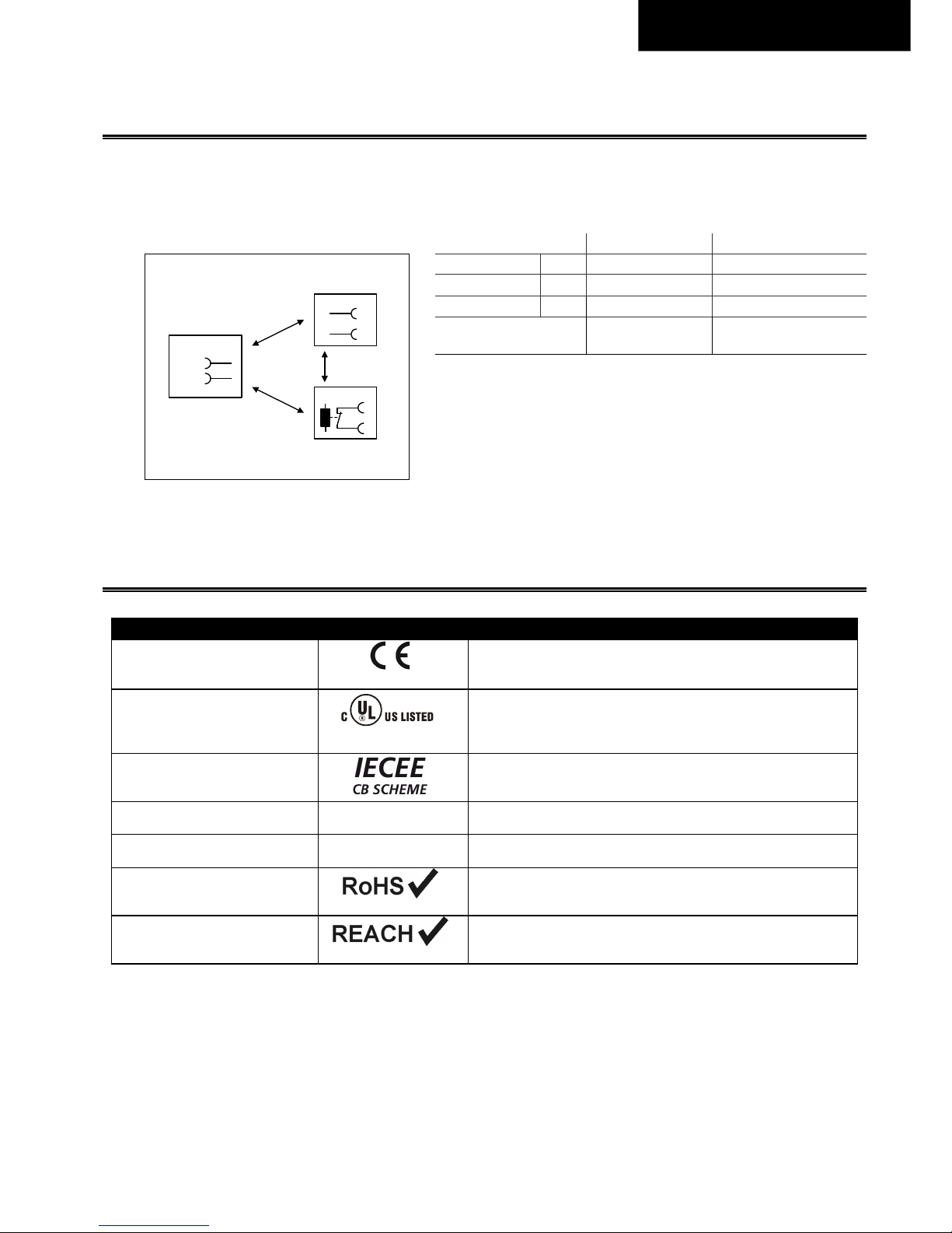
Fig. 17-1
Durchschlagfestigkeit
A B
Typprüfung 60s 3400Vac 500Vac
Stückprüfung 5s 2500Vac 500Vac
Feldprüfung 5s 2000Vac 500Vac
Einstellung des
Abschaltstromes
> 2mA > 1mA
Um die PELV-Anforderungen gemäß EN 60204-1 § 6.4.1 zu erfüllen,
empfehlen wir, entweder den Pluspol, den Minuspol oder einen anderen
Teil des Ausgangskreises mit dem Schutzleitersystem zu verbinden.
Dadurch sollen Situationen vermieden werden, in denen die Last
unerwartet startet oder nicht abgeschaltet werden kann, wenn ein
unbemerkter Erdschluss auftritt.
A*) Achten Sie beim Prüfen des Eingangs gegen DC-OK darauf, dass die maximale Spannung zwischen DC-OK und dem Ausgang nicht überschritten wird
(Spalte D). Wir empfehlen, die DC-OK-Pins und die Ausgangspins bei der Durchführung des Tests miteinander zu verbinden.
18. Z
ULASSUNGEN
EG-Konformitätserklärung
Das CE-Zeichen zeigt die Übereinstimmung mit der
- EMV-Richtlinie und der
- Niederspannungsrichtlinie
UL 61010-2-201
geplant
Sicherheitsanforderungen für elektrische Geräte für Mess-, Steuer- und
Laboranwendungen Teil 2-201: Besondere Anforderungen für
Steuergeräte;
Gelistetes Produkt E-File: T.b.d.
IEC 61010-2-201
geplant
CB-SCHEME Sicherheitsanforderungen für elektrische Geräte zur
Messung, Steuerung und Laboranwendung Teil 2-201: Besondere
Anforderungen für Steuergeräte
IEC 62477-1
T.b.d.
Sicherheitsanforderungen für leistungselektronische Konvertersysteme
und –geräte T.b.d.
IEC/EN 61558-2-16
(Anhang BB)
Sicherheitstransformator
Sicherheits-Trenntransformatoren entsprechend Teil 2-6 der IEC / EN
61558
RoHS Richtlinie
Richtlinie 2011/65 / EU des Europäischen Parlaments und des Rates vom
8. Juni 2011 zur Beschränkung der Verwendung bestimmter gefährlicher
Stoffe in Elektro- und Elektronikgeräten.
REACH Richtlinie
Richtlinie 1907/2006 / EU des Europäischen Parlaments und des Rates
vom 1. Juni 2007 über die Registrierung, Bewertung, Zulassung und
Beschränkung chemischer Stoffe (REACH)
B
A
A
*
)
L1
Input
DC-ok
Output
+
-
L2
IND. CONT. EQ.
Page 17
Revision 1, Stand Nov. 2017 17
Deutsch.
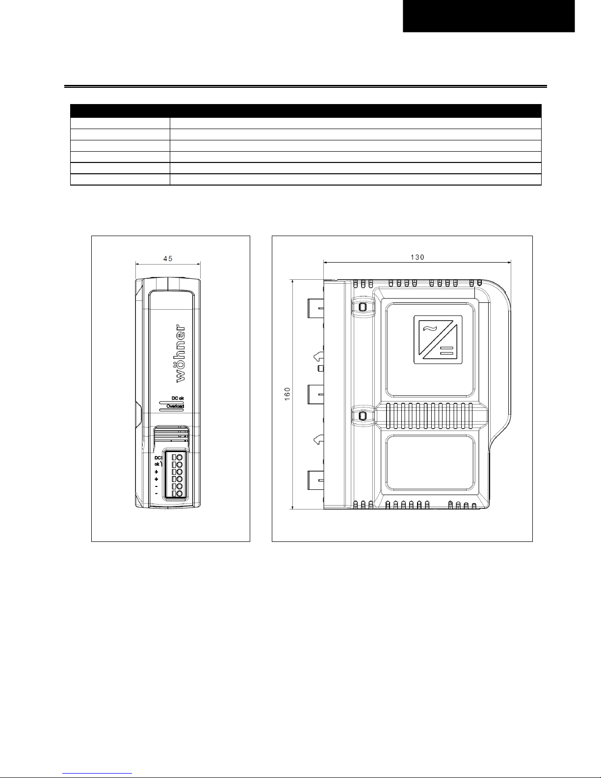
19. A
BMESSUNGEN UND GEWICHT
Breite 45mm 1.77’’
Höhe 160mm 6.3’’
Tiefe 130mm 5.12’’
Gewicht 550g / 1.21lb
Gehäusematerial T.b.d.
Einbauabstände Siehe Kapitel 2
Fig. 19-1
Frontansicht
Fig. 19-2
Seitenansicht
Alle Abmessungen in mm
Page 18
Revision 1, Stand Nov. 2017 18
Deutsch.
20. A
NWENDUNGSHINWEISE
20.1. I
NDUKTIVE UND KAPAZITIVE LASTEN
Lasten wie Bremsmotoren und Induktivitäten können Spannung an die Stromversorgung zurückspeisen. Diese Eigenschaft wird
auch als Rückspannungsfestigkeit oder Widerstand gegen Rück-E.M.F. (Electro Magnetic Force) genannt.
Diese Stromversorgung ist resistent und zeigt keine Fehlfunktion, wenn eine Last Spannung an die Stromversorgung
zurückspeist. Es spielt keine Rolle, ob die Stromversorgung ein- oder ausgeschaltet ist.
Die maximal zulässige Rückkopplungsspannung beträgt 35 Vdc. Die absorbierende Energie kann entsprechend dem eingebauten
groß dimensionierten Ausgangskondensator berechnet werden, der in Kapitel 5 spezifiziert ist.
20.2. S
ERIENSCHALTUNG
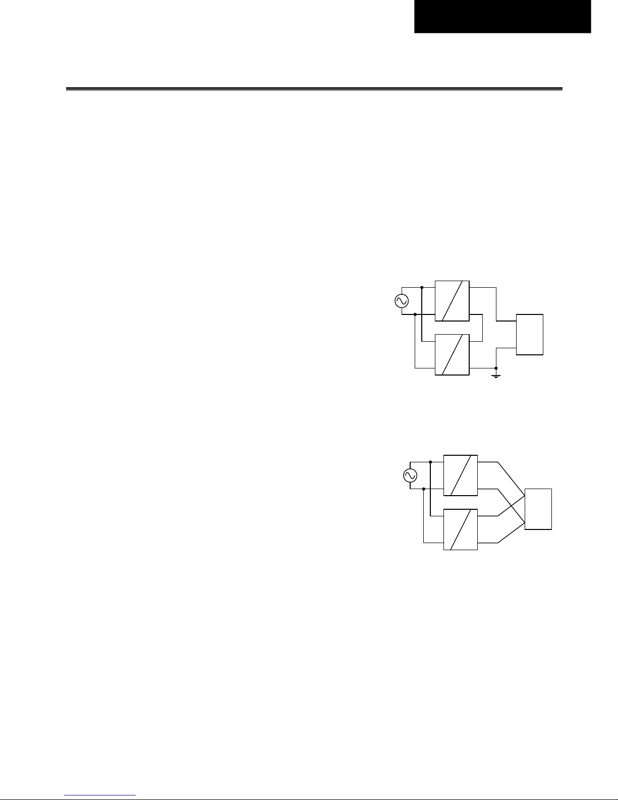
Bis zu drei Netzteile können für höhere Ausgangsspannungen in Reihe geschaltet
werden.
Bitte beachten Sie: Spannungen mit einem Potential über 60Vdc zählen nicht mehr
zu SELV und können gefährlich sein. Solche Spannungen müssen berührungssicher
installiert werden. Erdung des Ausgangs ist erforderlich, wenn die Summe der
Ausgangsspannung über 60 VDC liegt.
Vermeiden Sie Rückspannungen (z. B. von einem Bremsmotor oder einer Batterie),
die an die Ausgangsklemmen angelegt wird.
Achten Sie darauf, dass Ableitstrom, EMB, Einschaltstrom und Oberschwingungen
bei Verwendung mehrerer Netzteile zunehmen.
20.3. P
ARALLELBETRIEB ZUR LEISTUNGSERHÖHUNG
Eine Parallelschaltung von Stromversorgungen für höhere Ausgangsleistung ist für
Umgebungstemperaturen bis + 45 ° C zulässig.
Das Gerät verfügt über eine "Soft-Output-Regelcharakteristik" (Parallel Use Mode),
um eine Stromaufteilung zwischen mehreren Geräten zu erreichen, wenn diese
parallel geschaltet sind. Die "Soft-Output-Regelcharakteristik" regelt die
Ausgangsspannung so, dass die Spannung im Leerlauf ca. 4% höher als bei 10A Last
(siehe Kapitel 5).
Wenn mehr als drei Einheiten parallel geschaltet sind, ist an jedem Ausgang eine
Sicherung oder ein Leistungsschalter mit einem Nennstrom von 15 A oder 16 A erforderlich. Alternativ kann auch eine Diode oder
ein Redundanzmodul verwendet werden.
Schalten Sie alle Einheiten gleichzeitig ein, um den Überlastungsmodus HiccupPLUS zu vermeiden. Es kann auch erforderlich sein,
die Eingangsleistung zu schalten (Ausschalten für mindestens fünf Sekunden), wenn der Ausgang aufgrund von Überlast oder
Kurzschluss im HiccupPLUS-Modus war und der erforderliche Ausgangsstrom höher als der Strom einer Einheit ist.
Achten Sie darauf, dass Ableitstrom, EMB, Einschaltstrom und Oberschwingungen bei Verwendung mehrerer Netzteile
zunehmen.
Unit A
AC
DC
Unit B
AC
DC
-
+
-
+
Load
+
-
Unit A
AC
DC
Unit B
AC
DC
-
+
-
+
Load
+
-
Earth
(see notes)
Page 19
Revision 1, status Nov. 2017 19
English.
G
ENERAL DESCRIPTION
BROOME10 is an industrial grade power supply for 3-Phase mains systems designed for use on the Crossboard connection system
from company Wöhner.
It provides a floating, stabilized and galvanically separated SELV/PELV output voltage.
The most outstanding features of BROOME10 are the high efficiency, the high immunity to transients and power surges, the
advanced inrush current limitation, the active PFC and the wide operational temperature range.
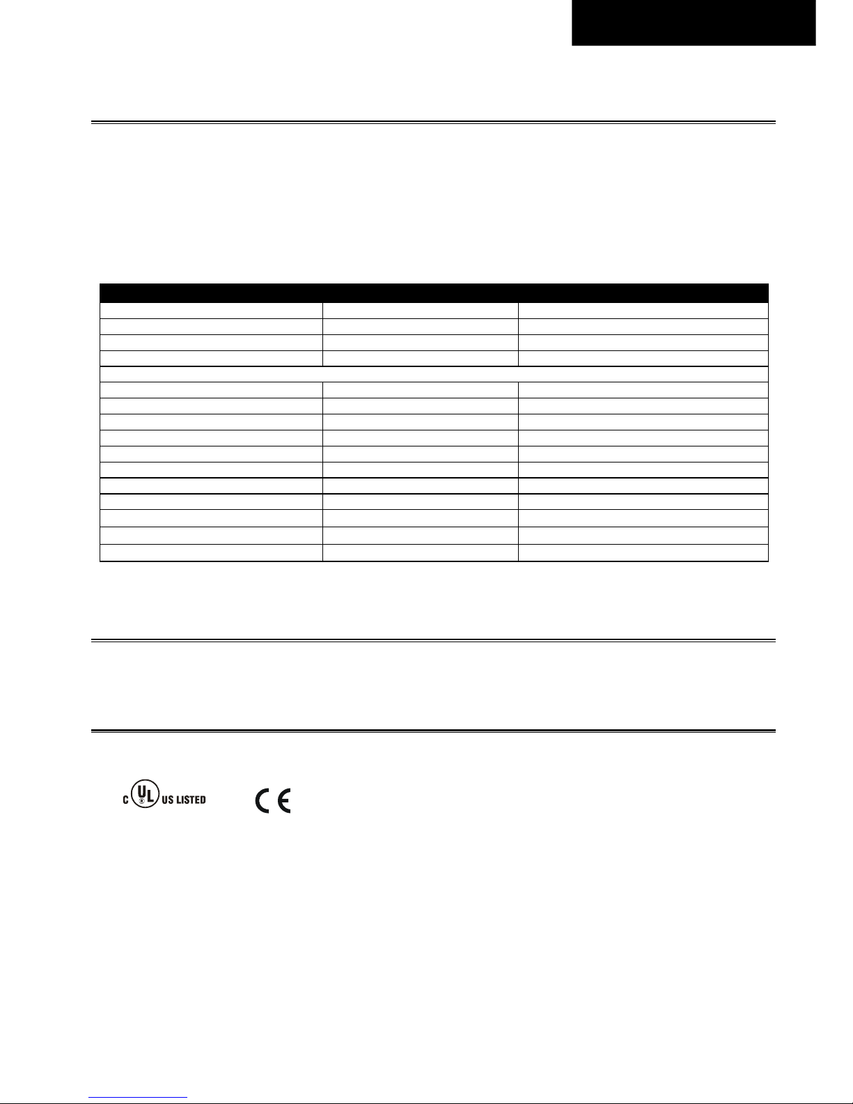
Technical Data
Output voltage DC 24V 0/+6% over entire load range
Adjustment range -
Output current 10A Below +50°C ambient
5A At +70°C ambient
Derate linearely between +50°C and +70°C
Input voltage AC AC 380-480V -10%/ +15%
Mains frequency 50-60Hz ±6%
Input current AC 0.77 / 0.62A At 400 / 480Vac
Power factor 0.70 / 0.73 At 400 / 480Vac
Input inrush current 1.5 / 1.5Apk At 400 / 480Vac
Efficiency 94.9 / 94.8% At 400 / 480Vac
Losses 12.8 / 13.2W At 400 / 480Vac
Hold-up time 20 / 20ms At 400 / 480Vac
Temperature range -25°C to +70°C
Size (w x h x d) 45x160x130mm
Weight 550g / 1.21lb
O
RDER NUMBERS
BROOME10 CrossBoard®
36200
M
ARKINGS
For details and a complete approval list see section 18.
UL 61010-2-201
IND. CONT. EQ.
Page 20

Revision 1, status Nov. 2017 20
English.
I
NDEX
The information given in this document is correct to the best of our knowledge and experience at the time of publication. If not
expressly agreed otherwise, this information does not represent a warranty in the legal sense of the word. As the state of our
knowledge and experience is constantly changing, the information in this data sheet is subject to revision. We therefore kindly
ask you to always use the latest issue of this document (consult PULS).
No part of this document may be reproduced or utilized in any form without our prior permission in writing.
T
ERMINOLOGY AND ABREVIATIONS
PE and symbol
PE is the abbreviation for Protective Earth and has the same meaning as the symbol .
Earth, Ground
This document uses the term “earth” which is the same as the U.S. term “ground”.
T.b.d.
To be defined, value or description will follow later.
AC 400V
A figure displayed with the AC or DC before the value represents a nominal voltage with standard
tolerances (usually ±15%) included.
E.g.: DC 12V describes a 12V battery disregarding whether it is full (13.7V) or flat (10V)
400Vac
A figure with the unit (Vac) at the end is a momentary figure without any additional tolerances
included.
50Hz vs. 60Hz
As long as not otherwise stated, AC 400V parameters are valid at 50Hz mains frequency. AC 480V
parameters are valid for 60Hz mains frequency.
may
A key word indicating flexibility of choice with no implied preference.
shall
A key word indicating a mandatory requirement.
should
A key word indicating flexibility of choice with a strongly preferred implementation.
Page 21

Revision 1, status Nov. 2017 21
English.
1. I
NTENDED USE
This device is designed for installation in an enclosure and is intended for general use such as in industrial control, office,
communication, and instrumentation equipment.
Do not use this device in equipment, where malfunction may cause severe personal injury or threaten human life.
2. I
NSTALLATION REQUIREMENTS
Risk of electrical shock, fire, personal injury or death.
- Turn power off before working on the device. Protect against inadvertent re-powering.
- Make sure that the wiring is correct by following all local and national codes.
- Do not modify or repair the unit.
- Do not open the unit as high voltages are present inside.
- Use caution to prevent any foreign objects from entering the housing.
- Do not use in wet locations or in areas where moisture or condensation can be expected.
- Do not touch during power-on, and immediately after power-off. Hot surfaces may cause burns.
Obey the following installation requirements:
- Install device in an enclosure providing protection against electrical, mechanical and fire hazards.
- This device may only be installed and put into operation by qualified personnel.
- Do not plug or unplug the device as long as input voltage is present.
- Use the device in a controlled environment. Do not use the device in pollution degree 3 areas without additional protection
or in applications where a degree of protection better than IP30 is required.
- The device is designed for convection cooling and does not require an external fan. Do not obstruct airflow and do not cover
ventilation grid.
- Keep the following minimum installation clearances when the device is permanently loaded with more than 50% of the
nominal current: 40mm on top, 20mm on the bottom, 0mm left and right side.
- Make sure that the wiring is correct by following all local and national codes. Use appropriate copper cables that are
designed for a minimum operating temperature of 60°C for ambient temperatures up to +45°C, 75°C for ambient
temperatures up to +60°C and 90°C for ambient temperatures up to +70°C. Ensure that all strands of a stranded wire enter
the terminal connection.
- This device does not contain serviceable parts. The tripping of an internal fuse is caused by an internal defect. If damage or
malfunction should occur during installation or operation, immediately turn power off and send the device to the factory
for inspection.
- The device is designed, tested and approved for branch circuits up T.b.d. ampacity without additional protection device. If an
external fuse is utilized, do not use circuit breakers smaller than 6A B- or C-Characteristic to avoid a nuisance tripping of the
circuit breaker.
WARNING
Page 22
Revision 1, status Nov. 2017 22
English.
3. AC-I
NPUT
The device is suitable to be supplied from TN-, TT- and IT mains networks with AC voltage. It operates from a three-phase mains
system but is employing only two legs of the three phase system.
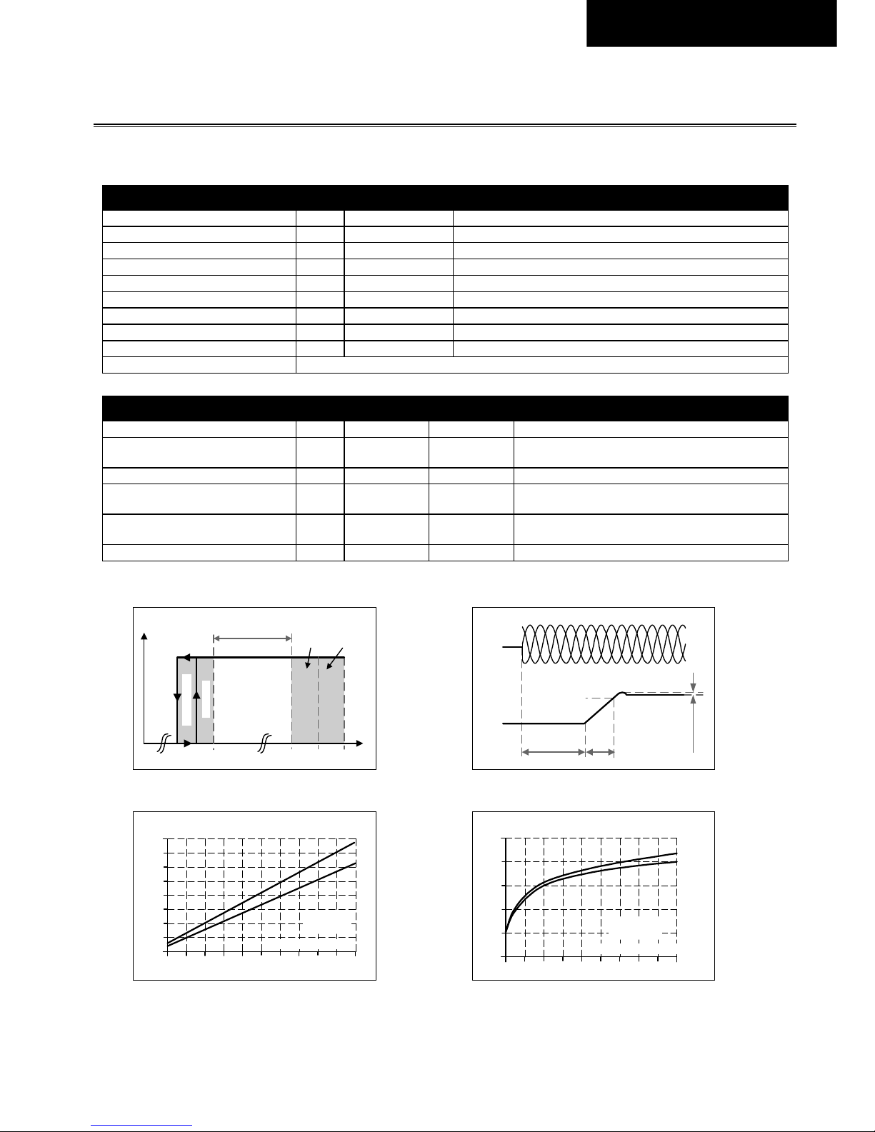
AC input Nom. AC 380-480V -10% / +15%
AC input range Min. 342-552Vac Continuous operation
Overvoltage resistance Min. 630Vac Temporarily allowed
Min. 630-700Vac For maximal 10s (occasional)
Min. 700-800Vac For maximal 500ms (occasional)
Allowed voltage L to earth Max. 552Vac Continuous according to IEC 62477-1
Input frequency Nom. 50–60Hz ±6%
Turn-on voltage Typ. 335Vac Steady-state value, see Fig. 3-1
Shut-down voltage Typ. 325Vac Steady-state value, see Fig. 3-1
External input protection See recommendations in chapter 2.
AC 400V AC 480V
Input current Typ. 0.77A 0.62A At 24V, 10A, see Fig. 3-3
Power factor Typ. 0.70 0.73
At 24V, 10A, see Fig. 3-4
According to DIN 40110-2 for 3-phase systems
Start-up delay Typ. 200ms 200ms See Fig. 3-2
Rise time Typ. 55ms 55ms
At 24V, 10A resistive load, 0mF load capacitance, see
Fig. 3-2
Typ. 90ms 90ms
at 24V, 10A resistive load, 10mF load capacitance, see
Fig. 3-2
Turn-on overshoot Max. 200mV 200mV See Fig. 3-2
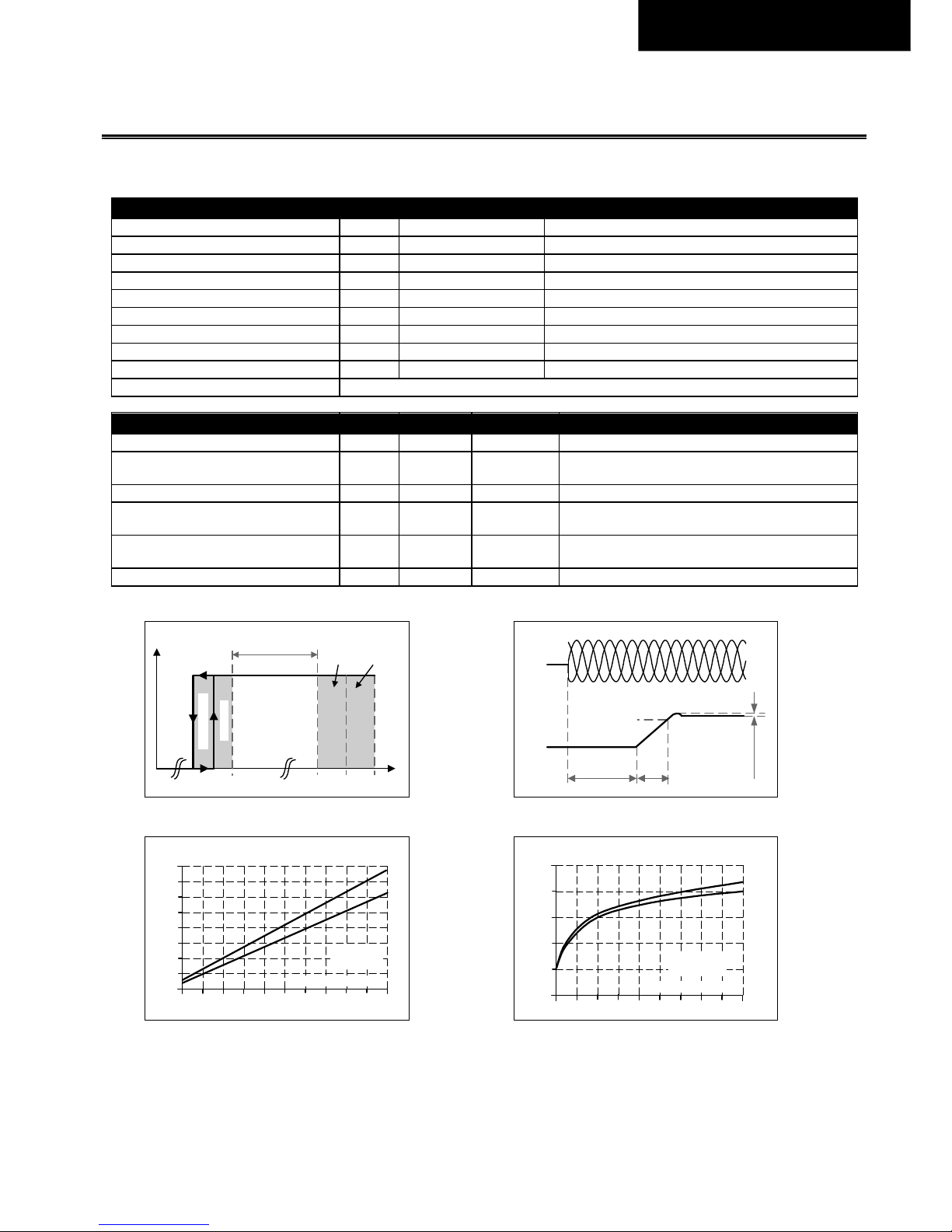
Fig. 3-1
Input voltage range
Fig. 3-2
Turn-on behavior, definitions
Fig. 3-3
Input current vs. output current
Fig. 3-4
Power factor vs. output current
Turn-on
342
Rated
input range
max.
500ms
V
IN
P
OUT
800Vac552
Shu t -dow n
700
max.
10s
Start-up
delay
Rise
Time
Overshoot
- 5%
Output
Voltage
Input
Voltage
L1 L2 L3
1 2 3 4 5 6 7 8 9
0
0.1
0.2
0.4
0.6
0.7
0.8A
Input Current, typ.
10A
Output Current
(a)
(b)
0
0.5
a) 400Vac
b) 480Vac
0.3
Power Factor, typ.
1 2 3 4 5 6 7 8 9 10A
0.3
0.4
0.5
0.6
0.7
0.8
Output Current
(a) 400Vac,
(b) 480Vac
(a)
(b)
Page 23
Revision 1, status Nov. 2017 23
English.
4. I
NPUT INRUSH CURRENT
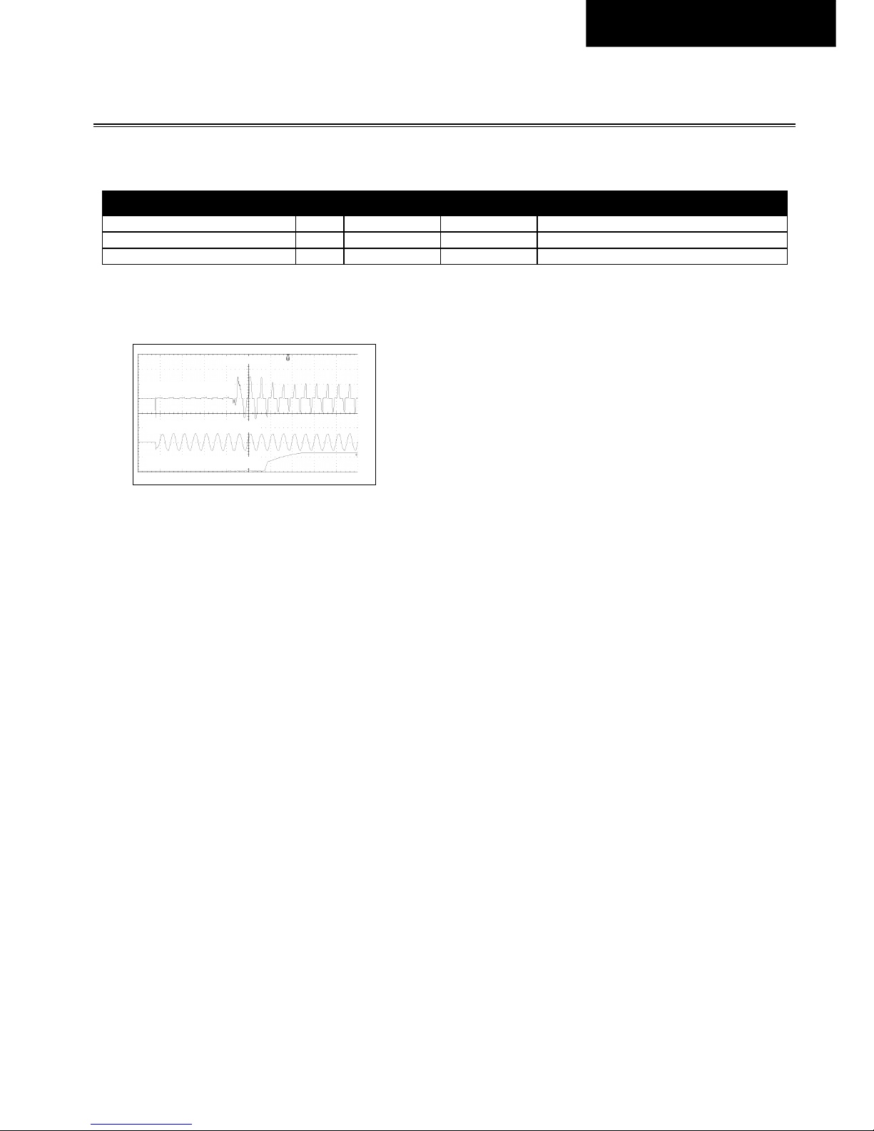
An active inrush limitation circuit limits the input inrush current after turn-on of the input voltage.
The charging current into EMI suppression capacitors is disregarded in the first microseconds after switch-on.
AC 400V AC 480V
Inrush current Max. 2Apeak 2Apeak Temperature independent
Typ. 1.5Apeak 1.5Apeak Temperature independent
Inrush energy Max. 1A²s 1A²s Temperature independent
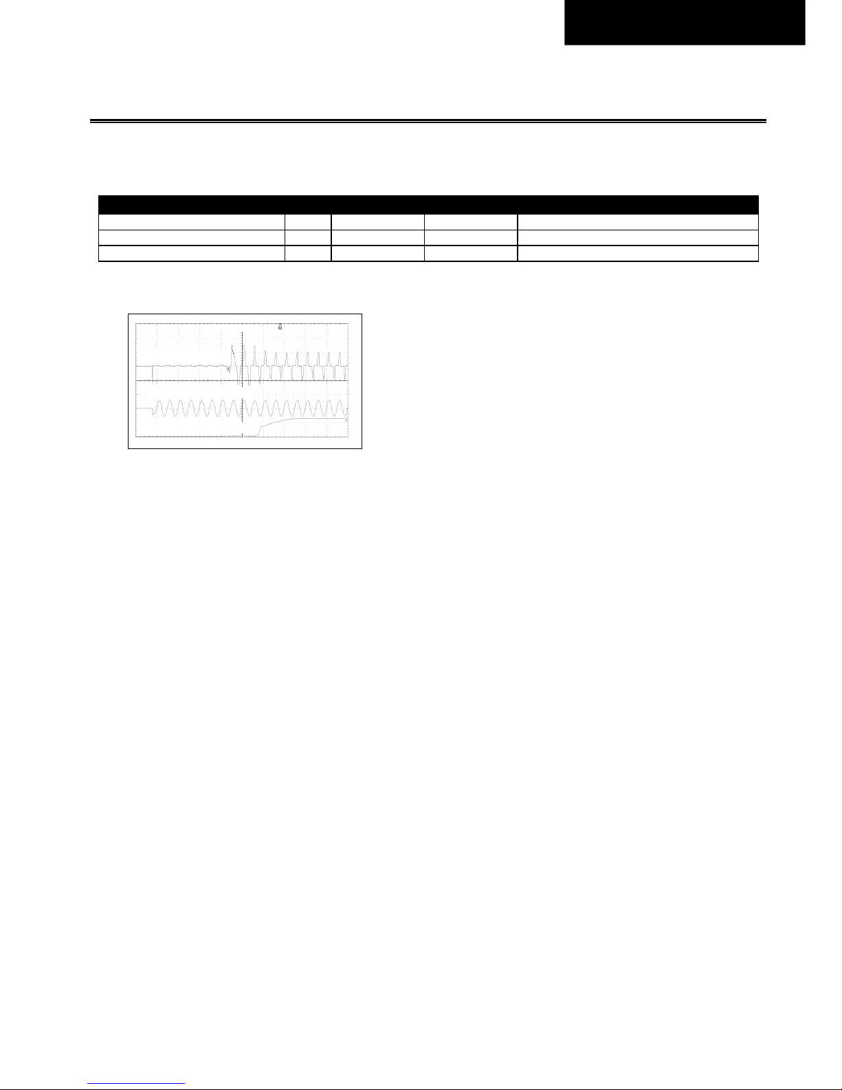
Fig. 4-1
Typical turn-on behaviour at
nominal load, 400Vac input and 25°C
ambient
Input voltage 1kV/DIV
Output voltage 20V/DIV
Input current 1A/DIV
40ms/DIV
Page 24
Revision 1, status Nov. 2017 24
English.
5. O
UTPUT
Output voltage Nom. 24V 0/+6%
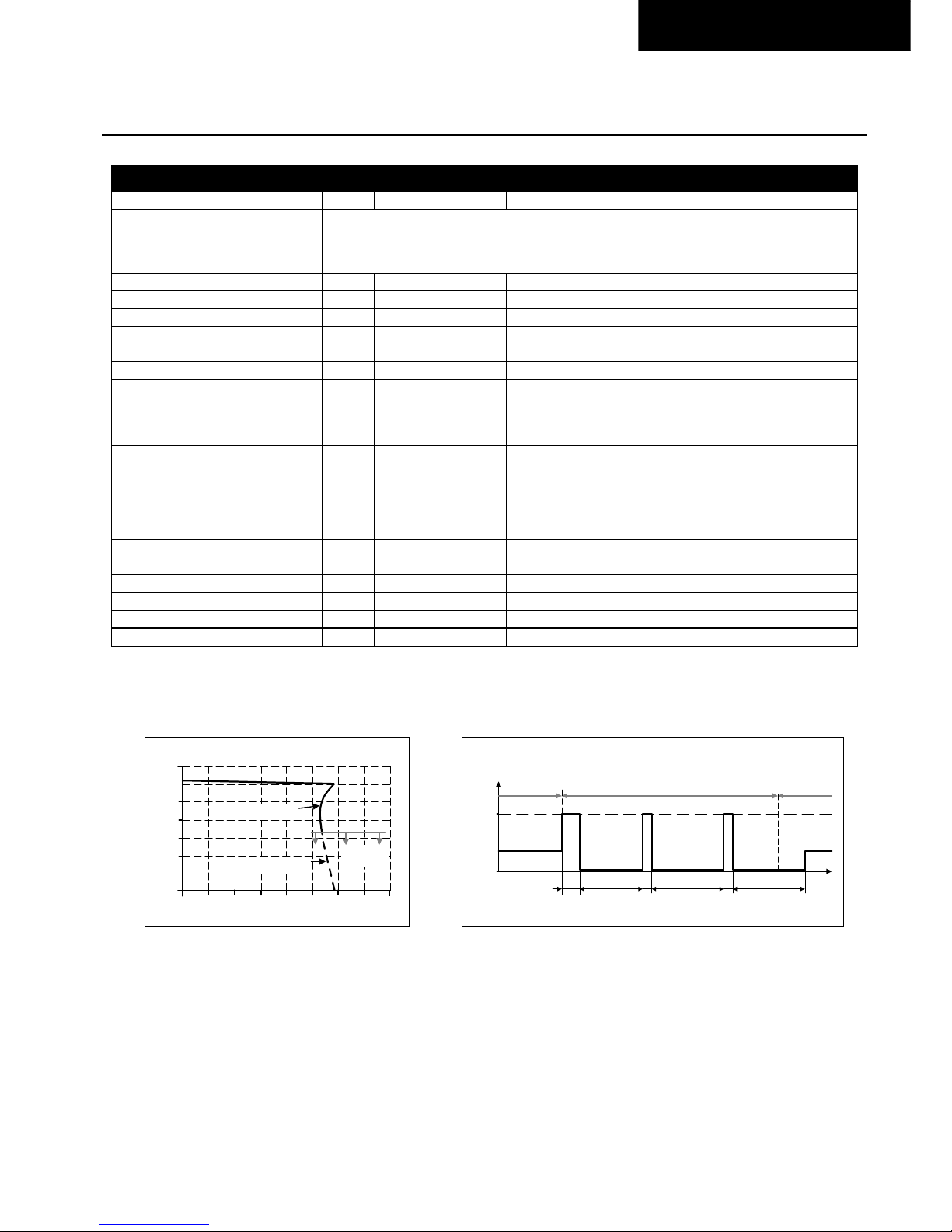
The device is featured with a “soft output regulation characteristic” (Parallel Use Mode) in order to
achieve current share between multiple devices, when they are connected in parallel. The “soft
output regulation characteristic” regulates the output voltage in such a manner, that the voltage at
no load is approx. 4% higher than at 10A load.
Adjustment range - Not adjustable
Line regulation Max. 10mV Between 342 and 552Vac
Load regulation Typ. 1000mV Between 0 and 10A, static value, see Fig. 5-1
Ripple and noise voltage Max. 50mVpp Bandwidth 20Hz to 20MHz, 50Ohm
Output current Nom. 10A At ambient temperatures below +50°C, see Fig. 15-1
Nom. 5A At +70°C ambient temperature, see Fig. 15-1
Overload protection Included
Electronically protected against no-load, overload and short
circuit. In case of a protection event, audible noise may occur. No
external protection needed.
Overload behaviour Continuous current Output voltage above 13Vdc, see Fig. 5-1
HiccupPLUS mode
Output voltage below 13Vdc, see Fig. 5-1 and Fig. 5-2.
The power supply delivers continuous output current for 2.8s.
After this, the output is switched off for 7s before a new start
attempt with 1.2s is automatically performed. This cycle is
repeated as long as the overload exists. If the overload has been
cleared, the device will operate normally.
Short-circuit current Min. 10.4A1) Load impedance <50mOhm
Max. 13A1) Load impedance <50mOhm
Max. 5.0A Average (R.M.S.) current, load impedance <50mOhm
Output capacitance Typ. 4 400µF Included inside the power supply
Capacitive loads Max. 1F Max. 2A additional load during charging
Inductive loads Unlimited
1) Discharge current of output capacitors is not included.
Fig. 5-1
Output voltage vs. output current,
typ.
Fig. 5-2
Short-circuit on output, Hiccup
PLUS
mode, typ.
Output Voltage
0
0 10
4
8
12
28V
16
20
24
16A62 4 8 12 14
Output Current
Hi ccup
PLUS
mode
Intermitted
current
Continuous
current
Output
Current
0
12.5A
7s7s 1.2s2.8s
t
Short -circuit
Normal
operat ion
Normal
operation
1.2s 7s
Page 25
Revision 1, status Nov. 2017 25
English.
6. H
OLD-UP TIME
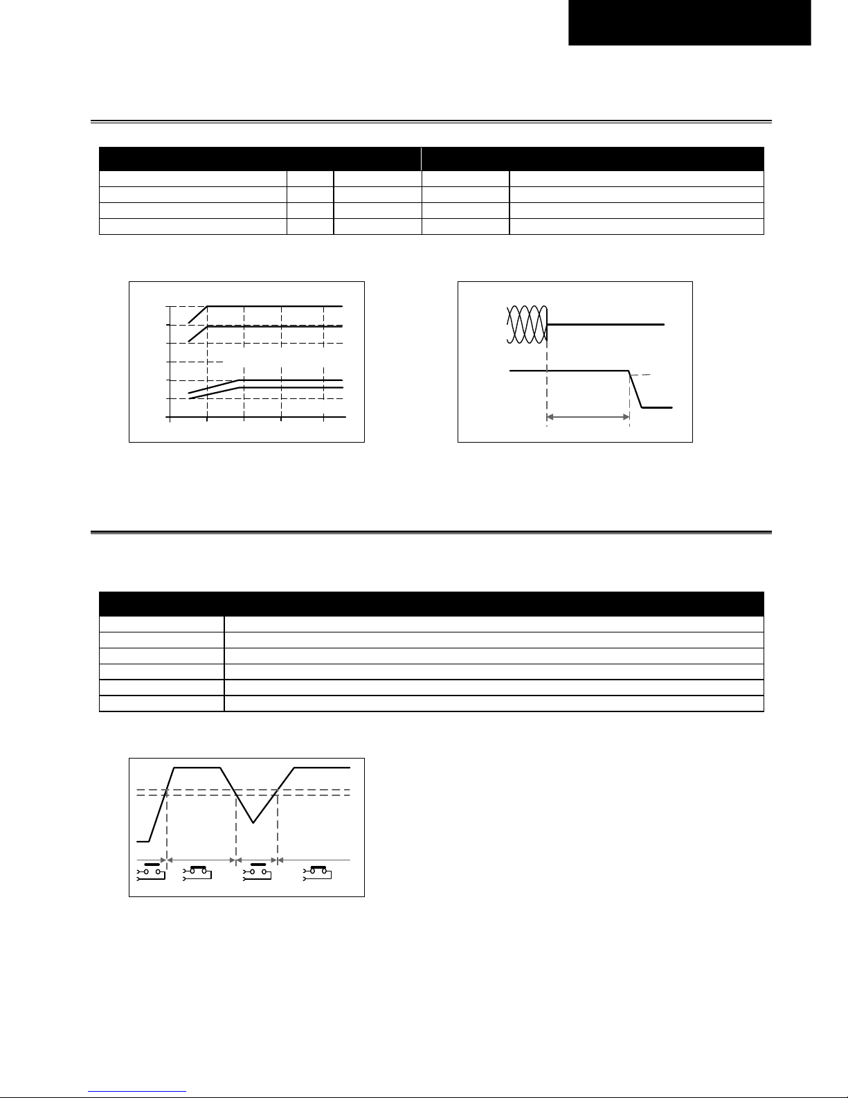
AC 400V AC 480V
Hold-up Time Typ. 60ms 60ms At 5A load current
Min. 49ms 49ms At 5A load current
Typ. 20ms 20ms At 10A load current
Min. 16ms 16ms At 10A load current
Fig. 6-1
Hold-up time vs. input voltage
Fig. 6-2
Shut-down behaviour, definitions
7. DC-OK R
ELAY CONTACT
This feature monitors the output voltage on the output terminals of a running power supply and is independent of back-fed
voltage.
Contact closes As soon as the output voltage reaches typically 20V.
Contact opens As soon as the output voltage falls below typically 19V.
Switching hysteresis 1V
Contact ratings Maximal 60Vdc 0.3A, 30Vdc 1A, 30Vac 0.5A, resistive load
Minimal permissible load: 1mA at 5Vdc
Isolation voltage See dielectric strength table in chapter 17.
Fig. 7-1
DC-ok relay contact behavior
0
10
20
30
60ms
320 360 400 440 480Vac
Input Voltage
40
50
Hold-up Time
a
b
c
d
a) 24V 5A typ.
b) 24V 5A min.
c) 24V 10A typ.
d) 24V 10A min.
- 5%
Hold-up Time
Output
Voltage
Input
Voltage
L1 L2 L3
20V
open openclosed closed
19V
Page 26
Revision 1, status Nov. 2017 26
English.
8. E
FFICIENCY AND POWER LOSSES
AC 400V AC 480V
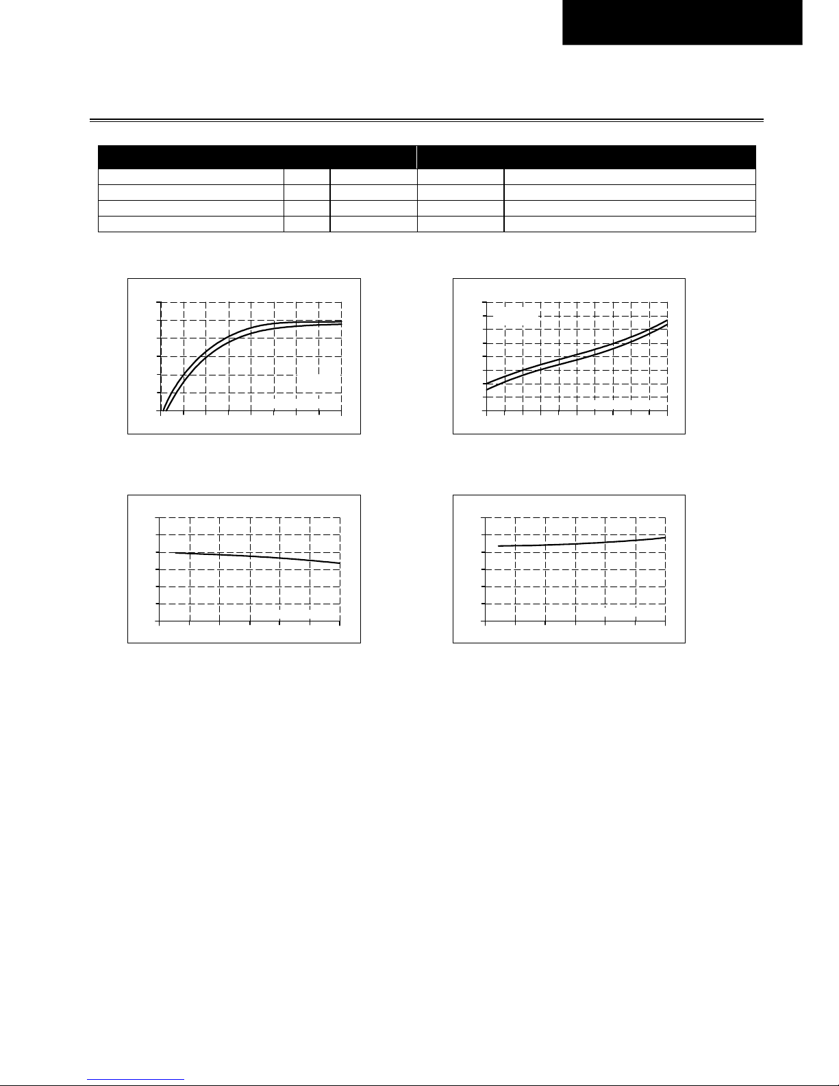
Efficiency Typ. 94.9% 94.8% At 24V, 10A
Power losses Typ. 3.3W 4.0W At 24V, 0A
Typ. 7.6W 8.2W At 24V, 5A
Typ. 12.8W 13.2W At 24V, 10A
Fig. 8-1
Efficiency vs. output current, typ.
Fig. 8-2
Losses vs. output current, typ.
Fig. 8-3
Efficiency vs. input voltage at 10A,
typ.
Fig. 8-4
Losses vs. input voltage at 10A,
typ.
Efficiency
2
92
94
95
90
96%
10A4 7 86
Output Current
953
93
91
(a)
(a) 400Vac
(b) 480Vac
(b)
Power Losses
0 2 4 8 9 10A
0
2
6
8
12
14
16W
4
6107531
Output Current
(a)
(
b
)
(a) 400Vac
(b) 480Vac
Efficiency
320 360 400 440 480
96%
93.5
94.5
95.5
95.0
94.0
93.0
520
560Vac
Input Voltage
Power Losses
320 360 400 440 480
16W
6
10
14
12
8
4
520
560Vac
Input Voltage
Page 27
Revision 1, status Nov. 2017 27
English.
9. L
IFETIME EXPECTANCY
The Lifetime expectancy shown in the table indicates the minimum operating hours (service life) and is determined by the
lifetime expectancy of the built-in electrolytic capacitors. Lifetime expectancy is specified in operational hours and is calculated
according to the capacitor’s manufacturer specification. The manufacturer of the electrolytic capacitors only guarantees a
maximum life of up to 15 years (131 400h). Any number exceeding this value is a calculated theoretical lifetime which can be
used to compare devices.
AC 400V AC 480V
Lifetime expectancy T.b.d. T.b.d. At 5A and 25°C
T.b.d. T.b.d. At 10A and 25°C
T.b.d. T.b.d. At 5A and 40°C
53 000h T.b.d. At 10A and 40°C
10. MTBF
MTBF stands for Mean Time Between Failure, which is calculated according to statistical device failures, and indicates reliability
of a device. It is the statistical representation of the likelihood of a unit to fail and does not necessarily represent the life of a
product.
The MTBF figure is a statistical representation of the likelihood of a device to fail. A MTBF figure of e.g. 1 000 000h means that
statistically one unit will fail every 100 hours if 10 000 units are installed in the field. However, it can not be determined if the
failed unit has been running for 50 000h or only for 100h.
For these types of units the MTTF (Mean Time To Failure) value is the same value as the MTBF value.
AC 400V AC 480V
MTBF SN 29500, IEC 61709 T.b.d. T.b.d. At 10A and 40°C
T.b.d. T.b.d. At 10A and 25°C
MTBF MIL HDBK 217F T.b.d. T.b.d. At 10A and 40°C; Ground Benign GB40
T.b.d. T.b.d. At 10A and 25°C; Ground Benign GB25
T.b.d. T.b.d. At 10A and 40°C; Ground Fixed GF40
T.b.d. T.b.d. At 10A and 25°C; Ground Fixed GF25
Page 28
Revision 1, status Nov. 2017 28
English.
11. C
ONNECTION TERMINALS AND WIRING
The terminals are IP20 Finger safe constructed and suitable for field- and factory wiring.
Output and DC-OK
Type Push-in termination
Solid wire Max. 2.5mm²
Stranded wire Max. 2.5mm²
Stranded wire with ferrules T.b.d.
American Wire Gauge AWG 24-12
Max. wire diameter (including ferrules) 2.3mm
Wire stripping length 10mm / 0.4inch
Screwdriver 3.0mm slotted to open the spring
Instructions for wiring:
a) Use appropriate copper cables that are designed for minimum operating temperatures of:
60°C for ambient up to 45°C and
75°C for ambient up to 60°C and
90°C for ambient up to 70°C minimum.
b) Follow national installation codes and installation regulations!
c) Ensure that all strands of a stranded wire enter the terminal connection!
d) Ferrules are recommended.
Page 29
Revision 1, status Nov. 2017 29
English.
12. F
UNCTIONAL DIAGRAM
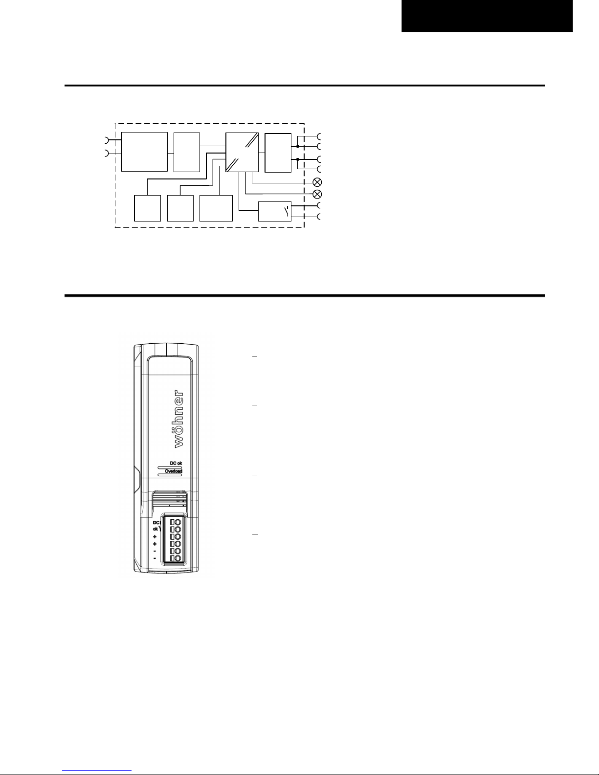
Fig. 12-1
Functional diagram
13. F
RONT SIDE AND USER ELEMENTS
Fig. 13-1
Front side
A DC-OK LED
The LED is on when the output voltage of a running device is above
20V.
B Overload LED
The LED is on when the output voltage falls below 19V or in case of a
short circuit in the output.
The LED is flashing when the device has switched off due to overtemperature. Input voltage is required.
C Output Terminals
(push-in terminals)
(two identical + poles and two identical - poles)
+
Positive output
–
Negative (return) output
D DC-OK Relay Contact
(push-in terminals)
Monitors the output voltage, see chapter 7 for details.
+
+
-
-
Output
Over-
Volt age
Protection
PFC
Converter
Power
Converter
Output
Filter
Output
Power
Manager
Temper-
ature
Shut-
down
Input Fuse
Input Filter
Input Rectif ier
Inrush Current
Limiter
L1
DC-OK
Contact
DC-OK
LED
DC-ok
Relay
L2
Overload
LED
Page 30
Revision 1, status Nov. 2017 30
English.
14. EMC
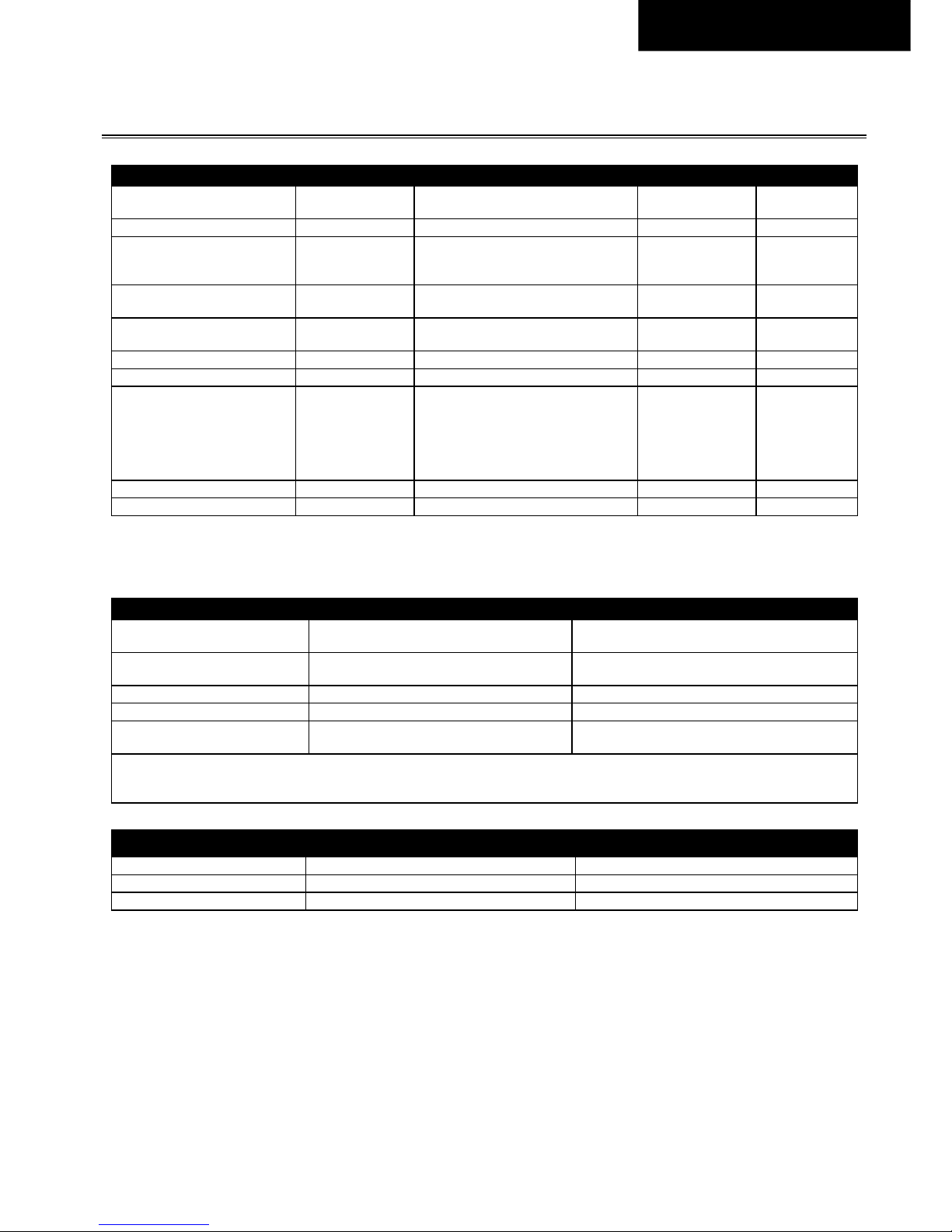
EMC Immunity According to EN 61204-3
Electrostatic discharge EN 61000-4-2
Contact discharge
Air discharge
8kV
8kV
Criterion A
Criterion A
Electromagnetic RF field EN 61000-4-3 80MHz - 6GHz T.b.d. Criterion A
Fast transients (Burst) EN 61000-4-4
Input lines
Output lines
DC-OK signal (coupling clamp)
4kV
2kV
2kV
Criterion A
Criterion A
Criterion A
Surge voltage on input EN 61000-4-5 T.b.d.
2kV
4kV
Criterion A
Criterion A
Surge voltage on output EN 61000-4-5 T.b.d.
1kV
2kV
Criterion A
Criterion A
Surge voltage on Signals EN 61000-4-5 T.b.d. 1kV Criterion A
Conducted disturbance EN 61000-4-6 0.15-80MHz T.b.d. Criterion A
Mains voltage dips EN 61000-4-11
0% of 380Vac
40% of 380Vac
70% of 380Vac
0% of 480Vac
40% of 480Vac
70% of 480Vac
0Vac, 20ms
152Vac, 200ms
266Vac, 500ms
0Vac, 20ms
192Vac, 200ms
336Vac, 500ms
Criterion A
Criterion B
Criterion B
Criterion A
Criterion B
Criterion A
Voltage interruptions EN 61000-4-11 0% of 380Vac (=0V) 5000ms Criterion B
Powerful transients VDE 0160 Over entire load range 1584V, 1.3ms Criterion A
Criterions:
A:
Power supply shows normal operation behavior within the defined limits.
B:
Temporary loss of function or performance during the tests - self recoverable.
EMC Emission According to EN 61204-3
Conducted emission
input lines
EN 55011, EN 55015, EN 55022, FCC Part 15,
CISPR 11, CISPR 22
Class A
Conducted emission
output lines 2)
IEC/CISPR 16-1-2, IEC/CISPR 16-2-1 Not required, not considered to be a DC-mains
Radiated emission EN 55011, EN 55022 Class A
Harmonic input current EN 61000-3-2 Class A fulfilled
Voltage fluctuations, flicker EN 61000-3-3
Fulfilled, tested with constant current loads, non
pulsing
This device complies with FCC Part 15 rules.
Operation is subjected to following two conditions: (1) this device may not cause harmful interference, and (2) this device must accept any
interference received, including interference that may cause undesired operation.
Switching Frequencies
PFC converter 25-120kHz Input voltage dependent
Main converter 100 to 130kHz Output load dependent
Auxiliary converter 30kHz Fixed frequency
Page 31
Revision 1, status Nov. 2017 31
English.
15. E
NVIRONMENT
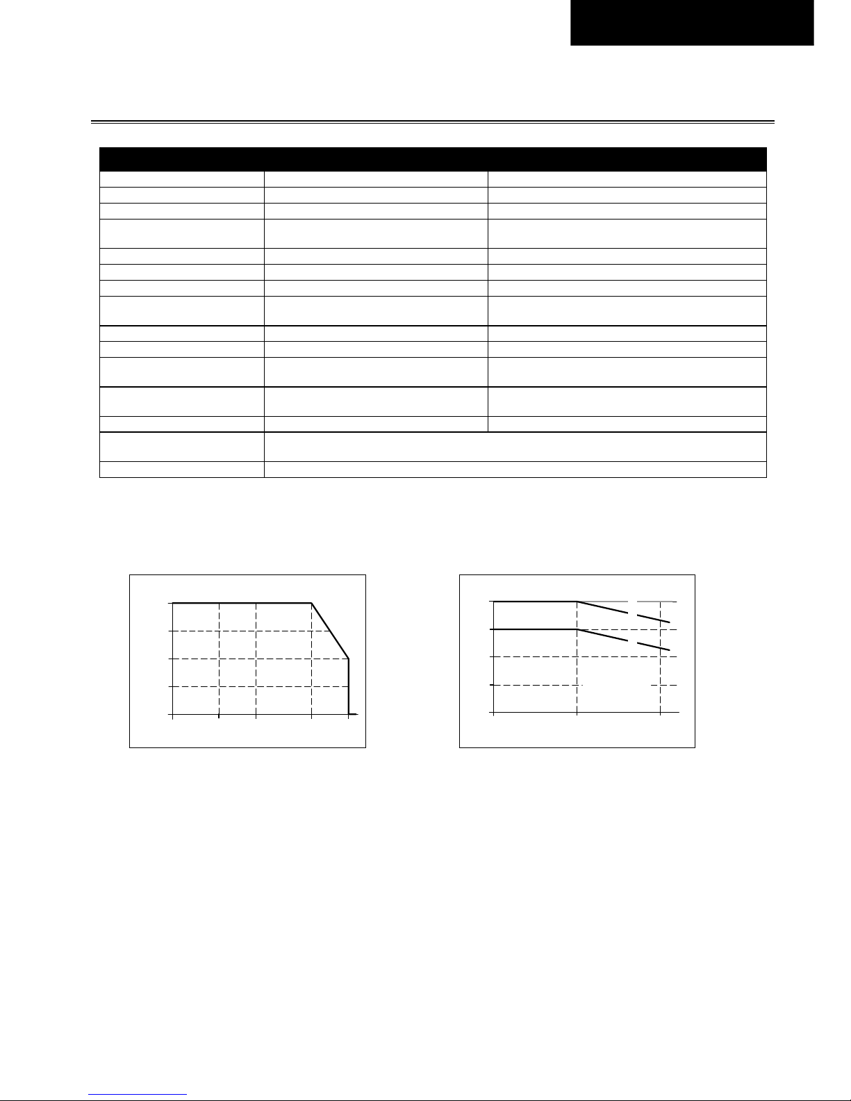
Operational temperature 1) -25°C to +70°C (-13°F to 158°F) Reduce output power according to Fig. 15-1
Storage temperature -40°C to +85°C (-40°F to 185°F) For storage and transportation
Output de-rating 6W/°C Between +50°C and +70°C (122°F to 158°F)
Humidity 5 to 95% r.h.
According to IEC 60068-2-30
Do not energize while condensation is present.
Vibration sinusoidal 2) T.b.d. According to IEC 60068-2-6
Shock 2) T.b.d. According to IEC 60068-2-27
Altitude 0 to 2000m (0 to 6 560ft) Without any restrictions
2000 to 4000m (6 560 to 13 120ft)
Reduce output power or ambient temperature, see Fig.
15-2.
Altitude de-rating 15W/1000m or 5°C/1000m Above 2000m (6500ft), see Fig. 15-2
Over-voltage category T.b.d. According to IEC 62477-1 for altitudes up to 2000m
T.b.d.
According to IEC 60950-1 for altitudes from 2000m to
4000m
T.b.d.
According to IEC 62477-1 for altitudes from 2000m to
4000m
Degree of pollution 2 According to IEC 62477-1, not conductive
LABS compatibility
The unit does not release any silicone or other LABS-critical substances and is suitable for use in paint
shops.
Audible noise Some audible noise may be emitted from the power supply during no load, overload or short circuit.
1) Operational temperature is the same as the ambient or surrounding temperature and is defined as the air temperature 2cm below the unit.
2) Tested when device is mounted onto the CrossBoard.
Fig. 15-1
Output current vs. ambient
temp.
Fig. 15-2
Output current vs. altitude
0
0 +20 +50
+70°C
2.5A
5.0A
7.5A
10A
Allowable Output Current
Ambient Temperature
-25
0
0
2000m
4000m
2.5A
5A
10A
7.5A
Allowed Output Current
Altitude
B
C
A
... Tam
b
< 60°C
B
... Tamb
< 50°
C
C
.
.. Short
t
erm
A
Page 32
Revision 1, status Nov. 2017 32
English.
16. S
AFETY AND PROTECTION FEATURES
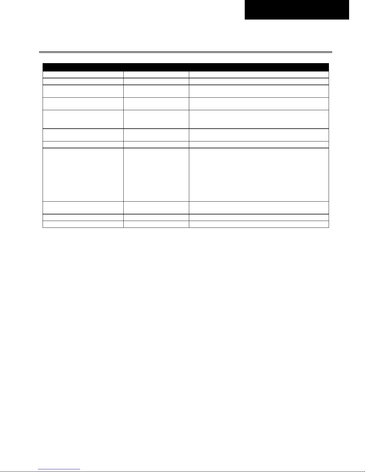
Input / output separation Double or reinforced galvanic isolation
SELV According to IEC/EN 60950-1
PELV According to IEC/EN 60204-1, EN 62477-1, IEC 60364-4-41
Isolation resistance > 500MOhm
At delivered condition between input and output, measured with
500Vdc
> 500MOhm
At delivered condition between output and DC-OK contacts,
measured with 500Vdc
Output over-voltage protection
Typ. 30.5Vdc
Max. 32Vdc
In case of an internal power supply defect, a redundant circuit
limits the maximum output voltage. The output shuts down and
automatically attempts to restart.
Class of protection II
According to IEC 61140
A PE (Protective Earth) connection is not required
Degree of protection IP 30 EN/IEC 60529
Over-temperature protection Yes
Output shut-down with automatic restart.
The temperature sensor is installed on critical components inside
the unit and turns the unit off in safety critical situations, which
can happen e.g. when de-rating requirements are not observed,
ambient temperature is too high, ventilation is obstructed or the
de-rating requirements for different mounting orientation is not
followed. There is no correlation between the operating
temperature and turn-off temperature since this is dependent on
input voltage, load and installation methods.
Input transient protection
MOV
(Metal Oxide Varistor)
For protection values see chapter 14 (EMC).
Internal input fuse Included Not user replaceable slow-blow high-braking capacity fuse.
Touch current (leakage current) Max. 0.25mA
Page 33
Revision 1, status Nov. 2017 33
English.
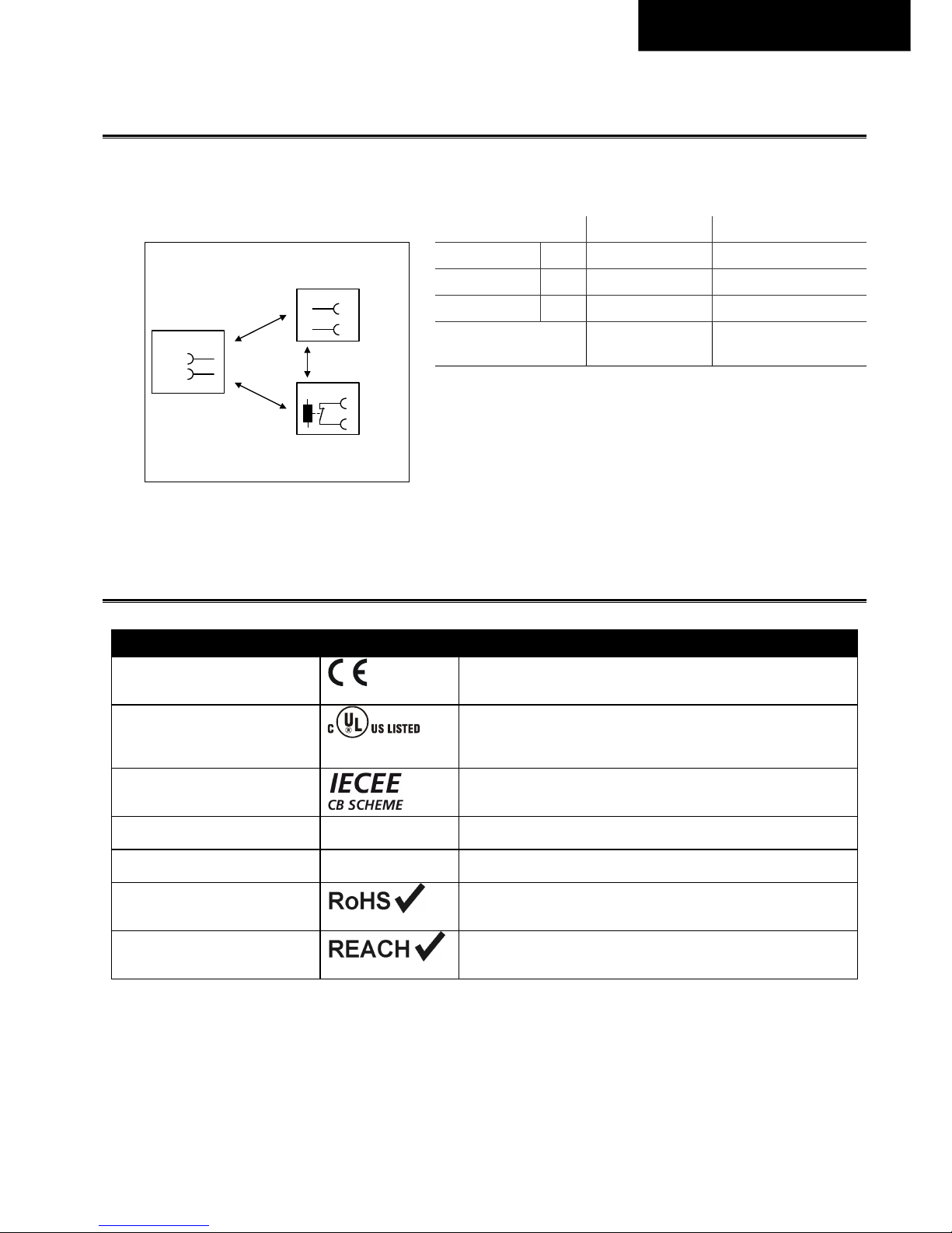
17. D
IELECTRIC STRENGTH
The output voltage is floating and has no ohmic connection to the ground. Type and factory tests are conducted by the
manufacturer. Field tests may be conducted in the field using the appropriate test equipment which applies the voltage with a
slow ramp (2s up and 2s down). Connect all input-terminals together as well as all output poles before conducting the test.
When testing, set the cut-off current settings to the value in the table below.
Fig. 17-1
Dielectric strength A B
Type test 60s 3400Vac 500Vac
Factory test 5s 2500Vac 500Vac
Field test 5s 2000Vac 500Vac
Cut-off current setting
for field test
> 2mA > 1mA
To fulfil the PELV requirements according to EN 60204-1 § 6.4.1, we
recommend that either the + pole, the – pole or any other part of the
output circuit shall be connected to the protective earth system. This
helps to avoid situations in which a load starts unexpectedly or can not
be switched off when unnoticed earth faults occur.
B*) When testing input to DC-OK ensure that the maximal voltage between DC-OK and the output is not exceeded
(column D). We recommend connecting DC-OK pins and the output pins together when performing the test.
18. N
ORMS AND APPROVALS
EC Declaration of Conformity
The CE mark indicates conformance with the
- EMC directive and the
- Low-voltage directive (LVD).
UL 61010-2-201
planned
Safety Requirements for Electrical Equipment for Measurement, Control,
and Laboratory Use
Part 2-201: Particular Requirements for Control Equipment;
Listed product E-File: T.b.d.
IEC 61010-2-201
planned
CB-Scheme Safety Requirements for Electrical Equipment for
Measurement, Control, and Laboratory Use
Part 2-201: Particular Requirements for Control Equipment
IEC 62477-1
T.b.d.
Safety requirements for power electronic converter systems and
equipment T.b.d.
IEC/EN 61558-2-16
(Annex BB)
Safety Isolating
Transformer
Safety Isolating Transformers corresponding to Part 2-6 of the IEC/EN
61558
RoHS Directive
Directive 2011/65/EU of the European Parliament and the Council of June
8th, 2011 on the restriction of the use of certain hazardous substances in
electrical and electronic equipment.
REACH Directive
Directive 1907/2006/EU of the European Parliament and the Council of
June 1st, 2007 regarding the Registration, Evaluation, Authorisation and
Restriction of Chemicals (REACH)
B
A
A
*
)
L1
Input
DC-ok
Output
+
-
L2
IND. CONT. EQ.
Page 34
Revision 1, status Nov. 2017 34
English.
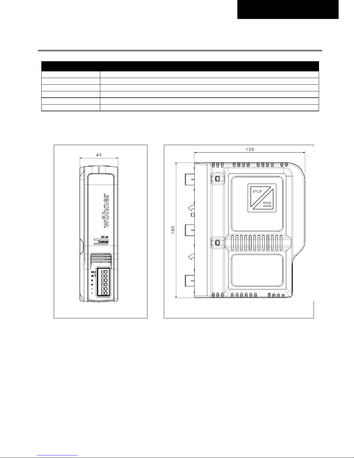
19. P
HYSICAL DIMENSIONS AND WEIGHT
Width 45mm 1.77’’
Height 160mm 6.3’’
Depth 130mm 5.12’’
Weight 550g / 1.21lb
Housing material T.b.d.
Installation clearances See chapter 2
Fig. 19-1
Front view
Fig. 19-2
Side view
All dimensions in mm
Page 35
Revision 1, status Nov. 2017 35
English.
20. A
PPLICATION NOTES
20.1. B
ACK-FEEDING LOADS
Loads such as decelerating motors and inductors can feed voltage back to the power supply. This feature is also called return
voltage immunity or resistance against Back- E.M.F. (Electro Magnetic Force).
This power supply is resistant and does not show malfunctioning when a load feeds back voltage to the power supply. It does
not matter whether the power supply is on or off.
The maximum allowed feed-back-voltage is 35Vdc. The absorbing energy can be calculated according to the built-in large sized
output capacitor which is specified in chapter 5.
20.2. S
ERIES OPERATION
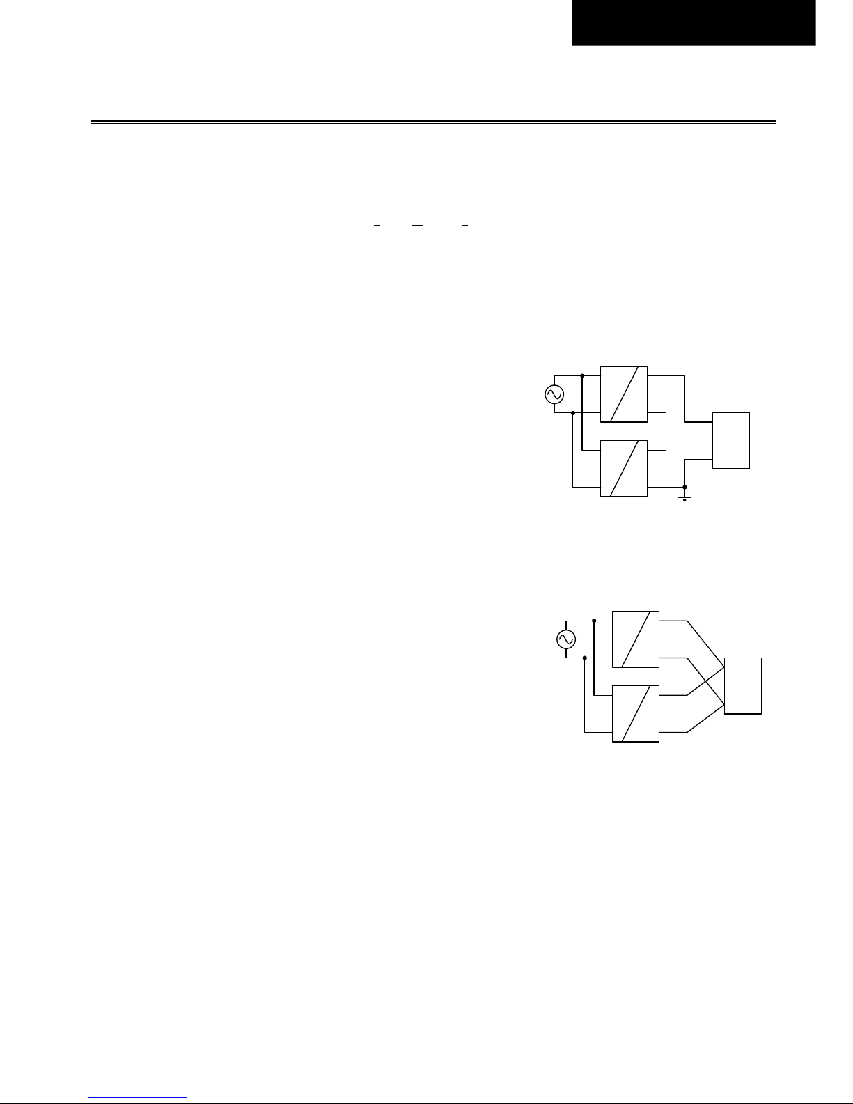
Up to three power supplies can be connected in series for higher output voltages.
Please note: Voltages with a potential above 60Vdc are not SELV any more and can
be dangerous. Such voltages must be installed with a protection against touching.
Earthing of the output is required when the sum of the output voltage is above
60Vdc.
Avoid return voltage (e.g. from a decelerating motor or battery) which is applied to
the output terminals.
Pay attention that leakage current, EMI, inrush current, harmonics will increase
when using multiple power supplies.
20.3. P
ARALLEL USE TO INCREASE OUTPUT POWER
A parallel connection of power supplies for higher output power is allowed for
ambient temperatures up to +45°C.
The device is featured with a “soft output regulation characteristic” (Parallel Use
Mode) in order to achieve current share between multiple devices, when they are
connected in parallel. The “soft output regulation characteristic” regulates the output
voltage in such a manner, that the voltage at no load is approx. 4% higher than at
10A load. See also chapter 5.
If more than three units are connected in parallel, a fuse or circuit breaker with a
rating of 15A or 16A is required on each output. Alternatively, a diode or redundancy module can also be utilized.
Energize all units at the same time to avoid the overload Hiccup
PLUS
mode. It also might be necessary to cycle the input power
(turn-off for at least five seconds), if the output was in Hiccup
PLUS
mode due to overload or short circuits and the required output
current is higher than the current of one unit.
Pay attention that leakage current, EMI, inrush current, harmonics will increase when using multiple power supplies.
Unit A
AC
DC
Unit B
AC
DC
-
+
-
+
Load
+
-
Unit A
AC
DC
Unit B
AC
DC
-
+
-
+
Load
+
-
Earth
(see notes)
 Loading...