

Page 1
VMQ Series
VMQ-4 / VMQ-2D / VMQ-SDI
1U Monitor Speaker Unit with 4 Analog Inputs
or 2 AES/EBU Inputs or 1 SDI Input, with
4 Analog Outputs, 4 Separate Volume Controls
w/mutes, and 4 Signal Indication LEDs
Document P/N 821504 Rev-D
User Manual
CONTENTS
Title and Contents ...............................................................
Introduction .................................................................................
Section 1: Features and Specifications...................
Description and Features .............................................................
Applications, Specifications, and Rear Panel Configurations ...........
Section 2: Operation .........................................................
Installation ...................................................................................
Front Panel Features ...................................................................
Rear Panel Features ....................................................................
Section 3: Technical Information ..............................
General Mechanical Observations ................................................
1
2
3
4
5
7
8
10
12
15
16
Audio Circuit Description ............................................................
Interconnect Block Diagrams .......................................................
© 2006 Wohler Technologies Inc. ALL rights reserved
16
17
1
Page 2

VMQ Series User Manual P/N 821504 Rev-D
Important Safety Instructions
1) Read these instructions.
2) Keep these instructions.
3) Heed all warnings.
4) Follow all instructions.
5) Do not use this apparatus near water.
6) Clean only with dry cloth.
Introduction
7) Do not block any ventilation openings. Install in accordance with the manufacturer's instructions.
8) Do not install near any heat source such as radiators, heat registers, stoves, or other apparatus (including
amplifiers) that produce heat.
9) Do not defeat the safety purpose of the polarized or grounding-type plug. A polarized plug has two blades
with one wider than the other. A grounding type plug has two blades and a third grounding prong. The
wide blade or the third prong are provided for your safety. If the provided plug does not fit into your outlet,
consult an electrician for replacement of the obsolete outlet.
10) Protect the power cord from being walked on or pinched, particularly at plugs convenience receptacles
and the point where they exit from the apparatus.
11) Only use attachments/accessories specified by the manufacturer.
12) Use only with the cart stand, tripod, bracket, or table specified by the manufacturer, or sold with the
apparatus. When a cart is used, use caution when moving the cart/apparatus combination to avoid injury
from tip-over.
13) Unplug this apparatus during lightning storms or when unused for long periods of time.
14) Refer all servicing to qualified service personnel. Servicing is required when the apparatus has been
damaged in any way, such as when power-supply cord or plug is damaged, liquid has been spilled or
objects have fallen into the apparatus, the apparatus has been exposed to rain or moisture, does not
operate normally, or has been dropped.
15) Do not expose this apparatus to rain or moisture.
16) The apparatus shall be connected to a mains socket outlet with a protective earthing connection.
CAUTION!
In products featuring an audio amplifier and speakers, the surface at the side of the
unit, where the audio amplifier heat sink is internally attached, may get very hot after
extended operation. When operating the unit excercise caution when touching this
surface and ensure that external materials which may be adversely affected by heat
are not in contact with it. There is a Hot Surface label (see diagram) attached to the
aforementioned surface of the product.
Introduction
Congratulations on your selection of a Wohler Technologies VMQ Series audio monitor unit. We are confident it represents the best
performance and value available, and we guarantee your satisfaction with it.
If you have questions or comments you may contact us at:
Wohler Technologies, Inc.
Phone: (510) 870-0810 Fax: (510) 870-0811
Phone: (510) 589-5676 Fax: (510) 870-0811
web: www.wohler.com e-mail: support@wohler.com
www.wohler.com [email protected]
2
© 2006 Wohler Technologies Inc. ALL rights reserved
Wohler Technologies, Inc.
31055 Huntwood Avenue
31055 Huntwood Avenue
Hayward, CA 94544
Hayward, CA 94544
US Toll-Free: 1-888-596-4537
US Toll-Free: 1-888-596-4537
Page 3

VMQ Series User Manual P/N 821504 Rev-D
General Features
and Specifications
Rear Panel Configurations
Sect. 1: General Features and Specifications
Section 1
Description
Features
Applications
Specifications
© 2006 Wohler Technologies Inc. ALL rights reserved
3
Page 4
VMQ Series User Manual P/N 821504 Rev-D
VMQ Series
Four-Channel Audio Monitoring Units
Section 1: General Features and Specifications
WOHLER
TECHNOLOGIES
WOHLER
TECHNOLOGIES
WOHLER
TECHNOLOGIES
1
1
1
MUTE/
ACTIVITY
MUTE/
ACTIVITY
MUTE/
ACTIVITY
2
VMQ-4 Front Panel
2
POWER
AES2AES1
VMQ-2D Front Panel
2
SDI
VMQ-SDI Front Panel
3
3
3
MUTE/
ACTIVITY
MUTE/
ACTIVITY
MUTE/
ACTIVITY
4
VMQ-4
ANALOG AUDIO
MONITOR PANEL
4
VMQ-2D
DIGITAL AUDIO
MONITOR PANEL
4
VMQ-SDI
DIGITAL AUDIO
MONITOR PANEL
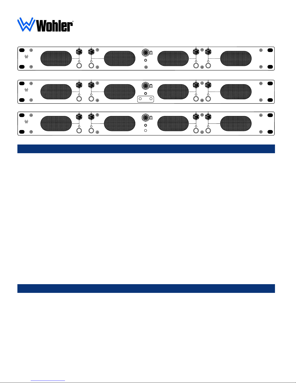
Description
The single-rackspace VMQ series from Wohler Technologies permits simultaneous monitoring of up to four audio
sources with “voice quality” fidelity.
Because each channel has its own dedicated power amplifier and speaker, the audio sources remain completely
separate from analog input to output. When listening within “Ultra Near Field” distances of 1 to 3 feet, these discrete
speaker outputs provide enhanced source distinction when compared to designs with four inputs mixed into a single
output.
Three models are available; the VMQ-4, which accepts four standard analog inputs, the VMQ-2D, which accepts
two AES/EBU inputs (two sub-channels each), and the VMQ-SDI, which accepts one SDI input (four sub-channels).
A separate volume control is provided for each of the four monitored channels. Also, each channel has an LED, which
illuminates when a signal is "active" in that channel. This allows the operator to easily determine which VMQ-4
channels are currently active, and is very helpful when quick volume adjustments are required. Separate mute buttons
are provided for each channel. These together with an LED that indicates channel muting allows the operator to
instantly mute one or more channels and determine, at a glance which channels are muted.
A stereo headphone jack has channels 1 and 2 summed on the left side, and channels 3 and 4 on the right side.
The VMQ series is fully magnetically shielded to allow operation immediately adjacent to all CRT video monitors.
Its light weight and shallow-depth chassis make it ideal for use in portable and mobile vehicle applications.
Features
•Only ONE rack space high.
•Monitoring of four discrete audio channels in one
unit.
•Three models available:
VMQ-4 with four analog inputs
VMQ-2D with two AES/EBU inputs
VMQ-SDI with one SDI input
•Volume control for each of four channels.
•Fully magnetically shielded.
•Signal present LED on each channel output.
•Digital signal light for AES/EBU and SDI models
•Mute button and LED for each channel.
•Headphone jack
•Dedicated input circuitry for each output channel.
4
© 2006 Wohler Technologies Inc. ALL rights reserved
Page 5
VMQ Series User Manual P/N 821504 Rev-D Section 1: General Features and Specifications
Applications
•Monitoring multiple incoming feeds for news /talk
shows
•Confidence/cueing monitoring for D2- , D3- and
D5-typeVTRs in machine rooms and edit bays
Specifications
Input impedance:
Input level for full output:
(volume full on)
Hum and noise:
Frequency response:
Maximum acoustic output:
Greater than:
100 kΩ (Ohm) balanced
50 kΩ (Ohm) unbalanced
0 dBv balanced.
-12dBv unbalanced
Other sensitivity ranges available
on request
Better than -70 dB below full
output
300 Hz to 16 kHz (± 9dB)
94 dB SPL at 2 feet
•Monitoring of multiple inputs in TV newsrooms
•Monitoring multiple audio feeds in theme parks,
security installations, and teleconferencing systems
Magnetic shielding:
Connectors:
Dimensions (HxWxD):
Weight:
Power Supply:
Power consumption:
Less than 0.2 Gauss any adjacent
surface
Balanced: Phoenix (Standard)
or XLR (Optional)
1.75 x 19 x 9.7 in.
44.5 x 483 x 246 mm.
7 lbs. (3.2 kg)
Universal AC input (100-240V) UL/
CSA approved
20W / 35W (avg. / max)
Electrical distortion:
POWER SUPPLY
APPROVALS
R
US
C
SEE SIDE FOR ADDITIONAL APPROVALS
MODEL
50-60 Hz
100-240 VAC
Less than 0.2% at any level below
limiting threshold
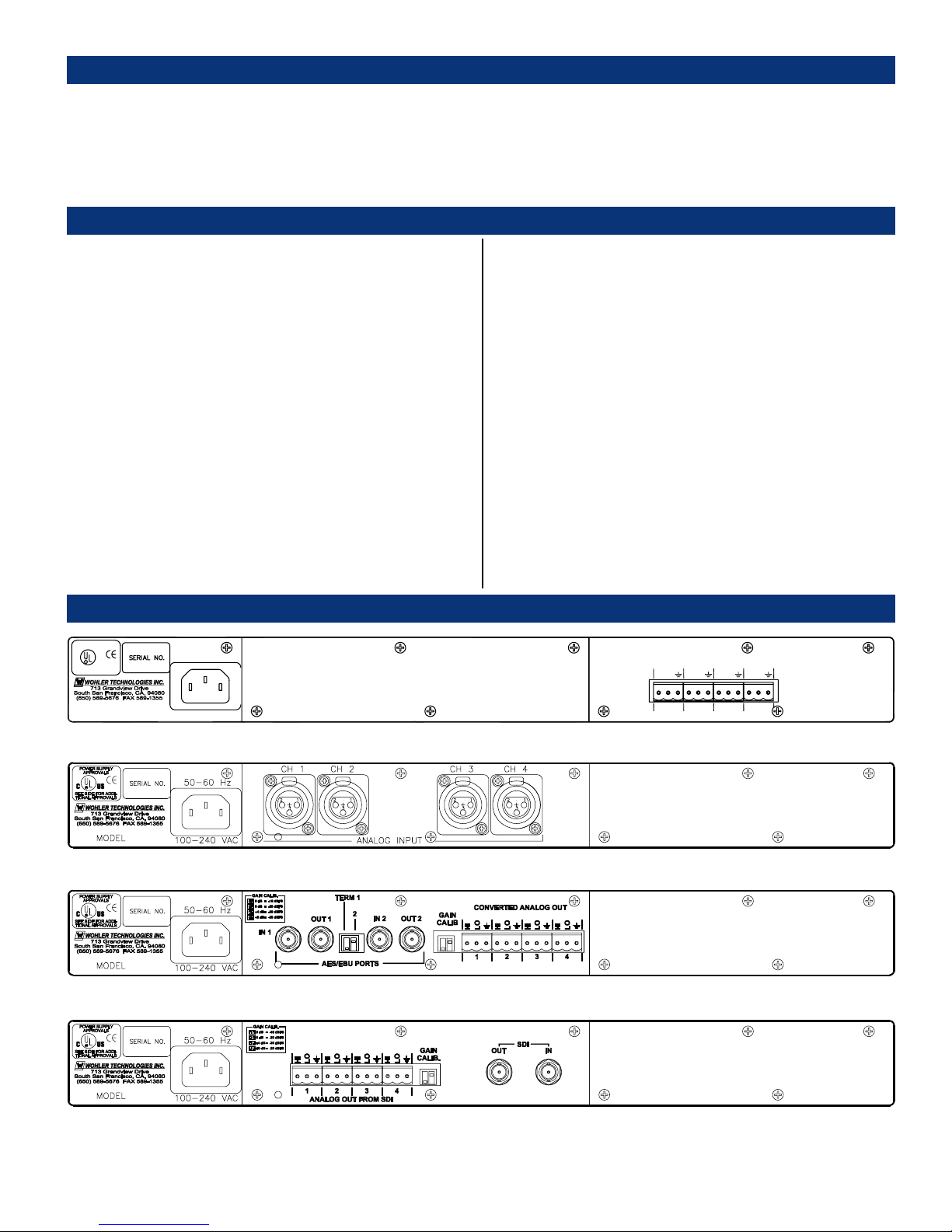
Rear Panel Configurations
VMQ-4 Rear Panel
VMQ-4/X Rear Panel (With XLR Connectors)
VMQ-2D Rear Panel
LO
HI
1
ANALOG IN
HI
LO
LO
HI
2 3 4
HI
LO
Units are certified to meet, at time of manufacture, all currently applicable product safety and EMC requirements, such as those of UL
and CE. 0 dbV ref. 0.775V RMS. Features and specifications subject to improvement without notice.
© 2006 Wohler Technologies Inc. ALL rights reserved
VMQ-SDI Rear Panel
5
Page 6

VMQ Series User Manual P/N 821504 Rev-D
6
© 2006 Wohler Technologies Inc. ALL rights reserved
(This page left intentionally blank)
Page 7

VMQ Series User Manual P/N 821504 Rev-D
Section 2
Operation
Installation
Front Panel Features
Rear Panel Features
© 2006 Wohler Technologies Inc. ALL rights reserved
7
Page 8

VMQ Series User Manual P/N 821504 Rev-D Section 2: Operation
Installation
Mounting
The unit should be mounted where convenient for operating persons, ideally at approximately ear level for best
high frequency response. Its superior magnetic shielding eliminates concerns about locating it adjacent to most
types of CRT monitors, including even high-resolution color monitors.
Heat Dissipation
Heat dissipated by the speaker amps is conducted directly to the sides of the chassis; no special considerations
for cooling are necessary as long as the ambient temperature inside the rack area does not exceed approximately
40°C (104°F).
Sympathetic Vibration
Sympathetic vibration from other equipment (cables, etc.), in the rack may be serious enough to interfere with
the unit’s sound quality out in the listening area. The use of thin card stock and/or felt or foam weather-stripping
type materials between adjacent vibrating surfaces, or tying up loose cables, etc., may be required to stop
vibrations external to the unit.
Mechanical Bracing
The chassis is securely attached to the front panel at eight points along its surface, not just at the four corners of
the chassis ears. This feature will reduce or eliminate rear bracing requirements in many mobile/portable
applications. The weight of internal components is distributed fairly evenly around the unit.
Electrical Interference
As with any audio equipment, maximum immunity from electrical interference requires the use of shielded cable;
however, satisfactory results can sometimes be obtained without it. The internal circuitry common is connected
to the chassis. In the VMQ-4 (standard analog inputs), unbalanced sources may also be applied to the balanced
inputs. For analog input signals, the gain is 6 dB greater with a single-ended source connected across both “hot”
terminals than when connected between either input and common. Note that the unused input terminal of a
balanced input should be connected to common, rather than being left floating, to insure best immunity to noise.
AC Power
The unit's AC mains connection is via a standard IEC inlet, with safety ground connected directly to the unit's
chassis. The universal AC input (100-240VAC, 50/60Hz) switching power supply is a self-resetting sealed
type, with automatic over-voltage and over-current shutdown. There is no user-replaceable fuse in either the
primary or secondary circuit.
Magnetic Shielding
We have defined five levels of magnetic shielding. Level One represents the most minimal shielding of the steel
chassis compared to the stray field of the speakers without any ferro-magnetic enclosure. Level One typically
results in a field strength of two Gauss at a distance of two inches from the enclosure surface. (Because of the
inverse square law, such a field is eight Gauss at one inch from the surface!) Because of the purity of color of
the CRT display, it is extaordinarily sensitve to magnetic fields making Level One shielding inadequate, even if
the CRT is several rackspaces away. (CRT color purity may be distrubed by fields as low as 1/2 Gauss.)
Level Two shielding, specifed as two Gauss or less anywhere along the top and bottom surfaces and front panel,
was an interim level, and is sometimes the best available for highly customized units, but is satisfactory in many
applications.
8
© 2006 Wohler Technologies Inc. ALL rights reserved
Page 9

VMQ Series User Manual P/N 821504 Rev-D
Section 2: Operation
Installation
Magnetic Shielding (Cont.)
The VMQ series employes proprietary methods to achieve Level Three shielding, which is specified as one to
1.5 Gauss or less
at the surface, anywhere along the top or bottom of the chassis and front panel. (The VMQ has
stray field of about 1 Guass.) For all situations we are aware of, this level has proved to be entirely
satisfactory. With Level Three shielding, the unit may be located in the rackspace
immediately above, below or
to either side of a color monitor, usually without distrubing the purity at all.
Audio Connections
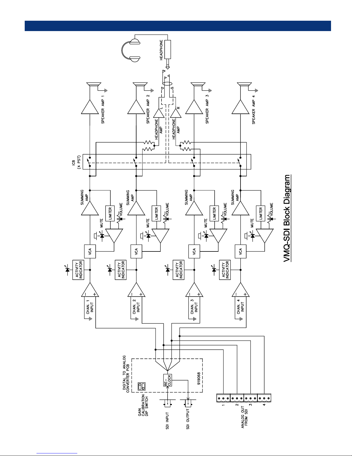
Connection of the audio feeds is straightforward. The system block diagrams located on pages 17, 18 and 19
may be referred to for clarification of the general signal paths into and out of the VMQ units.
Please note the following:
1) The internal circuitry common is connected to the chassis.
2) If RCA phono inputs (unbalanced) were ordered for the VMQ-4 unit, they have approximately 12dB more
gain than the XLR (balanced) connectors for use with equipment which has "consumer" line level outputs (-10
to-15 dBv). Higher level unbalanced sources may be applied to the balanced inputs for increased headroom.
The gain is approximately 4dB greater with a single-ended source connected across both "hot" terminals than
when connected between either input and common.
NOTE: Unless otherwise noted, all chassis mounted XLR and BNC connectors are female.
© 2006 Wohler Technologies Inc. ALL rights reserved
9
Page 10

VMQ Series User Manual P/N 821504 Rev-D
Section 2: Operation
Front Panel Features
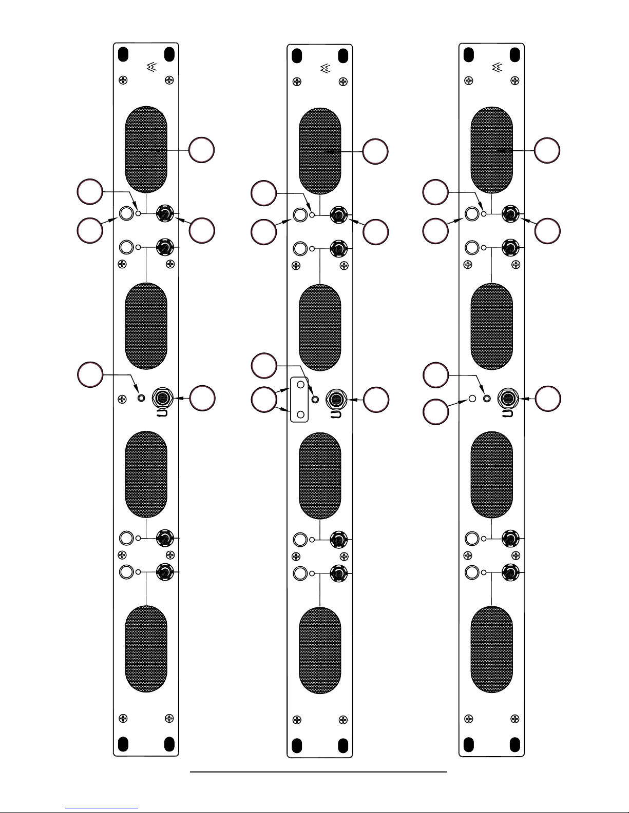
Please refer to Figure-2a on the following page to familiarize yourself with the front panel features of the three
VMQ models. The following sections describe these features and are referenced, by number, to Figure-2a.
1 Internal Speakers (4 places)
The VMQ internal speaker system is comprised of four separate mid-range speakers. From left to right the
speakers correspond to channels 1 through 4; one speaker for each of the four channels.
2 Volume Controls (4 places) - Rotary Pots
Each volume control adjusts the loudness of the audio reproduced by the associated internal speakers of
the respective channel (or connected headphone). From left to right the volume controls correspond to
channels 1 through 4.
3 Headphone Jack - 1/4" Phone Plug
For critical listening or for listening in high noise environments, use the headphone feature rather than the
internal speakers. When being monitored by headphones, channels 1 and 2 are summed to the left headphone
while channels 3 and 4 are summed to the right. When you plug in headphones, the speakers will mute. This
jack accepts the standard 1/4” phone type stereo plug.
4 Channel Mute Indication (4 places) - Red LED
There is a Channel Mute Indicator LED for each of four channels and each LED will glow red to indicate
the mute feature is being used on the associated channel. From left to right the Channel Mute buttons
correspond to channels 1 through 4.
5 Mute Button / Channel Activity Indication (4 places) - Push Button/
Amber LED
Mute Button: There is a Mute Button for each of four channels. When depressed, these buttons toggle the
mute feature on and off for the associated channel. When a channel is muted, the LED above the associated
button will glow red (Item 4, above).
Channel Activity Indicator: Signal activity in any given channel will cause the LED in the associated
button for that channel to glow amber.
6 Power Indication - Green LED
The Power Indicator LED signals the operating condition of the power supply. The LED glows green to
indicate the VMQ-4 is connected to mains power and an operation voltage is present.
7 AES/EBU Signal Indication - Red/Green Bi-color LED (VMQ-2D Only)
These two LEDs each glow green to indicate the presence of valid AES/EBU signals (one for each of two
inputs) and each will glow red to indicate the absence of such signals in the associated input.
8 SDI Indication - Red/Green Bi-color LED (VMQ-SDI Only)
This LED glows green to indicate the presence of a valid SDI signal and will glow red to indicate possible
errors in the SDI signal. If there is no SDI signal, the LED will be unlit.
10
© 2006 Wohler Technologies Inc. ALL rights reserved
Page 11
VMQ Series User Manual P/N 821504 Rev-D
4 Places
4 Places
TECHNOLOGIES
WOHLER
TECHNOLOGIES
WOHLER
Section 2: Operation
TECHNOLOGIES
WOHLER
4 Places 4 Places
4
5
6
ACTIVITY
MUTE/
4 Places
1
4 Places 4 Places
4
1
4 Places
2
2
5
ACTIVITY
1
MUTE/
2
1
2
4 Places
4 Places
4
4 Places4 Places
5
ACTIVITY
MUTE/
1
1
2
2
6 8
AES1 AES2
3
76
POWER
3
3
SDI
3
ACTIVITY
MUTE/
4
VMQ-4
MONITOR PANEL
ANALOG AUDIO
VMQ-4
Figure-2a: VMQ Series Front Panel Features
© 2006 Wohler Technologies Inc. ALL rights reserved
ACTIVITY
MUTE/
VMQ-2D
3
4
MONITOR PANEL
DIGITAL AUDIO
VMQ-2D
ACTIVITY
MUTE/
VMQ-SDI
MONITOR PANEL
3
4
DIGITAL AUDIO
VMQ-SDI
11
Page 12
VMQ Series User Manual P/N 821504 Rev-D Section 2: Operation
Rear Panel Features
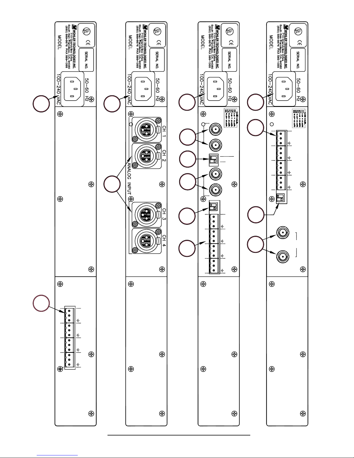
Please refer to Figure-2b on the following page to familiarize yourself with the rear panel features of the three
VMQ models. The following sections describe these features and are referenced, by letter, to Figure-2b.
A Power Input - IEC-320 Connector
Attach a standard IEC-320 power cord between this connector and mains power (100 - 250VAC, 50/60
Hz). The front panel power LED (Item 6, page 10) will glow green to indicate operating voltages are
present.
B Analog Inputs - Chan. 1-4 - Phoenix or XLR Connector (VMQ-4)
These four inputs are meant to receive standard analog audio signals and are configured for balanced
(100K Ohm) connections. Either Phoenix (standard) or XLR (optional) connectors may be specified at the
time of ordering the VMQ-4. Inputs are labeled 1 through 4. XLR connectors are 3-pin female and
Phoenix Connectors are standard 3-pin type. Pin-out information for Phoenix connectors are silk-screened
above each connector. XLR pin-outs are as follows: Pin-1 = common, Pin-2 = low, Pin-3 = high.
C AES/EBU Inputs and Outputs - Chan. 1-2 - BNC Connector (VMQ-2D)
The two BNC connector inputs (IN 1 and IN 2) are meant to receive standard AES/EBU digital audio
signals. There are also two re-clocked outputs (OUT 1 and OUT 2) derived from the two inputs. All BNC
connectors are female.
D SDI Input and Output - BNC Connector (VMQ-SDI)
The SDI input connector is meant to receive a standard SDI digital audio signal. The output is derived
from the input signal and is re-clocked. Both BNC connectors are females.
E Termination Select - 2-Position DIP Switch (VMQ-2D)
This DIP switch sets the termination characteristics of the AES/EBU input connectors. There are two
switches; one on the left (TERM 1) for the Channel 1 input/output, and one on the right (TERM 2) for the
Channel 2 input/output. In the event that signals entering a channel input are connected to terminated
downstream equipment via the OUT connectors (or external "T" conectors), the DIP switch associated
with that channel should be set to unterminated (UP). If there is no connection to downstream equipment,
then the DIP switch should be set to terminated (DOWN).
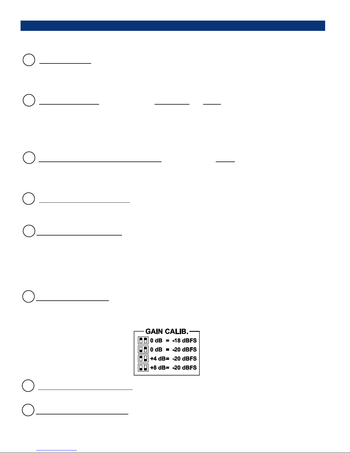
F Gain Calibration - 2-Position DIP Switch (VMQ-2D and VMQ-SDI)
Gain calibration, the analog level which corresponds to a given digital value, is settable via this DIP
switch. The factory setting is +4 dB = -20 dBFS. See below or the silk-screen on the rear panel for
settings.
G Converted Analog Out - Phoenix Connector (VMQ-2D)
These connectors output a converted analog signal of the four channels derived from the AES/EBU inputs.
H Analog Out From SDI - Phoenix Connector (VMQ-SDI)
These connectors output a converted analog signal of the four channels derived from the SDI input.
12
© 2006 Wohler Technologies Inc. ALL rights reserved
Page 13
VMQ Series User Manual P/N 821504 Rev-D
SEE SIDE FOR ADDI-
TIONAL APPROVALS
POWER SUPPLY
APPROVALS
R
USC
SEE SIDE FOR ADDI-
TIONAL APPROVALS
C
POWER SUPPLY
APPROVALS
R
US
SEE SIDE FOR ADDI-
TIONAL APPROVALS
C
POWER SUPPLY
APPROVALS
R
US
Section 2: Operation
SEE SIDE FOR ADDI-
TIONAL APPROVALS
C
POWER SUPPLY
APPROVALS
R
US
A B
BA
A
C
CE
F
G
IN 1
AES/EBU PORTS
1
2
43
OUT 1
OUT 2IN 2
CALIB
HI
LO
HI
LO
HI
LO
HI
LO
A
TERM 1
2
GAIN
F DH
CONVERTED ANALOG OUT
ANALOG OUT FROM SDI
HI
LO
HI
LO
HI
321
LO
HI
4
LO
CALIB.
GAIN
OUT IN
SDI
HI
1
LO
HI
LO
HI
LO
HI
LO
ANALOG IN
VMQ-4/X
2 3 4
VMQ-4
Figure-2b: VMQ Series Rear Panel Features
© 2006 Wohler Technologies Inc. ALL rights reserved
VMQ-2D
VMQ-SDI
13
Page 14

VMQ Series User Manual P/N 821504 Rev-D
14
© 2006 Wohler Technologies Inc. ALL rights reserved
(This page left intentionally blank)
Page 15

VMQ Series User Manual P/N 821504 Rev-D
Technical Information
General Mechanical Observations
Main Audio PCB - General Ciurcuit Description
VMQ-4 System Block Diagram
VMQ-2D System Block Diagram
VMQ-SDI System Block Diagram
Section 3
NOTE:
PCB layout and schematic support documentation is available upon request.
© 2006 Wohler Technologies Inc. ALL rights reserved
15
Page 16

VMQ Series User Manual P/N 821504 Rev-D
Section 3: Tecnical Information
General Mechanical Observations
Elimination of cabinet and component sympathetic vibrations (resonances) requires considerable attention to
mechanical details. Because of this, and the servere physical constraints of the speaker's acoustic enclosures,
seemingly minor changes to any of the mechanical details of the unit will frequently seriously impair its acoustic
performance. If mechanical work on the unit is absolutely necessary, be sure to make adequate notes to permit accurate
reassembly. Unfortunately, the unusual and wholly proprietary method of magnetic shielding is usually degraded
somewhat by ANY disassembly of the unit, except removal of the rear panel. The fuse for channels 1 and 2 is locted
along the back edge of the main circuit board near the power jack; it may be replaced by removing only the rear panel.
Almost any other maintenance or repair will require removal of the cover.
Audio Circuit Description
Input Section
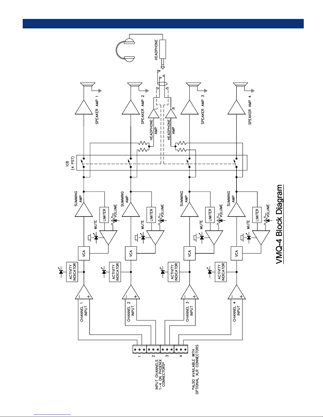
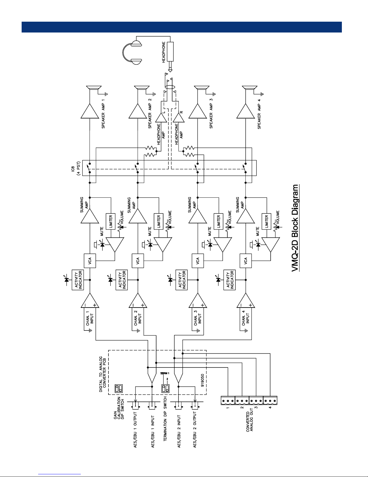
The balanced input is buffered by a differential input of the audio signal to dual op amp ICs 1and 2. The output of
ICs 1 and 2 goes to the input of the quad VCA (U7) after receiving a slight treble boost. The output also goes to a
quad, high-gain rectifier (IC8), used to drive the LED activity indicators, which indicate the presence of an input signal
in each channel.
Volume Controls
Volume controls are implemented through a quad VCA chip (U7). The control potentiometer for each VCA is buffered
by IC4 and IC5. Section A and B of the dual IC each buffer one volume control and an associated mute switch.
Clockwise rotation of the volume pot decreases the wiper voltage causing the IC4/5 output to rise, which decreases
the audio level of the VCA. The mute switch performs this function instantly by taking the IC4/5 inverting input directly
to ground.
Limiting Circuitry
The output of the four VCA’s are summed into IC6 and IC7 where the audio waveform’s conversion to voltage takes
place, and the rectified output from each of these stages is the input to a corresponding non-inverting section of IC4
and IC5. These non-inverting sections develop limiting control voltages for each VCA section. A voltage above 2
volts across D17, D18, D19, and D20 will cause a lower gain in the corresponding section of the VCA.
Headphone
The output of the four VCA’s (IC6 and IC7) is also the input circuitry for the headphone amplifier as well as the input
of the speaker amplifiers, through IC8. The signal passes through U8, a quad CMOS switch. The control input is
normally high (above 10 volts) on its way to the speaker amplifier; as well as going to the summing resistor pack
SP17, and capacitors C97 and C98 for use with an optional woofer. Channels 1 and 2, which are the outputs of IC6,
A and B, are also summed to the input of IC9, which drives the left headphone channel output. IC7, A and B, is summed
to the input of IC10 for the right headphone channel. Jumping JP13 will cause all signals to be summed to both
amplifiers, thus causing the entire signal to become monaural in the headset.
Headphone Output/Speaker Muting
While headphones are not plugged in, the output terminals are open circuit and the op amp DC bias supplied by R7
and R8 keeps pins 2 and 3 of H1 high. Plugging headphones in provides a shunt path to ground for this DC bias through
the headphones, which turns off transistors Q1 and Q2. This sets pins 9, 10, and 11 on analog switch U8 high, which
switches the signals that normally go to the speaker amps to AC ground (bias) instead. The RC networks of C9 and
C10/R9-R11 filter any high-level low frequency transients, which might otherwise affect Q1 and Q2. Note that for
this sensing circuit to work, the headphones MUST have a DC resistance not greater than about 1K ohm.
16
© 2006 Wohler Technologies Inc. ALL rights reserved
Page 17
VMQ Series User Manual P/N 821504 Rev-D
VMQ-4 - System Block Diagram
Section 3: Tecnical Information
© 2006 Wohler Technologies Inc. ALL rights reserved
17
Page 18
VMQ Series User Manual P/N 821504 Rev-D
VMQ-2D - System Block Diagram
Section 3: Tecnical Information
18
© 2006 Wohler Technologies Inc. ALL rights reserved
Page 19
VMQ Series User Manual P/N 821504 Rev-D
VMQ-SDI - System Block Diagram
Section 3: Tecnical Information
© 2006 Wohler Technologies Inc. ALL rights reserved
19
Page 20
VMQ Series User Manual P/N 821504 Rev-D
Wohler Technologies, Inc.
You can now contact us at:
31055 Huntwood Avenue
Wohler
Hayward, CA 94544
Technologies, Inc.
Phone: (510) 589-5676
31055 Huntwood Avenue
Fax: (510) 870-0811
Hayward, CA 94544
US Toll-Free: 1-888-596-4537
Phone: (510) 870-0810
web: www.wohler.com
Fax: (510) 870-0811
e-mail: support@wohler.com
US Toll-Free: 1-888-596-4537
www.wohler.com
20
© 2006 Wohler Technologies Inc. ALL rights reserved
 Loading...