

Page 1
The Measure of Technology
US
Manual
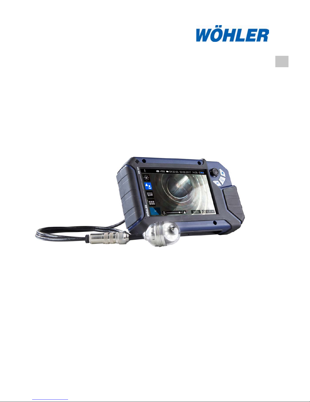
HD-Cable Camera
Wöhler VIS 700
Best.- Nr. 24308 2018-07-27
Page 2

Contents
2
Contents
1 General Information .............................. 4
1.1 Operation Manual Information ....................... 4
1.2 Copyright ....................................................... 4
1.3 Notes ............................................................. 4
1.4 Proper use ..................................................... 5
1.5 Scope of supply ............................................. 5
1.6 Storage and transport.................................... 6
1.7 Manufacturer ................................................. 6
2 Important information .......................... 7
3 Technical Data ....................................... 9
3.1 Monitor .......................................................... 9
3.2 Wöhler pan & tilt camera head .................... 10
3.3 Cable ........................................................... 12
3.4 Storage ........................................................ 12
4 Monitor ................................................. 13
5 Connecting the camera cable and
camera head ........................................ 16
5.1 Connecting the camera cable ...................... 16
5.2 Connecting the camera head ...................... 17
6 Starting up ........................................... 18
6.1 Activating the battery ................................... 18
6.2 Charging the rechargeable battery .............. 18
7 Handling the monitor .......................... 19
8 Keys and their functions .................... 21
8.1 On/Off key ................................................... 21
8.2 Video key .................................................... 22
8.3 Image key .................................................... 23
8.4 Joystick ....................................................... 23
9 Display elements................................. 24
10 Displayed position of the cam er a head
.............................................................. 25
11 Home function ..................................... 25
Page 3

Contents
3
12 Voice recording .................................. 25
13 Live menu ............................................ 26
13.1 Brightness menu .......................................... 26
13.2 Focus menu ................................................. 26
13.3 Comment function ........................................ 27
13.4 System menu ............................................... 29
13.4.1 Activate WLAN ............................................ 29
13.4.2 Locator ......................................................... 29
13.4.3 Saving and deleting images and videos ...... 30
13.4.4 Display images and videos .......................... 31
13.4.5 Settings ........................................................ 33
13.4.6 Info menu ..................................................... 35
14 Transmission of image files via WLAN
.............................................................. 36
14.1 Access Point: Transmission via a VIS 700-
WLAN-network ............................................. 37
14.2 Client: Using an existing WLAN network ..... 39
15 Faults ................................................... 41
15.1 Reset ........................................................... 41
15.2 Possible malfunctions .................................. 41
16 Maintenance ........................................ 42
16.1 Information on maintenance ........................ 42
16.2 Replacing the dome of the camera head ..... 42
16.3 Camera head ............................................... 42
16.4 Monitor ......................................................... 42
16.5 Cleaning the cable ....................................... 42
17 Guaranty and Service ......................... 43
17.1 Guaranty ...................................................... 43
17.2 Service ......................................................... 43
18 Declaration of conformity .................. 44
Page 4
General Information
4
1 General Information
1.1 Operation Manual In-
formation
This operation manual allows you to work safely
with the Wohler VIS 700. Please keep this manual
for your information.
The Wohler VIS 700 should be employed by professionals for its intended use only .
Liability is void for any damages caused by not
following this manual.
1.2 Copyright
Without previous authorization of Wohler it is not
allowed to reproduce, copy or translate this manual or part of this manual.
1.3 Notes
WARNING!
Not following this warning can cause injury or
death.
CAUTION!
Highlights risks that can lead to damage occurring
to the device.
NOTE!
Highlights tips and other usefu l inform at ion .
Page 5
General Information
5
1.4 Proper use
The Camera is designed to visually inspect and
document the condition of pipes and shafts, for
example in flue gas systems, ventilation systems
as well as for inspecting underground pipes etc .
The Camera is designed to be used by trained
specialists only.
Any other use is considered improper use.
1.5 Scope of supply
Device
Scope of supply
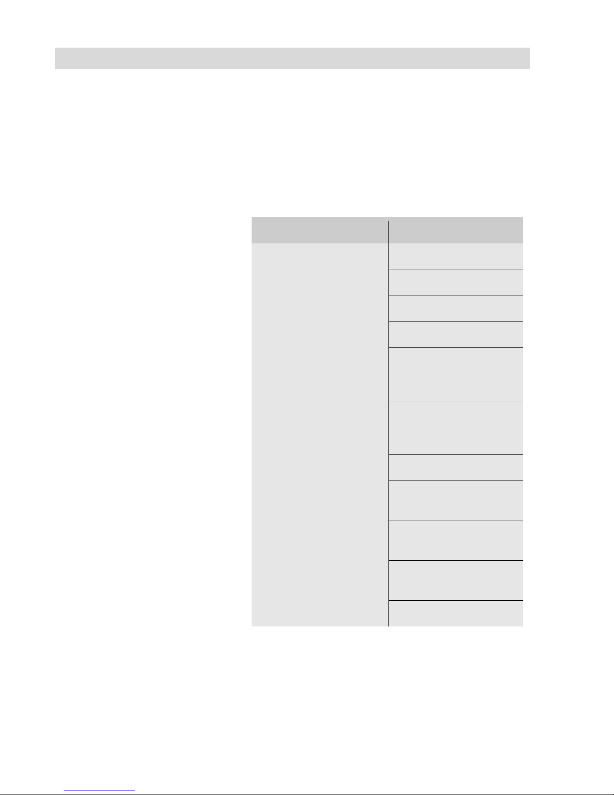
Wöhler VIS 700 HD-
Pushrod Camera
Monitor
Anti-glare protection
Lithium-ion battery
Riser syste m
Ø 1.5 inch pan and tilt
color camera head,
pluggable
Ø 1 inch miniature
camera head, pluggable (option)
SD- card 32 GB
Camera cable, 65 ft,
with metrication
3 replacement plastic
domes
1 USB power supply
with USN-C-cable
Plastic case
Page 6

General Information
6
1.6 Storage and transport
To avoid damage occurring during transport it is
imperative that the complete system is transported in the original case designed for the purpose.
1.7 Manufacturer
Wöhler Technik GmbH
Wöhler-Platz 1
33181 Bad Wünnenberg
Tel.: +49 2953 73-100
Fax: +49 2953 73-96100 ·
Email: [email protected]
www.woehler.com
Page 7
Important information
7
2 Important information
Eye protection
WARNING!
Never point a connected camera head at your own
or somebody else's eyes when the monitor is
switched on. The LEDs are extremely bright and
can dazzle.
Working environment
WARNING!
Only place the camera on firm level ground and
ensure a secure position of camera and user, especially when working in high altitude, e.g. when
working on the roof.
WARNING!
Make sure that the parts that you are going to inspect are no live parts.
CAUTION!
Protect the camera head against oil and aci d.
Never use the camera head and rod to push obstructions.
Operating Temperature
CAUTION!
Do not use the camera in temperatures above
40°C. High temperatures can damage the camera
Resistance to water
CAUTION!
Only the camera head and the rod are waterproof
Keep the camera system dry and protect it from
water!
Resistance to impacts
CAUTION!
The camera system is not impact resistan
t. Do not
throw or allow the case to fall!
Page 8
Important information
8
Accessories
CAUTION!
Use only original Wöhler accessor ies and spare
parts!
Strong magnetic or electric
fields
NOTE!
Do not use the camera near television tower s,
mobile radio equipment or other sources of magnetic or elect ric fields, as these may impair the
quality of the displayed image.
Extraneous influences
NOTE!
Extraneous influences such as static discharges
can cause the device to malfunction. If a malfunction occurs, switch the monitor off and on again.
Page 9
Technical Data
9
3 Technical Data
3.1 Monitor
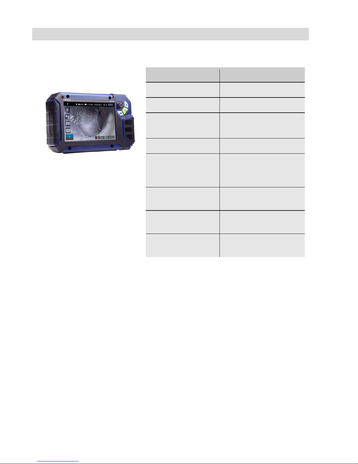
Fig. 1: Monitor
Description
Data
Dimensions housing
0.3 x 0.2 x 0.1 inch
Weight
1.9 lb
TFT display
7"/ 16:9 format
1280 x 800 pixel
Charging cable
USB-C 5 V/3 A
Power supply
3.7 V,
11400 mAh rechargeable Li-Ion battery
Battery operating
time
Up to 4 h (battery status
in display)
Operating Tempera-
ture
32 - 104 °F
Storage Tempera-
ture
- 4 – 122°F
Page 10
Technical Data
10
3.2 Wöhler pan & tilt came-
ra head
Fig.
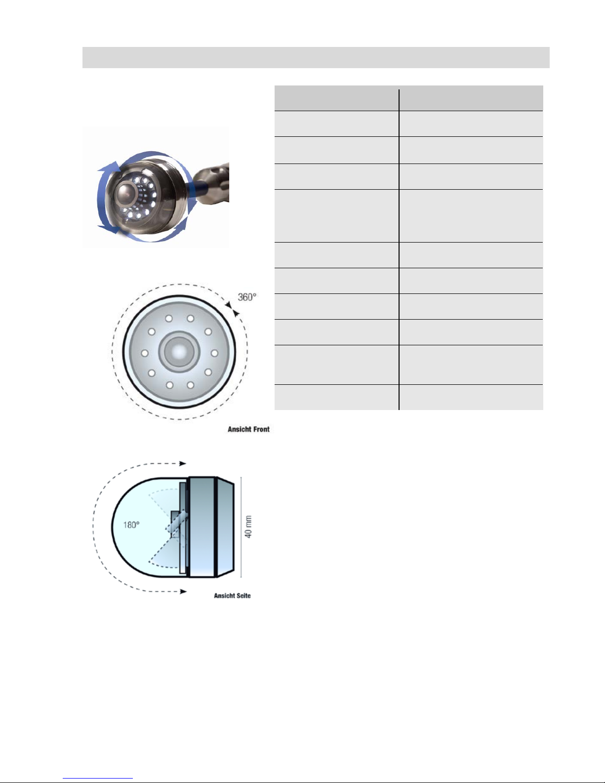
2: Pan & tilt camera head
Fig.
3: Pans through 360°
Fig.
4: Tilts 180°
Description
Data
Classification Type
½.7" COLOR CMOS
Focus distance
1 inch ... ∞
Light source
10 white LEDs
Protection
Waterproof to IP 67 (up
to 1 m depth for 30
mins.)
Dimensions
Diameter
Ø 1.5 inch
Shell length
2.2 inch
Total length
ca. 4 inch
Frequency of the
integrated emitter
9.2 kHz
Angle of detection
75°
Page 11
Technical Data
11
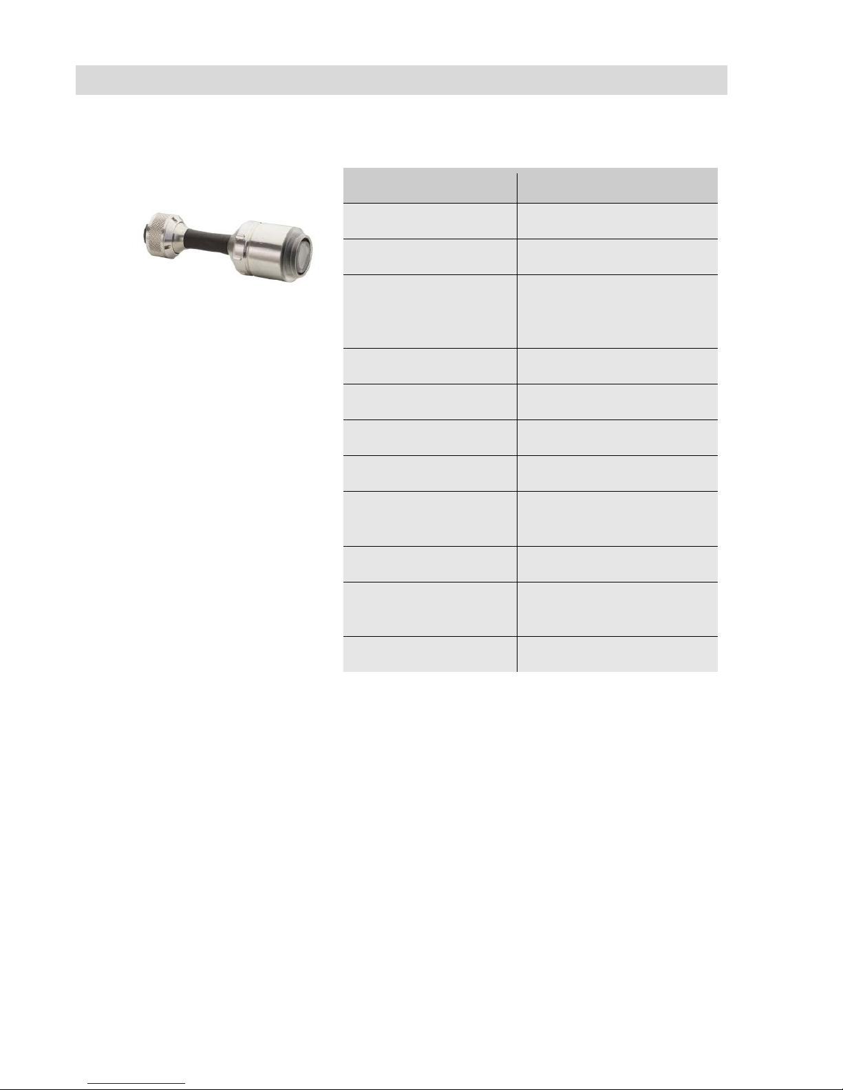
HD – Miniature Camera Head
Fig.
5: HD Miniature Camera Head
Description
Data
Classification Type
1/2,7" COLOR CMOS
Light source
10 white LEDs
Protection
Waterproof to IP 68 (up
to 30 m depth for 30
mins.)
Dimensions
Diameter
Ø 1 inch
Shell length
1.3 inch
Total length
ca. 3.2 inch
Frequency of the
integrated emitter
9.2 kHz
Angle of detection
150°
Operation
temperature
0 … 40 °C
Storage temperature
– 20 … 50 °C
Page 12
Technical Data
12
3.3 Cable
Description
Data
Length
65 ft., 0,02 ft. Ø
3.4 Storage
Description
Data
Memory
If you are using a
memory card other
than the one included
in the scope of supply,
you must format it on
a PC before using it
with the camera. FAT
32
Max.
32 GB
Technology
SD or SDHC,
maximum speed 10
Record Capacity
Approx. 3 GB/h
Video Resolution
1280 x 720 HD, max.
25 fps.
Video format
AVI (H264)
Page 13
Monitor
13
4 Monitor
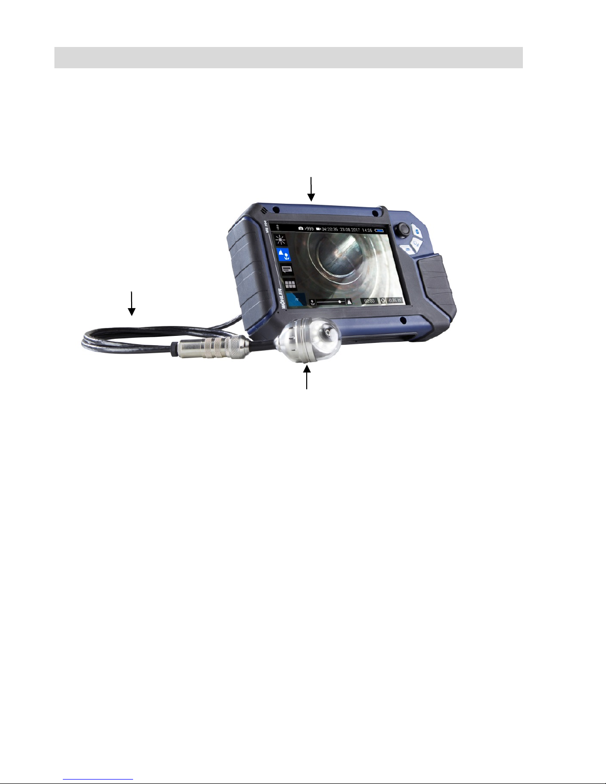
Fig. 6: Wöhler VIS 700 HD-Cable Camera
Camera head
Monitor
Camera cable, 65 ft.
Page 14
Monitor
14
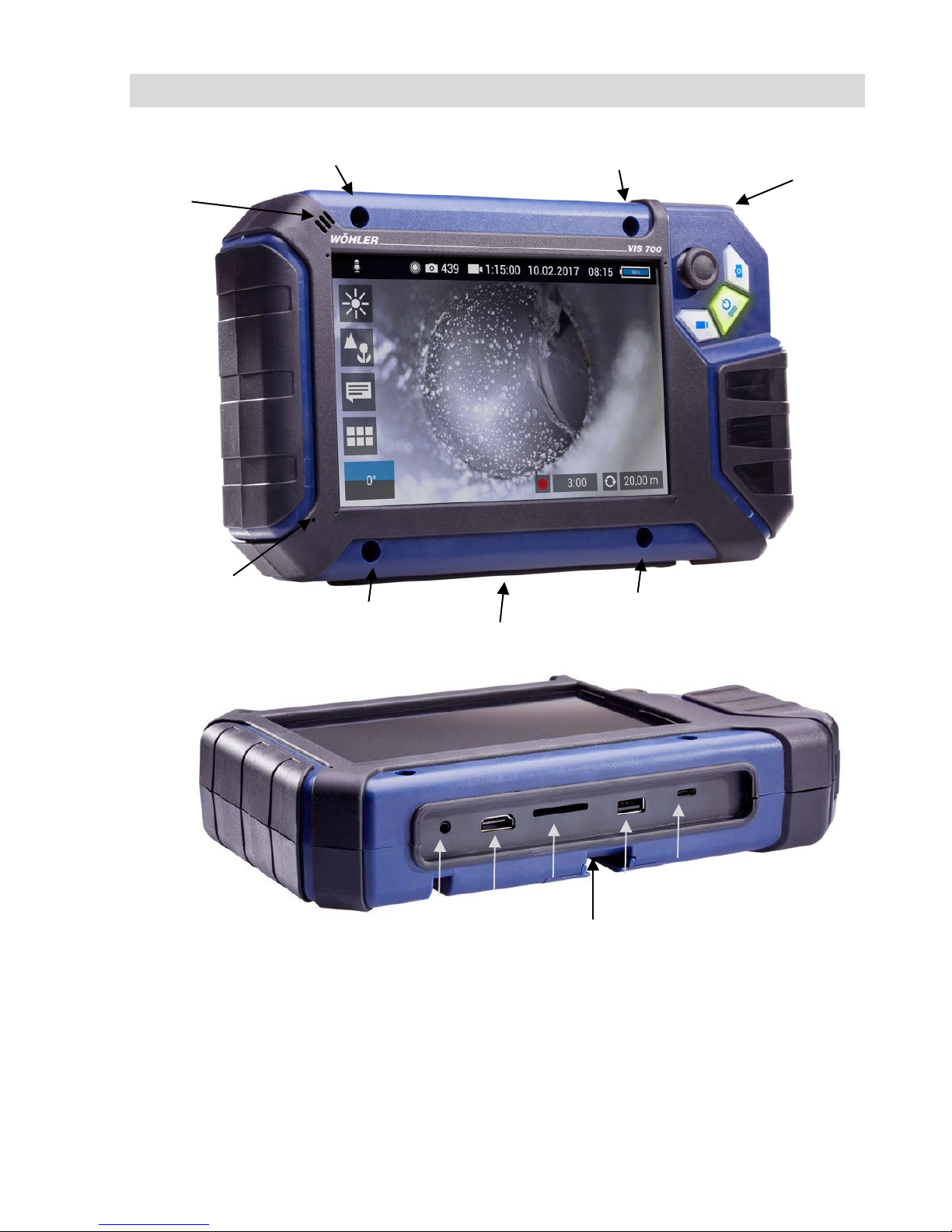
Fig. 7: Monitor
Fig. 8: Bottom side of the monitor with USB and SD card slot
1 1 1 1 2 3 6 7 8 9 10 4 11
5
Page 15

Monitor
15
Legend:
1
Fixing holes for glare protection
2
Handle, in the picture inserted in the slot of the housing
3
Bottom side of the monitor with terminal strip
4
Loudspeaker
5
Microphone
6
CTIA standard connection for headset with headphone and microphone
7
HDMI connection for external monitor
8
SD Card slot
9
USB port for stick
10
USB port for charging cable
11
Notch for placing the monitor on the connecting rail of the cas e
Page 16
Connecting the camera cable and camera head
16
5 Connecting the camera cable and camera head
5.1 Connecting the camera cable
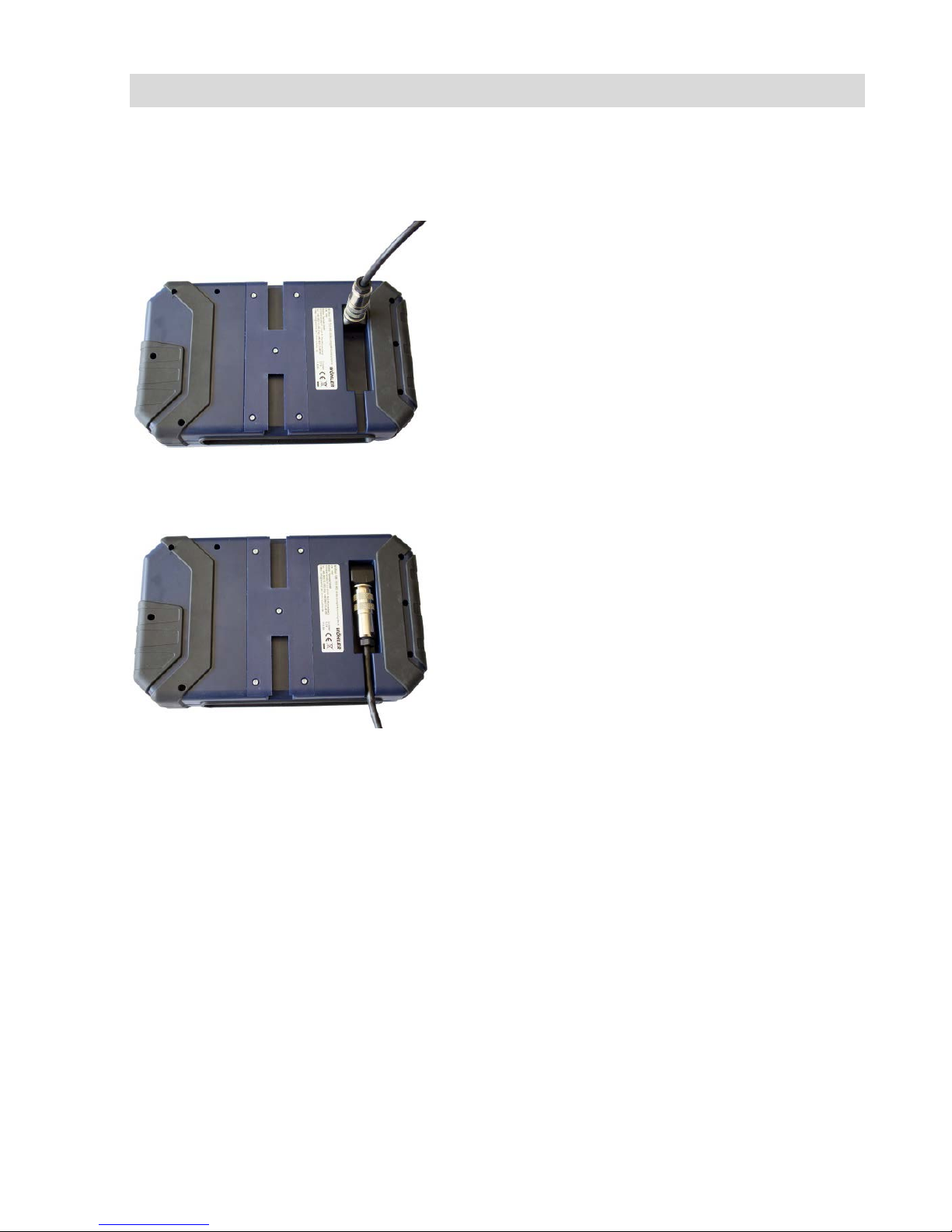
Fig. 9: Camera cable connection
• Flip up the five-pole female connector located
on the rear of the monitor.
•
Insert the male connector of the camera cabl e
or rod into the female connector, then tur n the
locking ring clockwise to secure the connection.
Fig. 10: Camera cable fed through guide
• Move the female connector with connected
cable or rod to a suitable working position:
•
Feed the cable through the guide, if you wish
to put down the monitor.
Page 17
Connecting the camera cable and camera head
17
5.2 Connecting the camera head
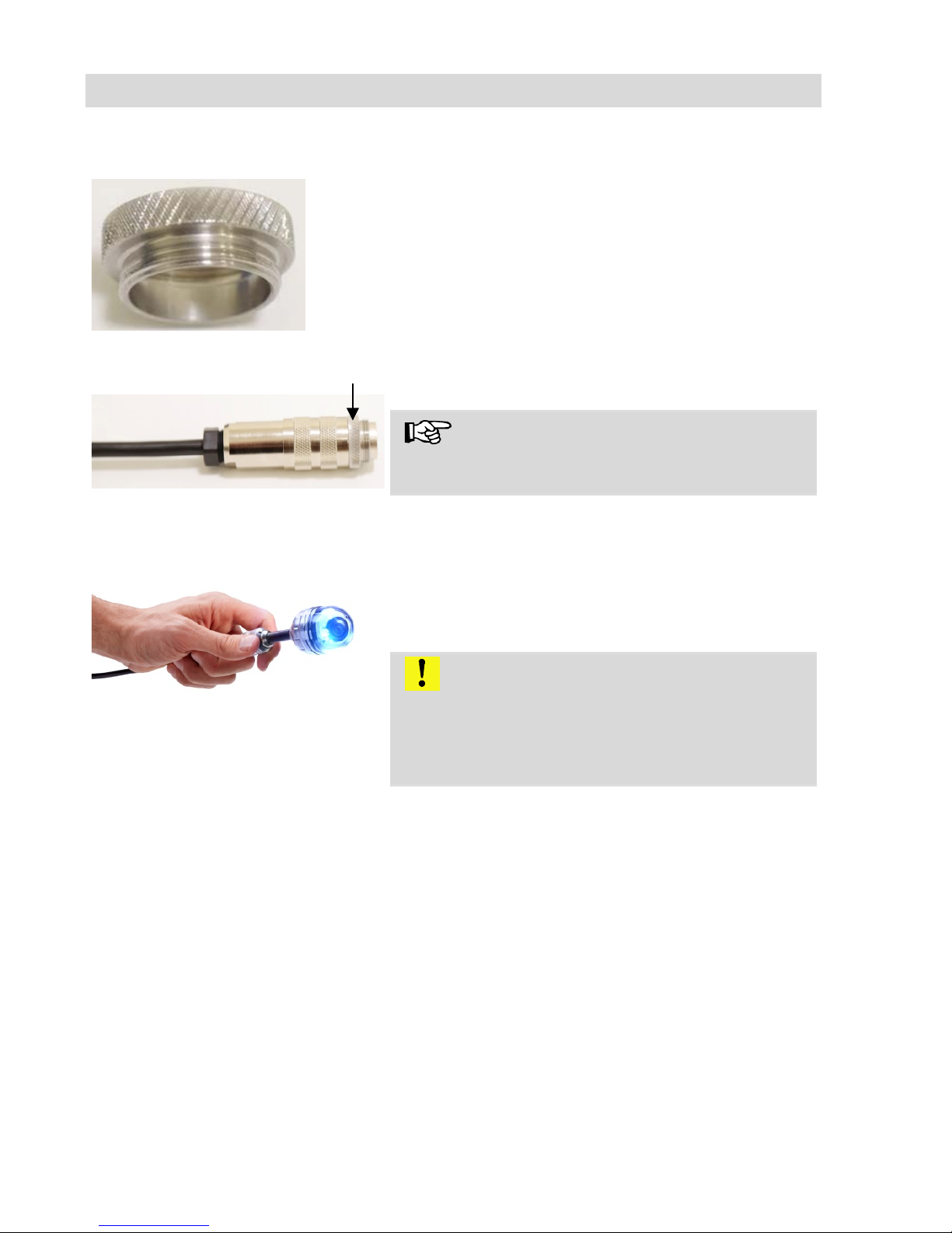
Fig
. 11: Adapter ring
• Check whether the adapter ring is plugged
onto the connector for the camera head. If not,
plug it on.
Fig
. 12: Connector for the camera head
with adapter ring (marked with arrow)
Note!
When the device is delivered, the adapter ring is
plugged onto the connector.
Fig
. 13: Wöhler camera head Ø 40 mm
connected to the camera cable
Insert the male cable connector into the five-pole
female connector of the camera head, then turn
the locking ring clockwise to secure the connection.
CAUTION!
The connection is only waterproof when the connectors are joined together properly.
Tighten the locking ring with your hand; never use
pliers!
Page 18
Starting up
18
6 Starting up
6.1 Activating the bat-
tery
If the camera system cannot be switched on dur-
ing initial operation, you have two options for activating the battery:
• Connect the monitor to the mains via the pow-
er supply unit. Switch on the camera system.
Afterwards, the camera can also be switched on
without being connected to the power supply.
or
• Carry out a reset 1, see chapter 15.1
6.2 Charging the
rechargeable battery
WARNING!
Danger of death by electrocution!
Never touch a mains plug with wet hands!
Do not expose the power pack to moisture!
Never pull the cable to remove the power pack
from the socket outlet - it could rip out the cable!
Operate the power pack only when the mains
power supply is the same as the voltage stated on
the rating plate!
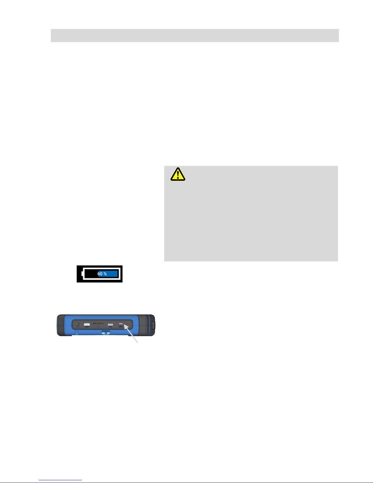
Fig. 14: Battery charge icon 60%
A battery charge icon is on the right of the icon
ribbon. The charge level is displayed in either blue
or orange (≤ 20%).
Recharge the rechargeable battery if the charge
level is displayed in red (≤ 10%).
• To charge the battery, connect the monitor to
the mains using the USB power pack included
in the scope of supply.
• To do so, insert the USB C connector into the
USB port on the bottom of the monitor.
Fig. 15: USB port indicated by an
arrow
Page 19
Handling the monitor
19
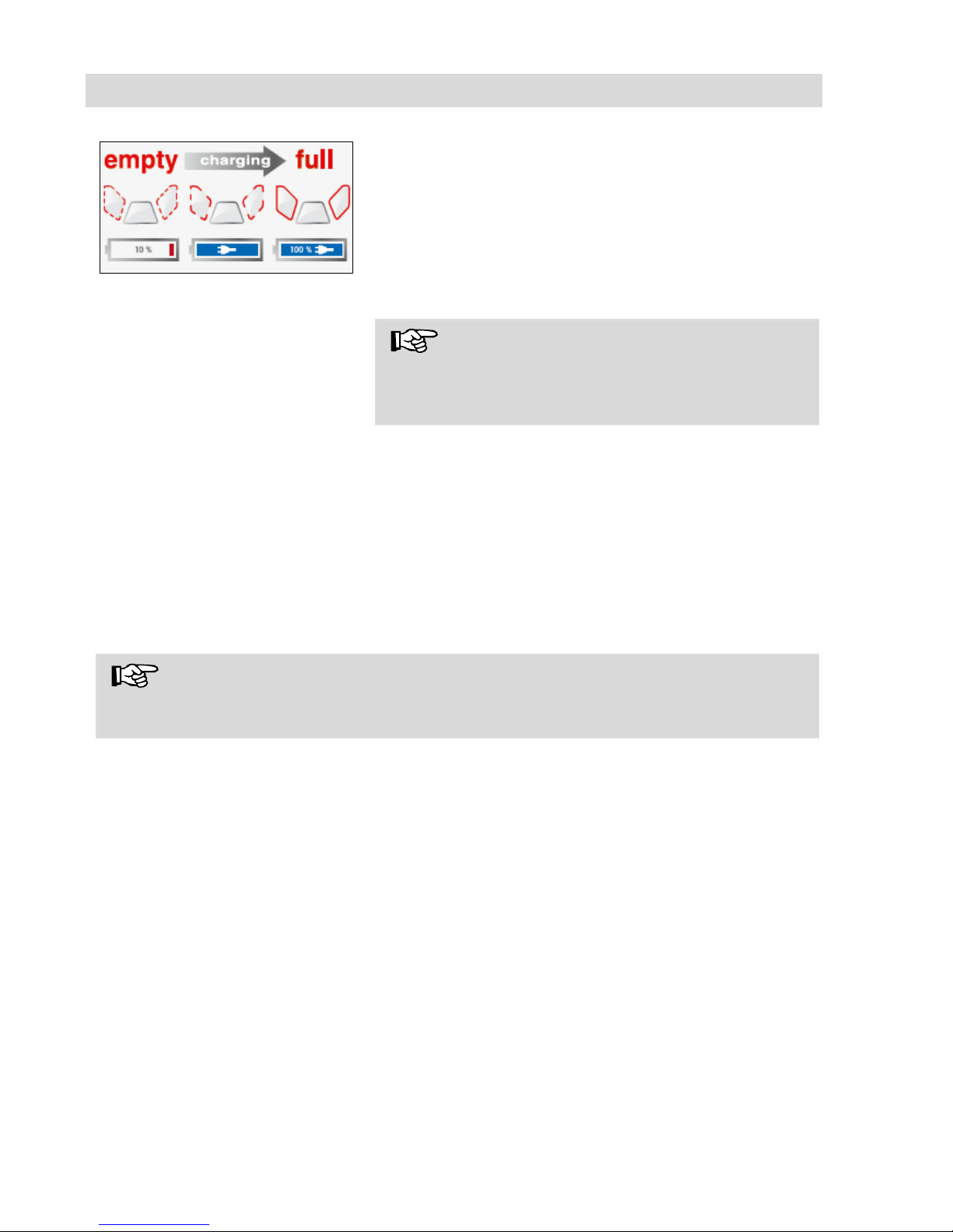
Fig. 16: Keys and charge level
indicated when charging
When the camera system is switched off the im-
age and video keys flash red during the charging
process.
The image and video keys light up red when the
battery is fully charged.
The camera system remains fully functional during
the battery charging process.
NOTE!
If possible, recharge the battery when the camera
system is switched off. This increases the operational lifetime of the rechargeable battery.
The keys will not flash if the battery is recharged
with the camera system switched on. A connector
symbol is displayed in the rechargeable battery
display.
7 Handling the monitor
NOTE!
The monitor image can rotate so that the joystick on the monitor can be operated
with the left or right hand, depending on the situation or personal preference.
Page 20
Handling the monitor
20
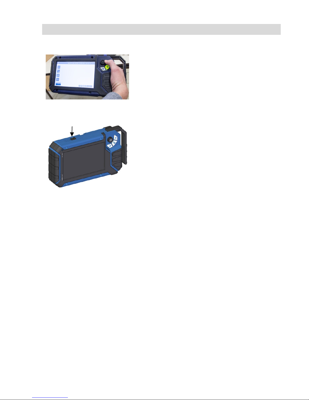
Handle
Fig. 17: With the handle pulled out
it is possible to hold and operate
the monitor with one hand.
It is possible to pull out a handle to allow you to
hold the monitor in your right hand and operate the
joystick with your right hand at the same time.
Fig. 18: Push button for pulling out
the handle marked with arrow
• To pull out the handle press the black pushbut-
ton on the top of the monitor and slide the
handle to the right at the same time.
Glare Protection
• Remove the Glare Protection from of the case
lid. It is located in the compartment behind the
lower part of the Short Guide.
• Insert both pins of the Glare Protection into the
corresponding fixing holes immediately above
or below the display to suit your working position. Magnets at the ends of the pins ensure a
stable hold.
Page 21
Keys and their functions
21
8 Keys and their functions
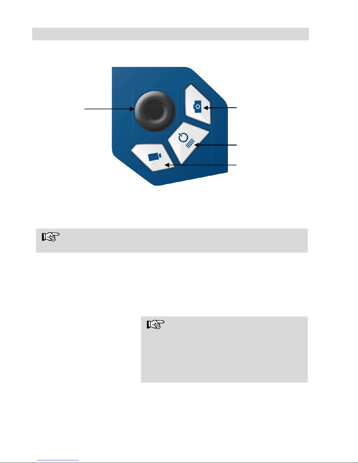
Fig. 19: Monitor keys
8.1 On/Off key
NOTE!
The ventilation fan works at irregular intervals when the camera is in operation.
Switching on the system
• When the system is switched off, press and
hold the ON/Off key for approx. one second.
The ON/Off key then lights up green, the image and video keys light up blue.
After approx. five seconds the LEDs light up on the
camera. The Home screen is displayed followed by
the camera image.
NOTE!
It is possible to turn the monitor through 180°. The
icon and information ribbons in the monitor are
automatically aligned according to the monitor position. It is also possible to turn the viewing position of the screen by slightly turning the monitor.
Switching the system off
• Press and hold the On/Off key for approx. two
seconds until the system switches off .
On/Off key/
Menu key
Image key
Video key
Joystick
Page 22
Keys and their functions
22
Calling up the menu
• When the system is switched on briefly press
the ON/Off key to display the menu.
• Briefly press the ON/Off key again to hide the
menu.
8.2 Video key
• To begin recording a video, briefly press the
video key.
• To stop recording the video, briefly press the
video key again.
A red dot is displayed in the information ribbon of
the display when a video is being recorded. In
addition, the video recording time is also displayed
in the information ribbon.
NOTE!
The camera will only record a video when a
memory card is installed. The camera will automatically stop recording, if the memory card is removed.
NOTE!
It is not possible to save the position indicator or a
comment when recording a video.
If you require this information, it is recommended
that you capture an image while recording the video. In the photo all information is shown as graphical elements.
Record time
NOTE!
After 30 minutes the camera will automatically stop
recording a video. If the video has to be recorded
over a longer period of time, the user has to start
recording again by pressing the video key after 30
minutes.
NOTE!
The minimum record time is 10 seconds. Even if
the user tries to stop the record before, the camera
will stop recording after 10 s only.
Page 23

Keys and their functions
23
8.3 Image key
• Press the image key briefly to capture an im-
age.
It is possible to capture an image while recording a
video.
NOTE!
The camera will only capture an image when a
memory card is installed.
8.4 Joystick
Tilts through 180°
• To tilt the camera head move the joystick back
and forth.
Pans through 360°
• To pan the camera head move the joystick left
or right.
Page 24
Display elements
24
9 Display elements
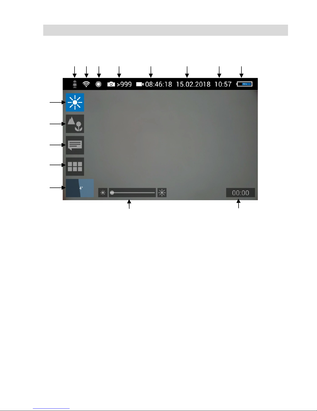
Legend:
1
Brightness control
2
Focus control
3
Comment function
4
System menu
5
“Horizon” with tilt and pan angle display / Home function
6
“Brightness” slider (the “Focus” slider can also be displayed here)
7
Video recording time
8
Microphone on/off
9
WLAN active
10
Locator
11
Number of possible images remaining
12
Remaining video recording time
13
Date
14
Time
15
Remaining battery charge
1 2 3 4 5 8 10
11
12
14
15 6 7 9 13
Page 25
Displayed position of the camera head
25
10 Displayed posi-
tion of the
camera head
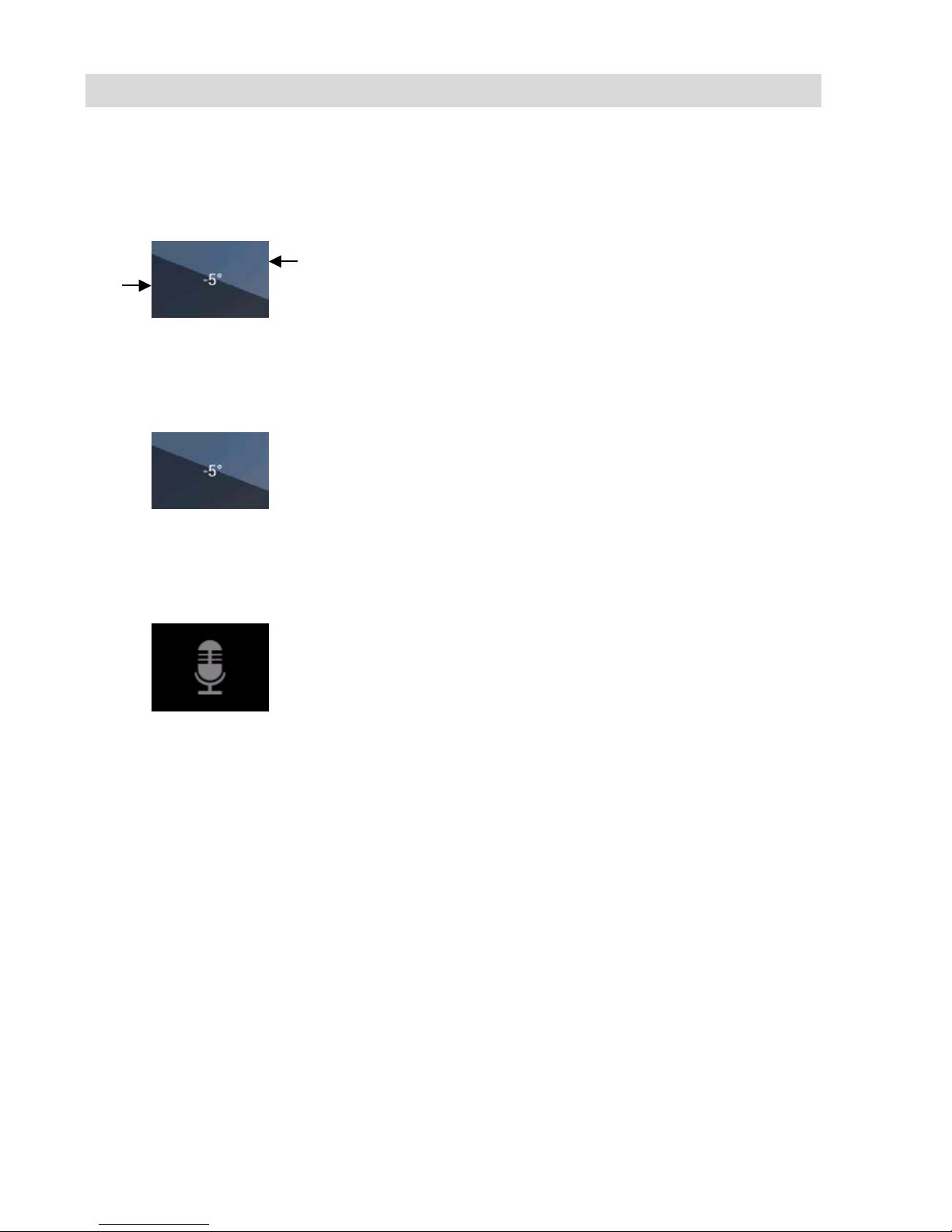
Fig. 20: Horizon icon including
degree display
The horizon icon indicates the downward gradient
of the pipe.
Example:
- 5° corresponds to a downward gradient of 5°
(+ 5° corresponds to an upward gradient of 5°)
11 Home function
Fig. 21: Tap the horizon icon to
level the camera head
The Home function makes it possible to align the
camera head in a straight position, so that the
camera faces “straight ahead” and the tilt and pan
angle display is depicted parallel to the ground
below.
• To activate the Home function tap the horizon
symbol in the display.
12 Voice recording
Fig. 22: Microphone icon
The Wöhler VIS 700 can record a voice recording
for each video. The microphone must be activated
before recording.
• Tap the microphone icon to activate the micro-
phone.
The microphone is located at the bottom left of the
monitor, see Fig. 7, part 5.
• Tap the microphone icon again to deactivate
the microphone if you do not want the sound to
be recorded during video recording.
Heaven
Earth
Page 26
Live menu
26
13 Live menu
Via the live menu, settings can be made on the ca-
mera system.
• To display the live menu, briefly tap the
On/Off/Menu key when the system is switched
on.
• To hide the menu, briefly tap the On/Off/Menu
key again.
All menu settings are made using the touchscreen.
As soon as a slider appears in the display it is possible to configure the settings via the touchscreen or
using the joystick. That is the case with the Focus
menu and the Brightness menu.
13.1 Brightness menu
Fig. 23: Brightness menu icon
In the Brightness menu it is possible to regul ate
the light intensity of the camera head LEDs.
• Tap the menu icon “Brightness”.
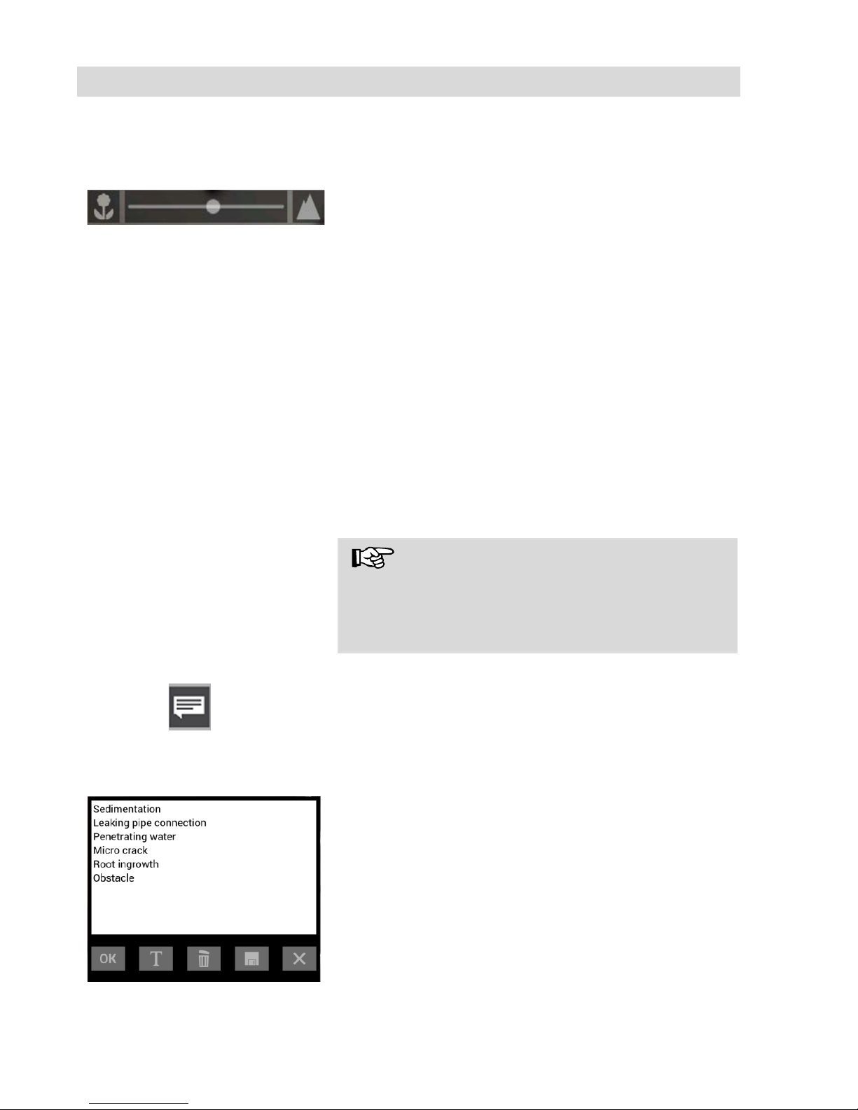
Fig. 24: Brightness slider
• To increase or decrease the brightn es s
- slide the dot on the slider using the joystick in
desired direction
or
- tap the sun symbol on the corresponding side
next to the slider or slide the dot on the slider
in the desired direction.
• To exit the Brightness menu press the joystick
or tap another menu in the display.
13.2 Focus menu
Fig. 25: Focus menu icon
NOTE!
The focus function of the Wöhler VIS 700 HD
camera is only active when the HD pan and tild
camera head Ø 40 mm is connected , not when
the HD miniature camera head Ø 26 mm is connected. The miniature camera head has a fixed
focus.
In the focus menu, you can set the sharpness of
the image area you are interested in. You can
adjust the focus using the touch screen or the joystick.
Page 27
Live menu
27
Adjusting the focus via
the touchscreen
Fig. 26: Focus slider
• Tap the menu icon “Focus” in the display to
call up the slider.
• To adjust the focus
slide the dot on the slider
or
tap the flower or mountain icon.
Adjusting the focus per
joystick
• To activate the focus function, briefly press the
joystick.
• Move the joystick left or right to adjust the
focus setting.
13.3 Comment function
Using the comment function it is possible to add a
written comment to an image. Images can then be
saved together with the comments. It is not possible to add a comment to an image after it has
been saved.
NOTE!
It is not possible to add a written comment directly
to a video. However, it is possible to capture an
image while recording a video. It is then possible
to add a comment to the image before saving it.
Add a comment
Fig. 27: Comment menu icon
• Tap the menu icon “Comment” in the display.
The comment list appears with ready-made comments.
Add a comment to the list of
comments
Fig. 28. List of comments
• To create a new comment tap the text icon T.
• Enter the new comment using the keypad.
• Tap OK to add the new comment to the list of
comments. The new comment is displayed
when the list of comments is called up again.
Page 28
Live menu
28
Add a comment to an image
• To add a comment to the image, simply select
the comment in the list and tap OK.
Delete a comment from the list
of comments
• To delete a comment from the list of com-
ments, select the comment in the list of comments and then tap the Recycle Bin icon. The
comment is no longer displayed when the
comment function is cal led up again .
• To delete a comment previously added to an
image, tap the comment to be deleted and
then tap the Recycle Bin symbol in the Comment menu.
Store the list of comments
• Tap the save icon if you want to save the cur-
rent comment list permanently.
The save icon will be colored blue for 2 seconds.
• If you exit the Comment menu without saving
your new comment, the new comment will no
longer appear in the list.
Delete a comment from the
image
• Select the comment in the image (not in the
comments list), and then tap the Recycle Bin
icon to delete the comment from the image.
Exit the Comment menu
• Tap the X icon to exit the Comment menu.
Page 29
Live menu
29
13.4 System menu
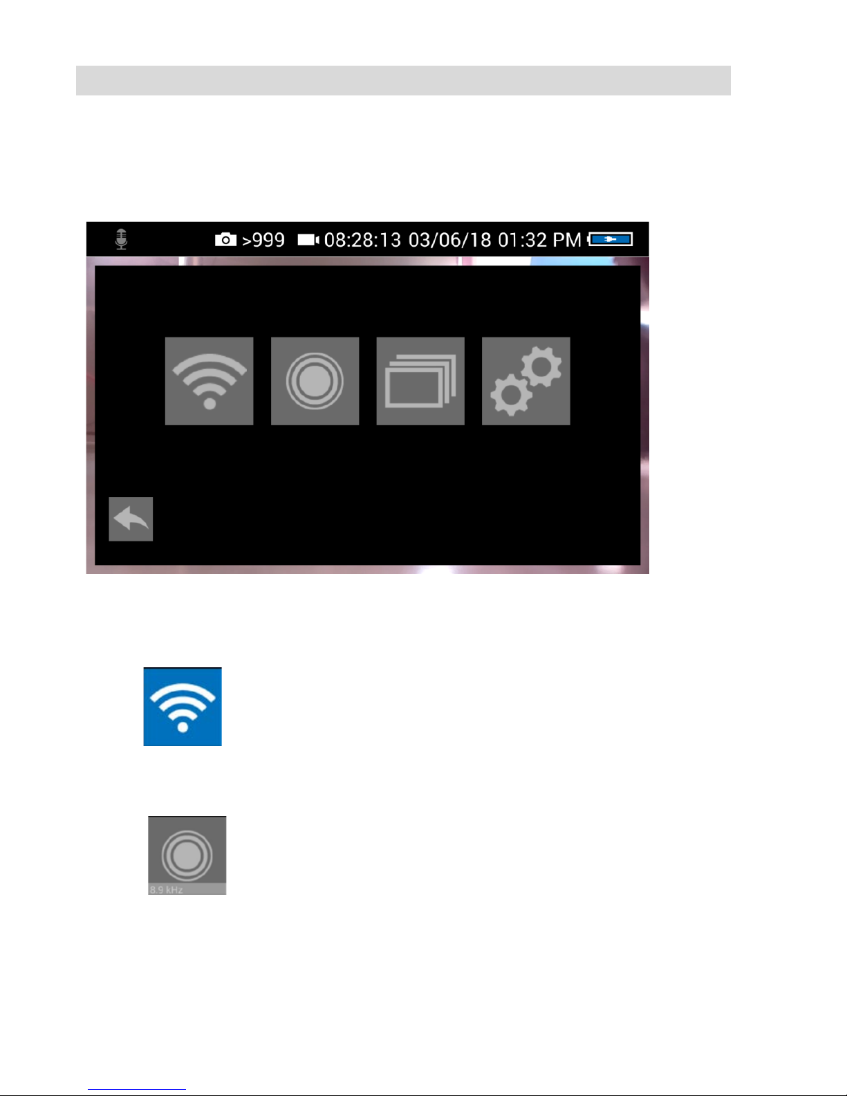
You can access the System menu via the following submenus:
WLAN, Location detection, Image and video gallery, Settings.
The active functions are highlighted blue, inactive functions are grey.
Fig. 29: System menu with submenus WLAN (1), Locator detection (2), Image and video gallery
(3) and settings (4)
13.4.1 Activate WLAN
Fig. 30: WLAN icon
This function is described in chapter 14.
13.4.2 Locator
Fig. 31: Locator icon
• Tap the Locator icon to activate the locator
transmitter.
It is now possible to detect the camera head with
the Wöhler Locator 200.
1 2 3
4
Page 30
Live menu
30
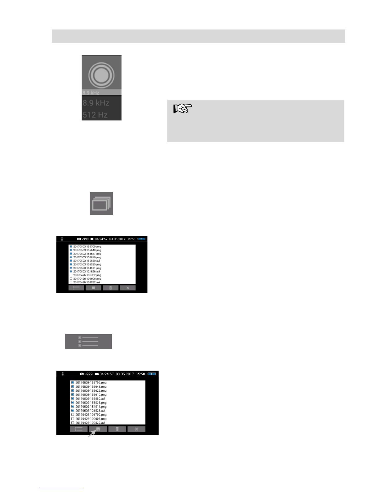
Fig. 32: Selecting the frequency
The transmission frequency of the connected
camera head is displayed below the locator icon.
• Tap on the transmission frequency, if you want
to change between 9.9 kHz and 512 Hz
NOTE!
The camera consumes less power when the
transmitter is switched off. Ho wever, in this case it
will not be possible to locate the camera head.
13.4.3 Saving and delet-
ing images and
videos
Fig. 33: Image and video
gallery icon
Fig. 34: Image and video
gallery
The Picture and Video Gallery displays all the pic-
tures and videos you have taken. The respective
file name consists of the date and time of the recording.
Mark all files
Fig. 35: Lists icon
• Tap the Lists icon to highlight or deselect all
files.
Save files to USB drive
Fig. 36: Image gallery with highlighted files; the Save icon is
indicated by an arrow.
• Insert the USB drive into the monitor.
• Select the check boxes next to the files to be
saved. The check boxes will then be highlighted blue.
• Then tap the Save icon.
A dialog box opens to save the files to the USB
drive.
Page 31
Live menu
31
Delete files
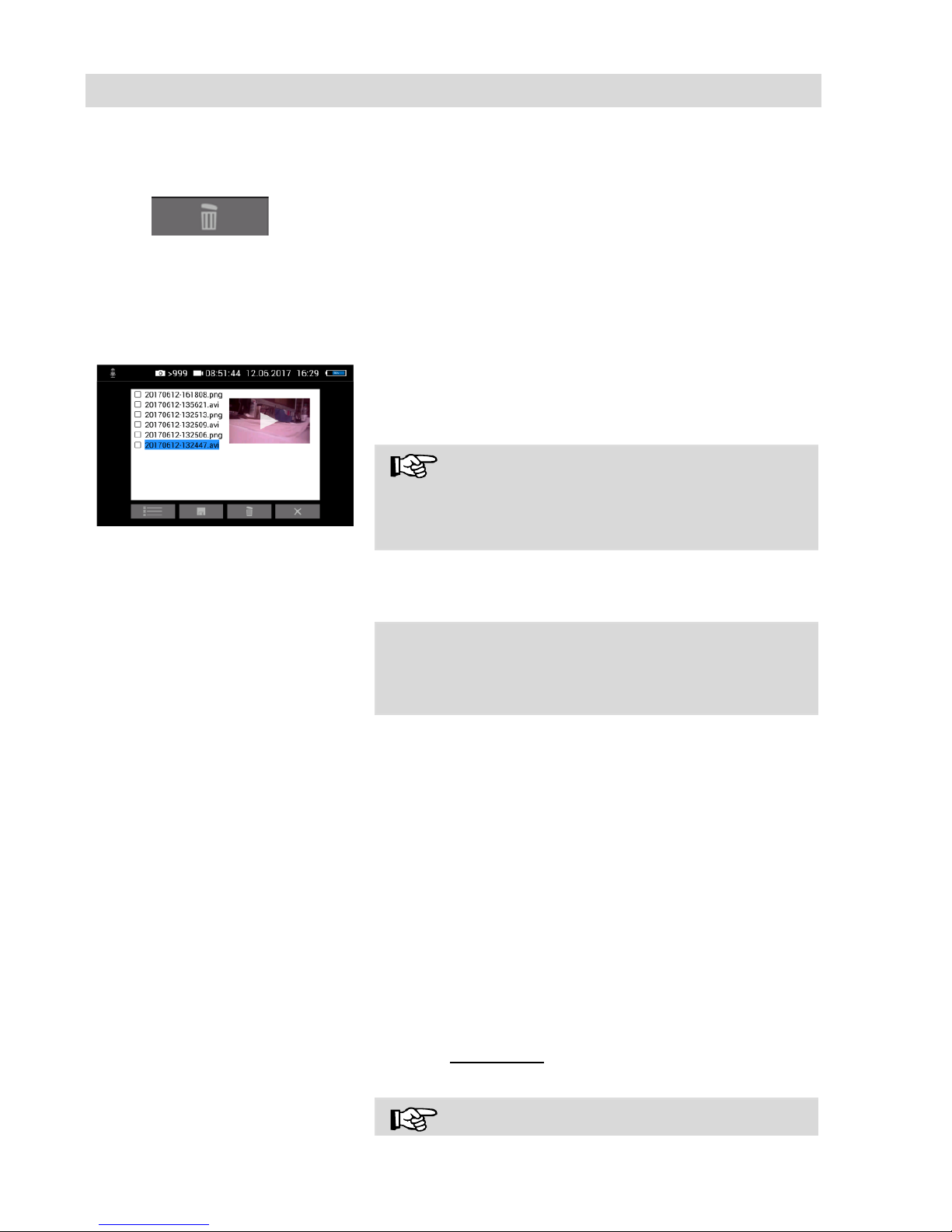
Fig. 37: Recycle Bin icon
• Select the check boxes next to the files to be
deleted. The check box next to a selected file
is highlighted blue.
• Then tap the Recycle Bin icon.
13.4.4 Display images
and videos
Fig. 38: Preview selected video
• Tap a file name in the Image and Video Gal-
lery.
An image or video preview is displayed next to the
file list.
• Tap Preview. The image or video is displayed.
NOTE!
Depending on the size of the video file it can take
several seconds for the video to load before it is
ready to play.
To return to the gallery, tap the image icon again
or tap the Close icon in the video.
How to playback videos on a
PC
NOTE!
During video playback, the date, time and meter
count are always displayed in the video , regardless of which media player is used.
There are two options to transmit images and videos from the camera to a PC.
• Save the image and video files to a USB drive
(see Fig. 36) and then load them onto the PC.
• Remove the SD memory card from the monitor
(see Fig. 8: .) Insert the memory card into the
card slot of the PC and copy the image and
video files onto the PC.
You can playback a video on the PC using the
Windows Media Player or VLC Player once you
have saved the respective video file to the PC. If
you work with a Windows PC, the Media Player
will already be installed on the PC. The VLC Player is available to download free of charge from the
website www.vlc.de
NOTE!
Page 32

Live menu
32
Depending on the size of the video file it can take
several seconds for the video to load before it is
ready to play.
Exit the Image and Video
Gallery
Tap the X icon to exit the Image and Video Gal-
lery.
Page 33
Live menu
33
13.4.5 Settings
Note!
The settings made here are automatically saved and remain stored after the camera
system has been switched off and switched on agai n.
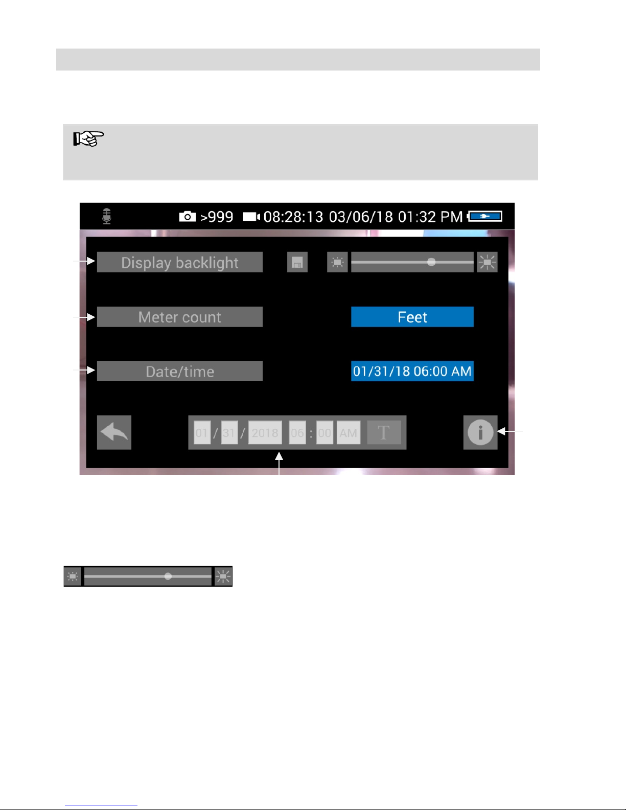
Fig. 39: Settings menu
1 Display Backlight
Here the display backlight can be adjus ted. (To
adjust the illumination of the camera head, see
chapter Fehler! Verweisquelle konnte nicht ge-
funden werden..)
When the camera is turned on, the display brightness is always set to 70%.
• To change the display brightness, tap on the
light icons next to the slide bar
or
• move the point on the slide bar.
It is possible to adjust the display brightness in 10
levels from 10% to 100%.
1 3 2 4 5
Page 34

Live menu
34
NOTE!
To reduce power consumption when the battery is
low, it is advisable to choose a low backlight.
2 Meter Count
There are 2 possibilities to display the meter
count:
0.00 m (Meter)
0.0 ft. (feet)
• Tap on the blue unit field to change the unit.
3 Date/Time
Here you can change the display of date and time.
The following possibilities exist:
USA:
Month/Day/Year
00:00 – 12:00 AM and 00:00 – 12:00 PM
GERMAN:
Day.Month.Year
00.00 – 24.00
INTERNATIONAL:
Year-Month-Day
00:00 – 12:00 AM and 00:00 – 12:00 PM
4 Updating the date and
the time
Here you can change the date and time. They
appear in the header of the display and as file
names of stored photos and videos.
• Tap the T icon next to the date and time. A
keyboard opens.
• Select the numeric keyboard.
• Fill in all fields one after the other with num-
bers and confirm with the tick.
The settings are saved automatically and are re-
tained after switching the camera off and switching
on again.
• Tap on the Info Button to enter the info menu.
Page 35
Live menu
35
13.4.6 Info menu
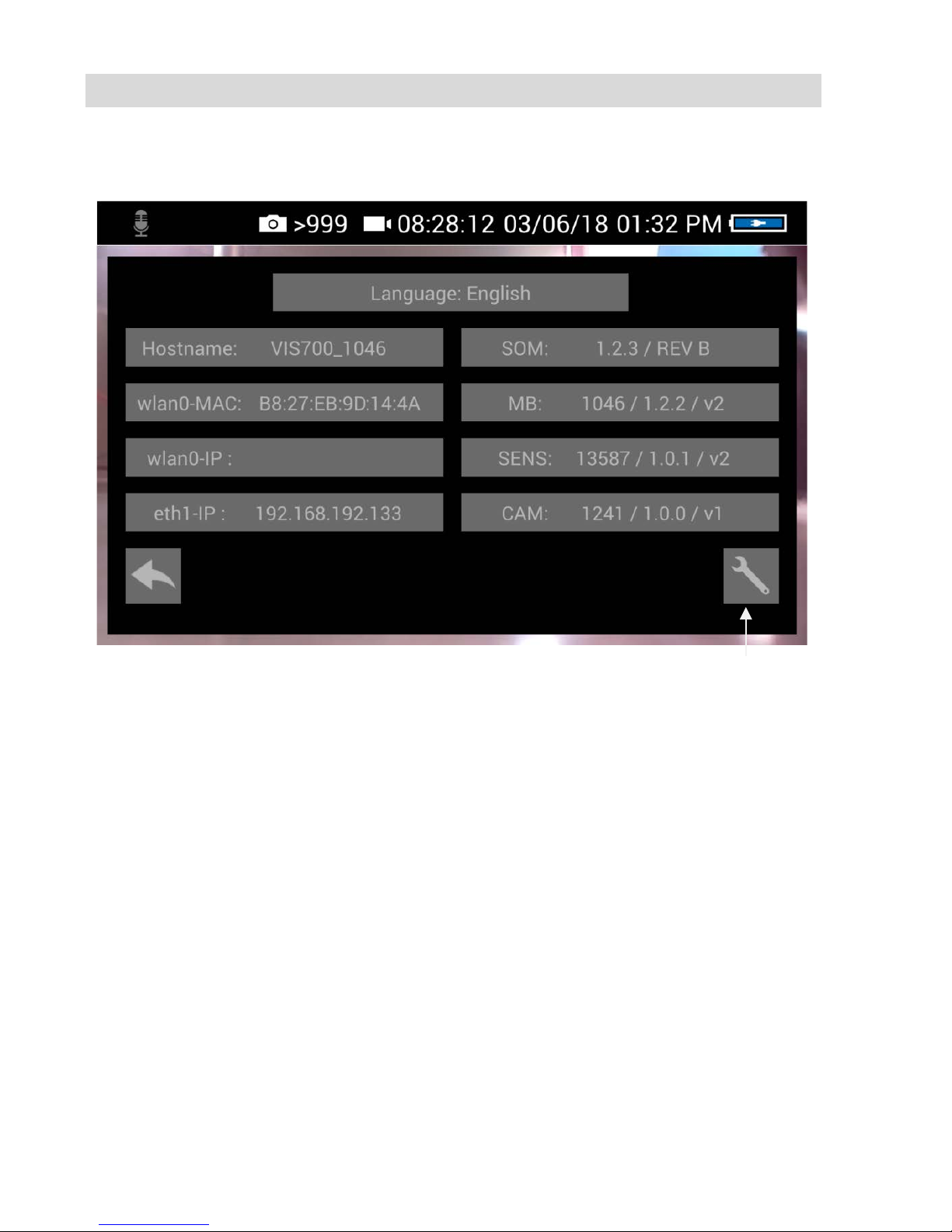
Fig. 40: Info menu
In the info menu under "Hostname" you will find
the serial number which is required for displaying
the images in a browser, see chapter 14 (transmission of the image files via WLAN), the language version, the wlanO-IP as well as software
and hardware versions for the service.
The user does not have to operated the service
button.
Servic button
Page 36
Transmission of image files via WLAN
36
14
Transmission of image files via WLAN
There are 2 ways for a live transmission of images and videos:
1. Access Point: the Wöhler VIS 700 establishes its own WLAN network.
2. Client: You dial into a stationary WLAN network with the Wöhler VIS 700
and your mobile device or laptop.
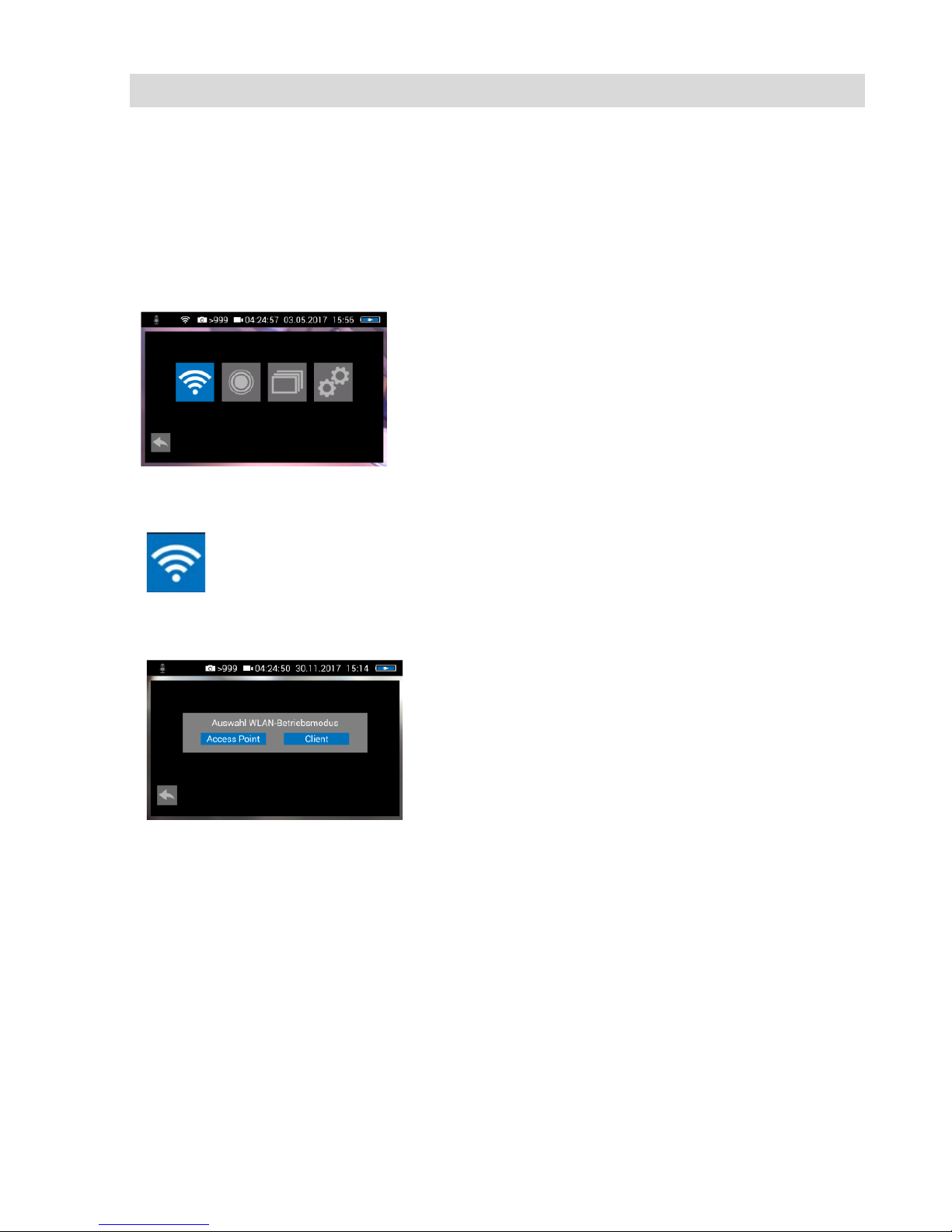
Fig. 41: system menu with activat-
ed WLAN icon
• Open the System menu, see chapter 13.4.
Fig. 42: WLAN icon
• Tap on the WLAN Icon, to activate the WLAN
function of the camera system.
The camera will now search for the available networks.
Fig. 43: Selecting the WLAN mode
• You will be prompted to select the WLAN op-
erating mode: "Access Point" or "Client".
Page 37
Transmission of image files via WLAN
37
14.1 Access Point: Transmission via a VIS 700-WLAN-network
When “Access Point” is selected, the Wöhler VIS 700 builds up its own WLAN network, via which the image data can be transferred directly to a mobile device.
This method allows to view the live images on the Wöhler VIS 700 monitor, while a
colleague standing at the other end of the tube, can watch the live videos on his
mobile device.
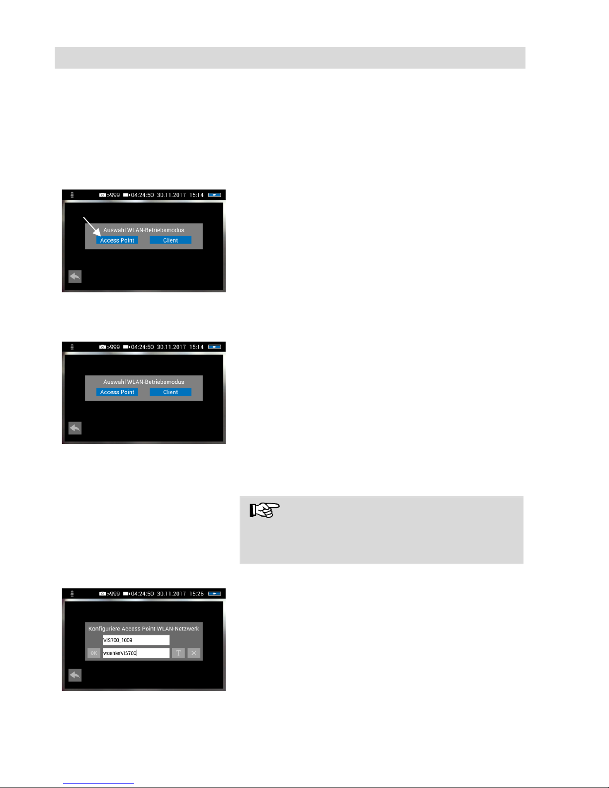
Fig. 44: „AccessPoi nt“
• Select “Access Point”
The display shows the network name of the Wöh-
ler VIS 700 and the password you need to connect
your mobile device.
The network name is composed as follows:
VIS700_serial number of the camera.
The default password is:
woehlerVIS700
It is possible to change the network name and the
password.
NOTE
If you change the network name, you can use your
own company name as the network name, for example.
Fig. 45: Changing the password
• To change the network name or password, tap
the corresponding field and then tap the textbutton T.
A keyboard will appear on screen.
• Make the appropriate changes.
• Tap OK to save the changes.
Page 38
Transmission of image files v ia WLAN
38
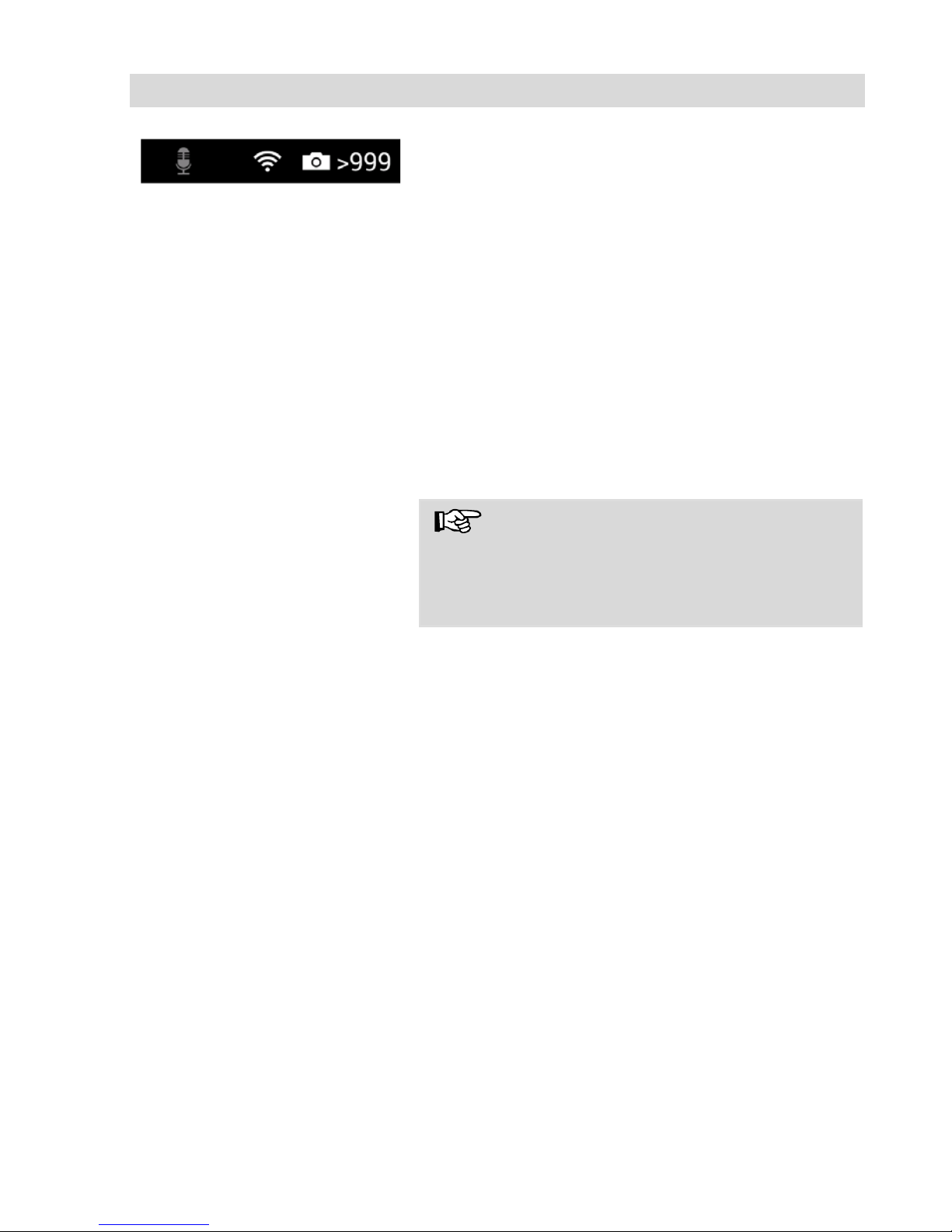
Fig. 46: WLAN icon in t he icon
ribbon
The WLAN icon is displayed in the icon ribbon of
the display until the WLAN function is deactivated.
• To deactivate the WLAN function, tap the
WLAN icon again in the System menu.
Establishing a connection to a
mobile device
• To establish a connection between the camera
and the mobile device, proceed as follows.
• Access the WLAN settings of your mobile
device.
• Select the network VIS700_[serial number, 4
digits] or the network name that you have
chosen
• Enter the password. The password is
woehlerVIS700 or the password that you
have chosen. Note the upper and lower case
letters.
NOTE!
As long as your mobile device is connected to the
VIS700 network, you will not be able to connect it
to the Internet. Therefore, the warning message
"Internet not available" appears.
• Wait until the Wöhler VIS 700 establishes
contact with your mobile device.
• Open any browser on your mobile device
(Chrome, Internet Explorer, Firefox etc.)
• In the address bar of your browser enter:
http://VIS700_[serial number, 4 digits]
The camera image will now be shown on the display
of your mobile device. Changes made to the focus
and brightness settings in the camera menu will
also change the image shown on your terminal
device.
Page 39
Transmission of image files via WLAN
39
14.2 Client: Using an existing WLAN network
In the “Client” mode, you dial into an existing network both with the Wöhler VIS 700
and with a mobile device or a WLAN-capable PC or Laptop. This way, live image
transmission from the camera to the mobile device/laptop is even possible over a
certain distance. This possibility can be interesting in industrial plants, for example.
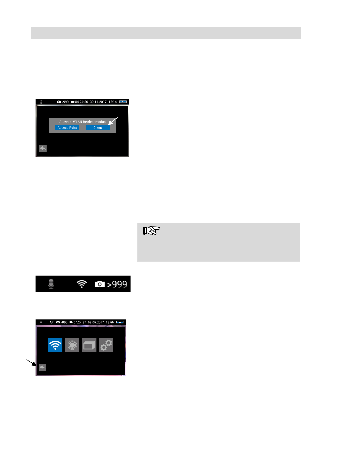
Fig. 47: Client
• Select “Client”.
All available networks will appear in the camera
display.
• Select the network.
• Enter the password of your network.
• Confirm with OK.
NOTE
The password will always be saved so that you do
not have to enter it the next time you log on to the
same network.
Fig. 48: WLAN-Icon in the header
After a successful connection , t he WLAN icon will
appear in the top bar of the display. The WLAN
button in the system menu will be highlighted in
blue until the WLAN function is deactivated again.
Fig. 49: System menu with activated WLAN button
• Tap the arrow button to exit the system menu.
Page 40
Transmission of image files via WLAN
40
Connection to a mobile de-
vice or laptop
• Proceed as follows to establish the connection
between the camera and the mobile device or
laptop.
• Open the WLAN settings of your mobile de-
vice.
• Select the same network that you dialed into
with the camera.
• Enter the password of your network.
• Open any browser on your mobile device or
laptop (Chrome, Firefox, Internetexplorer etc.).
Since the settings of mobile devices are different,
two procedures are described below. If option 1
does not work, proceed with option 2.
Option 1
• Enter the following address in the address bar
of the browser of your mobile device:
http://VIS700_[serial number, 4 digit]
NOTE
You can find the serial number on the sticker on
the back of the monitor or in the settings menu
(System menu>Settings) under "Hostname".
The Camera-picture will now appear on the screen
or your mobile device or laptop. Focus and brightness settings made via the menu on the camera
also affect the picture on the mobile device.
Option 2
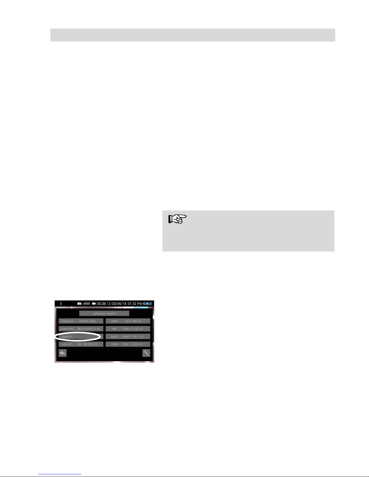
Fig. 50: Settings menu - wlan0_IP
is marked
• If your mobile device did not connect suc ce ss-
fully to the camera, proceed as follow s:
• Open the settings menu of the Wöhler VIS 700
(system menu > settings). In the left column
you will find the wlan0-IP.
• Enter the wlan0-IP in the address bar of your
browser. (without http, only the digits and
dots!)
The camera image will now appear in the display of
your mobile device. Focus and brightness settings
made via the menu on the camera image will also
affect the image on the mobile device.
Page 41
Faults
41
15 Faults
15.1 Reset
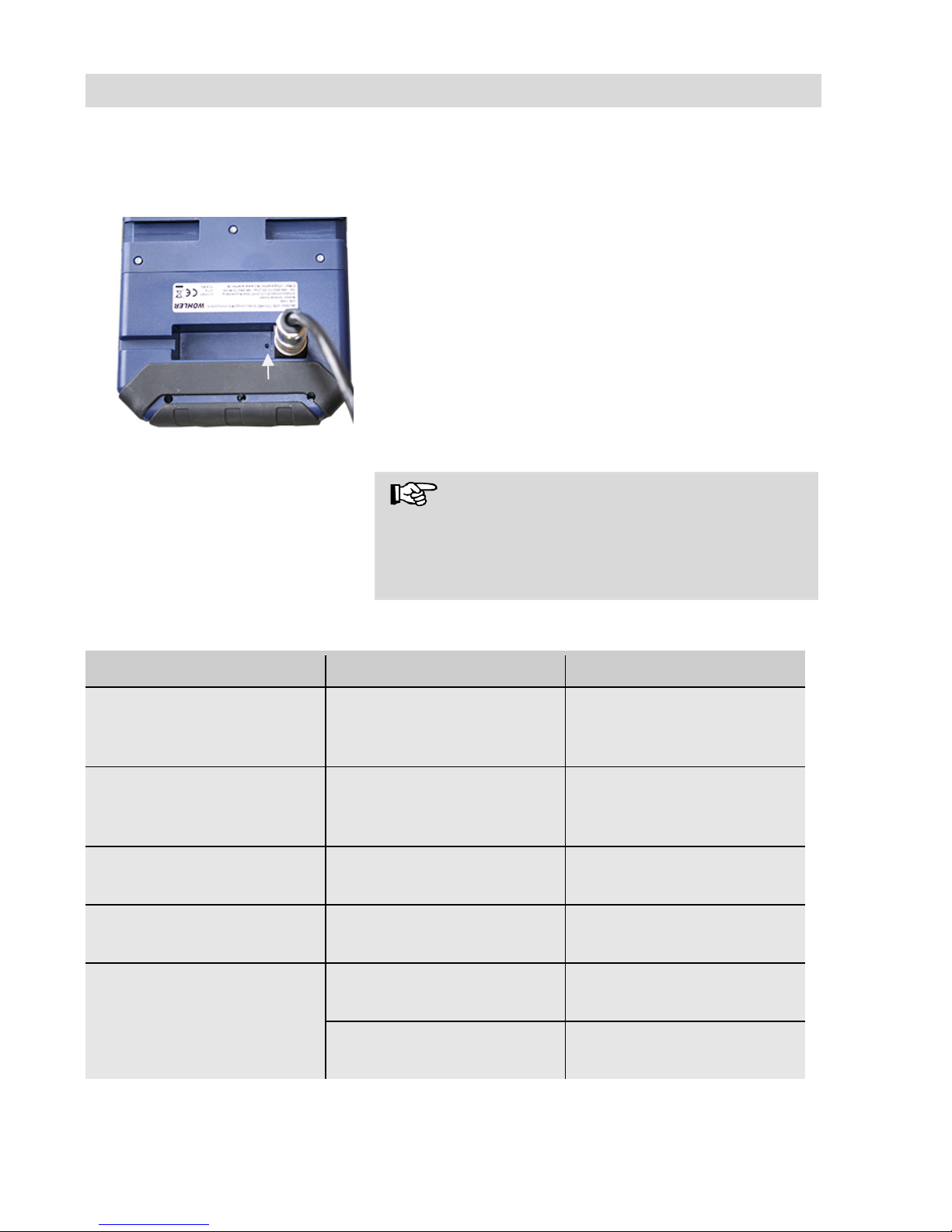
Fig. 51: Reset hole indicated by an
arrow
It is possible to rectify certain malfunctions by initi-
ating a reset operation. The reset hole is located
on the rear of the monitor next to the camera connection port, see Figure oppos ite.
• Reset 1: Insert a thin object, for example a
straightened paper clip, into the reset hole and
press for 2-3 seconds. All buttons should then
light up.
• Reset 2: If all buttons do not light up after 2-3
seconds, insert a thin object into the reset hole
and press for approx. 15 seconds. All buttons
should then light up.
NOTE!
Depending on the type of reset operation the reset
time (until all buttons light up) is between 2 and 15
seconds. The reset operation is successful when
all buttons light up.
15.2 Possible malfunctions
Fault description
Possible cause
Remedy
Image and video keys
flash rapidly when the
device is turned on.
Rechargeable battery is
flat.
Recharge the battery
Monitor and camera head
switched on. No image or
stuttering image replay.
Rod is broken.
Return the device for re-
pair.
Camera stops video re-
cording
No video signal, e.g. due
to a broken rod
If it occurs repeatedly,
return the unit for repair.
Blurred images
Plastic dome scratched.
Replace the plastic dome;
glass dome optional.
Camera system dead
Rechargeable battery is
flat.
Recharge the battery.
Device is faulty.
Return the device for re-
pair.
Page 42
Maintenance
42
16 Maintenance
16.1 Information on mainte-
nance
Proper operation of the Service Camera requires
regular maintenance. The following maintenance
works can be done by the user himself.
16.2 Replacing the dome of
the camera head
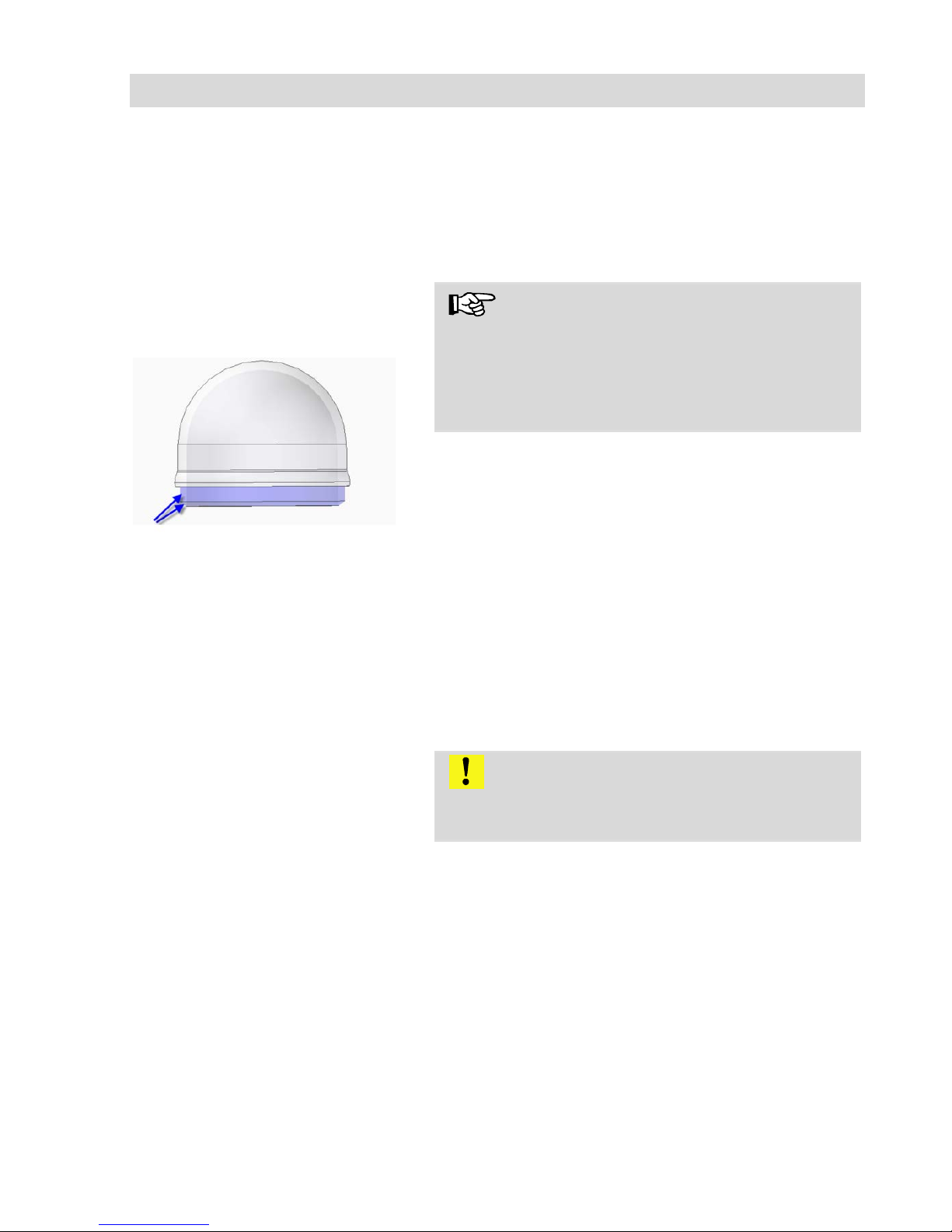
Fig.
52: Fitting the camera dome
NOTE!
The camera head is supplied protected by a plastic dome, which can be replaced if necessary, for
example, if it becomes scratched. It is optiona l to
fit this camera head with a glass dome for use in
dry working environments.
Smear the thread with silicone grease before fitting the new dome. When fitting the replacement
dome, make sure you engage all of the thread to
ensure it is properly tightened. Otherwise, it cannot be guaranteed that the camera head is
properly sealed, and malfuncti ons can oc cur as a
result of water and dirt ingress.
16.3 Camera head
• Only use soft, damp cloth to clean the lens.
Never use any cleanser.
16.4 Monitor
• Clean the monitor using a soft cloth.
16.5 Cleaning the cable
• Clean the cable with a damp cloth or spray it
with water.
Attention!
Make sure that no water gets into the connectors
or gets to the monitor.
Page 43

Guaranty and Service
43
17 Guaranty and Service
17.1 Guaranty
Each Wöhler VE 700 HD-Cable Camera will be
tested in all functions and will leave our factory
only after extensive quality control testing.
If used properly, the warranty period for the Wöhler VIS 700 will be 12 month from the date of sale.
Not covered by the warranty is the plastic dome
and SD card.
This warranty does not cover the freight and packing costs when the camera is sent to the factory
for repair.
Service by non authorized personnel or making
modifications to the analyzer voids any warranty.
17.2 Service
Excellent SERVICE is very important to us. There-
fore, of course, we are readily available to assist
you after the warranty period ends.
•
Send us the Camera and we will repair it and
return it to you with our package service.
•
Immediate help is provided by our technica l
staff over the telephone.
Page 44

Declaration of conformity
44
18 Declaration of conformity
The manufacturer:
Wöhler Technik GmbH
Wöhler-Platz 1, D-33181 Bad Wünnenberg
declares that the product
product name: HD-Cable Camera Wohler VIS 700
complies with the key safety requirements set down in the guidelines of the Council for
the Harmonization of the Legal Requirements of the Member States in relation to the
electromagnetic compatibility (2014/53/EU).
The following standards were availed of to evaluate the product in respect of the
elec-
tromagnetic compatibi lity :
EN 61326
-1:2013 / IEC 61326-1:2012
ETSI EN 301 489
-1 V2.1.1 (2017-02)
Draft ETSI EN 301 489
-1 V2.2.0 (2017-03)
ETSI EN 301 489
-17 V3.1.1 (2017-02)
Draft ETSI EN 301 489
-17 V3.2.0 (2017-03)
ETSI EN 300 328 V2.1.1 (2016
-11)
E
TSI EN 300 330 V2.1.1 (2017-02)
EN 62368
-1 :2014+ AC:2015
IEC 62368
-1 :2014 (Ed. 2) + Cor.:2015
Page 45

45
Points of sale and service
Germany
Wöhler Technik GmbH
Wöhler-Platz 1
33181 Bad Wünnenberg
Tel.: +49 2953 73-100
Fax: +49 2953 73-96100
[email protected]
www.woehler.de
Wöhler West
Castroper Str. 105
44791 Bochum
Tel.: +49 234 516993-0
Fax: +49 234 516993-99
[email protected]
Wöhler Süd
Gneisenaustr.12
80992 München
Tel.: +49 89 1589223-0
Fax: +49 89 1589223-99
[email protected]
USA
Wohler USA Inc.
5 Hutchinson Drive
Danvers, MA 01923
Tel.: +1 978 750 9876
Fax.: +1 978 750 9799
www.wohlerusa.com
Italy
Wöhler Italia srl
Via Coraine 21
37010 Costermano VR
Tel. +39 045 6200080
Fax. +39 045 6201508
[email protected]
www.woehler.it
Austria
Wöhler GmbH
Heinrich-Schneidmadl-Str. 15
3100 St. Pölten
Tel.: +43 2742 90855-11
Fax: +43 2742 90855-22
[email protected]
Czech Republic
Wöhler Bohemia s.r.o.
Za Naspern 1993
393 01 Pelhrimov
Tel.: +420 565 323 076
Fax: +420 565 323 078
[email protected]
France
Wöhler France SARL
31 Bis Rue Georges Ohnet
31200 Toulouse
Tel.: +33 5 61 52 40 39
Fax: +33 5 62 27 11 31
[email protected]
www.woehler.fr
Your contact:
 Loading...