

Page 1
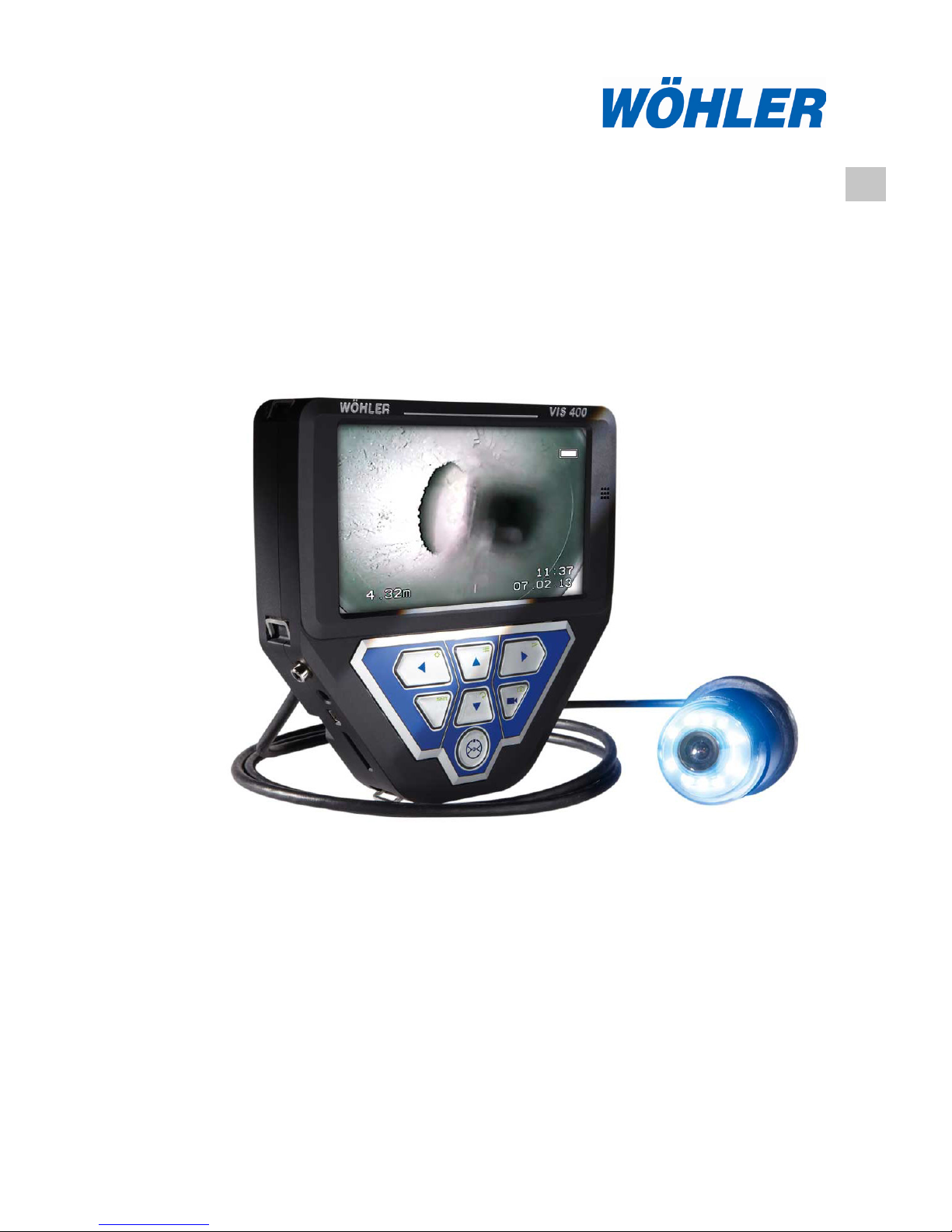
The measure of technology
EN
Operating manual
Colour monitor
Wöhler VIS 400
Best.- Nr. 23666 2018-02-14
Page 2

Contents
2
Contents
1 General Information .............................. 5
1.1 Operation Manual Information ....................... 5
1.2 Notes ............................................................. 5
1.3 Proper use ..................................................... 5
1.4 Basic features ............................................... 6
1.5 Transporting .................................................. 6
1.6 Information on disposal ................................. 6
1.7 Manufacturer ................................................. 6
2 Important information .......................... 7
3 Technical data ....................................... 9
5 Design and function ........................... 10
5.1 Monitor ........................................................ 10
5.3 Control panel ............................................... 12
6 Connections ........................................ 15
6.1 Connection options...................................... 15
6.1.1 Camera heads ............................................. 16
6.1.2 Camera cable .............................................. 17
6.1.3 Cable reel .................................................... 17
6.1.4 Camera viper ............................................... 17
6.2 Connecting the camera cable and camera
head ............................................................ 18
6.2.1 Connecting the camera cable ...................... 18
6.2.2 Connecting the camera head ...................... 19
7 Rechargeable battery status and
recharging ............................................ 20
8 Switching on the system and monitor ..
.............................................................. 21
9 Monitor settings .................................. 22
9.1 Monitor Menu .............................................. 22
9.2 Submenu „Picture“ ...................................... 22
9.2.1 Selecting the language ................................ 22
9.2.2 Setting the picture parameters in the monitor
menu ........................................................... 23
Page 3

Contents
3
9.3 Format ......................................................... 24
9.3.1 Turning the screen view ............................... 24
9.3.2 Changing the screen format ........................ 24
9.3.3 Selecting the video standard ....................... 24
9.4 Submenu „Option“ - Automatic shutdown .... 24
10 Settings via the menu ........................ 26
10.1.1 SETUP menu ............................................... 27
10.1.2 CALENDAR menu ....................................... 29
10.1.3 VIDEO menu................................................ 30
10.1.4 VIPER menu ................................................ 31
10.1.5 INFO menu .................................................. 31
11 Information displayed on the monitor ..
.............................................................. 32
11.1 Displaying the position of the camera head . 32
11.2 Time and date .............................................. 32
11.3 Memory Card Missing .................................. 32
12 Home function..................................... 33
13 Audio and video functions ................ 34
13.1 Recording .................................................... 34
13.2 Playback ...................................................... 34
13.3 Delete files ................................................... 35
14 Capture images ................................... 36
15 Delete files ........................................... 37
16 Transferring and showing images and
videos ................................................... 37
16.1 Transferring to the PC ................................. 37
16.2 Replaying videos on the PC ........................ 37
17 Guide accessories .............................. 38
18 Faults ................................................... 39
19 Maintenance ........................................ 40
19.1 Replacing the dome of the camera head ..... 40
19.2 Monitor ......................................................... 40
20 Warranty and service ......................... 40
Page 4

Contents
4
20.1
Warranty ...................................................... 40
20.2 Service ........................................................ 40
21 Accessories ......................................... 41
22 Declaration of conformity EG ............ 42
Points of sale and service ............................ 43
Page 5
0BGeneral Information
5
1 General Information
1.1 Operation Manual In-
formation
This operation manual allows you to safety work
with the Wohler VIS 400 Colour Monitor. Please
keep this manual for your information.
The Wohler VIS 400 should be used by trained
professionals for its intended use only.
Warranty is voided by any damages caused by
not following this manual.
1.2 Notes
WARNING!
Not following this warning can cause injury or
death.
ATTENTION!
Not following this note can cause permanent
damage to the monitor.
NOTE!
Usefull information
1.3 Proper use
The Wöhler VIS 400 color monitor is designed to
be used together with a suitable camera cable or
camera rod and camera head to visually inspect
and document the condition of pipes in shafts, for
example in flue gas systems, chimneys, ventilation systems as well as for inspecting underground drain pipes.
The device is designed to be used by trained professionals only. Any other use is considered improper use.
Page 6
0BGeneral Information
6
1.4 Basic features
Device
Scope of supply
Wöhler VIS 400 colour
monitor
Colour monitor
12 V rechargeable
battery
Power pack: 18 V, 1.5
A
SD memory card
4 GB
Protective case with
anti-glare visor and
carry strap
1.5 Transporting
To prevent damage to the Monitor use the original
carrying case when transporting.
The carrying case can be purchased separately.
1.6 Information on disposal
Electronic equipment does not belong in domestic
waste, but must be disposed in accordance with
the applicable statutory provisions.
You may hand in any defective batteries taken out
of the unit to our company as well as to recycling
places of public disposal systems or to selling
points of new batteries or storage batteries.
1.7 Manufacturer
Wöhler Technik GmbH
Wöhler-Platz 1
Bad Wünnenberg, Germany, 33181
Phone +49 2953 73-279
Fax +49 2953 7396-279
[email protected]
www.woehler.com
Page 7
Important information
7
2 Important information
Eye protection
WARNING!
Never point a connected camera head at
your own
or somebody else's eyes when the monitor is
switched on. The LEDs are extremely bright and
can cause eye damage.
WARNING!
When connected, guide the rod with due care and
attention. As the rod is made of flexible material, it
can make whipping movements if it slips. Protect
your eyes in particular.
Operating temperature
CAUTION!
Do not use the camera in temperatures above
40 °C. High temperatures can damage the cam-
era.
Resistance to water
CAUTION!
The colour monitor is not waterproof. Keep the
monitor dry and away from water!
Resistance to impacts
CAUTION!
The colour monitor is not impact resistant. Do not
throw or allow the case to fall!
Accessories
CAUTION!
Use only original Wöhler accessories and spare
parts!
Strong magnetic or electric
fields
NOTE!
Do not use the colour monitor near television towers, mobile radio equipment or other sources of
magnetic or electric fields, as these may impair
the
quality of the displayed image.
Page 8

Important information
8
Extraneous influences
NOTE!
Extraneous influences such as static discharges
can cause the device to malfunction. If a malfunction occurs, switch the monitor off and on again.
Page 9
Technical data
9
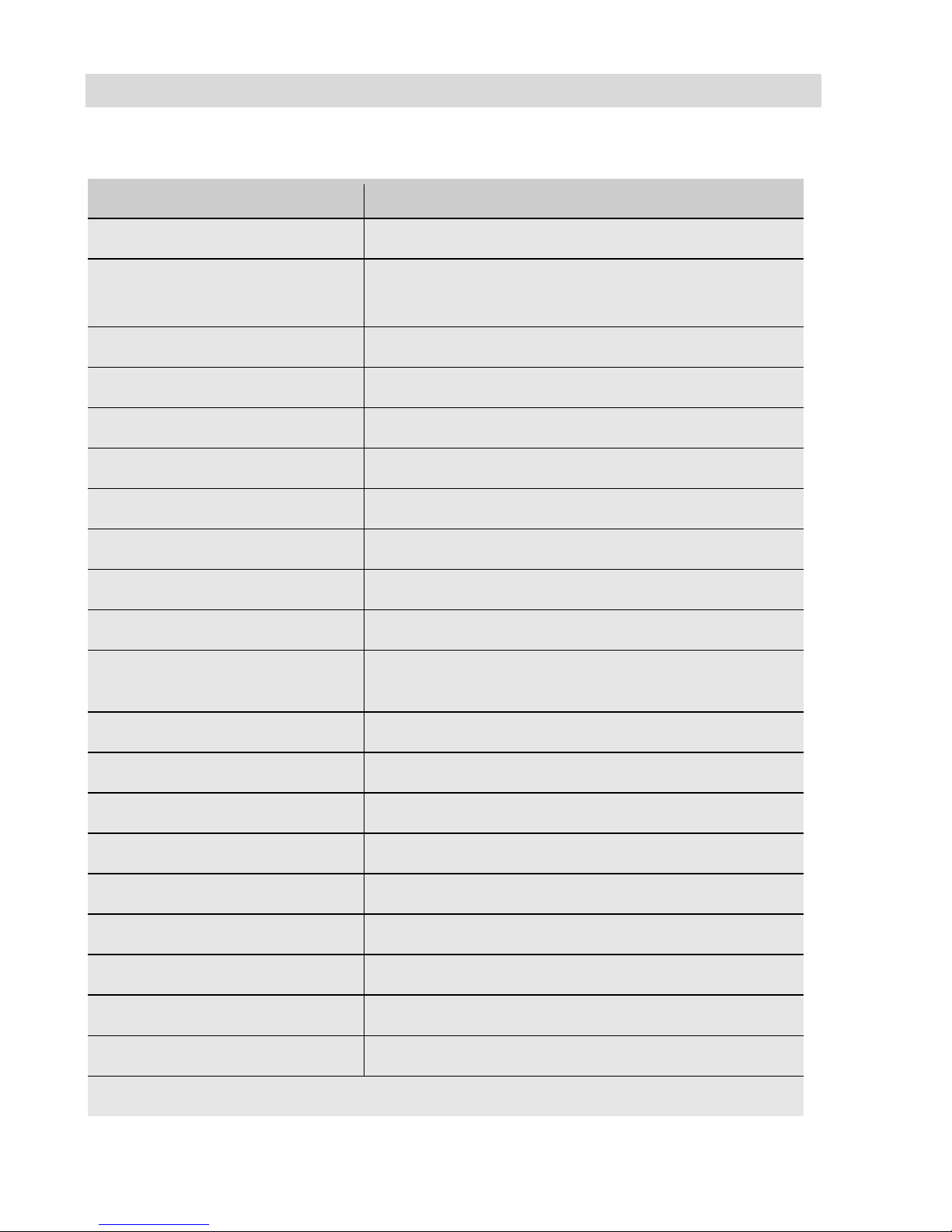
3 Technical data
Description
Details
TFT display
7"/ 16:9 format
Recording
Scope of delivery:
4 GB SD card (2.5 h recording capacity)
Optional memory cards
Max.
32 GB
Technology:
SD or SDHC
Velocity class:
2 - 10
Formatting:
For cards < 4 GB: FAT or FAT32, others: FAT 32
Interface
Mini USB port
Video output
FBAS signal
Power supply
12 V NiMH rechargeable battery, 2000 mAh
Battery operating time
Max. 2 h
(battery status is displayed)
Distance measurement:
Electronic meter counter
Operating temperature
0-40 °C
Storage temperature
-20 °C to 50 °C
Dimensions housing
Without case
199 x 196 x 40 mm
With case
210 x 210 x 60 mm
Weight
Without case
1200 g
With case
1700 g
Standard connection telescopic stand
Page 10
Design and function
10
4 Design and function
4.1 Monitor
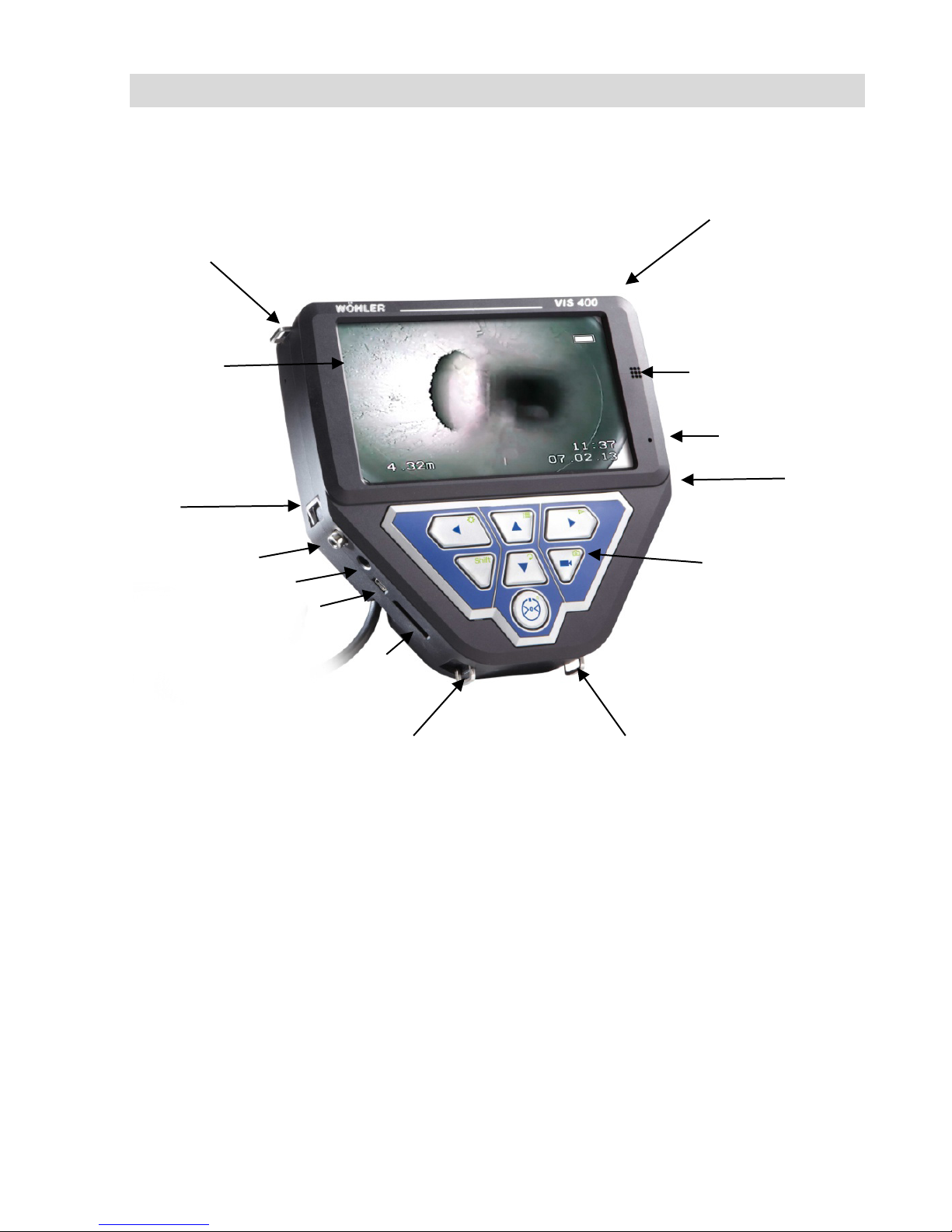
Fig. 1: Monitor and components
Legend
Front and side view:
1 Display
2 Loudspeaker
3 Control panel
4 Card slot for memory card
5 Mini USB port
6 Power pack connection
7 Video out
8 Eyelet to secure shoulder strap
9 Eyelet to secure wrist strap
10 Microphone
1 2 3 4 5
6 7 8 8 9
9
10
Page 11
Design and function
11
Fig.
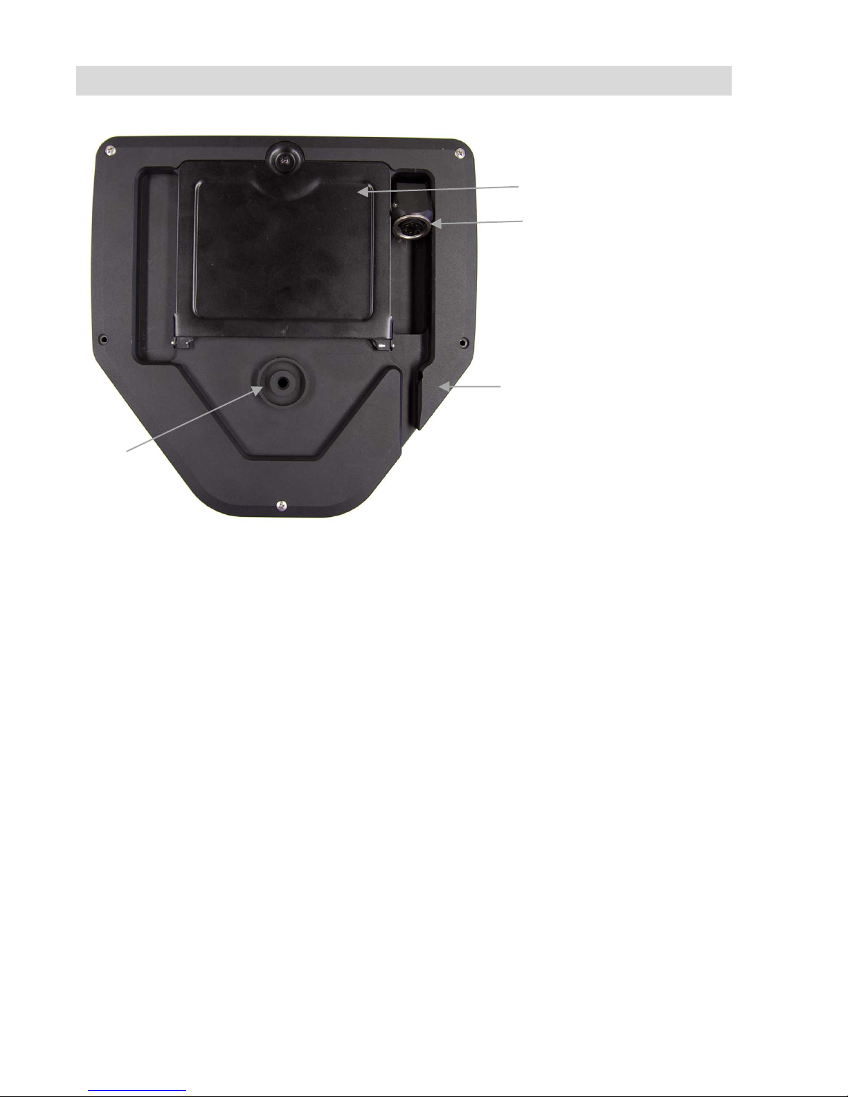
2: Monitor - rear view
Legend
Rear:
11 Battery compartment
12 Connection socket for camera cable or
rod
13 Cable guide
14 Standard telescopic stand connection
11
12
13
14
Page 12
Design and function
12
4.3 Control panel
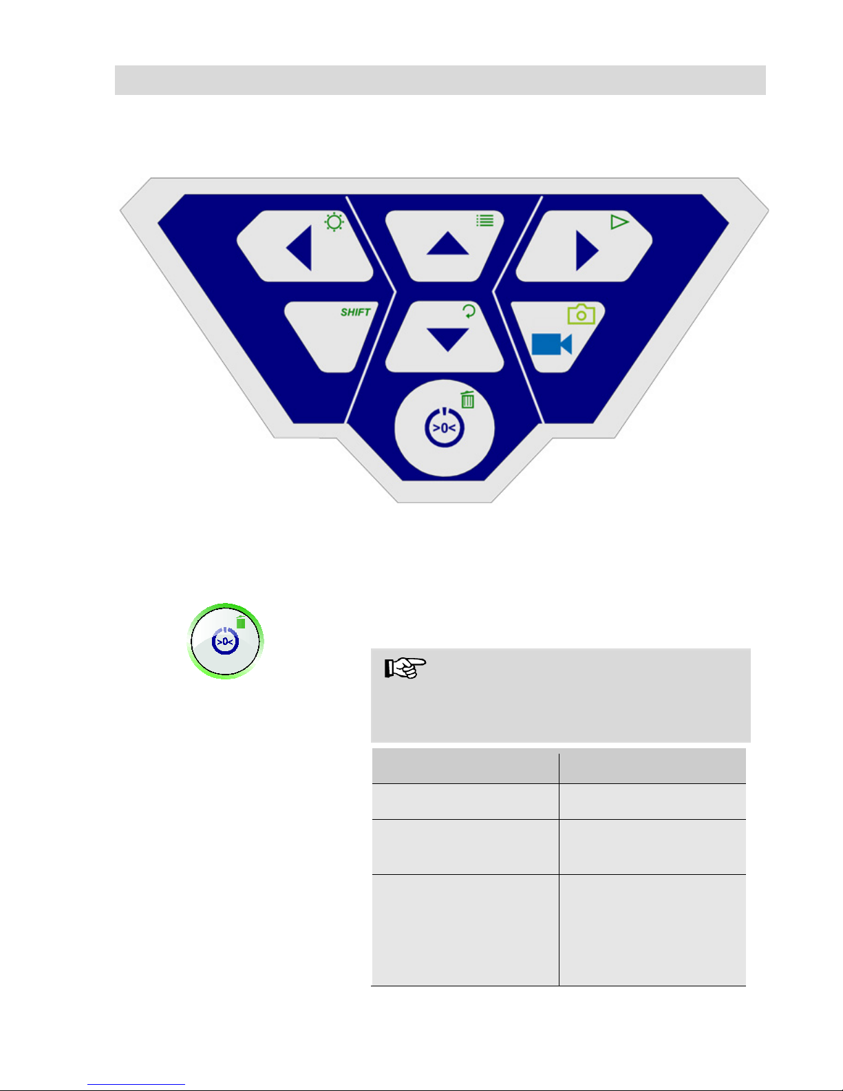
Fig. 3: Control panel
The keys on the control panel have the following functions:
ON/OFF key turns the whole camera system
on/off (monitor and connected camera head).
NOTE!
The ON/OFF key is framed by a green light
when the monitor is switched on and the battery
is charged.
Functions
The ON/OFF key
Press
Function
Hold 2 seconds
Switch system on/off
Briefly
Reset distance coun-
ter
When menu is acti-
vate (only when using
Ø 26 mm and
Ø 40 mm camera
heads)
Escape
Exit menu
Page 13
Design and function
13
Camera head operating keys
(this function is active only if the pan&tilt camera
head is connected, see accessories)
Tilt the camera head 180°
Camera head operating keys
(this function is active only if the pan&tilt camera
head is connected, see accessories).
Rotate the camera head 360°
VIDEO key
Start/stop recording video
SHIFT key
Activates the key functions depicted by green icons
on the top right corners of the keys.
NOTE!
When SHIFT MODE is activate, the SHIFT key
lights up and an S is displayed in the bottom middle of the screen.
Illumination key
Camera head Ø 26 mm, 40 mm:
Dimming function to set the brightness of the camera head lighting.
NOTE!
There are three levels of brightness available to
increase or dim the intensity of the camera head
lighting. The brightness is increased each time the
user presses the ILLUMINATION key three times
in sequence. The fourth time the user presses the
key, the lighting returns to the lowest level of
brightness.
Camera head Ø 51 mm:
Switch LEDs on and off.
+
Page 14
Design and function
14
If the Additional Illumination, type plug-in, is in-
stalled (article 4194), the LEDs of the camera head
and the pluggable illumination (article 4194) will be
switched on and off at the same time.
MENU key:
Make settings
PLAY key
Playback recorded videos
HOME key
(this function is active only if the Ø 40 mm, pan&tilt
camera head is connected, see accessories).
Aligns the camera head to a straight position –
displays view parallel to the ground above
IMAGE key
Capture image / snapshot
NOTE!
Images are saved in .jpg format; it is possible to
display the images on a PC from the SD card. I
DELETE key
Delete an image or video selected in PLAY mode.
+
+
+
+
+
Page 15
Connections
15
5 Connections
5.1 Connection options
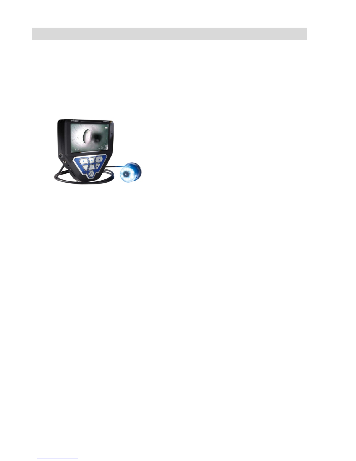
The Wöhler VIS 400 monitor is a component of an expandable modular inspection system that the user can configure to meet the demands of any working environment. The
various connection options are described below; please also refer to the Section Accessories.
Fig. 4: Ready to go – monitor complete
with connected camera cable and cam-
era head
To perform inspections, a Wöhler camera rod and a
camera head or a Wöhler camera cable and a
camera head must be connected to the monitor.
Page 16
Connections
16
5.1.1 Camera heads
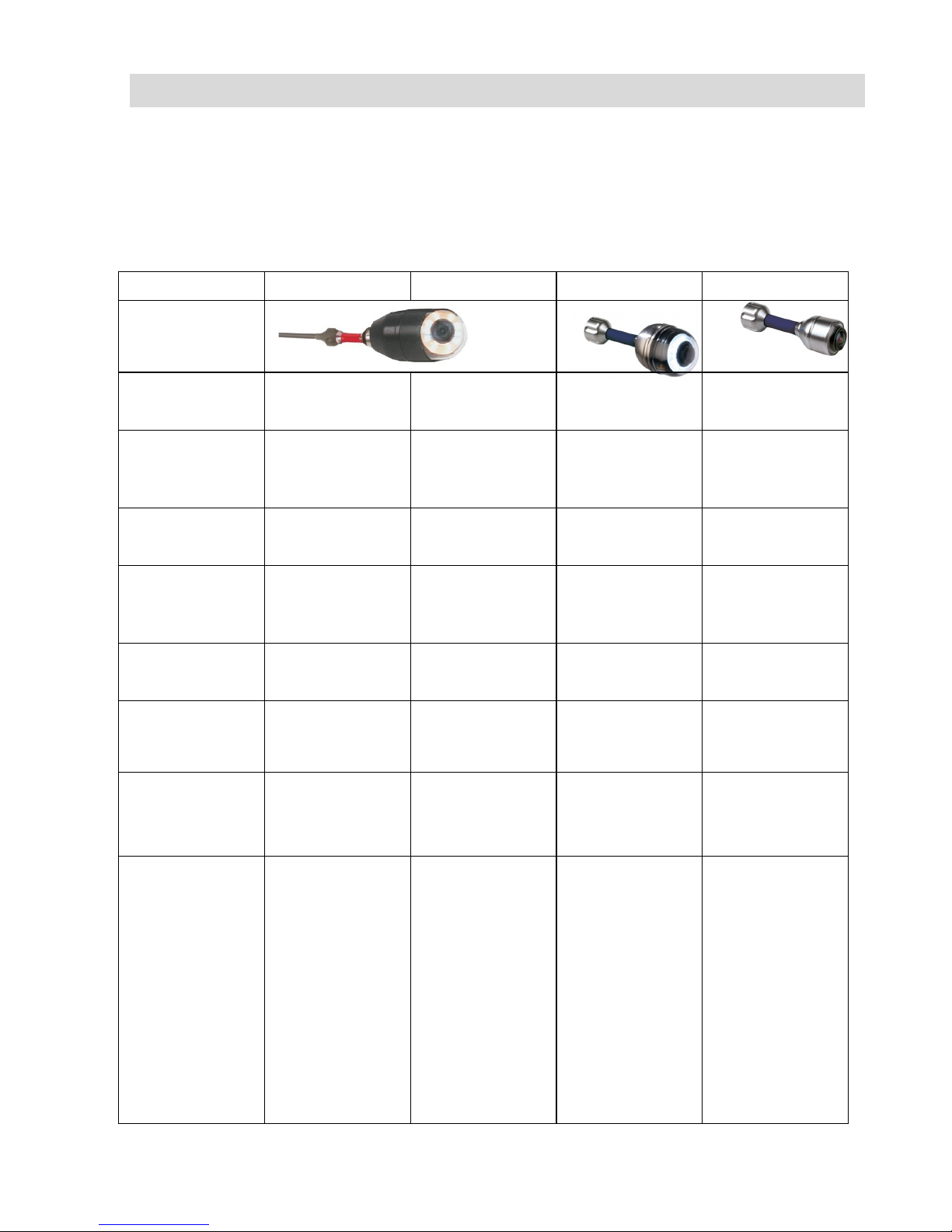
The camera head selected affects the display options on the monitor. It is possible to
connect the following camera heads:
Diameter
Ø 51 mm
Ø 51 mm
Ø 40 mm
Ø 26 mm
Image
Colour
Light sensitivi-
ty
O.08 Lux
0.4 Lux
0.5 Lux
0.5 Lux
Pan&Tilt
Position indi-
cator
Home function
Integrated
locator transmitter
Resistance to
water
waterproof
IP 67
(30 min / 1 m)
waterproof
nach IP 67
(30 min / 1 m)
waterproof
nach IP 67
(30 min / 1 m)
waterproof
nach IP 68
(30 min/ 30 m)
Application
Chimney in-
spections
Chimney in-
spections
Waste water
lines Ø 70 mm
and larger
House con-
nections up to
Ø 200 mm
Flue gas lines
60 mm and
larger
Waste water
lines Ø 40 mm
and larger
Ventilation
pipes 40 mm
and larger
Flue gas lines
up to approx.
125 mm
Page 17
Connections
17
5.1.2 Camera cable
Fig.
5: Inspections using camera cable
from above
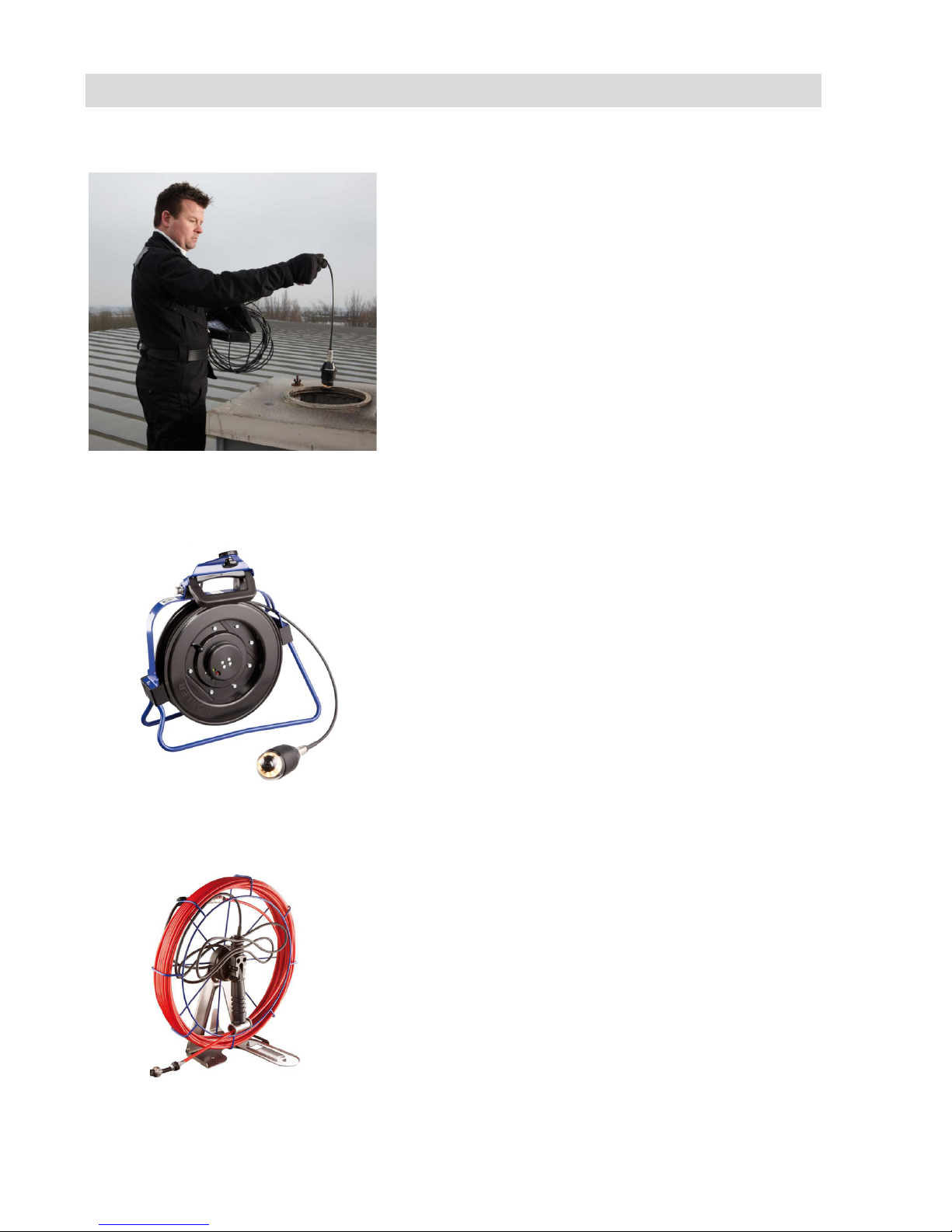
The most effective method of inspecting things
such as chimney and downpipes is from above, for
example when standing on the roof. To do so, it is
necessary to connect a camera cable to t
he moni-
tor.
5.1.3 Cable reel
Fig. 6: Wöhler cable reel with camera
head connected
The Wöhler cable reel can store up to 30 m of
camera cable and proves extremely useful when
working with the cable. The monitor is secured to
the cable
reel using the connection for the telescop-
ic stand.
5.1.4 Camera viper
Fig. 7: Wöhler camera viper
If it is not possible to perform an inspection from
above, it will be necessary to connect a camera
viper
. It is far easier to handle
the camera rod when
used in conjunction with a Wöhler camera viper,
which can store up to 30 m of camera rod.
Page 18
Connections
18
5.2 Connecting the camera cable and camera head
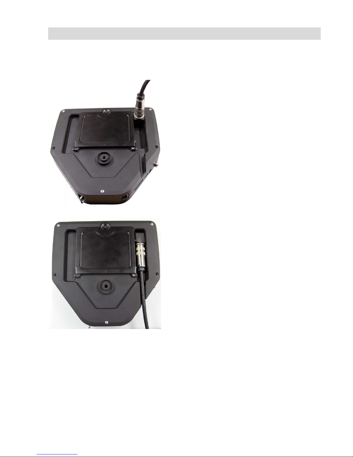
5.2.1 Connecting the camera cable
Fig. 8: Camera cable connection
• Flip up the eight-pole female connector locat-
ed on the rear of the monitor (Fig 2, part 12).
•
Insert the male connector of the camera cable
or rod into the female connector, then turn the
locking ring clockwise to secure the connection.
Fig. 9: Camera cable fed through guide
• Move the female connector with connected
cable or rod to a suitable working position:
•
Feed the cable through the guide, if you wish
to put down the monitor.
Page 19
Connections
19
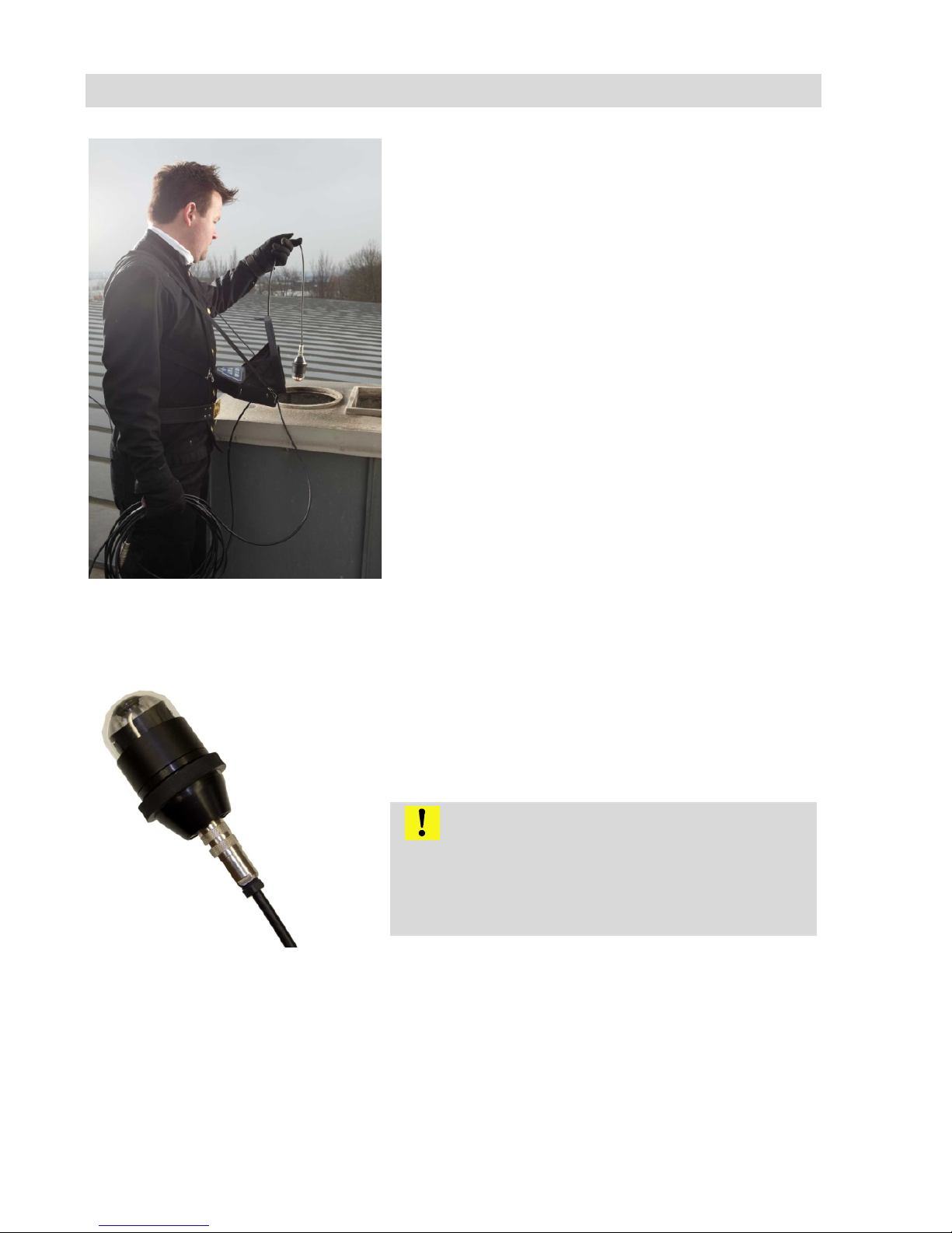
Fig. 10: Carrying the camera in the cam-
era case
• Allow the cable to hang down when you carry
the monitor with the shoulder strap over your
shoulder.
5.2.2 Connecting the camera head
Fig.
11: Wöhler Ø 51 mm camera head
connected to a camera cable
Insert the male cable connector (or male camera
rod connector) at the other end into the eight-pole
female connector of the camera head, then turn
the locking ring clockwise to secure the connection.
CAUTION!
The connection is only waterproof when the connectors are joined together properly.
Tighten the locking ring using your fingers; never
use pliers!
Page 20
Rechargeable battery status and recharging
20
6 Rechargeable battery status and recharging
WARNING!
Risk of injury when handling the rechargeable
batteries improperly!
Never open the rechargeable battery housing.
Do not throw rechargeable batteries into a fire or
expose to high temperatures. There is a risk of
explosion!
If handled improperly, a liquid may emerge from
rechargeable batteries that can cause skin irritation. Avoid contact with the liquid. Rinse skin with
large amounts of water if it comes into contact
with the liquid. If the liquid comes into contact with
eyes, rinse with water immediately for 10 minutes
and consult a doctor immediately!
WARNING!
Danger of death by electrocution!
Never touch an electrical outlet with wet hands!
Do not expose the power pack to moisture!
Never pull the cable to remove the power pack
from the electrical outlet - it could rip out the cable!
Operate the power pack only when the mains
power supply is the same as the voltage stated on
the rating plate!
CAUTION!
Switch off the camera system before charging the
battery.
CAUTION!
If the camera is not used regularly, we recom-
mend to discharge the battery by powering on the
camera. After that charge the battery completely.
Repeat this procedure after approx. 6 weeks.
Page 21
Switching on the system and monitor
21
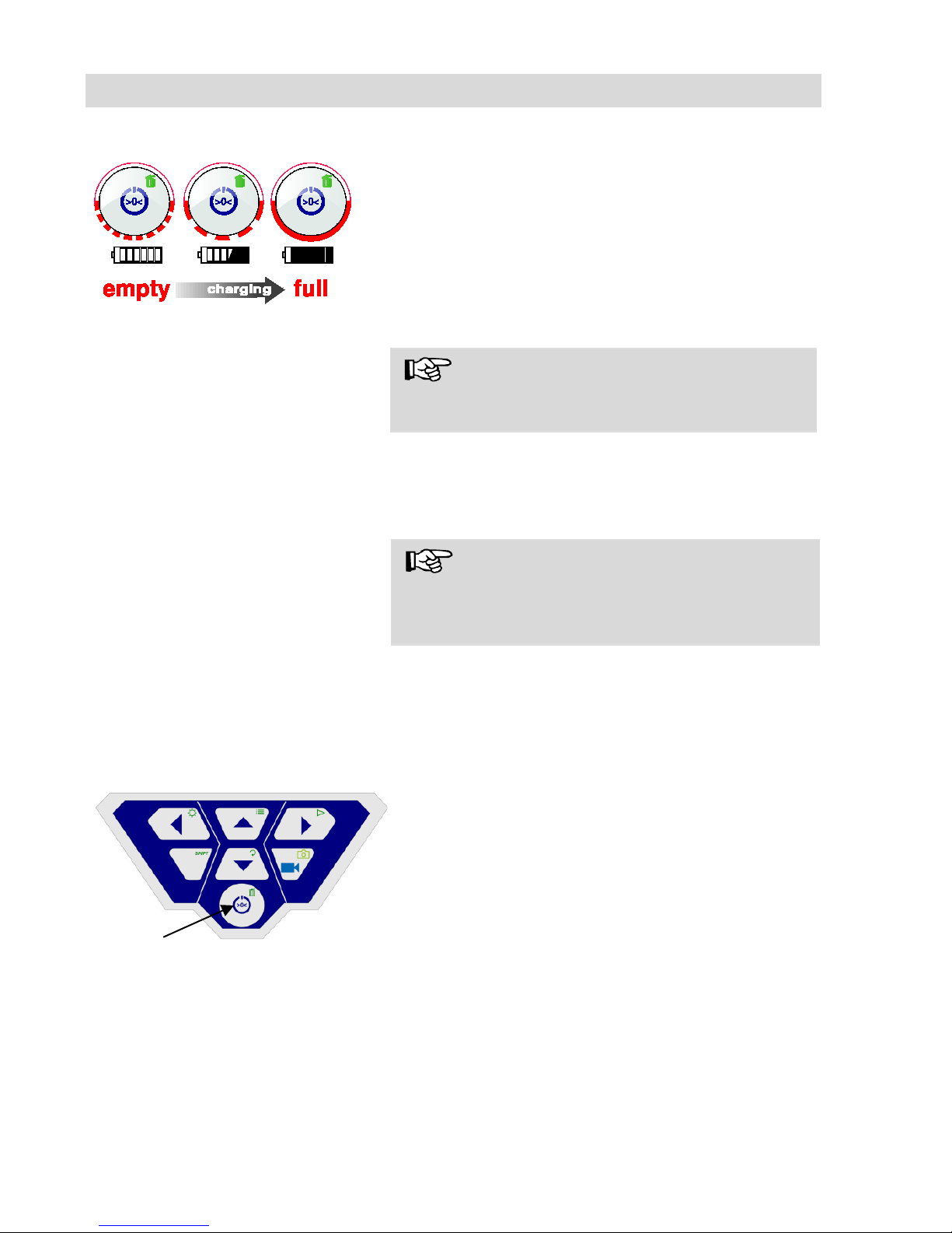
Charging rechargeable batteries
Fig.
12: Schematic overview of battery
recharging
To recharge the battery, proceed as follows:
•
Connect the power pack to the charger con-
nection of the device and the main power
supply.
The lower half of the light framing the ON/OFF
key flashes red during the recharging process;
when the battery is fully recharged it lights up red
continuously as long as the power pack remains
connected.
NOTE!
The operating time of the rechargeable battery is
approx. 120 minutes.
7 Switching on the system and monitor
• Insert a memory card (max. 32 GB).
NOTE!
If you are using a memory card other than the one
included in the scope of supply, you must format
it
first (FAT32) before you can use it on a PC.
To format the card, proceed as follows:
•
Insert the card into the card slot of your PC.
•
In the Explorer, right-click the removable me-
dia memory card, then select "Format".
•
Select FAT32 (default) and 32 kilobytes.
Fig.
13: ON/OFF key
• To switch on the device, briefly press the
ON/OFF key at the bottom of the control panel.
•
When the device is switched on, the light fram-
ing the ON/OFF key lights up green. The video
image is displayed on the monitor after about
5 seconds.
Page 22
Monitor settings
22
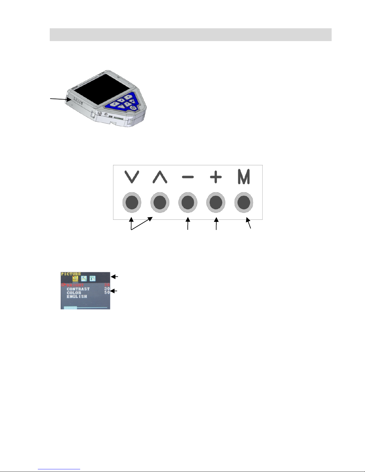
8 Monitor settings
Fig. 14: openings for adjusting
the monitor settings
On the left hand of the monitor there are 5 open-
ings. With a pointed object press into these openings to adjust the monitor settings.
8.1 Monitor Menu
• Press M, to enter the monitor menu.
In the upper line, different icons will show 3 differ-
ent submenus: Picture, Format, Option, Off
• Press M, to change between the submenus.
• Press „˄“ or „˅“, to switch between the param-
eters.
• Press „–“, to reduce a value.
• Press „+“, to increase a value.
8.2 Submenu „Picture“
8.2.1 Selecting the language
Nine different languages can be selected for the
monitor menu: english, german, frensh, spanisch,
portuguese, italien, dutch, russian and Chinese.
• Press M to select the first icon (Picture).
• Press ˅ until you have reached the last pa-
rameter.
submenus
parameters
Select pa-
rameters
reduce
value
increase
value
Activate monitor menu/
select submenu
Fig. 15: Picture menu
Page 23
Monitor settings
23
• Press + to select the language
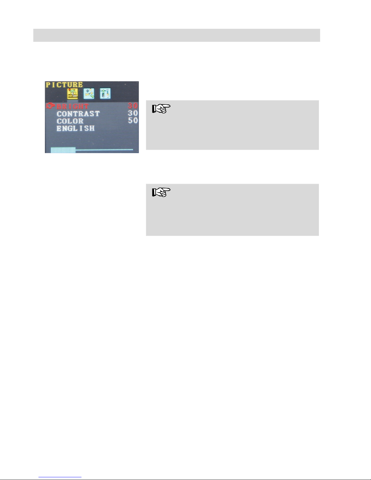
8.2.2 Setting the picture parameters in the monitor menu
Fig. 16: Default settings
In the picture menu, the brightness, the contrast
and the color can be adjusted from 0 to 100
Note!
The default settings are:
Bright: 30
Contrast: 30
Color: 50
A bar below the parameters shows the adjustment
level.
Note!
When the camera head Ø26 mm or Ø 40 mm is
connected, the video quality can also be adjusted
in the camera menu, see chapter 10.
Page 24
Monitor settings
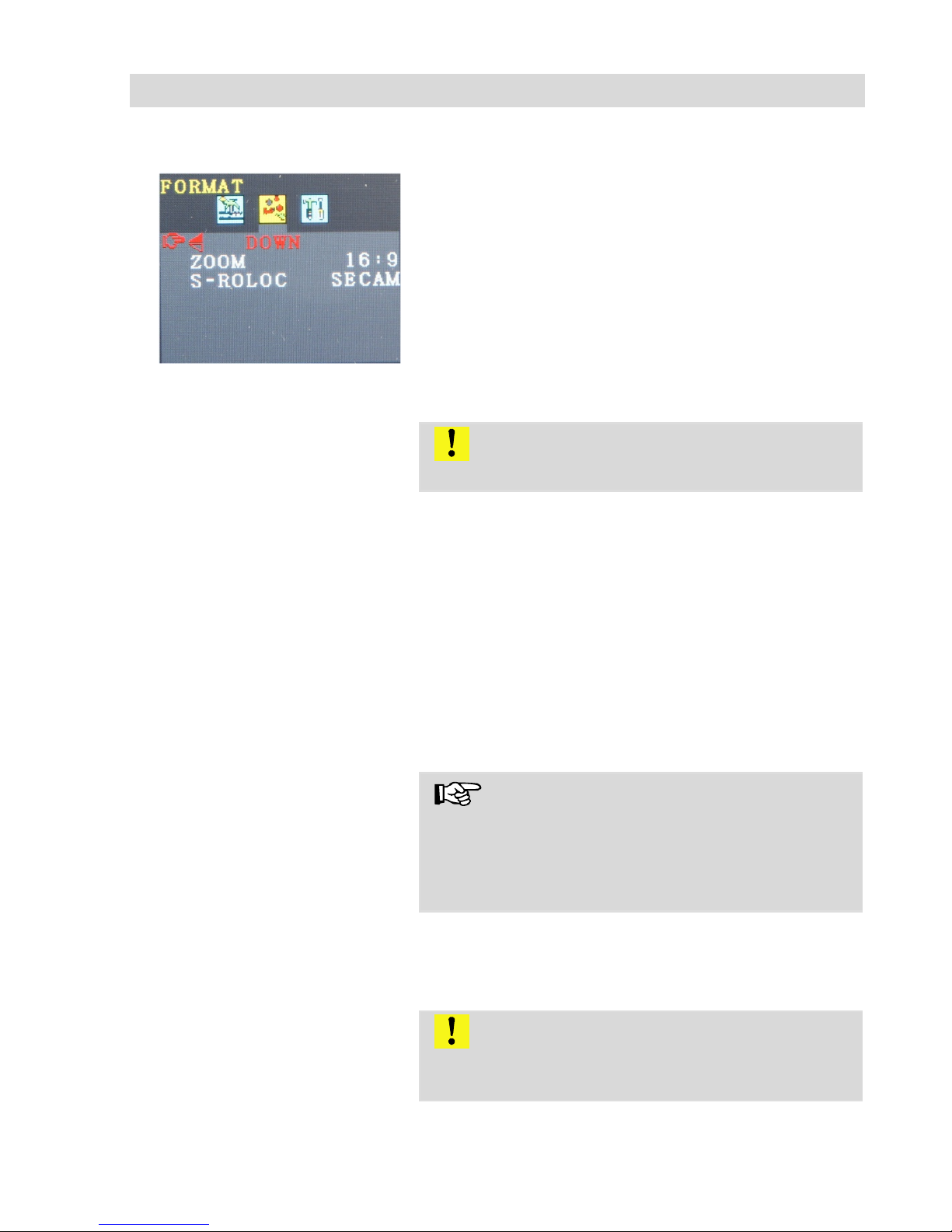
24
8.3 Format
Fig. 1: Submenu Format
In the Format Menu the user can turn round the
screen, the screen format can be changed from
16:9 to 4:3 and the video format can be selected.
• Press M to select the second icon (Format).
8.3.1 Turning the
screen view
CAUTION!
We recommend not to turn the screen view.
• Press ˅ to select the first parameter (down).
• „Down“ shows the normal view.
If absolutely necessary, turn the screen by pressing
the + or –: normal (turns 180°), down reflected and
normal reflected.
8.3.2 Changing the
screen format
• In the format menu press ˅ to select the zoom
parameter.
• Press + or - to change between 16:9 and 4:3
or FIT.
HINWEIS!
If you select 16:9 or 4:3 there will be frames on the
screen. If you choose FIT the video will perfectly fit
to the screen.
8.3.3 Selecting the
video standard
In the submenu „ S-Roloc the video standards PAL
> NTSC > SECAM > AUTO can be selected. This
setting only affects the screen. The default setting
is “Auto”.
CAUTION!
We urgently recommend not to change the default
setting „AUTO“.
8.4 Submenu
In the submenu „Option“ the user hast he possibility
to activate an auto off-function for the monitor
Page 25
Monitor settings
25
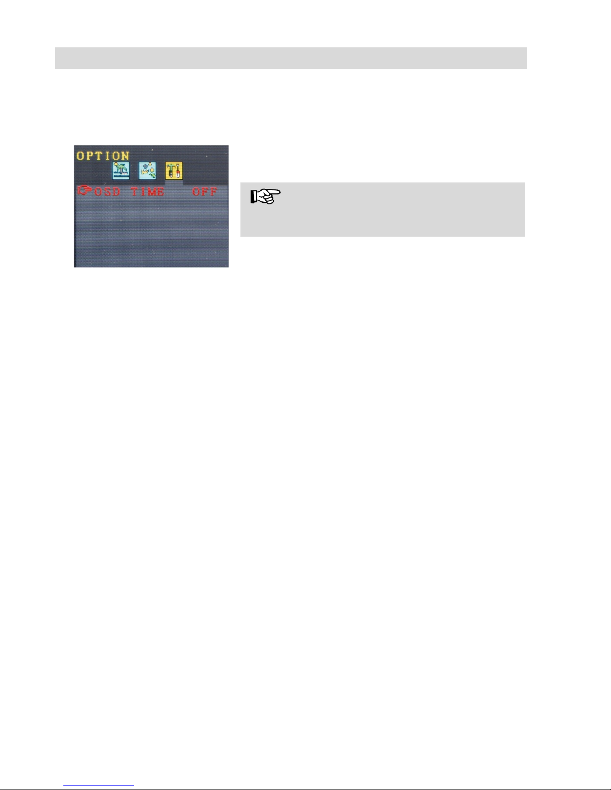
„Option“ -
Automatic
shutdown
Fig. 17: automatic shutdown
deactivated
menu:
• Press M to select the third icon (Option).
• Press + or – to select the time after which the
monitor menu shall turn off automatically: 5 s >
10 s > off.
Note!
“OFF” is the default setting, so that the automatic
shutdown will be desactivated.
Page 26
Settings via the menu
26
9 Settings via the menu
• After switching on the device, press the SHIFT
key
The green light framing the SHIFT key lights up
and an S is displayed in the middle at the bottom
of the monitor. This indicates that SHIFT mode is
active and the second functions marked in green
on the keys are enabled.
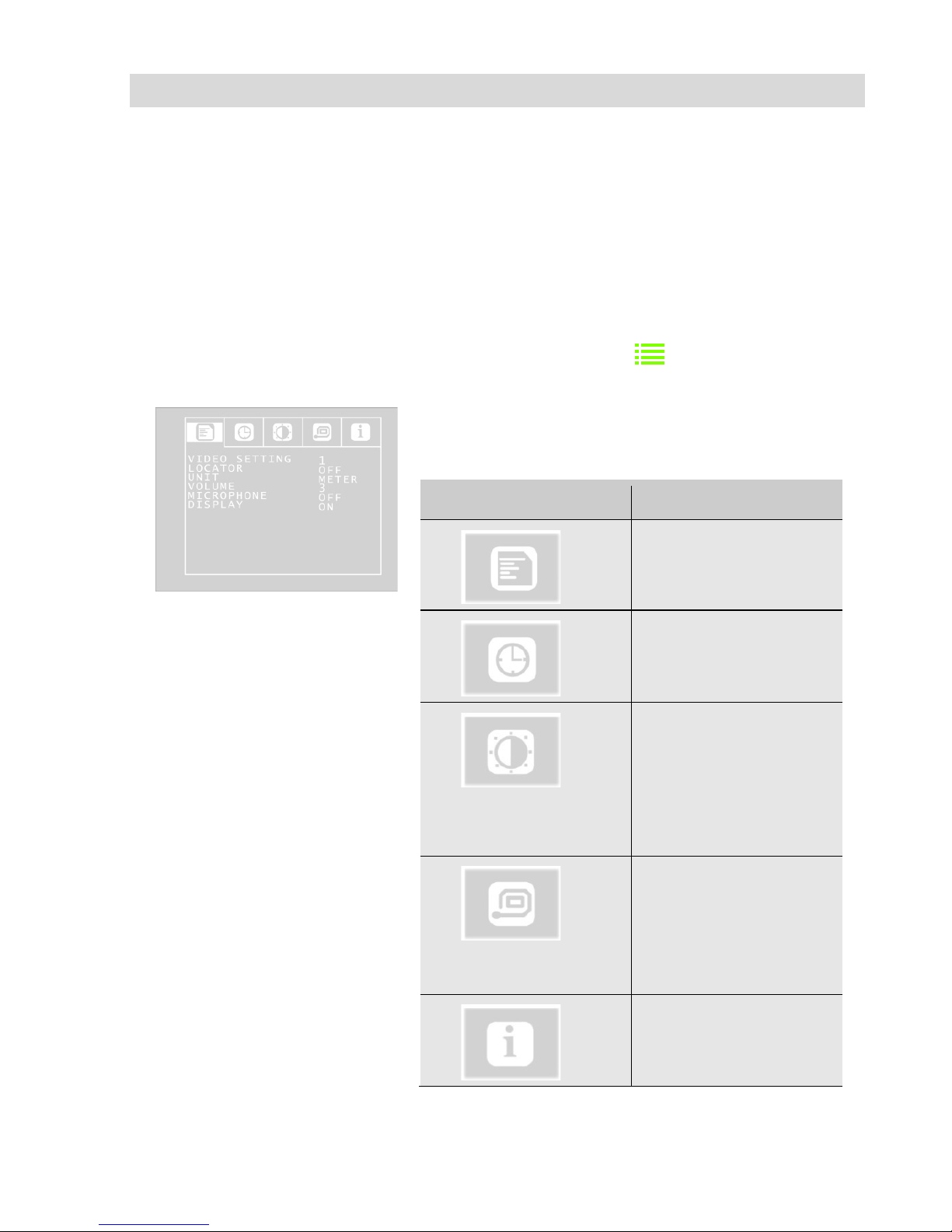
• Press the Menu key
Fig. 18: SETUP menu
The menu opposite is displayed on the screen with
5 sub-menus.
.
Icon
Menu
SETUP menu
CALENDAR menu
VIDEO menu
(If you work with the
camera head Ø 51
mm, there will be no
video menu)
VIPER menu
(only active, when the
cable reel is connected)
INFO menu
Page 27
Settings via the menu
27
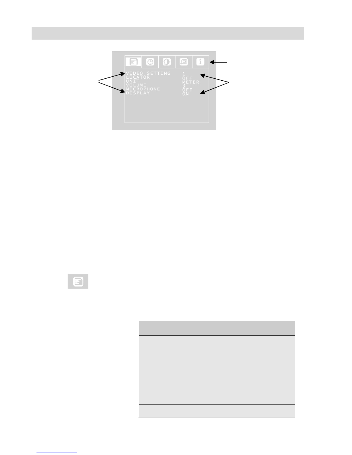
Fig. 19: SETUP menu
Navigating to the sumenu
• Using the up/down arrows, navigate to the
submenu line. Using the left/right arrow keys
navigate to the submenu.
Navigating to the parameters
• Using the up/down arrows, navigate to the
corresponding parameter. Select the desired
setting using the left/right arrow keys.
• Press the ON/OFF key to confirm your selec-
tion and exit the menu.
• If there is no disc icon to save the settings,
your settings will be saved automatically when
you exit the menu.
The user can select the following parameter settings:
9.1.1 SETUP menu
Video Setting 1 – 3
(only if using the camera
head Ø 40 mm and 26 mm)
The user can switch between 3 pre-defined video
settings. The video settings 1 and 2 cannot be
altered.
Video
Recommended
Video Setting 1
Recommended for
pipes, good long field
of vision
Video Setting 2
Recommended for
chimneys; dark areas
are made to appear
brighter
Video Setting 3
User-definable set-
submenu line
settings
submenus
Page 28
Settings via the menu
28
tings
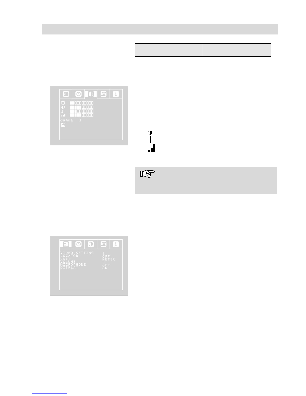
To define Video Setting 3, proceed as follows:
Fig. 20: User-definable Video
setting 3
• In the menu view, use the up arrow key to
navigate to the submenu line and then use the
right arrow key to select the VIDEO tab. Adjust
the settings as described in section
10.1.3
• Adjust the following settings as required:
☼ Brightness
: Contrast
: Contour sharpness
Colour saturation
Gamma: Gamma curve setting (0-3)
NOTE!
Adjustments to the gamma curve affects brightness curve settings.
• To save your settings, use the down arrow key
to select the disc symbol below the parameter.
Press the right or left arrow key.
This saves the settings for Video 3. For some seconds a hook will appear insteas of the disc icon.
Fig. 21: SETUP Menu
• Return to the SETUP menu view using the
arrow keys.
LOCATOR OFF/ON
(only with camera heads Ø
26 and 40 mm)
This command allows the user to switch the
transmitter integrated in the camera head on and
off. The Wöhler L 200 Locator is able to locate the
camera head with the aid of signals transmitted by
the transmitter.
(only Ø 40 mm and Ø 26 mm camera heads are
equipped with an integrated transmitter).
Page 29
Settings via the menu
29
ON: Transmitter is switched on
OFF: Transmitter is switched off
NOTE!
The camera consumes less power when the
transmitter is switched off. However, it is not pos-
sible to locate the camera head when the transmit-
ter is switched off.
UNIT METER/FEET
Set the distance displayed on the screen to meters
or feet, when the cable reel or the viper is connected.
VOLUME 0 - 3
This command allows the user to adjust the vol-
ume when recorded audio is played back.
MICROPHONE ON/OFF
This command allows the user to switch the mi-
crophone ON or OFF. When the microphone is
switched on, the user is able to add an audio annotation, which will be played back together with
the recorded video.
The default setting is "OFF"; this means no sound
is recorded when recording a video.
DISPLAY ON/OFF
This command allows the user to switch the on-
screen display On or Off. Select "ON" if you wish
to display the battery status indicator and the date
on-screen.
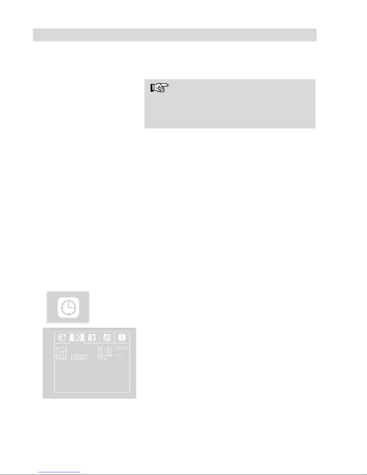
9.1.2 CALENDAR menu
Fig. 22: Settings in the SETUP
menu
Use the arrow keys to navigate to the CALENDAR
menu. The following settings are available here:
DATE
Set the date.
Page 30
Settings via the menu
30
NOTE
The date will be recorded together with the video.
TIME
Set the time. The time will be recorded together
with the video.
DATE FORMAT
Set the date format to either Day.Month.Year or
Month/Day/Year
TIME FORMAT 12h/24h
Set the time format to either 12 hour format or 24
hour format.
Exit menu
To exit the menu, press the ON/OFF key.
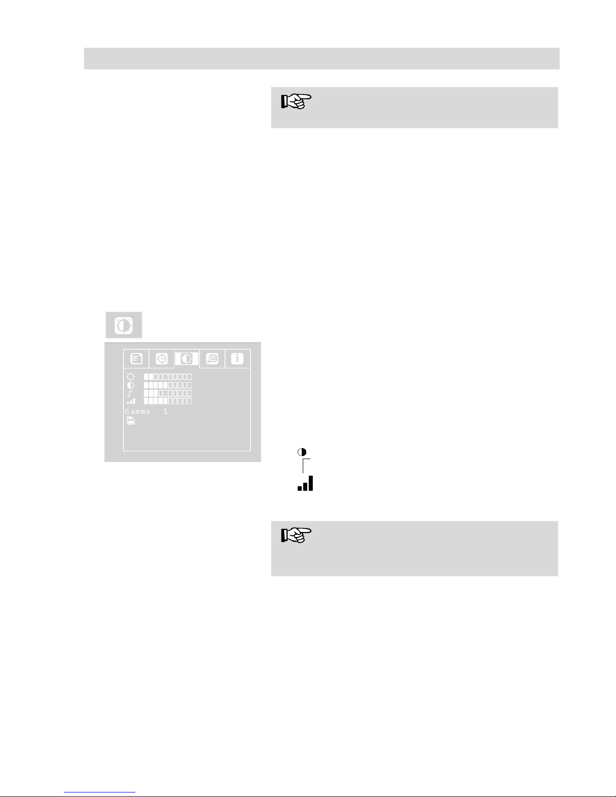
9.1.3 VIDEO menu
The VIDEO menu will only be active, if the camera
heads Ø 40 mm and 26 mm are used.
Fig. 23:VIDEO menu
In the video menu the user can define the video
settings. These settings will be stored as video
settings 3. If the user changes anything in the video menu, automatically video settings 3 will be
active (see SETUP menu)
• Adjust the following settings as required:
☼ Brightness
: Contrast
: Contour sharpness
Colour saturation
Gamma: Gamma curve setting (0-3)
NOTE!
Adjustments to the gamma curve affects brightness curve settings.
• To save your settings, use the down arrow key
to select the disc symbol below the parameter.
Press the right or left arrow key.
• This saves the VIDEO SETTINGS 3. After that
a hook will appear for some seconds instead of
the disc icon.
Page 31
Settings via the menu
31
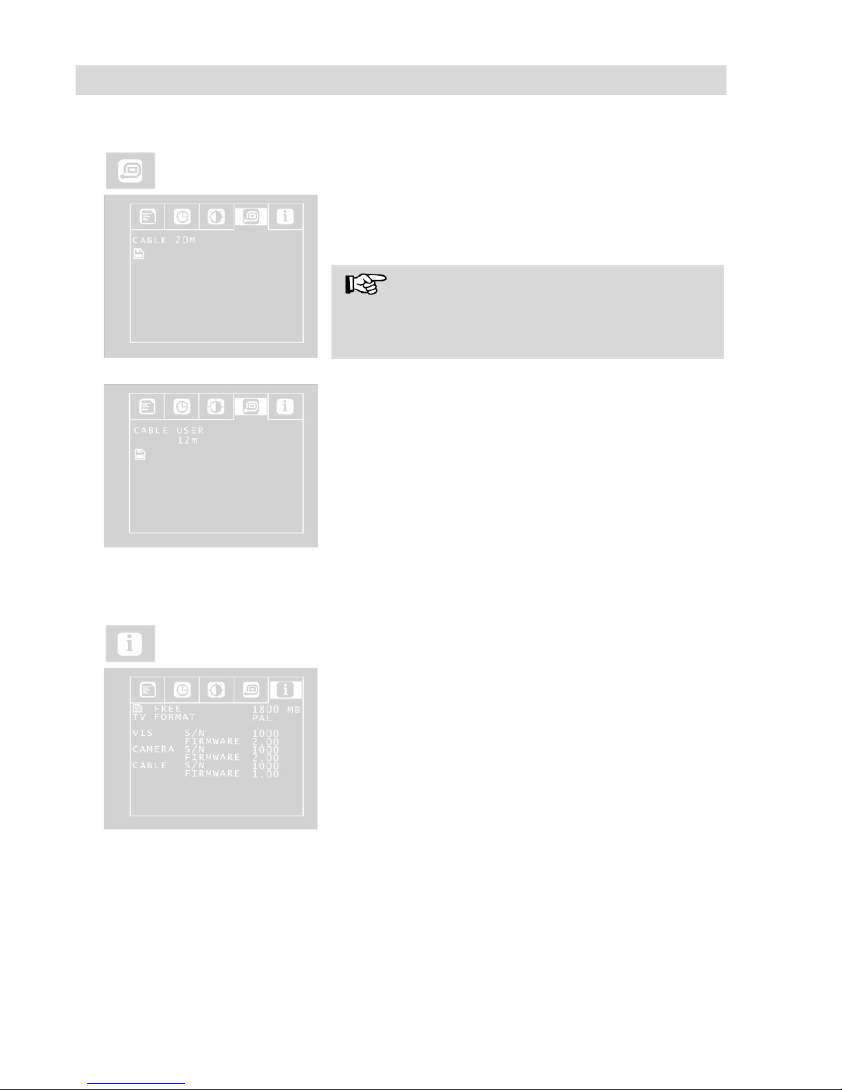
9.1.4 VIPER menu
The VIPER menu is only active, when a cable reel
is connected to the camera.
Fig. 24: VIPER menu
• With the arrow keys go to CABLE and select
20 m or 30 m according to the cable length
• Click on the disc icon to save the setting.
HINWEIS!
If the viper or the cable reel is connected to the
camera, the drop length of the cable will be displayed in the lower left part of the screen.
Fig. 25: User definable settings
in the VIPER menu
There is also the possibility to select “USER” in-
stead of 20 m or 30 m.
• Select USER if you work with another cable
length.
• Enter the length of your cable with the arrow
keys.
It is possible to enter a length between 0 and 30
m.
• Click on the disc icon to save the setting.
9.1.5 INFO menu
Fig. 26: INFO menu
The INFO menu shows important information
about your camera system. It is not possible to
make any settings in this menu.
FREE: Information about the free storage space
on the memory card.
TV FORMAT: TV format of the camera head (PAL
or NTSC)
VIS S/N: Serial number of the camera system
VIS FIRMWARE: Firmware version of the camera
system
CABLE S/N: Serial number of the camera head
CAMERA FIRMWARE: Firmware version of the
camera head
CABEL S/N: Serial number of the cable reel or
viper (if connected)
CABEL FIRMWARE: Firmware version of the ca-
Page 32
Information displayed on the monitor
32
ble reel or viper (if connected)
10 Information displayed on the monitor
10.1 Displaying the position of the camera head
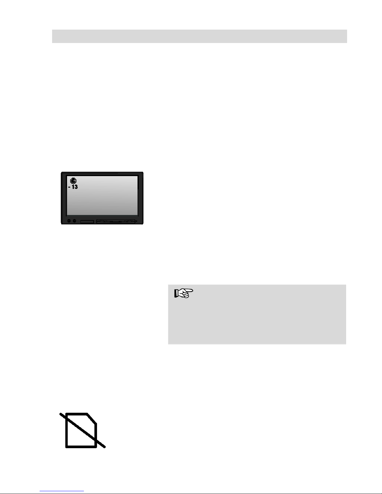
The position can only be displayed if a Ø 26 mm or Ø 40 mm Wöhler camera head
is connected.
Pointer symbol
Fig. 27: Display with pointer sym-
bol and number of degrees
A pointer symbol displayed in the top left corner
of the screen always indicates the direction of
gravity, meaning, towards the bottom. This ensures the user is able to recognize where top and
bottom are in the pipe.
A circle is displayed around the symbol if the camera head faces vertically upwards.
A cross is displayed in the middle of the symbol if
the camera head faces vertically downwards.
Number of degrees
The number of degrees displayed underneath
indicates the downward gradient of the pipe.
Example graphic: - 13° corresponds to a down-
ward grade of 13°.
NOTE!
Example:
Camera head facing vertically upwards: + 90°
Camera head facing vertically downwards: -90°
Camera head is aligned parallel to the ground
above: 0°
10.2 Time and date
The time and date are displayed in the bottom
right corner. The recorded time is displayed when
the video is played back..
10.3 Memory Card
Missing
If no memory card is plugged into the card slot, a
crossed out memory card icon will appear on
screen. The icon will disappear, as soon as the
memory card will be inserted.
Page 33
Home function
33
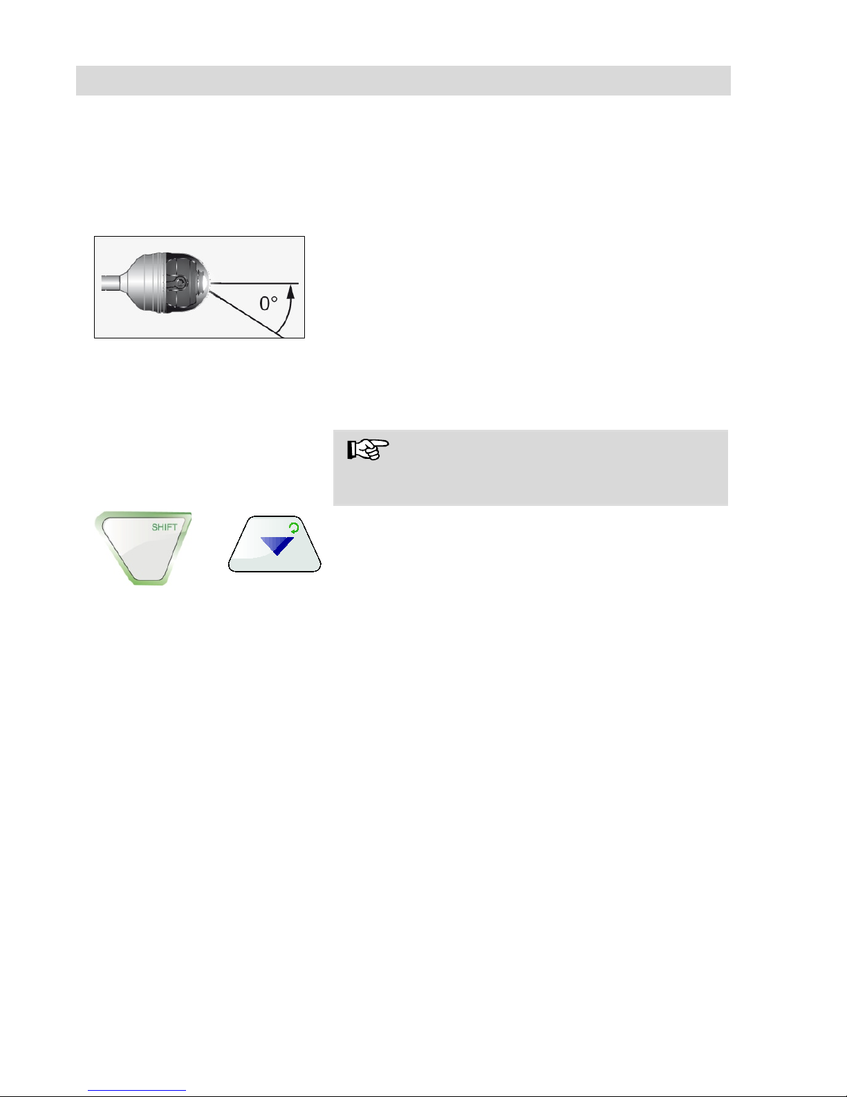
11 Home function
It is only possible to activate the home function when the Ø 40 mm Wöhler camera
head is connected.
The home function ensures the camera head is
automatically aligned to a straight position, ensuring the camera "looks straight ahead".
Moreover, when the user presses the HOME key,
the camera head aligns itself so that the display is
parallel with the ground above (this function is
deactivated if the camera head faces 90° upwards
or downwards. Under these circumstances, the
optics can only be guided forwards).
NOTE!
To determine the grade described under section
11.1, the camera head must be aligned straight.
• To activate the home function, press the
SHIFT key and then the HOME key.
+
Fig. 28. Home function
Page 34
Audio and video functions
34
12 Audio and video functions
12.1 Recording
Record video
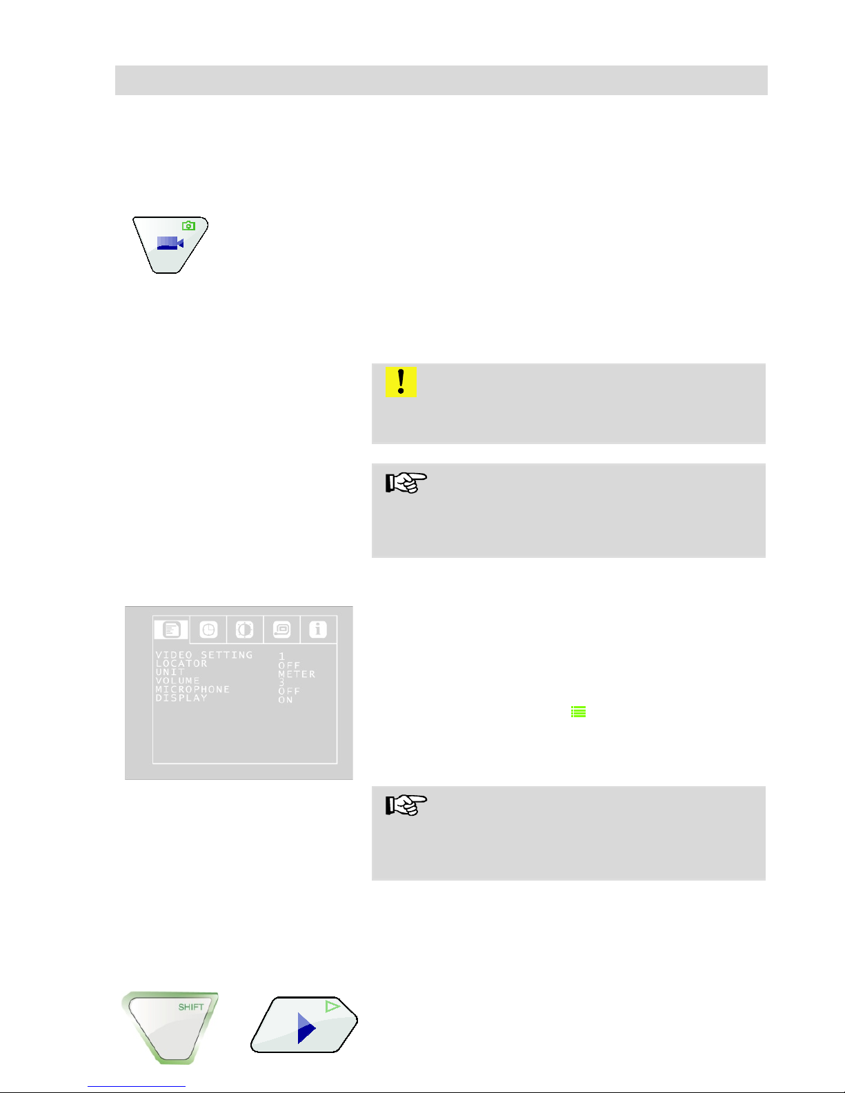
• To begin recording a video, press the Record
video key.
The RECORD VIDEO key is framed by a red
flashing light when recording is in process, and a
red dot is displayed on the screen.
• To stop recording, press the Record video key
again. The video is stored in ASF format on
the memory card.
CAUTION!
Ensure the power supply is not interrupted when
recording a video.
NOTE!
The camera will automatically stop recording a
video after 30 minutes and then start a new record
again.
Recording an audio annotati-
on
Fig. 29. SETUP menu
The user is able to add an audio annotation when
recording a video; this is recorded together with
the video and jointly saved as an ASF file to be
played back together with the video. The microphone must be switched on to be able to record an
annotation.
• Press the SHIFT key and then the Menu key to
access the Menu tab.
• Use the arrow keys to navigate to
Menu>MICROPHONE and select "ON".
NOTE!
For a good quality audio recording, make sure you
speak into the microphone when recording (Fig. 1,
component 10).
12.2 Video Playback
Video playback
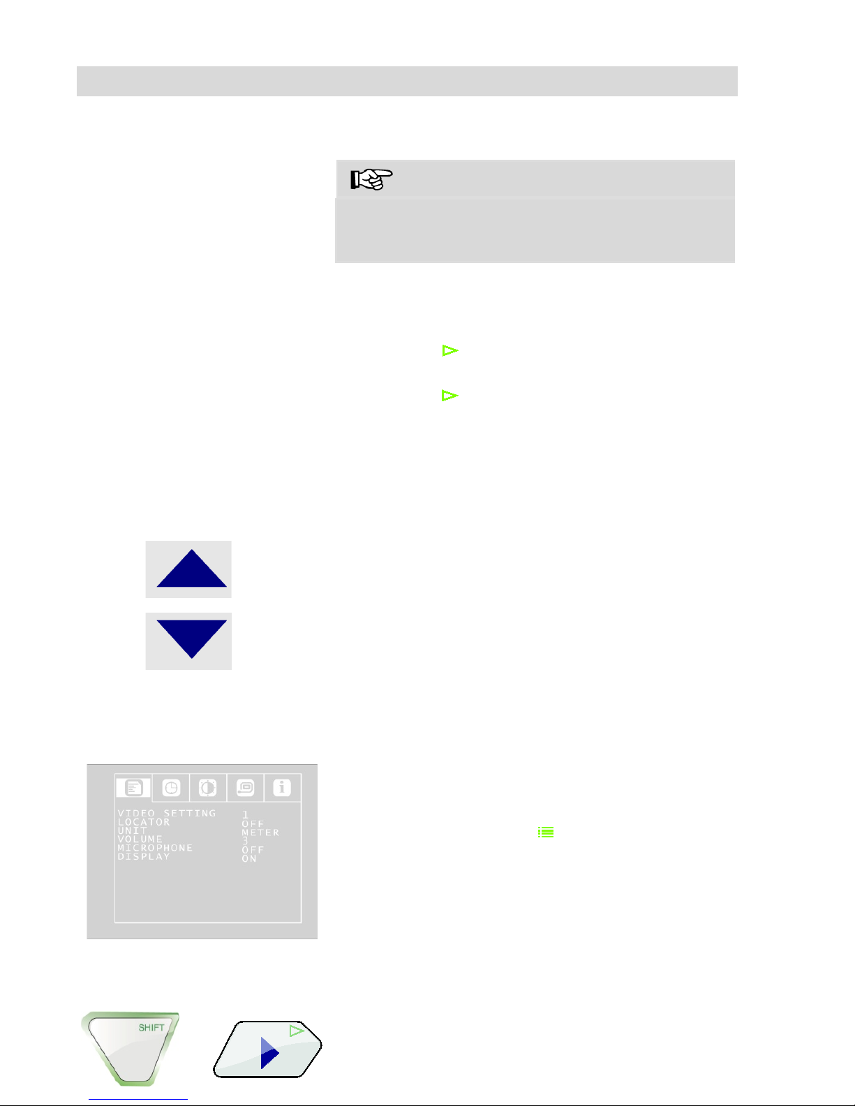
• To playback a recorded video, press the
SHIFT key and then the PLAY key. The first
image of the last video recorded is displayed
+
Page 35
Audio and video functions
35
on the screen.
NOTE!
It is possible to distinguish a photo from the initial
image of a video by the recording time which is
displayed in the initial image of a video.
Select the desired video using the right/left arrow
keys.
• To begin playing back the video, press the
Play key .
• To interrupt the video playback, press again
SHIFT +
• To stop the video playback press SHIFT + Left
arrow key
• Press the ON/OFF key to return to the normal
mode.
Fast- forward and rewind
• In play mode press the up arrow to fast for-
ward the video (double speed). 2x will appear
on screen.
• Press the up arrow again to forward the video
faster. 4x will appear on screen.
• Press the down arrow to return to double and
then to normal speed.
• In play mode press the down arrow to rewind
the video (double speed). 2x will appear on
screen.
Playing back an audio anno-
tation
Fig. 30: SETUP Menu
Any audio annotation will be played back together
with the video. It is possible to switch the sound off
to play the video without voice annotation, if you
select Volume = 0.
• Press the SHIFT key and then the Menu key to
access the Menu tab.
• Using the arrow keys, select VOLUME and set
0, 1, 2 or 3.
12.3 Delete files
• To select the file to be deleted (including the
+
Page 36
Capture images
36
audio file, if necessary), press the SHIFT key
and then the PLAY key.
The first image of the last video recorded is displayed on the monitor.
• Select the video to be deleted using the
right/left arrow keys.
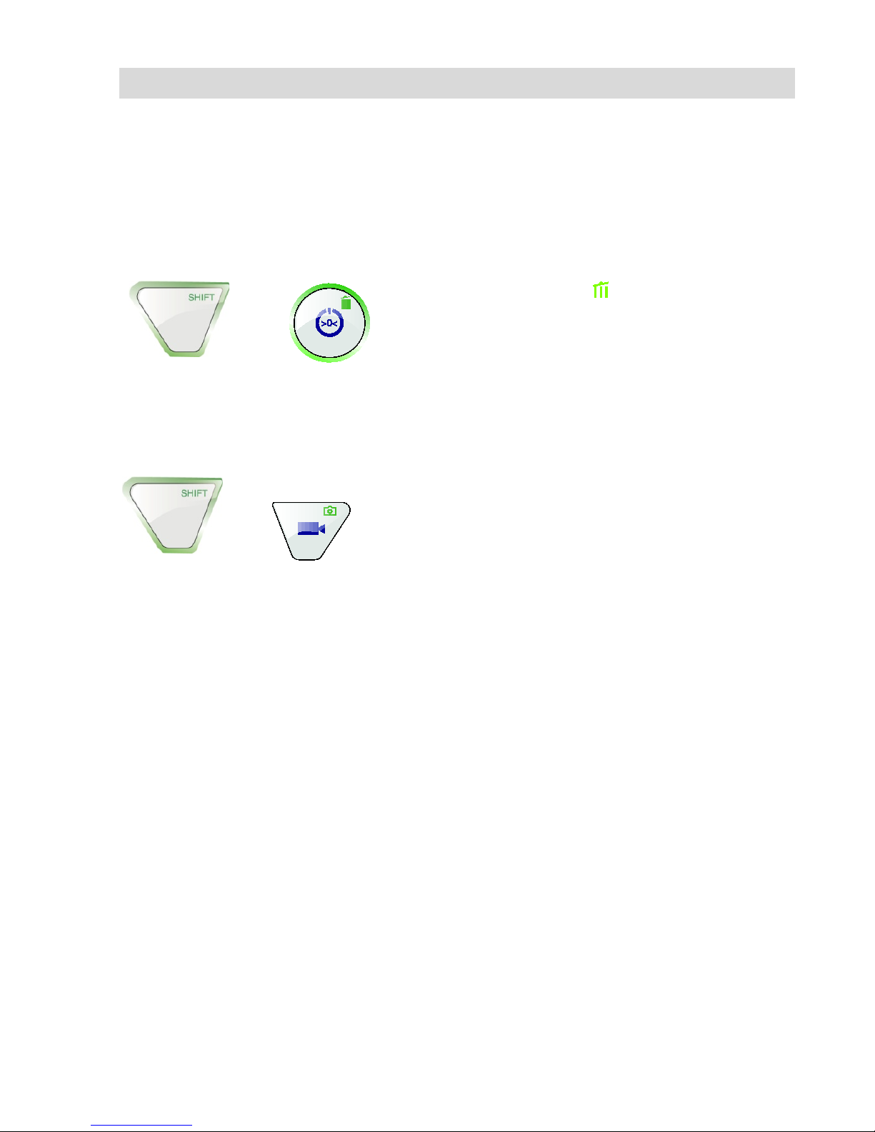
• To delete the video, press the SHIFT key and
then the DELETE key .
The prompt "DELETING FILE" is displayed on the
screen for approximately 2 seconds. Once the file
has been deleted, the image currently being
transmitted from the camera head is displayed on
the screen.
13 Capture images
• To capture an image, press the SHIFT key
and then the PHOTO key.
The image is saved as a .jpg file on the memory
card.
+
+
Page 37
Delete files
37
14 Delete files
• To select the file to be deleted (including the
audio file, if necessary), press the SHIFT key
and then the PLAY key.
The first image of the last video recorded or the
last image recorded is displayed on the monitor.
Note!
The recording time in the initial image of a video
shows that it is a video and not a photo.
• Select the video or the image to be deleted
using the right/left arrow keys.
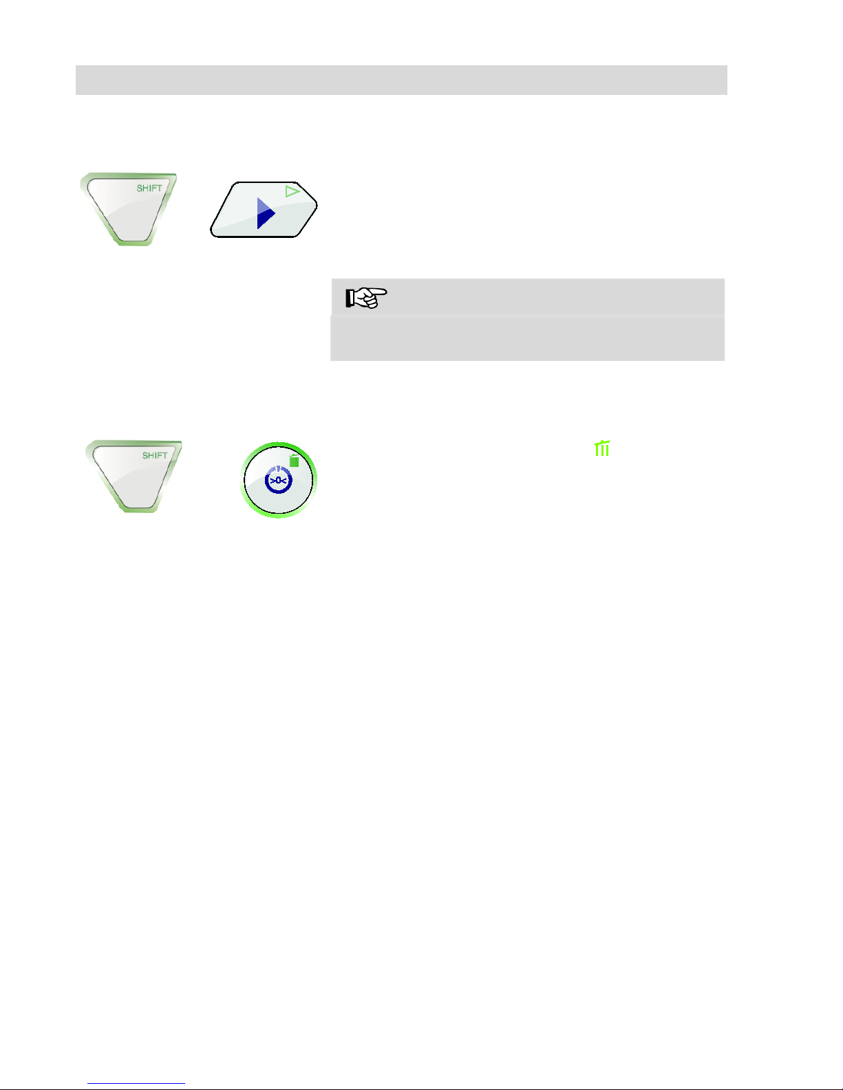
• To delete the video or image, press the SHIFT
key and then the DELETE key .
The prompt "DELETING FILE" is displayed on the
screen for approximately 2 seconds. Once the file
has been deleted, the image currently being
transmitted from the camera head is displayed on
the screen.
15 Transferring and showing images and videos
15.1 Transferring to the PC
Two options are available to transfer image files
(.jpg) and video files (ASF):
• Read in the files on a PC from the SD memory
card or
•
Transfer the files to the PC using the USB
cable.
15.2 Replaying videos on
the PC
To playback a video on the PC the Windows Me-
dia Player can be used.
+
+
Page 38
Guide accessories
38
16 Guide accessories
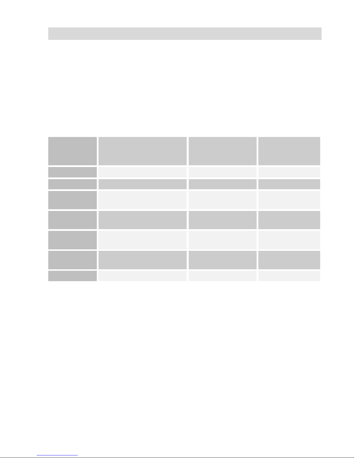
This section contains some recommendations based on our experience about the se-
lection of guide accessories for the inspection in tubes and ducts.
As all pipes and chimney systems are different, the user has to decide about the guide
accessory in every single case. For the selection of the correct tool it is important to
consider that the guide accessory has to facilitate the introduction and the extraction of
the camera head, as well as an adequate guidance. The danger of jamming or getting
stuck in the tube has to be avoided.
Pipe
Ø
Camera Head
Ø 26 mm
Camera Head
Ø 40 mm
Camera Head
Ø 51 mm
40
Without accessories
-
-
50
3827
-
-
60
3634, 3827, 3847
2641, 3682
Without
accessories
70
3634, 3827, 3847, 8894
2641, 3682, 8894
Without
accessories
100
3634, 3827, 3847, 8894,
3850, 3857
2641, 3682, 8894,
3850, 3857
3494, 3590
125
3634, 3827, 3847, 8894,
3850, 3857, 3681
2641, 3682, 8894,
3850, 3857, 3681
3681, 7826
150 x x
3855
Table: Appropriated accessories ( article numbers)
- Inspection not possible
x Every accessory possible
Page 39
Faults
39
17 Faults
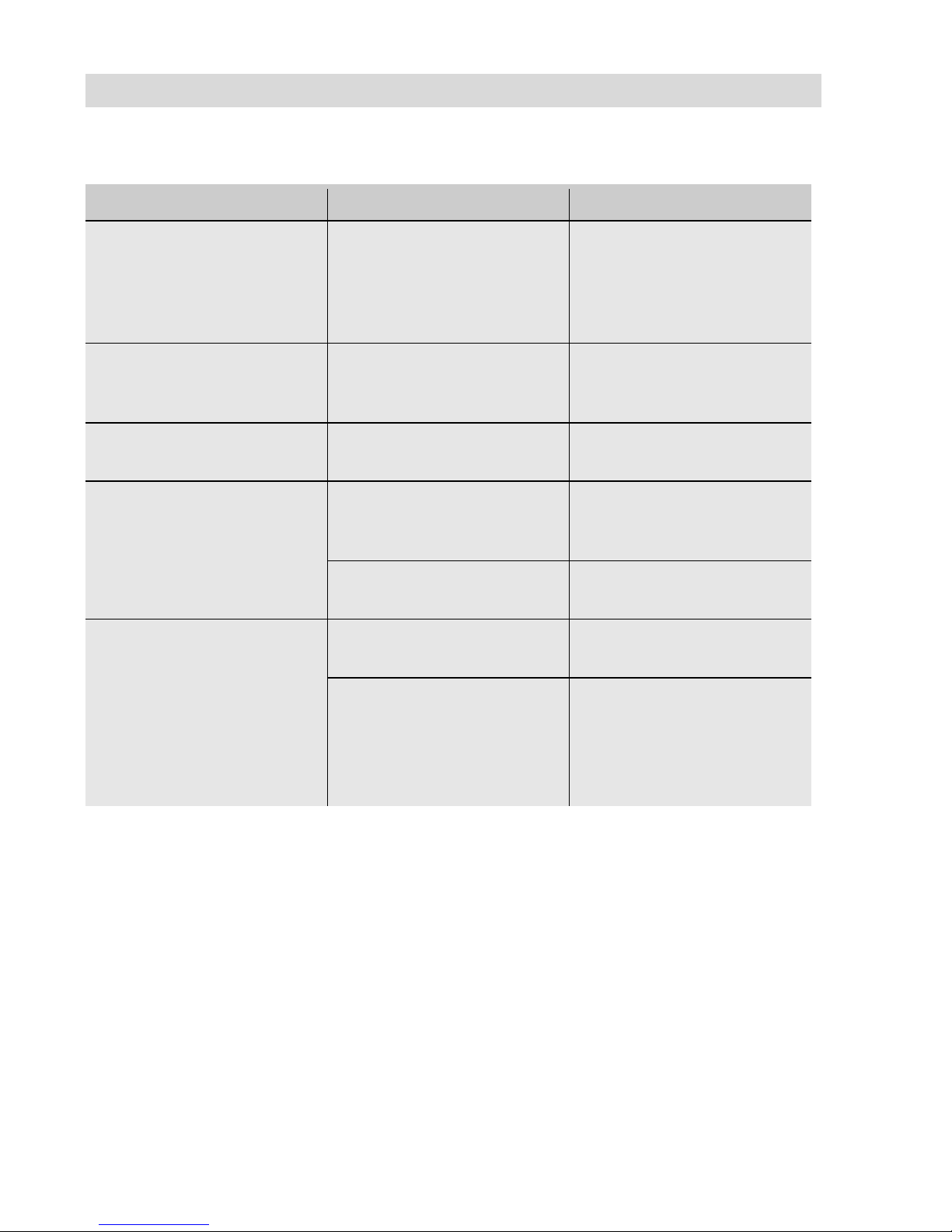
Fault description
Possible cause
To rectify
Cannot start monitor.
When the ON/OFF key is
pressed, the light framing
the key briefly lights up
red.
Rechargeable battery has
no charge left.
Recharge battery or con-
nect monitor to electrical
power supply
Battery status indicator on
the monitor indicates a low
battery charge.
Rechargeable battery has
no charge left.
Recharge battery or con-
nect monitor to electrical
power supply
Poor imagery when using
a pan&tilt camera head
Plastic dome scratched.
Replace the plastic dome;
glass dome optional.
Camera head or monitor
freezes
Battery has no charge left.
Recharge battery or con-
nect monitor to electrical
power supply
Device is faulty.
Send camera system in for
repair.
Blue screen, NO SIGNAL
displayed on the monitor
Rod is broken.
Send camera system in for
repair.
Cable/plug connection at
monitor not properly connected.
Reconnect the plug con-
nection.
Broken cables in plug
connection. Send camera
system in for repair.
Page 40
Maintenance
40
18 Maintenance
18.1 Replacing the dome of
the camera head
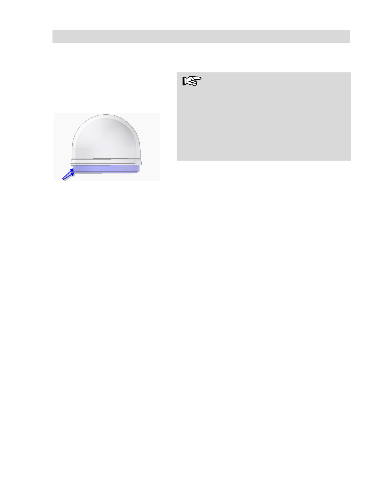
Fig.
31: Fitting the camera dome
NOTE!
Wöhler's Ø 40 mm pan&tilt camera head is supplied ex-works protected by a plastic dome, which
can be replaced if necessary. If it becomes
scratched, i
t is optional to fit this camera head with
a glass dome for use in dry working environments.
The Ø 51 mm camera head is always supplied
with a real glass dome, which it is possible to replace if required!
Apply silicone grease before fitting the new dome.
When fitting the replacement dome, make sure
you cover all of the thread to ensure it is properly
tightened. Otherwise, it cannot be guaranteed that
the camera head is properly sealed, and malfunctions can occur as a result of water and dirt penetration.
18.2 Monitor
Clean the monitor using a soft cloth.
19 Warranty and service
19.1 Warranty
Each Wöhler VIS 400 Colour Monitor will be test-
ed in all functions and will leave our factory only
after extensive quality control testing.
If used properly, the warranty period for the VIS
400 Colour Monitor will be 12 month from the date
of sale. Not covered by the warranty are components subject to wear, e.g. batteries.
This guarantee does not include the costs for
transport and packing material in case of repair.
Service by non authorized personnel or making
modifications on the service camera voids any
warranty.
19.2 Service
Wöhler has built our reputation on excellence in
customer service. Therefore, of course, we are
readily available to assist you after the guarantee
period ends.
•
Send us the camera system, and we will repair
it and return it to you with our package service.
•
Immediate help is provided by our technical
staff over the telephone.
Page 41

Accessories
41
20 Accessories
Wöhler Camera Head Colour Ø 51 mm, pan and tilt
Order no. 7806
Wöhler Camera Head Colour Ø 40 mm, pan and tilt
Order no. 8930
Wöhler Miniature Camera Head Colour Ø 26 mm
Order no. 8920
Wöhler Cable Reel Wöhler VIS 400
Order no. 7816
Wöhler Camera Viper 42 with GRP camera rod
Order no. 7307
Wöhler VIS Guidance Set 100
Order no. 3884
Wöhler VIS Guidance Set 150
Order no. 3882
Wöhler Camera Roller Guide
Order no. 3681
Guidance Sleeve with protection cage for camera head Ø 26 mm
Order no. 3847
Wöhler Guidance weight
Order no. 3857
Wöhler Guidance ball
Order no. 3634
Quick Charger 2,5 A / 230 V / 50 HZ
Order no. 56102
Wöhler Protection sleeve for camera head Ø 40 mm
Order no. 3682
Wöhler Replacement Glass Domes Ø 51 cm
Order no. 3494
Wöhler Glass Dome Ø 40 mm
Order no. 3674
Wöhler Glass Dome Ø 51 cm
Order no. 7802
Wöhler Replacement Plastic Domes Ø 51 cm (5 pieces)
Order no. 7075
Wöhler Replacement plastic domes Ø 40 mm (10 pieces)
Order no. 3675
Wöhler Additional Illumination, plug-in type
Order no. 4194
Page 42

Declaration of conformity EG
42
21 Declaration of conformity EG
WÖHLER Technik GmbH
Wöhler-Platz 1, D-33181 Bad Wünnenberg
Declares that the following product:
Complies with the safety requirements set out in the directives of the European parlia-
ment and council on the approximation of laws of the Member States relating to electromagnetic compatibility (2014/30/EU) and low voltage (2014/35/EU).
The following standards were used to access the products in terms of electromagnetic
compatibility.
Page 43

Points of sale and service
43
Points of sale and service
Wöhler Technik GmbH
Wöhler-Platz 1
33181 Bad Wünnenberg
Tel.: +49 2953 73-100
Fax: +49 2953 73-96100
[email protected]
www.woehler.de
Wöhler South
Gneisenaustr.12
80992 Munich
Tel.: +49 89 1589223-0
Fax: +49 89 1589223-99
[email protected]
Wöhler West
Castroper Str. 105
44791 Bochum
Tel.: +49 234 516993-0
Fax: +49 234 516993-99
[email protected]
International
USA
Wohler USA Inc.
5 Hutchinson Drive
Danvers, MA 01923
Tel.: +1 978 750 9876
Fax.: +1 978 750 9799
www.wohlerusa.com
Italy
Wöhler Italia srl
Corso Libertà 9
39100 Bolzano
Tel.: +39 0471402422
Fax: +39 0471 406099
[email protected]
www.woehler.it
Czech Republic
Wöhler Bohemia s.r.o.
Za Naspern 1993
393 01 Pelhrimov
Tel.: +420 565 349 011
Fax: +420 565 323 078
[email protected]
France
Wöhler France SARL
31 Bis Rue Georges Ohnet
31200 Toulouse
Tel.: +33 5 61 52 40 39
Fax: +33 5 62 27 11 31
[email protected]
www.woehler.fr
Your contact:
 Loading...