

Page 1
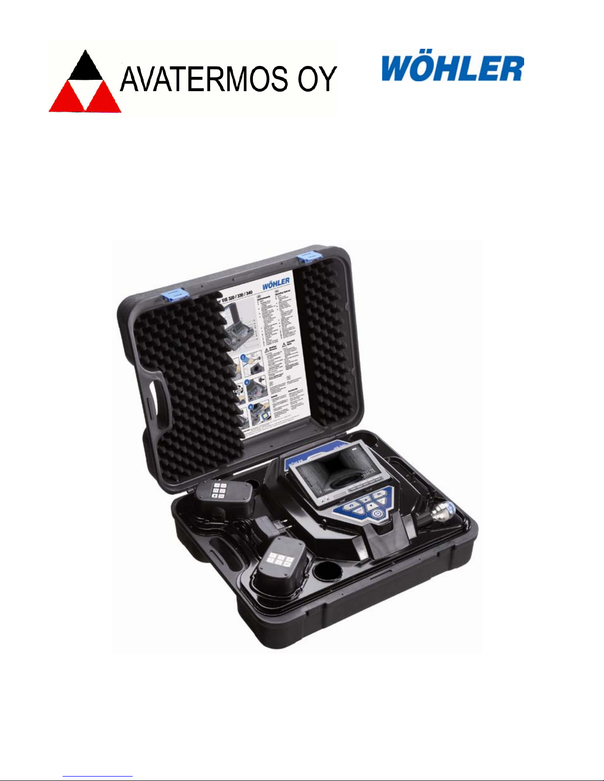
Operating manual
Service Camera
Wöhler VIS 2xx
Wöhler VIS 3xx
Best.- Nr. 22357 2012-08-03
Page 2

Contents
EN
Contents
1 General Information ........................... 31
1.1 Operation Manual Information ..................... 31
1.2 Notes ........................................................... 31
1.3 Intended Use ............................................... 31
1.4
Components ................................................ 32
1.5 Transport ..................................................... 32
1.6 Information on disposal ................................ 33
1.7,PSRUWer ................................................ 34
2 Specifications ..................................... 34
2.1 Monitor ......................................................... 34
2.2 Color Camera Head ..................................... 35
2.3 Camera head, pan and tiltable ..................... 35
2.4
Rod .............................................................. 35
2.5 Storage (VIS 240 / VIS 340) ....................... 36
3 Component explanati o n ..................... 37
3.1 Versions ....................................................... 39
3.1.1
VIS 2xx ........................................................ 39
3.1.2 VIS 3xx ........................................................ 39
3.2
Camera Control ........................................... 40
3.3 Monitor ......................................................... 42
4 Getting started .................................... 43
4.1 Check battery status .................................... 43
5 Working with the camera ................... 44
5.1 Turning the camera and the monitor on ....... 44
5.2 Important notes ............................................ 44
6 Changing the camera head and the
dome
..................................................... 46
6.1 Changing the dome of the colour camera head
VIS 3xx
........................................................ 46
6.2 Exchanging the camera head VIS 230 / 330
(with locator)
................................................ 46
7 Setting Date and Time (VIS 240 /340) 47
8
Play videos at PC ................................ 48
Page 3

Contents
30
8.1
Installati on VLC-Viewer ............................... 48
8.2 Create frames ............................................. 48
8.3
Snapshotlist ................................................. 48
9 Guide conducts VIS 2xx / VIS 3xx ..... 49
10
Troubleshooting .................................. 50
11
Maintenance ........................................ 51
12
Warranty and service ......................... 52
12.1 Warranty ...................................................... 52
12.2 Service ........................................................ 52
13 Accessories ......................................... 53
14
Declaration of confor m ity EC ............ 54
Page 4

General Information
31
EN
1 General Information
1.1 Operation Manual In-
formation
This operation manual allows you to safely work
with the Wöhler VIS 2xx / 3xx service camera.
Please keep this manual for your information.
The Wöhler VIS 2xx / 3xx service camera should
be used by trained professionals for its intended
use only.
Liability is void for any damages caused by not
following this manual.
1.2 Notes
WARNING!
Not following this warning can cause injury or
death.
ATTENTION!
Not following this note can cause permanent
damage to the analyzer.
NOTE!
Usefull information
1.3 Intended Use
Do not use the Wöhler VIS 3xx / 2xx for any other
use than set out in this manual.
Use the Wöhler VIS 3xx / VIS 2xx Service Cam-
era for the inspection of pipewor ks, dra ins and
sinks, such as exhaust systems, ductworks etc.
and for the documentation of damages.
Page 5

General Information
32
1.4 Components
Model
Components
VIS 2xx / 3xx
Heavy duty carrying
case
Push rod
Monitor
2 Replacement batter-
ies NiMH
1 Anti slide mat
Power supply
2 GB CF-Card
(VIS 240 / VIS 340)
Mini USB-cable
(VIS 240 / VIS 340)
VIS 2xx
Color camera head
VIS 3xx Pan & tilt color cam-
era head
5 Replacement glass
domes, extra
1.5 Transport
ATTENTION!
The camera should be transported in the original
carrying case only!
Page 6

General Information
33
EN
1.6 Information on dispos al
Electronic equipment does not belong into domes-
tic waste, but must be disposed in accordance
with the applicable statutory provisions.
You may hand in any defective batteries taken out
of the unit to our company as well as to recycling
places of public disposal systems or to sel li n g
points of new batteries or storage batteries.
Page 7

Specifications
34
1.7
,PSRrWHU
$YDWHUPRV2\
.LOORQWRULQWLH
333LUNNDOD
*VP
6lKN|SRVWLDYDWHUPRV#DYDWHUPRVIL
2 Specifications
2.1 Monitor
Fig. 1: Monitor
Description
Date
TFT - Display 7“ / 16:9 and 4:3
Weight
400 g
Casing size
176 x 114 x 32 mm
Video out
FBAS
Power Supply
1 x rechargeable
battery NiMh
Power
Power supply unit
Voltage
12 V
Operation temperature
0 – 40 °C
Storage temperature -20°C – 50°C
Page 8

Specifications
35
EN
2.2 Color Camera
Head
Fig. 2: Miniature camera head color
Description
Date
Type
1/3“ Color CCD
Sensitivity
0.5 Lux
Lens system
f = 2.31 mm, F = 2.4
Field of view 120°
Light source
12 white LEDs
Protection Waterproof acc. to
IP 68
Size 26 mm x 38 mm
2.3 Camera head, pan
and tiltable
Fig. 3: Camera head, pan- and tiltable
Description
Date
Typ
1/3“ Color CCD
Sensitivity 0.5 Lux
Lens system
f = 2.31 mm, F = 2.4
Field of view 120°
Light source
12 white LEDs
Protection
Waterproof acc. to
IP 67
Size 40 mm x 60 mm
2.4 Rod
Description
Date
Length
20 m
(Optional 30 m)
Diameter
6.5 mm (VIS 3xx)
6 mm (VIS 2xx)
Page 9

Specifications
36
2.5 Digital distance
measurement
(VIS
230/240/330/340)
Description
Date
Resolution
0.04 m
Max. discrepancy
10% of reading
2.6 Storage
(VIS 240 / VIS 340)
Description
Date
Memory card
max. 32 GB
(You must format the
card on the PC,
FAT 32.)
Capacity App. 1h / GB
Resolution
640 x 480 (VGA)/
max. 30 fps
Format
ASF (MPEG4)
Page 10
Component explanation
37
EN
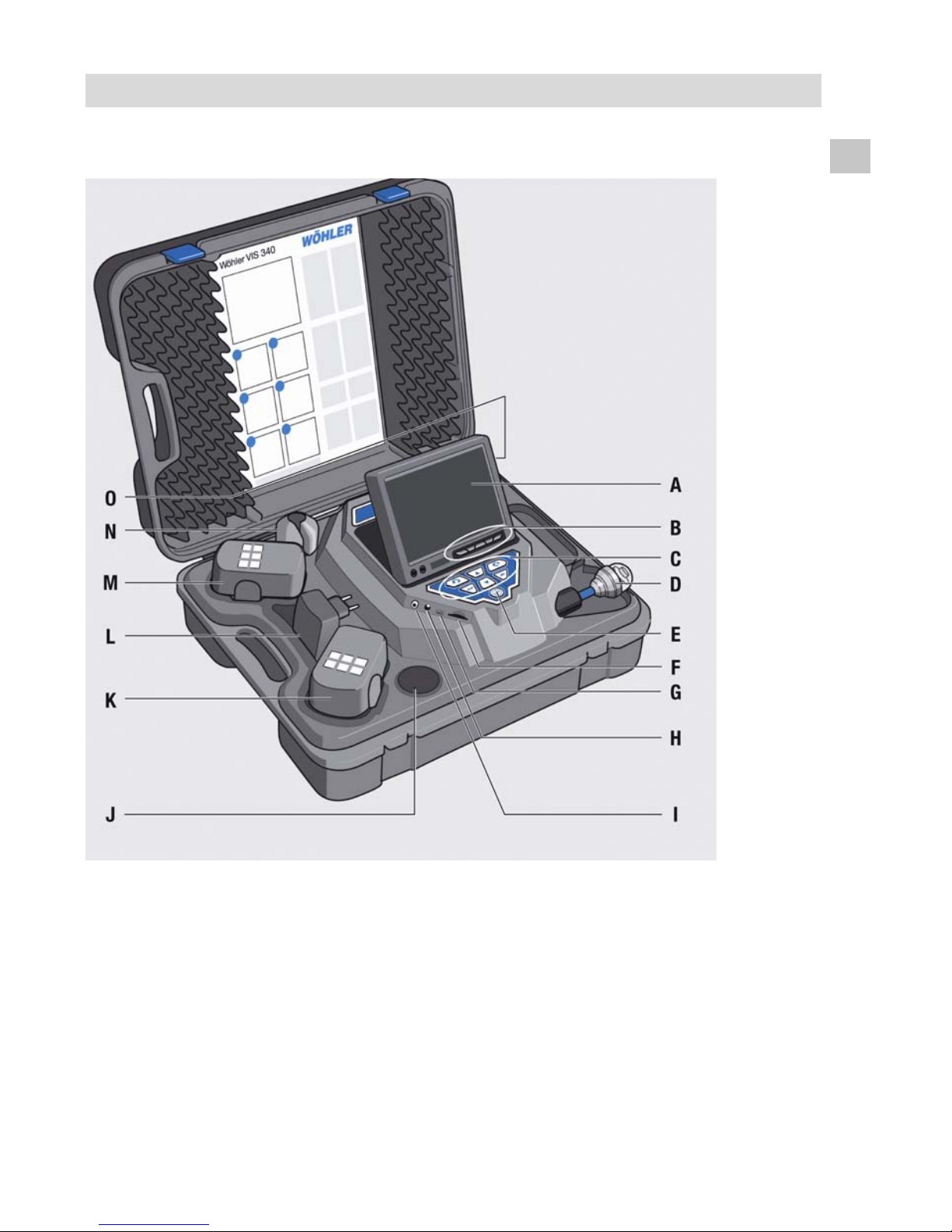
3 Component explanation
Fig. 4: VIS 3xx
Page 11

Component explanation
38
Component explanation:
A
Monitor
B
Monitor controls
- Brightness / contrast
- Color
C
Camera control (only VIS 3xx )
with record and play-function (VIS 240 / VIS 340)
D
Camera head, waterproof:
VIS 3xx: pan- and tiltable
Color camera head 40 mm Ø
VIS 2xx: Miniature color camera head 26 mm Ø
E
Main power switch with the following functions:
- ON / OFF (System)
- Battery and sy st em st atus
- Reset distance measurement (press shortly)
- Escape
F
Cardslot for memory card (VIS 240 / VIS 340)
G
Mini-USB-port (VIS 240 / VIS 340)
H
Power supply socket (18V/1,6A)
I
Video out
J
Accessory compartment 1
K
Rechargeable battery, extra
L
Power supply
M
Rechargeable battery, in use
N
Accessory compartment 2
O
Accessory compartment 3
Page 12

Component explanation
39
EN
3.1 Versions
The differences between the versions are as follows:
3.1.1 VIS 2xx
Equipment
- Miniature Camera head: 26 mm Ø
- VIS 220: Metric marked push rod cable
- VIS 230: digital meter counter (optional also
with Locator Wöhler LT 24
- VIS 240: Video file memory
Application area - Flue gas lines
- Air conditioning and heating lines
- Analysis of defects in waste water pipes (40
mm Ø and bigger)
- With the Lokator: 50 mm Ø and bigger
3.1.2 VIS 3xx
Equipment
- Camera head, pan- and tiltable
(360° panable and 180° tiltable camera eye)
40 mm Ø
- VIS 330: digital meter counter ( optional also
with Locator Wöhler LT 24)
- VIS 340: Video file memory
Application area
- Flue gas lines with a diameter greater than
60 mm Ø and bows of 87° and more.
- Chinmeys
- Exhaust systems
- Detection of problems in waste pipes with
70 mm Ø or bigger
Page 13
Component explanation
40
3.2 Camera
Control
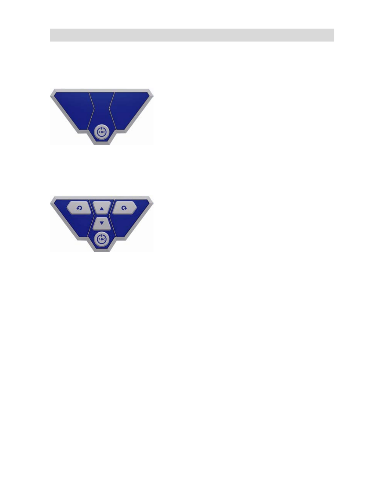
VIS 220 /230
Fig. 5:
Camera control VIS 220 / 230
The control panel includes the ON-/OFF-Key of the
camera system. When the camera is switched on and
the battery is completely charged, there will shine a
green ring around the ON-Off-Key.
While charging the battery, the ring will blink red and
after charging is completed, the lower part will shine
green.
Pressing the ON-/Off-key will turn on both the camera
system and the monitor (all versions).
VIS 330
Fig. 6:
Camera control VIS 330
The control panel includes the ON-OFF key of the
camera system and the control keys for the pan- and
tiltable camera head.
(The camera eye is 360° panable and 180° tiltable).
The center arrow keys control the 180° tilting. With
the two outer keys the lens can be turned round 360°.
Page 14
Component explanation
41
EN
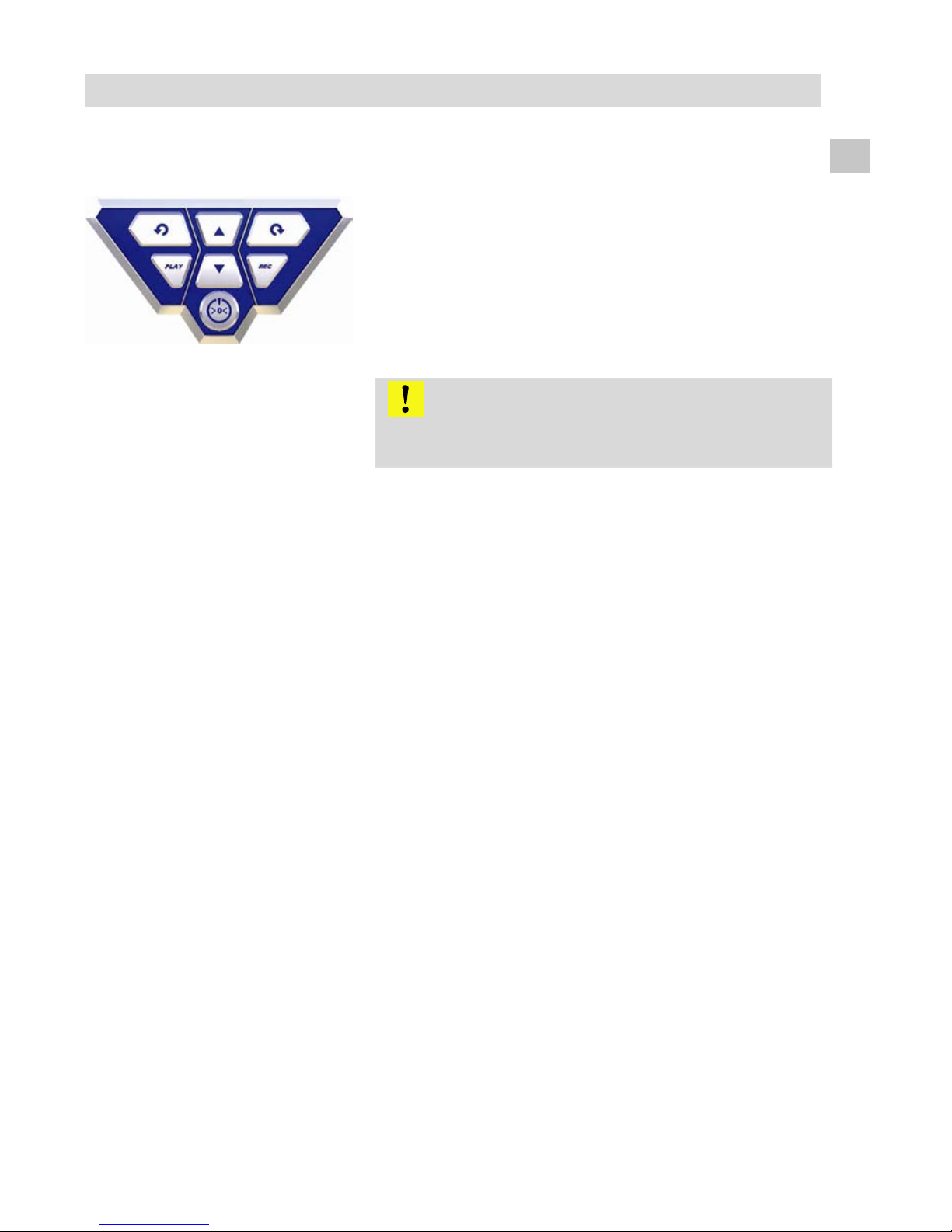
VIS 240 / 340
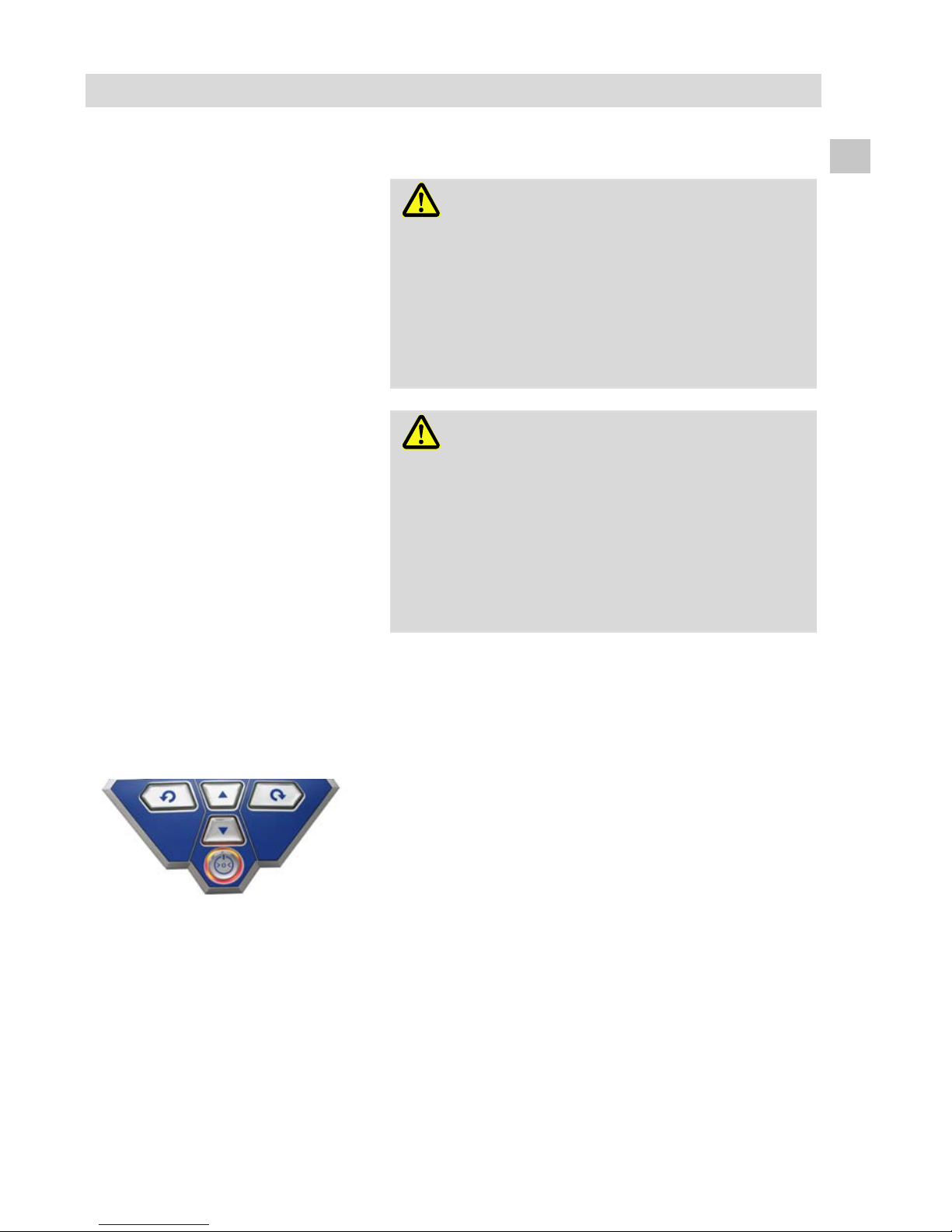
Fig. 7:
Camera control VIS 240 / 340
The camera eye is 360° panable and 180° tiltable.
(only VIS 340)
The center arrow keys control the 180° tilting. The two
outer keys turn the lens 360° (only VIS 240).
In the Play-mode, the two outer arrow keys are also
used for the menu navigation (VIS 240 and VIS 340).
The Rec-key starts and finishes the Video recording.
ACHTUNG!
Make sure that the power will not be disconnected
during the Video recording.
Press the Play-Key to play the stored video file.
Press ON-/OFF to stopp the play back.
Press the Rec-key two seconds to delete a selected
video file. On screen the note “Video deleted” will
appear.
Arrow keys: Selection of the video
Page 15
Component explanation
42
Functions of the ON-/OFF-key
Press
Functions
2 seconds System ON/OFF
shortly
Escape (play mode)
shortly Reset digital meter
counter
3.3 Monitor
3.3.1 Adjusting the Col o r
Monitor
VIS 2xx / VIS 3xx
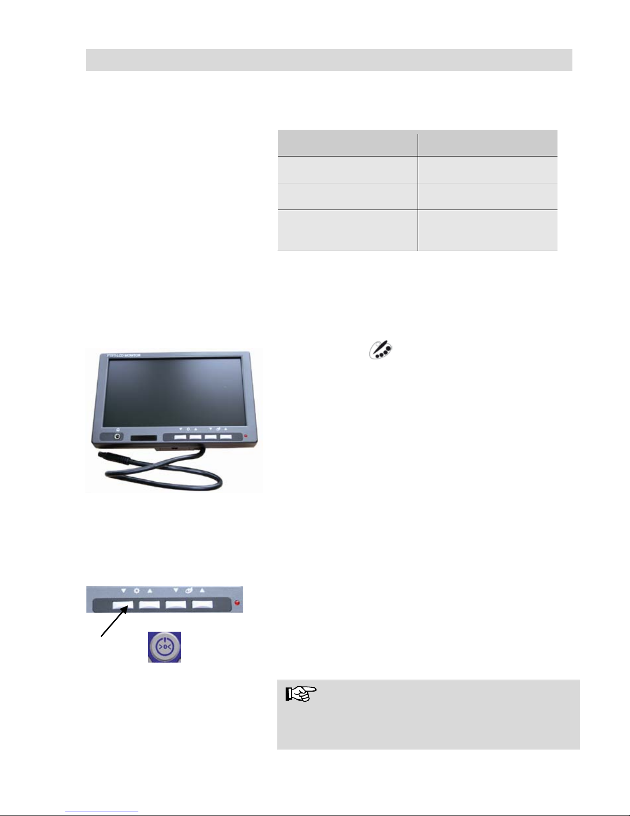
Fig. 8: Monitor
With the keys ▼☼▲ the brightness can be adjusted.
▼: darker ▲: brighter
With the keys ▼ ▲ the color intensity can be
adjusted
▼: decreasing color intensity up to bla ck and white
▲: increasing color intensity
3.3.2 Transition from 16:9 Screen to 4:3 Screen
If the monitor has the serial number 11010001, the screen format can be changed from
16:9 to 4:3 or vice versa. You will find the serial number on the back side of the monitor.
• Switch off the camera system.
• Press the left monitor key and the on/off-key of
the camera at the same time.
The screen format has now changed from 4:3 to
16:9 or vice versa.
NOTE!
When inspecting tubes the 4:3 screen is recommended, because the widescreen 16:9 may distort
the image.
Page 16
Getting started
43
EN
4 Getting started
4.1 Check battery
status
WARNING!
Incorrect use of batteries can cause injury!
Do not expose batteries to fire or high temperatures, that will cause danger of explosion!
Liquids can pore out of the batteries due to mistreatment. Never touch the liquid. If you got in
contact to the liquid remove it with water and see
your doctor as soon as possible.
WARNING!
Risk of electrical shock!
Never touch the recharger with wet hands!
Protect the recharger against water and moisture!
Do not unplug the recharger by pulling the cable!
Do not use the recharger when the voltage re-
quirements of the recharger and the suppl
y do not
match!
When the monitor indicates a low battery status,
Battery Level Indicator
Fig. 15: Bordero f the ON/OFF key flash-
es red
While the camera is turned on, a battery level
indicator will be displayed in the upper right-hand
corner of the display. It flashes to indicate low
power. When the power gets lower, the border of
the ON/OFF-key will flash red and the camera will
turn off automatically.
The camera can only be turned on again, after the
battery has been changed or the power supply
unit has been connected for charging. .
Page 17
Working with the camera
44
Charging the batteries
Charge the batteries as follows:
Before you plug the power supply unit into the
outlet, connect it with the camera system.
During the charging process the lower part of the
border around the ON-/Off-key will blink red. After
the charging process has finished it is highlighted
red.
5 Working with the camera
5.1 Turning the camera and the monitor on
VIS 2xx / 3xx
• Install the memory card (max. 32 GB)
Note!
It is necessary to format the card on the PC first
(FAT 32).
• Turn on the camera system by pressing the
ON/OFF-key.
5.2 Important notes
Strong electric or magnetic
fields
WARNING!
Do not expose the camera to strong electric or
magnetic fields as caused by television towers,
mobile radio units etc., because they may cause
image interferences.
Exterior influences
WARNING!
Exterior influences as statical discharges may
cause
dysfunctions. In this cas e swit ch the camer a
off and on.
Page 18

Working with the camera
45
EN
Push rod
- Push and pull smoothly
- Do not exceed rod end limit
- Do not bend or drag across sharp edges
WARNING!
Dry and clean the rod with a cloth, before pulling it
back, so that no dirt and soot can enter!
Carrying case
- Avoid any liquids getting inside the case.
- Do not drop the case.
Camera head
- Protect the lens of the camera head
against scratches.
NOTE!
Originally the camera head VIS 3xx is protected
by a plastic dome, which can be substituted by a
glass dome if necessary. Alternatively a glass
dome can be purchased that must be screwed
onto the camera head!
Page 19
Changing the camera head and the dome
46
6 Changing the camera head and the dome
6.1 Changing the
dome of the colour camera head
VIS 3xx
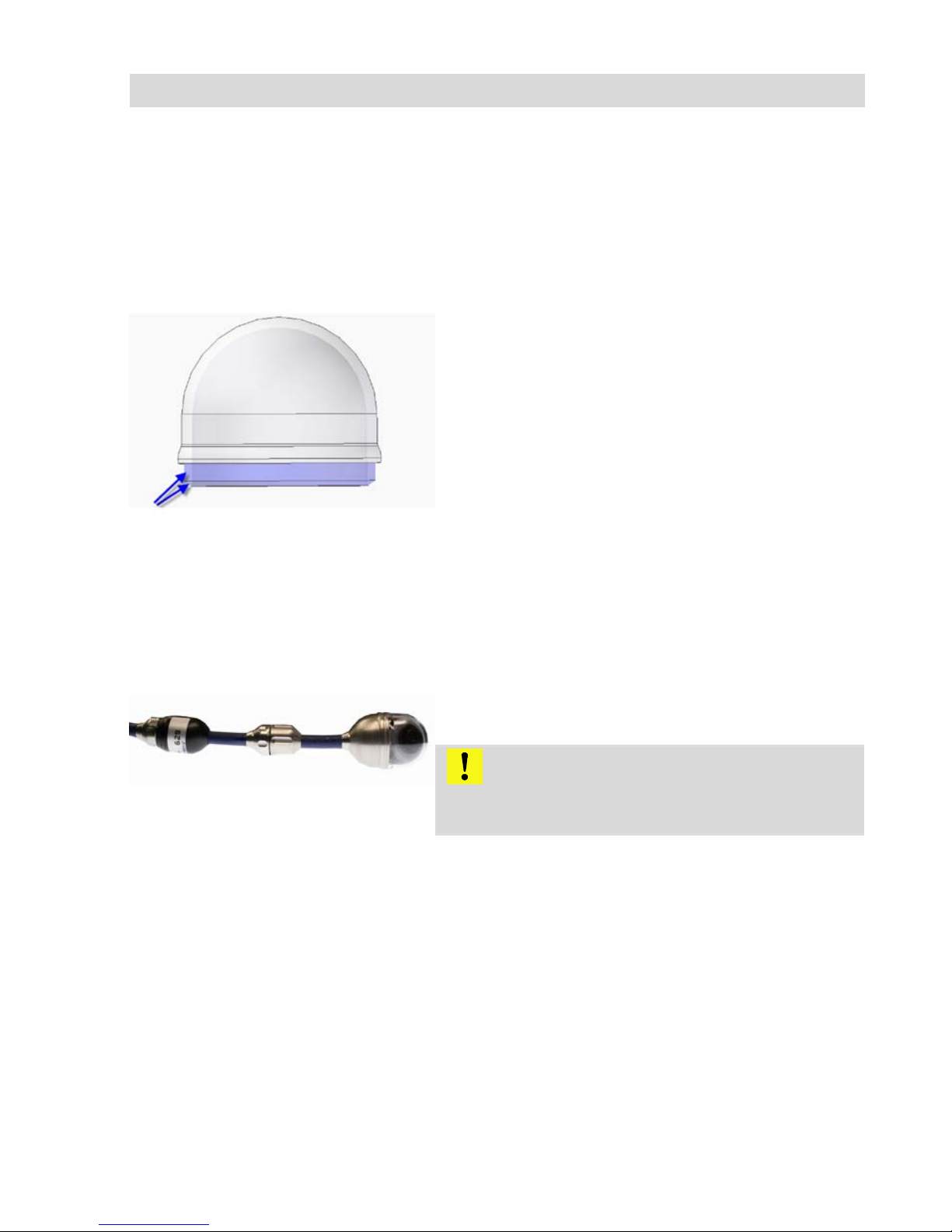
Fig. 9: Installing the dome
Before installing the new dome, grease the screw
thread slightly with silicone grease. Take care that
the dome is screwed firmly up to the last thread.
Otherwise the camera head will not be tight, and
water and dust can get inside.
6.2 Exchanging the
camera head VIS
230 / 330 (with locator)
Fig. 10: Camera head with locator
The rod end has a screw thread, so that the minia-
ture camera head and the pan- and tiltable camera head can be fixed and removed by screwing.
Take care to screw the rod and the camera head
firmly together, otherwise the assembly will not be
waterproof.
ATTENTION!
Only use your hands to screw the camera head,
but never a tong!
Page 20
Setting Date and Time (VIS 240 /340)
47
EN
7 Setting Date and Time (VIS 240 /340)
VIS 240 / 340
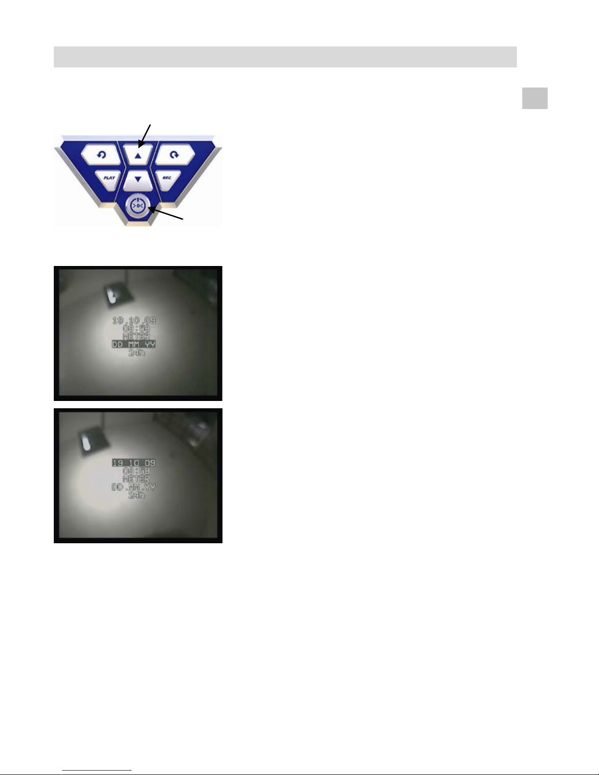
Fig. 11: Control panel VIS 240 / 340:
Press marked buttons simultaneously
• With the camera switched off, press the ▲ but-
ton and the ON-/OFF-button simultaneously for
two seconds.
Fig. 12: Setup Menu
The camera switches on and the display will show a
menu where the following setups can be done.
- Date
- Time
- Distance in Meter or Feet
- DD.MM.YY or DD/MM/YY
- 12 h or 24 h clock
• Move from one parameter to the other with the
arrow keys and change the values with the
▲/▼-keys.
• Press the ON-OFF-button to escape the menu.
Page 21
Play videos at PC
48
8 Play videos at PC
8.1 Installation VLC-
Viewer
• Insert CD. (The VLC Viewer is available as
freeware in the internet.)
• Click on Index.html. The menu will open.
• Click on the button “Install”.
• After the installation, the video files can be re-
played in the AFS/MPEG4 format.
8.2 Create frames
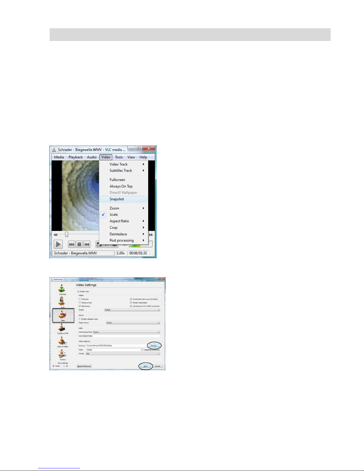
• To create a single frame of a video, click on
video > snapshot while running the video.
8.3 Snapshotlist
• Click on Tools > Preferences for storing.
• The window shown on the left will open.
• Select the Icon Video.
• Click on “Browse” and select the path where
you want to store your snapshot. You can select the file format (png or jpg) and add your
own prefix to the filename.
• Click on “Save”.
As the programm is a freeware (“Open Source”)
Wöhler cannot provide any technical support. You
will find more information as well as the current
version on the Website of the softwaremanufactor
www.videolan.org
Page 22
Guide conducts VIS 2xx / VIS 3xx
49
EN
NOTE!
As an alternative to the VLC Player you can use the”Daum PotPlayer“ to regard the
videos. You can download the Daum PotPlayer as freeware from the internet.
9 Guide conducts VIS 2xx / VIS 3xx
This chapter contains some recommen dations based on our experience about the se-
lection of guide conducts for the inspection in tubes and ducts.
As all tubes and chimney systems are different, the user has to decide about the guide
conducts in every single case. For the selection of the correct tool it is important to
consider that the guide conduct has to facilitate the introduction and the extraction of
the camera head, as well as an adequate guidance. The danger of jamming or getting
stuck in the tube has to be avoided.
NOTE!
The information given in this chapter only refers to the accessories. Chapter 3.1 explains which camera system can be used in which tube.
Ø 40 - 50 mm
Use the service camera without accessories.
Ø 50 – 70 mm You can use the service camera without accessories. The
lens can be protected by the guidance sleeve. If there is
water and mud in the horizontal part, we recommend to use
the roller guide.
Ø 70 – 100 mm The inspection is possible with the roller guide and without
it. Use the guidance weight for the vertical inspection or for
the inspection of downpipes.
Ø 100 – 154 mm
A centering brush can be used with the roller guide or with-
out it and with the lens protection.
Page 23

Troubleshooting
50
10 Troubleshooting
Problem
Possible reason
Solution
The battery level indicator
shown in the display indicates a low battery status.
Rechargeable batteries
are empty.
Replace or recharge bat-
teries.
The monitor is off, but the
LEDs of the camera head
are shining.
The monitor is not con-
nected correctly.
Plug in the monitor plug.
Monitor displays black and
white.
Minimal color intensity is
set.
Adjust the color intensity
of the monitor (see chapter 3.3)
▲:
VIS 3xx: Bad image Plastic dome is scratched. Change the plastic dome
(Option: Glass dome).
Camera or monitor do not
react.
Disposable or rechargeable batteries are empty.
Replace or recharge batteries.
The camera system is
damaged.
Send the device in for
repair.
The monitor display is
blue and the message NO
SIGNAL appears.
The rod is broken.
Send the device in for
repair.
The monitor is not con-
nected correctly.
Connect the monitor cor-
rectly.
The connection cable is
broken. Send the device
in for repair.
VIS 230 / 330: The color
camera head is not connected correctly to the
locator.
Attach the changeable
color camera head again.
Page 24

Maintenance
51
EN
11 Maintenance
Regular maintenance
Proper operation of the VIS 2xx / 3xx requires
regular maintenance. The following maintenance
works can be done by the user himself.
Camera head
Only use soft, damp cloth to clean the lens. Never
use any cleanser.
Push rod
Regularly pull the rod out of the case and clean it
with a soft, damp cloth.
Monitor
Use soft, dry cloth to clean the monitor.
Page 25

Warranty and service
52
12 Warranty and service
12.1 Warranty
Each Wöhler VIS 2xx / 3xx will be tested in all
functions and will leave our factory only after extensive quality control testing.
If used properly, the warranty period for the VIS
2xx / 3xx will be 12 month from the date of sale.
Not covered by the warranty are the batteries and
the plastic dome VIS 3xx.
This guarantee does not include the costs for
transport and packing material in case of repair.
Service by non authorized personnel or making
modifications on the service camera voids any
warranty.
12.2 Service
Wöhler has built our reputation on excellence in
customer service. Therefore, of course, we are
readily available to assist you after the guarantee
period ends.
• Send us the device, and we will repair it and
return it to you with our package service.
• Immediate help is provided by our techn ical
staff over the telephone.
Page 26

Accessories
53
EN
13 Accessories
Wöhler VIS Guidance Set 110 for VIS 3xx
Order No. 3884 J
Wöhler VIS Guidance Set 70 for VIS 2xx
Order No. 3883 J
Wöhler VIS Centering Brush Extension
Order No. 3853 J
Wöhler VIS Centering Brush Order No. 3854 J
Camera Roller Guide VIS 3xx Order No. 36 81 J
Wöhler VIS Stabilisation Tub e
Order No. 21736 J
Guidance Weight, stai nle ss steel
Order No. 3857 J
Guidance Ball
Order No. 3634 J
Wöhler Quick Charger 2,5 A / 230 V / 50 HZ
Order No. 56102 J
Spare Battery NiMh tested
Order No. 3715 J
Protection Sleeve for Wöhler VIS 3xx Order No. 3682 J
Glass Dome Order No. 3674 J
Replacement Plastic Domes (10 pcs.)
Order No. 3675 J
Anti Slide Mat
Order No. 56037 L
Wöhler Supplementary Light Ring with white LEDs
Order No. 9377 P
Wöhler Side View Mirror for the VIS 2xx
Order No. 7923 J
Pocket Multimediarecorder with AV- IN
Order No. 3726 L
Wöhler VIS Centering System (24 pcs.) Order No. 3858 J
Guidance Sleeve for VIS 2xx Order No. 3827 J
Guidance Sleeve with Protection Cage for VIS 2xx
Order No. 3847 J
Page 27

Declaration of conformity EC
54
14 Declaration of conformity EC
WÖHLER Messgeräte Kehrgeräte GmbH
Schützenstr. 41, D-33181 Bad Wünnenberg
Declares that the following product:
Name: Wöhler Service Camera
Model: Wöhler VIS 2xx / 3xx
Complies with the safety requirements set out in the directives of the European parliament and council on the approximation of laws of the Member States relating to electromagnetic compatibility (204/108/EC) and low voltage (2006/95/EC).
The following standards were used to access the products in terms of electromagnetic
compatibility.
EN 55024
EN 55022 Class B
 Loading...