

Page 1
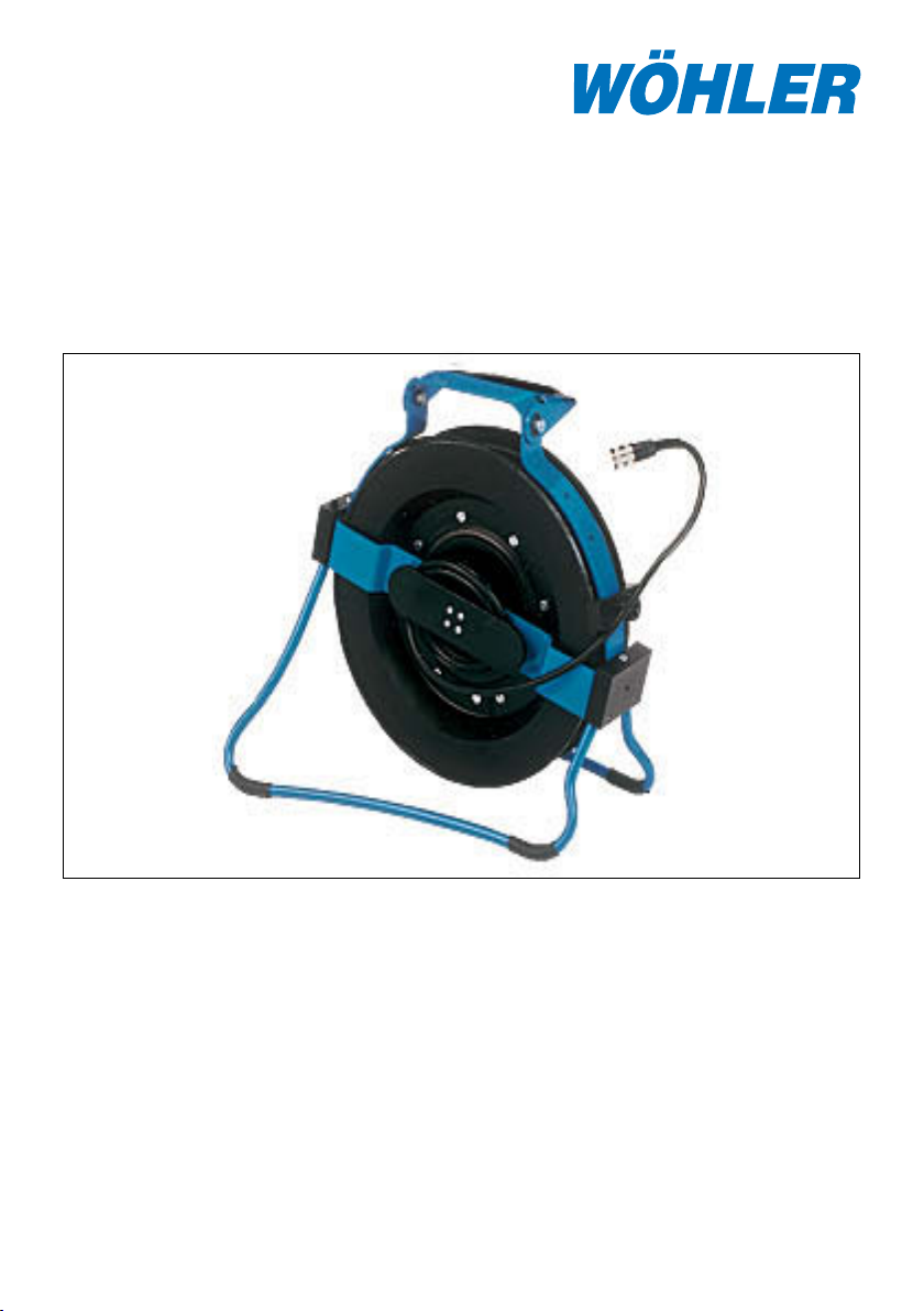
Kabelaufwicklung VIS 2000
mit digitaler Meterzählung
Inhalt
1. Spezifikation ................................... 2
2. Bedienung .......................................3
3. Kabelwechsel ..................................5
4. Führungswechsel bei der Inspektion. 6
25.03.2010 Art. Nr. 21643
Technik nach Maß
5. Hinweise zu Wartung und Pflege 7
6. Systemkomponenten ..................8
7. Zubehör/Ersatzteile ...................13
8. Konformitätserklärung ...............15
9. Garantie und Service .................16
Page 2

2 Hotline: 0 29 53 / 73 211 Fax: 0 29 53 / 73 250
Kabelaufwicklung VIS 2000
1. Spezifikation
1. Spezifikation
Das Videoinspektionssystem VIS 2000 ermöglicht die optische Kontrolle und
Dokumentation in Rohren und Schächten, z.B. Abgasanlagen, Lüftungsanlagen,
Abwasserrohren, etc. Das breite Spektrum der untereinander kompatiblen Systemkomponenten bietet die Auswahl einer individuellen und sehr gut auf die jeweilige
Aufgabe abgestimmten Kamerazusammenstellung.
Die hier beschriebene Kabelaufwicklung VIS 2000 dient dem bequemen Transport
und der komfortablen Handhabung des bis zu 30 m langen Kamerakabels während
der Inspektion.
Darüber hinaus bietet die Kabelaufwicklung eine für Transport und Inspektion verstellbare Halterung zur Aufnahme der Monitor- und Steuereinheit, eine integrierte
digitale Meterzählung zur Kabellängenmessung, einen komfortablen 4-Punkt-Tragegurt, eine Kabelbremse sowie einen Klappfuß. Sie ist hervorragend einzusetzen
bei der Inspektion von vertikalen Rohrleitungen wie Schornsteinen oder Fallrohren
und von Schächten etc. von oben. Mit heruntergeklappter Monitoreinheit inkl.
Kamerakopf-Köcher sowie eingeklapptem Fuß entsteht eine kompakte, vollständige Videoinspektionseinheit, die am Traggriff oder mittels Tragegurt bequem zum
Einsatzort transportiert werden kann. Mittels 4-Punkt-Tragegurt kann die Einheit
vor Ort mit ausgeklapptem Monitor vor dem Körper getragen werden, so dass beide Hände für die Bedienung von Monitor und Kabel/Kamerakopf frei bleiben. Zur
Bedienung auf dem Tisch oder dem Boden kann der Klappfuß breit ausgeklappt
werden, so dass ein sicherer Stand erreicht wird. Eine eingebaute Kabelbremse
dient der Sicherung des Kamerakopfes am Kabel.
Die integrierte Meterzählung mit einer hohen Auflösung von 0,05 Metern und einer
NullTaste ermöglicht eine genaue Positionsbestimmung der Schadstelle sowie
Abstandsmessungen im Rohr.
1.2 Technische Daten
Maße zusammengeklappt:
Höhe: 34 cm
Breite: 35 cm
Tiefe: 10 cm
Gewicht: 2,5 kg (ohne Kabel)
Max. Kabellänge: 30 cm
Integrierte Meterzählung:
Funktionsprinzip: digital
Auflösung: 0,05 m
Messbereich: 0 - 30,00 m
Bedien-Taste: Nullstellung, Parametereingabe
Bereitschaftsanzeige: LED
Page 3
2. Bedienung
2. Bedienung
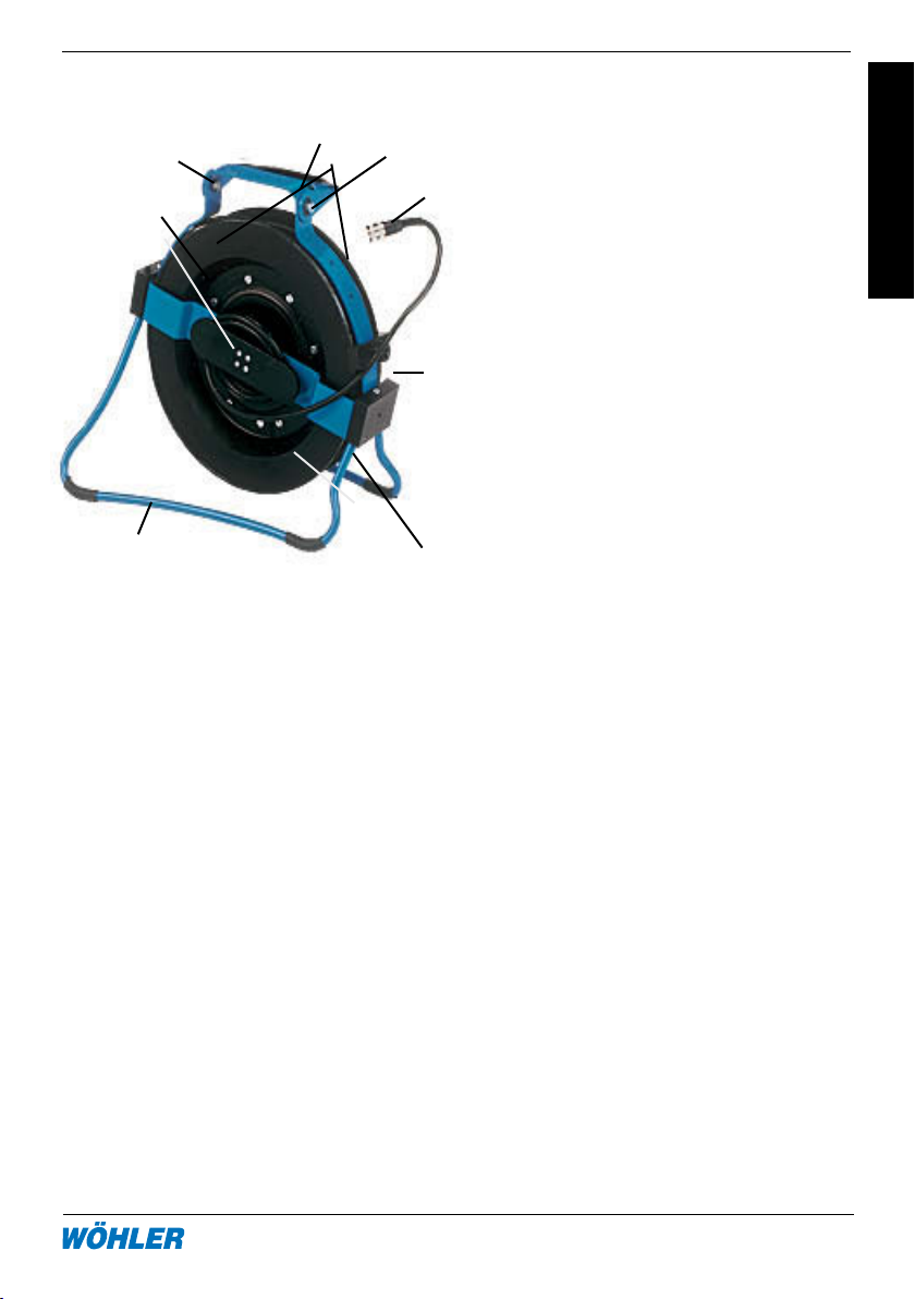
2.1 Bedienelemente
5
9
1
3
Abbildung 2.1 Foto Foto
ändern
2.2 Handhabung des Gerätes
4
7
2
10
1 Bedientaste
8
(Nullstellung während der
Messung, Parametereinstellung bei Einziehung eines
neuen Kabels)
2 Kabeltrommel
3 Klappfuß
6
4 Monitorhalterung mit Klapp-
möglichkeit
5 Traggriff
6 Bremse (Rückseite)
7 Anschlussmöglichkeit
4-Punkt-Gurt
8 Kabelanschluss zum Monitor
9
9 Befestigung Monitoranschluss
kabel (Rückseite Mitte)
10 Einstellknopf zum Ändern der
Position der Monitorhalterung
2.2.1 Anschluss der Kameraköpfe
Alle Kameraköpfe verfügen über eine 8-polige Kupplungs-Buchse, über die sie
mit dem Kamerakabel der Kabelaufwicklung verbunden werden (8-poliger Kabelstecker).
Stecken Sie die Kupplungs-Buchse des Kamerakopfes auf den Kabelanschluss
des Kamerakabels und drehen Sie anschließend das Gewindestück an der Kabelaufwicklung zum Verschließen im Uhrzeigersinn.
2.2.2 Anschluss der Monitore
Zum Anschließen des Monitors klappen Sie zunächst die Monitorhalterung hoch
(Abbildung 1, Teil 4). Drücken Sie hierzu den Einstellknopf. (Abbildung 1, Teil 10).
Verbinden Sie nun die Monitorhalterung mit dem Stativanschluss des Monitors.
Danach verbinden Sie den Kabelanschluss der Kabelaufwicklung (Abb.1, Teil 8)
mit der Eingangsbuchse am Monitor.
Page 4
4 Hotline: 0 29 53 / 73 211 Fax: 0 29 53 / 73 250
Kabelaufwicklung VIS 2000
2. Bedienung
2.2.3 Inspektion vertikaler Rohrleitungen
Rohrleitungen wie Schornsteine oder Fallrohre lassen sich am besten von oben,
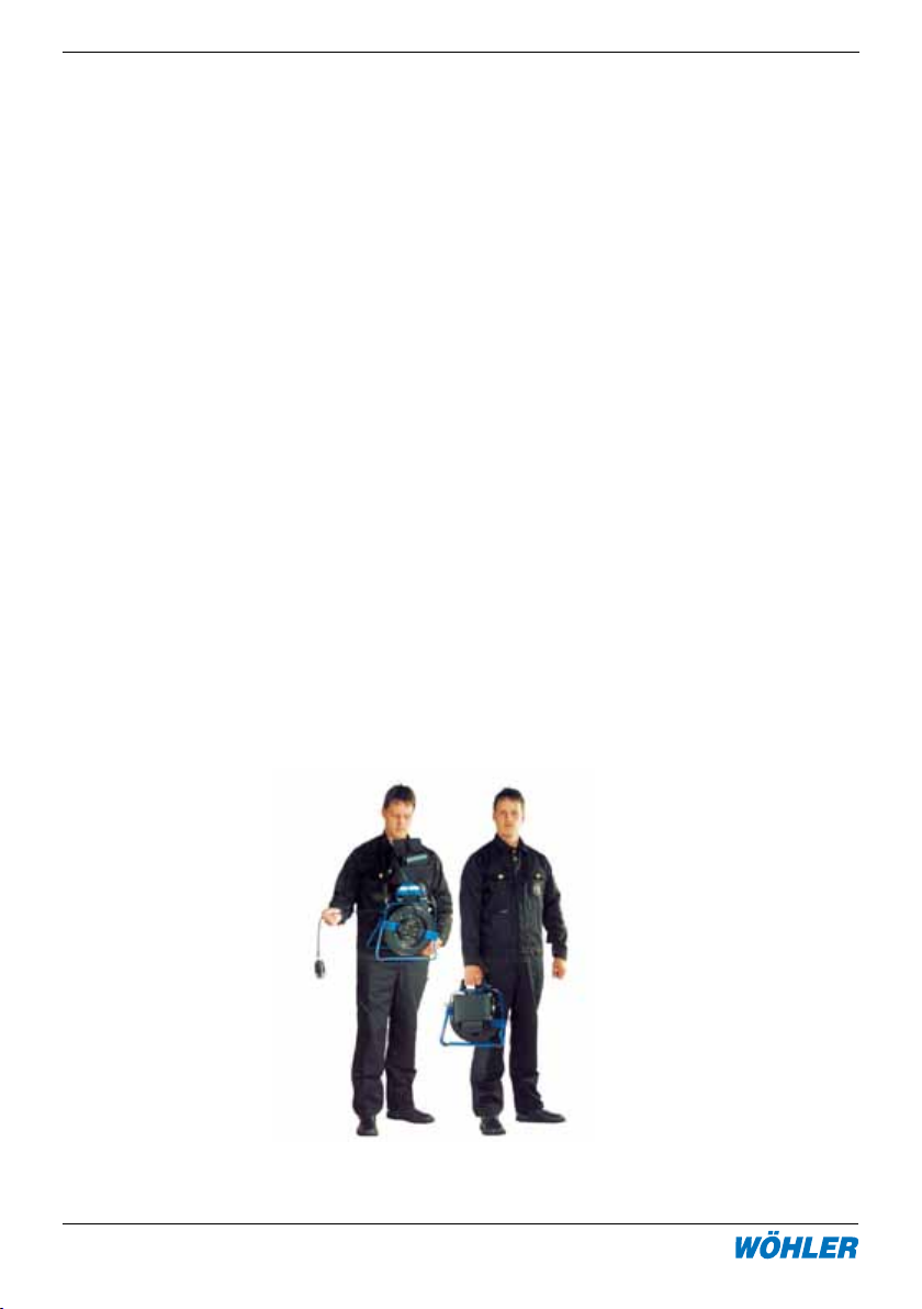
z.B. vom Dach aus inspizieren. Hierfür ist die Kabelaufwicklung ideal geeignet. Um
beide Hände frei zu haben, können Sie sie während der Inspektion vor dem Körper
tragen, indem sie den 4-Punkt-Tragegurt an den dafür vorgesehenen Stellen der
Aufwicklung befestigen. Klemmen Sie dazu die beiden schmalen Karabinerhaken
in die Aufnahmen links und rechts unterhalb des Tragegriffes. Die beiden runden
Karabinerhaken sind am Klappfuß zu befestigen, und zwar so, dass die rote Resettaste auf der Trommel zum Körper getragen wird. Dann hängen Sie sich die Gurte
über die Schultern, so dass Sie das Kunststoffteil im Rücken tragen. Sie haben nun
mit samt dem Gerät optimale Bewegungsfreiheit und können dabei das Display
jederzeit auch inklusive Blendschutz bequem einsehen.
Ist es nicht notwendig, die Position der Kabelaufwicklung und des Betrachters
während der Inspektion zu ändern, bietet es sich an, die Aufwicklung für die Inspektion auf einem Tisch oder auf dem Boden abzustellen. Hierzu ist der Klappfuß
auszuklappen.
Nachdem Sie die Kabelaufaufwicklung in die für die jeweils anstehende Aufgabe
günstigste Position gebracht haben, lösen sie die Trommelbremse durch eine halbe
Umdrehung des schwarzen Drehknopfes. Drehen Sie den Knopf zum Lösen der
Bremse nach links. Sie können nun das Kabel mit dem Kamerakopf in das Rohr
herunterlassen. Wollen sie eine Stelle im Rohr genauer inspizieren, stellen sie die
Bremse durch Rückdrehen des Drehknopfes wieder fest.
Während des Transports ist die Trommelbremse grundsätzlich festzustellen. Der
Klappfuß und die Monitorhalterung sind einzuklappen
Page 5

3. Kabelwechsel
2.3 Digitale Meterzählung
In der Kabelaufwicklung ist eine digitale Meterzählung integriert, so dass die
Position der Schadstelle während der Inspektion genau bestimmt werden
kann und außerdem eine genaue Abstandsmessung im Rohr möglich ist. Die
Betriebsbereitschaft der Meterzählung wird durch eine grüne LED angezeigt,
die aufleuchtet, sobald der Kamerakopf eingeschaltet ist. Das Ergebnis der
Meterzählung ist auf dem Monitor abzulesen. Dazu ist ggf. das Bildschirmmenü
des Monitors entsprechend zu konfigurieren.
Eine Bedientaste ermöglicht es, die Meterzählung an beliebiger Position, z.B. am
Schornsteineingang, auf Null zu setzen. Der Weg des Kabels bis zum Schornsteineingang wird so nicht mitgezählt, und die genaue Position der Schadstelle im
Schacht wird angegeben. Zur Abstandsmessung setzen sie die Metrierung beim
Ausgangspunkt auf Null (durch Halten des Tasters an der Aufwicklung ca. 2 Sek.)
und lesen dann bequem am Endpunkt den Abstand ab.
3. Kabelwechsel
Zum Austausch des Kabels ist zunächst die Bremse zu lösen. Das Kabel muss
dann vorsichtig bis zum Ende herausgezogen werden. Lösen Sie nun die
Steckverbindung zwischen Kabel und Kabelführung und nehmen Sie das Kabel
heraus.
Drehen Sie anschließend die Kabelaufwicklung im Uhrzeigersinn knapp eine Drehung
vorsichtig bis zum Anschlag zurück. Führen Sie die Kupplungsbuchse des neuen
Kabels durch die Öse zur Steckeraufnahme und verbinden Sie sie mit dem Stecker
der Kabelaufwicklung. Jetzt können sie das Kabel linksherum aufwickeln. Beim
Hereinschieben des Kabels sollte darauf geachtet werden, dass es sich gleichmäßig
über die Breite der Kabeltrommel aufwickelt.
Stellen Sie die Trommelbremse wie unter Punkt 2.2.3 beschrieben fest.
Sollte ein Kabel anderer Länge eingesetzt worden sein, ist eine Neuprogrammierung
der Parameter notwendig. Dazu halten Sie die Bedientaste der Kabelaufwicklung
ca. 3 Sekunden lang gedrückt und schalten den Monitor ein. Es erscheint oben eine
Zeile mit Parametern. Mit Doppelklick auf die Bedientaste der Kabelaufwicklung
lässt sich der blinkende Cursor nach rechts bewegen, mit Einmalklick der Zähler
verändern. Abspeichern lassen sich die Werte mit einem 3s Dauerklick. Anschließend werden die aktuellen Parameter neu angezeigt. Die Parameter müssen nach
folgender Tabelle eingestellt werden:
Page 6

6 Hotline: 0 29 53 / 73 211 Fax: 0 29 53 / 73 250
Kabelaufwicklung VIS 2000
4. Führungshilfen bei der Inspektion
Typ Länge Impulse Da Di
K-Aufw. 20m 695 24 19
K-Aufw. 30m 1042 27 19
K-Haspel 42 20m 382 42 38
K-Haspel 42 30m 573 42 36
K-Haspel 36 20m 561 36 32
K-Haspel 36 30m 868 36 30
4. Führungshilfen bei der Inspektion
Im Folgenden sollen einige allgemeine Empfehlungen zum Einsatz von Führungshilfen bei der Inspektion von Rohren und Schächten gegeben werden, die wir aus
unserer bisherigen Erfahrung gewonnen haben. Da jedes Rohr- und Schachtsystem individuell verschieden ist, muss natürlich in jedem Einzelfall vor Ort über
die Benutzung der Hilfen entschieden werden. Bei der Auswahl der geeignetsten
Führungshilfe ist zu beachten, dass diese neben einer guten Führung ein problemloses Hineinschieben wie Hinausziehen des Kamerakopfes gewährleisten muss.
Die Gefahr eines möglichen Verklemmens oder Verhakens der Führungshilfe im
Rohr ist zu berücksichtigen.
Inspektion eines Rohres Ø 40 - 50 mm Benutzen Sie das Videoinspektionssy-
stem immer ohne Zubehör.
Inspektion eines Rohres Ø 50 -70 mm Benutzen Sie das Videoinspektonssy-
stem immer ohne Zubehör.
Verwenden Sie die Schubhüle ausschließlich im waagerechten Teil, wenn
Wasser oder Schlick vorhanden ist.
Inspektion eines Rohres Ø 70 - 100 mmDie Inspektion ist problemlos mit und
ohne Schubhülse möglich. Für Fallrohre
oder für die vertikale Inspektion ist ein
Führungsgewicht zu nutzen.
Inspektion eines Rohres Ø 100 - 125 mmEs können ein Zentrierstern und/oder
eine Schubhüle bzw. eine Schubhülse
mit Objektivschutz genutzt werden.
Inspektion eines Rohres ab Ø 154 Siehe oben, allerdings ist der Kamera-
kopf nur wenige Meter zu schieben.
Page 7

5. Wartung und Pflege
5. Hinweise zu Wartung und Pflege
Verschmutzungen am Kabel lassen sich entfernen, indem Sie das Kabel durch
ein feuchtes Tuch ziehen. Reinigen Sie auch die Kabelaufwicklung mit einem
feuchten Tuch und ggf. einem milden Reinigungsmittel. Achten Sie dabei unbedingt darauf, dass kein Wasser in den Bereich der Meterzählung dringt.
Achtung: Das Gerät ist vor dem Öffnen von jeglicher Spannungsquelle
(Monitoreinheit etc.) zu trennen. In jedem Fall sollten Arbeiten an der Kabel-
aufwicklung nur von einem von Wöhler zugelassenen Fachbetrieb vorgenommen
werden.
6. Systemkomponenten
Zur Anpassung an die jeweilige Inspektionsaufgabe bietet das Videoinspektionssystem VIS 2000 eine Vielzahl verschiedener, untereinander kompatibler Bausteine
im Bezug auf die Auswahl von:
• Monitor- und Steuereinheit
• Kamerakopf
• Verbindungskabel / -stange
• Zubehör
Durch Kombination der Module kann für die jeweilige Aufgabe die optimale Ausstattung zusammengestellt werden. Auch spätere Ergänzungen des Systems im
Hinblick auf neue Aufgaben sind jederzeit möglich
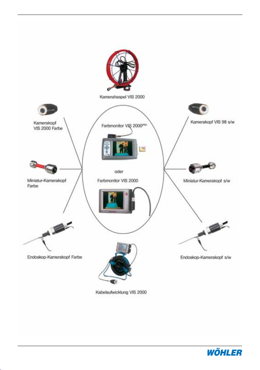
Abb. 2 zeigt die verschiedenen Komponenten im Überblick. Auf den nachfolgenden
Seiten werden diese inkl. des zusätzlich erhältlichen Zubehörs kurz beschrieben.
Page 8
8 Hotline: 0 29 53 / 73 211 Fax: 0 29 53 / 73 250
Kabelaufwicklung VIS 2000
6. Systemkomponenten
Abbildung 6.1: Systemkomponenten
Page 9

6. Systemkomponenten
6.1 Farbmonitor VIS 2000 (Best.-Nr. 7915 J)
Der Farbmonitor VIS 2000 ist ein kompakter, leichter Monitor, der in einer Ledertasche mit Blendschutz und Tragegurt
vor dem Körper getragen werden kann.
Im Menü werden Datum, Uhrzeit, ein
beweglicher Cursor sowie ein Titel mit
10 Zeichen eingeblendet.
Der Farbmonitor ist kompatibel zu folgenden Kameraköpfen:
-Miniatur-Kamerakopf Farbe
-Kamerakopf VIS 2000 Farbe
-Kamerakopf VIS 98 s/W
- Endoskop-Kamerakopf
-Miniatur-Kamerakopf s/w
6.2 Farbmonitor VIS 2000
PRO
(Best.-Nr. 6836 J)
Mit dem Farbmonitor VIS 2000
es jetzt möglich, einzelne Bilder, wie
auch Video-Sequenzen digital über den
integrierten Karten Slot auf eine CFSpeicherkarte aufzunehmen. Die gespeicherten Bilder (.jpg) und Videosequenzen
(.mov) können direkt vom Monitor über
die CF-Speicherkarte leicht auf einen PC
ausgelesen werden. Die integrierte Menüeinblendung stellt Längenanzeige, Darum
und Uhrzeit als auch einen Titel am großen
Farb-TFT-Display dar.
Der Farbmonitor ist kompatibel zu folgenden Kameraköpfen:
- Miniatur-Kamerakopf Farbe
- Kamerakopf VIS 2000 Farbe
- Kamerakopf VIS 98 s/W
- Endoskop-Kamerakopf
PRO
ist
Page 10
10 Hotline: 0 29 53 / 73 211 Fax: 0 29 53 / 73 250
Kabelaufwicklung VIS 2000
6. Systemkomponenten
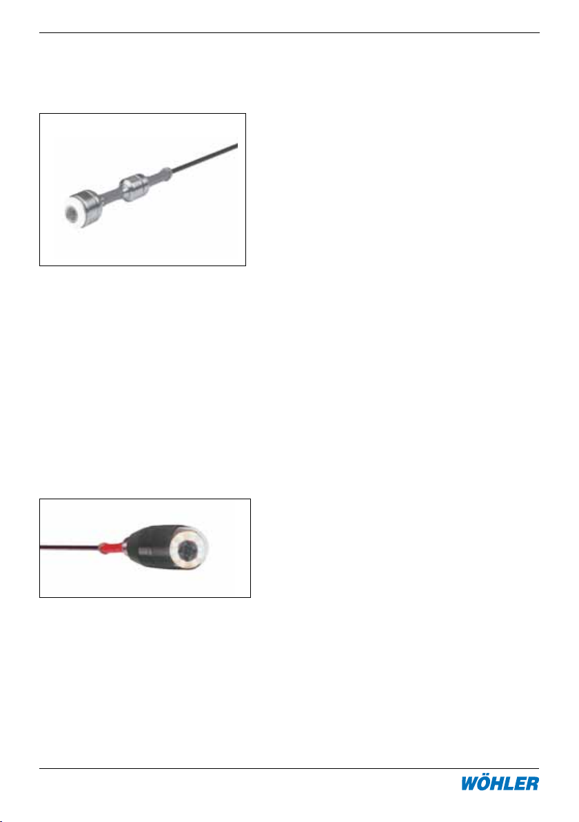
6.3 Miniatur Kamerakopf VIS 2000 Farbe (Best.-Nr. 7817 J)
Miniatur-Kamerakopf schwarz-weiß (Best.-Nr. 7871 J)
Der Miniatur Kamerakopf ist ein bis zu 3 bar
wasserdichter Kamerakopf im robusten Edelstahlgehäuse, der über ein Weitwinkelobjektiv
(f 2,5 mm) verfügt.
Aufgrund seines kleinen Durchmessers von nur
26 mm, der kurzen Baulänge und der robusten
flexiblen Stangenanbindung lässt sich der Miniatur Kamerakopf auch in engen Leitungen
durch mehrere Bögen hindurch problemlos
einsetzen.
Anwendung: Der Miniatur-Kamerakopf ist hervorragend geeignet zur optischen Inspektion
und Kontrolle von Kanälen, Rohren, Abgasleitungen, Lüftungsleitungen und Ringspalte mit
Durchmessern von ca. 40 mm bis 100 mm.
Speziell der Miniatur Kamerakopf s/w ist durch
seine außerordentliche Lichtempfindlichkeit
auch für die Kontrolle von Schornsteinen bis 20
x 20 cm und Abgasleitungen bis 30 cm Durchmesser geeignet.
6.4 Kamerakopf VIS 2000 Farbe (Best.-Nr. 7806 J)
Die Kameraköpfe VIS 2000 Farbe und VIS
98 s/w sind spritzwassergeschützt durch ein
vollständig gekapseltes Alugehäuse. Das Objektiv ist jeweils unter der Glaskuppel um 180°
schwenkbar und um 360° drehbar. Durch zuschaltbare helle Lichtkörper kann der Fernbereich ausgeleuchtet werden. Der Kamerakopf
ist mit einem Weitwinkelobjektiv (f = 2,0 mm)
ausgestattet.
Anwendung: Die Kameraköpfe sind hervorragend geeignet zur Dokumentation von Schäden und zur Kontrolle in Abgas- und Lüftungsanlagen sowie zur vorbereitenden Inspektion
bei Sanierungsarbeiten an Abgasanlagen ab
einem Durchmesser von ca. 70 mm.
Page 11
6. Systemkomponenten
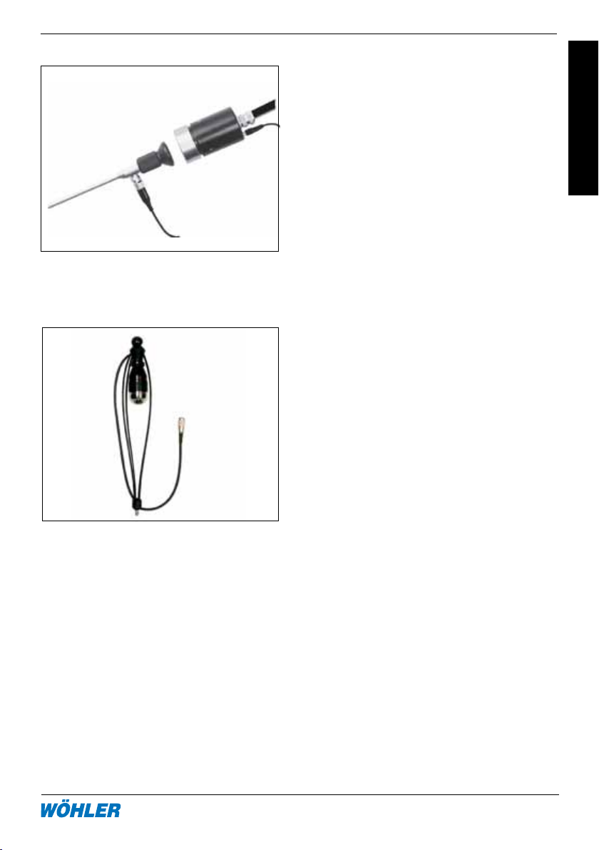
6.5 Endoskop Kamerakopf Farbe (Best.-Nr. 8697 J)
Der Endospop Kamerakopf Farbe wird vor
allem zur Dokumentation endoskopischer
Aufnahmen für die gutachterliche Tätigkeit eingesetzt. Außerdem ermöglicht er
die Visualisierung des Endoskopbildes für
mehrere Betrachter.
6.6 Video Inspektionssystem-Zubehör
Die Kamerahalterung ist mit einem
Verbindungskabel und einem Gewinde
M10 ausgestattet und kann so bequem
auf alle GFK-Stangen montiert werden.
Sie ist sowohl bei der vertikalen als
auch bei der horizontalen Inspektion
einsetzbar. Der Kamerakopf wird im
Schutzkorb mit Blickrichtung nach unten hinten positioniert, so dass einfallendes Tageslicht bei der Inspektion von
Schornsteinen nicht blendet.
Page 12

12 Hotline: 0 29 53 / 73 211 Fax: 0 29 53 / 73 250
Kabelaufwicklung VIS 2000
6. Systemkomponenten
6.6.2 Kamerafederführung (Best.-Nr. 8633 J)
Die Kamerafederführung erleichtert die Führung des Kamerakopfes am Kabel in vertikalen
Kanälen, indem sie das Verdrehen
und Pendeln des Kopfes verhindert. Die Feder ist auf die jewei-
6.6.3 Kamerahaspel (Best.-Nr. 7308 J, 7309 J, 7307 J)
Die Kamerahaspel wird mit Kamerastangen von 6 oder 7 mm lund
einer Länge bis zu 30 m angeboten.
Die Stange erlaubt die komfortable
Inspektion vertikal wie auch horizontal verlaufender Rohrsysteme.
6.6.4 Stabilisierungshülse mit Leinsternhalter (Best.-Nr. 3590 J)
Zur Stabilisierung der Kameraköpfe
VIS 2000 auf den Kamerastangen
beim Durchstoßen großer Leitungen;
einschraubbar in den Kamerakopf, die
Rollenführung oder die Kameraführung; Zur Führung beim Herabstoßen,
z.B. im Schonrstein, kann ein Leinstein
aufgesteckt werden (nicht im LIeferumfang enthalten)
Page 13
7. Zubehör
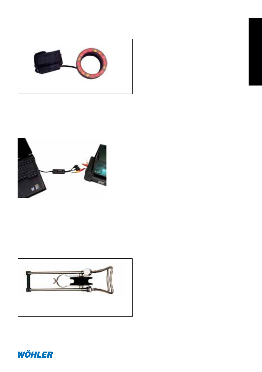
6.6.5 LED Zusatzbeleuchtung (Best.-Nr. 9377 P und 9177 P)
Die LED Zusatzbeleuchtung mit
rot-gelben und mit weißen LEDs zur
Arbeit mit den Kameraköpfen VIS 98
und 2000 ermöglicht die Ausleuchtung des Fernbereiches während der
Inspektion. Die Zusatzbeleuchtung
lässt sich einfach auf den Kamerakopf
6.6.6 Digitaler Bildwandler (Best.-Nr. 6233 J)
Mit Hilfe des digitalen Bildwandlers
können Bilder über eine USB-Schnittstelle auf ein Notebook oder einen PC
gespeichert werden.
7. Zubehör/Ersatzteile zur Kabelaufwicklung Vis 2000
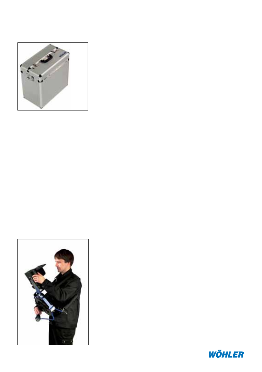
7.1 Teleskop-Rollbock (Best.-Nr. 5706 L)
Mit dem Teleskop-Rollbock lässt
sich der Kamerakopf am Kabel
kontrolliert herablassen. Da er aus
Edelstahl hergestellt ist, ist er besonders leicht und stabil. Er ist von
22 auf 40 cm ausziehbar.
Page 14
14 Hotline: 0 29 53 / 73 211 Fax: 0 29 53 / 73 250
Kabelaufwicklung VIS 2000
7. Zubehör
7.2 Transportkoffer XXL (Best.-Nr. 5824 L)
mit Schultergurt. Garantiert den
sicheren Transport der Kabelführung
samt Zubehör
7.3 Ersatzkabel
30 m Kamerakabel mit Metrierung Best.-Nr. 7812 L
20 m Kamerakabel mit Metrierung Best.-Nr. 9172 L
7.5 Verlängerungskabel (Best.-Nr. 8636 L)
10 m Verlängerungskabel mit Metrierung
7.4 Tragegurt (Best.-Nr. 8136 I)
Ermögicht es, die Kabelaufwicklung
bequem vor dem Körper zu tragen,
so dass beide Hände für die Arbeiten frei bleiben
Page 15

8. Konformitätserklärung
8. EG-Konformitätserklärung
Für das folgend bezeichnete Produkt
Videoinspektionsgerät VIS 2000
wird hiermit bestätigt, dass es den wesentlichen Schutzanforderungen entspricht,
die in den Richtlinien des Rates zur Angleichung der Rechtsvorschriften der Mitgliedstaaten über die elektomagnetische Verträglichkeit (2004/108/EG) festgelegt
sind.
Zur Beurteilung des Produkts hinsichtlich der elektromagnetischen Verträglichkeit
wurden folgende Normen herangezogen:
EN 55024 Störfestigkeit
EN 55022 Störaussendung
Dieser Erklärung wird verantwortlich für den Hersteller/Importeur
Adresse:
Schützenstr. 38, D-33181 Bad Wünnenberg
abgegeben durch:
Dipl.-Phys. Johannes Lötfering, Geschäftsführer
Bad Wünnenberg, 28.10.2004
Wöhler Messgeräte Kehrgeräte GmbH
9. Garantie und Service
9.1 Garantie
Jeder Farbmonitor VIS 2000 wird im Werk in allen Funktionen geprüft und verlässt
unser Werk erst nach einer ausführlichen Qualitätskontrolle.
Bei sachgemäßem Gebrauch beträgt die Garantiezeit auf den Monitor 12 Monate.
Ausgenommen sind Verschleißteile (wie z.B. Akkus/Batterien) und Verbrauchsmaterialien.
Die Kosten für den Transport und die Verpackung des Geräts im Reparaturfall
Page 16

16 Hotline: 0 29 53 / 73 211 Fax: 0 29 53 / 73 250
Kabelaufwicklung VIS 2000
9. Garantie und Service
werden von dieser Garantie nicht abgedeckt. Diese Garantie erlischt, wenn Reparaturen und Abänderungen von dritter, nicht autorisierter Stelle an dem Gerät
vorgenommen wurden.
Der SERVICE wird bei uns sehr groß geschrieben. Deshalb sind wir auch selbstverständlich nach der Garantiezeit für Sie da.
• EserfolgteinesofortigeReparatur,wennSiemitIhremGerätzuunsnach
Bad Wünnenberg kommen.
• SieschickendasGerätzuuns,wirreparierenesinnerhalbwenigerTage
und schicken es Ihnen mit unserem Paketdienst.
• SieerhaltengegeneinengeringenPauschalbetrageinLeihgerätgestellt.
• SofortigeHilfeerhaltenSiedurchunsereTechnikeramTelefon.
Page 17

9. Garantie und Service
Verkaufs- und Servicestellen
Deutschland
Wöhler Messgeräte Kehrgeräte
GmbH
Schützenstr. 41
33181 Bad Wünnenberg
Tel.: +49 2953 73-100
Fax: +49 2953 73-250
[email protected]
http://mgkg.woehler.de
Verkaufs- u. Servicestelle Süd
Wöhler Messgeräte Kehrgeräte
GmbH
Gneisenaustr.12
80992 München
Tel.: +49 89 1589223-0
Fax: +49 89 1589223-99
[email protected]
International
USA
Wohler USA Inc.
20 Locust Street, Suite 205
Danvers, MA 01923
Tel.: +1 978 750 9876
Fax.: +1 978 750 9799
www.wohlerusa.com
Verkaufs- u. Servicestelle Rhein/
Ruhr
Wöhler Messgeräte Kehrgeräte
GmbH
Castroper Str. 105
44791 Bochum
Tel.: +49 234 516993-0
Fax: +49 234 516993-99
[email protected]
Tschechien
Wöhler Bohemia s.r.o.
Za Naspern 1993
393 01 Pelhrimov
Tel.: +420 5653 49019
Fax: +420 5653 23078
[email protected]
Italien
Wöhler Italia srl
Corso Libertà 9
39100 Bolzano
Tel.: +390471402422
Fax: +39 0471
Page 18

Kabelaufwicklung VIS 20009. Garantie und Service
18 Hotline: 0 29 53 / 73 211 Fax: 0 29 53 / 73 250
Page 19
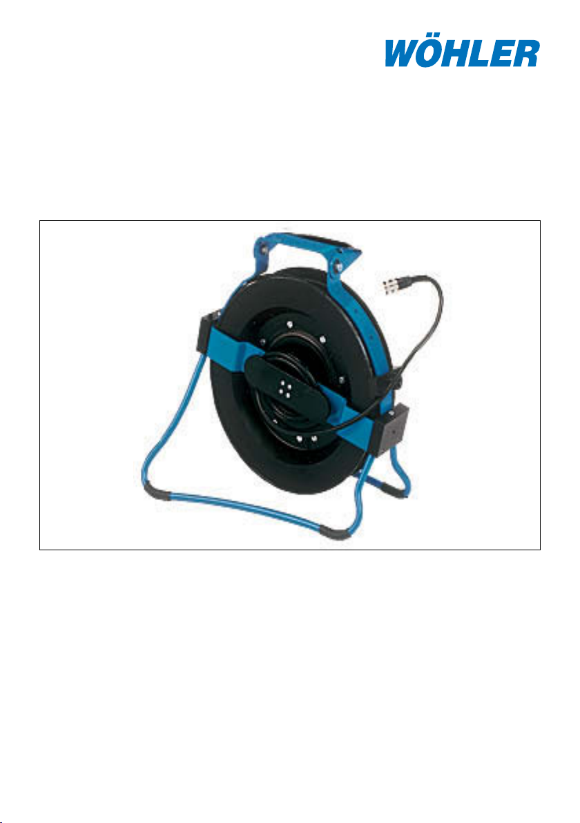
VIS 2000 Cable reel
with digital metric marking
Contents
1. Specification .............................19
2. Operation ................................... 20
3. Changing the cable ...................22
4. Maintenance .............................. 23
The Measure of Technology
5. System Components ................. 23
6. Accessories ............................... 29
7. Declaration of conformity .......... 30
8. Guarantee and Service .............. 31
Page 20

20 Hotline: 0 29 53 / 73 211 Fax: 0 29 53 / 73 250
Cable reel VIS 2000
1. Specification
1. Specification
The video inspection system is ideal for the optical control and examination of horizontally and vertically running exhaust systems (modern chimneys) as well as for
sewers and ventilation systems with a diameter from 6 to 30 cm. The compatible
system components offer various individual solutions which are perfectly convenient
for the corresponding job.
The cable reel described in this manual is used for the transport and the handling
of camera cables up to 30 m during the inspection. It comes with a support for the
monitor for more comfortable inspection and an integrated digital metric marking
for the measuring of the cable lenght, as well as a comfortable shoulder strap, a
cable brake and a collapsable stand. It is perfectly applicable for the inspection of
vertical pipings such as chimneys, downpipes and slots from above. By means of
the foldable monitor support and the collapsable stand of the winder, the set is very
compact and can comfortably be transported. At work, the unit may be carried in
front of the body by the 4-point-carrying-belt with the monitor in front of the body,
so that both hands will be free for the operation of the monitor and the cable with
the camera head. When the stand is completely unfolded, the cable reel can be
placed on a table or on the floor. An integrated cable brake holds the camera head
at the cable.
The integrated metric marking with a high resolution of 0.05 meters and a zerosetting button enables an exact determination of the position of the defect as well
as the measurement of distances in the duct.
1.2 Tecnical Data
Size, unfolded:
Height: 34 cm
Width: 35 cm
Depth: 10 cm
Weight: 2.5 kg (without cable)
Max. cable length 30 m
Integrated metric marking:
Functional principle: digital
Resolution: 0.05 m
Measuring range: 0 - 30.00 m
Operation button: Reset to zero, Input of parameters
Standby: LED
Page 21
2. Operation
2. Operation
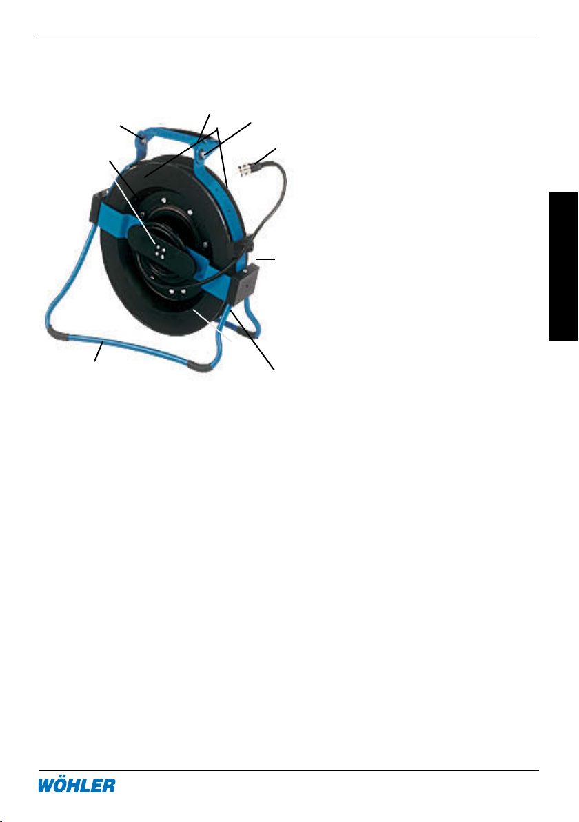
2.1 Controls
4
5
9
1
3
Figure 2.1 Foto Foto
ändern
2.2 Operation of the device
7
10
1 Operation button
(Reset to zero during the mea-
8
surment, input of parameters
during the installation of the
new cable )
2 Cable reel
3 Stand
4 Collapsible monitor holder
6
5 Grip
6 Brake (back side)
7 Connection for 4-point-belt
8 Cable connection to the moni-
tor
2
9 Attachment of the monitor
connection cable (Middle of
9
the back side)
10 Adjusting button for changing
the position of the monitor
support
2.2.1 Connection of the camera heads
All camera-heads are connected via a clutch socket with 8 poles to the cable in
the cable reel (cable jack with 8 poles).
Plug camera head and camera cable together and then turn the thread
clockwise for closing the screw connection tightly.
2.2.2 Connection of the monitors
First, unfold the monitor support while pressing the adjusting button. (Figure
2.1, part 10). Now screw the monitor out of the monitor support. After that
connect the cable connection of the cable reel (figure 2.1, part 8) to the video
in-socket of the monitor.
Page 22
22 Hotline: 0 29 53 / 73 211 Fax: 0 29 53 / 73 250
Cable reel VIS 2000
2. Operation
2.2.3 Inspection of vertical pipings
Pipings, such as chimneys or downpipes, can be inspected best from above.
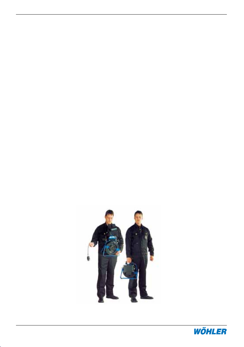
The cable reel is ideal for that purpose. If you carry it in front of the body with the
four-point carrying belt system, your hands will be free for working. First jam the
two narrow snap-hooks in the two openings at the left and the right under the
grip. The two round snap-hooks will be fixed to the stand, so that the red resetbutton on the reel shows to the body. This way you can move optimally and you
are able to regard the display at every time.
If it is not necesarry to change the position of the cable reel during the inspection,
it will be best to put the cable reel on a table or on the floor while working. In this
case you will have to unfold the stand.
After having put the cable reel in the best position, release the brake by turning the
knob at the reel half a rotation left. Now you can let the cable with the camera head
down in the pipe. If you want to control a special point of the pipe in a more detailed
way, you will have to fix the brake by turning the rotation button back.
During transport the brake generally has to be fixed and the stand and the monitor
holder must be folded.
Page 23

2. Operation
2.3 Digital Metric Marking
The cable reel has a digital metric marking integrated, so that the position of
the defect can be exactly determined during the inspection and a distance
measurement in the pipe will be possible. The green LED shows that the metric
marking is ready for operation. The LED will shine as soon as the camera head is
switched on. The result of the meter measurement will be shown in the monitor. If
necessary, you will have to configurate the display menu correspondingly.
A special button can reset the metric marking to zero in every position, for
example at the chimney entry. The way of the camera until the entry of the
chimney will not be included in the measurement and the exact position of the
defect in the pipe will be shown. For measuring the distance, reset the metric
marking to zero at the initial point (by pressing the operation button for two
seconds) and then read off the distance at the end point.
3. Changing the cable
For changing the cable, first release the brake. Then pull the cable carefully out
of the reel. Now disconnect the connection between cable and cable reel and
take out the cable.
Then carefully turn the cable reel clockwise almost one rotation back up to the
stop position. Guide the jack of the new cable through the loop to the clutch
socket and connect them. Now you can roll up the viper anticlockwise. While
rolling up the cable, pay attention that it coils smooth around the reel.
Fix the brake as described in point 2.2.3.
If you insert a cable with another length, you will have to change the parameters. Press the operation button during about three seconds for switching on the
monitor. The parameters will be shown in the first line. With a double-click on the
operating button of the cable reel the blinking cursor can be moved to the right.
Clicking once the counter can be changed. By pressing the button for three seconds, the value will be stored. After that the new parameters will be displayed.
The parameters must be entered according to the following table:
Page 24

24 Hotline: 0 29 53 / 73 211 Fax: 0 29 53 / 73 250
Cable reel VIS 2000
4. Maintenance
Type lenth running meters external dimension internal dim.
Cable winder 20m 695 24 19
Cable winder 30m 1042 27 19
Camera viper 42 20m 382 42
38
Camera viper 42 30m 573 42
36
Camera viper 36 20m 561 36
4.Maintenance
The cable can be cleaned by pulling it through a damp cloth. Clean the cable reel
with a damp cloth only, but never with water and cleaning agent. Pay attention that
no water will enter the metric marking.
Attention: Before opening the device disconnect it from any voltage
source. (e.g. monitor unit.) Only an authorized establishment should
5. System Components
The video-inspection-system VIS 2000 offers a great number of compatible components to adapt the device to varios special tasks, that components are.
· monitor and control unit
· camera head
· connection cable/rod
· accessories
This way it is possible to combine the perfect equipment for each task. You can
also complete the system later on for new tasks.
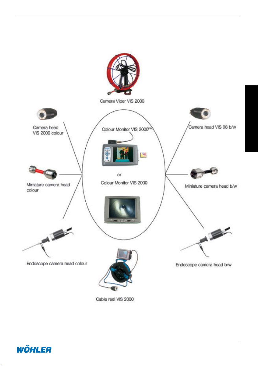
Figure 5w.1 shows the different components. On the next pages, the components
and their accessories are shortly described.
Page 25
5. System Components
5. System Components
Figure 5.1: System Components
Page 26
26 Hotline: 0 29 53 / 73 211 Fax: 0 29 53 / 73 250
Cable reel VIS 2000
5. System Components
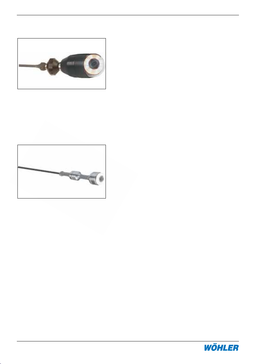
5.1 Camera head VIS 2000 Colour (Order no. 7806 J )
Camera head VIS 98 b/w (Order no. 7801)
The camera heads VIS 2000 colour and VIS
98 b/w are splashproof enclosed in an aluminium housing. They enable a simple and
exact inspection by the 180o tilt and 360o pan
function of the camera head. Extra LEDs for
additional light make it possible to see even
at far distances. The camera head comes
with a wide angle objective (f=2.0 mm).
Applications: Inspection and documentation of damage in ventilation and exhaust
systems from aprox. 70 mm.
5.2 Miniature camera head (Order no. 7817 J)
Miniature camera head b/w (Order no. 7871 J )
The mini camera head is watertight up to 3
bar and has a durable stainless steel housing
with a wide angle objective (f=2.0 mm).
Because of the small diameter of only 26
mm, the short length and the flexible viper
it can be used in small lines and pipes with
various bows without problems.
Applications: Inspection and direct documentation of flue lines and ventilations as
well as water pipes with a diameter from 40
mm to 100 mm.
Especially the mini camera head black and
white is extremely sensitive to light and
therefore convenient for the control of chimneys up to 20 x 20 cm and flue lines up to
30 cm Ø.
Page 27
5. System Components
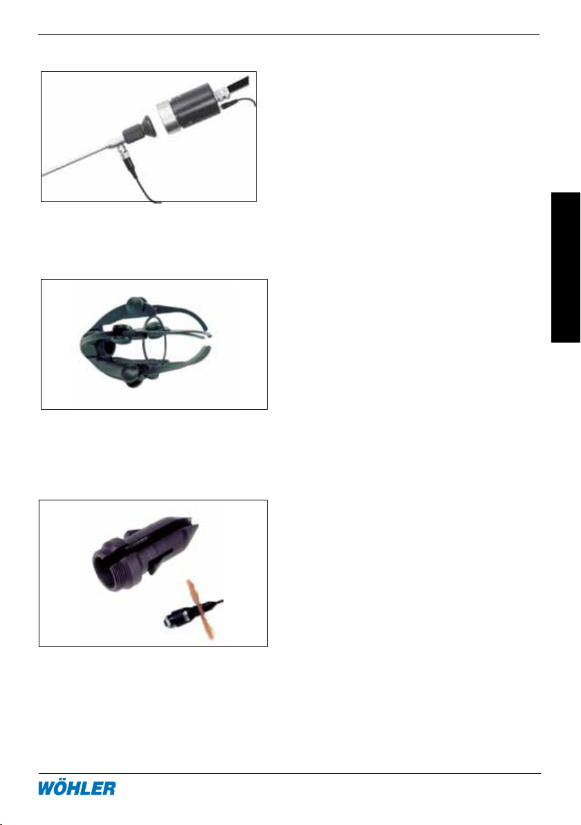
5.3 Endoscope camera head colour (Order no. 8697 J )
The Endoscope Camera Head color is used
especially for the documentation of endoscopic snapshots for expertises. It also makes it
possible that various persons can regard the
endoscopic picturenon a monitor.
5.4 Assessories Video inspection
5.4.1 Camera roller guide (Order no. 7826 J)
Camera roller guide for the Camera head VIS
2000 and VIS 98, for pushing the camera
head in horizontally running exhaust systems
and ventilation systems and chimneys.
Advantages/Features:
• guidance rolls
• simple installation at the camera head
• special steel protection, powder coated
5.4.2 Stabilization sleeve with star holder (Order no. 3590 J)
For the stabilization of the camera heads VIS
2000 and VIS 98 on the camera viper when
pushing through large pipes; it is simply
screwed into the roller guide. When pushing
downwards, for example in the chimney, a
star can be plugged on for better guiding
(not included in delivery).
Page 28

28 Hotline: 0 29 53 / 73 211 Fax: 0 29 53 / 73 250
Cable reel VIS 2000
5. System Components
5.4.3 Telescope Dolly (Order no. 5706 L)
For letting down the camera head at the
cable. Especially light and stable because
of special steel. Extendable from 22 to 40
cm.
5.4.4 LED supplementary light (Order no. 9377 P und 9177 P)
The LED supplementary light with red-yellow
and white LEDs, for camera head VIS 2000
and VIS 98 makes it possible to iluminate the
distant zone during the inspection.
5.4.5 Camera viper (Order no. 7822 J )
The camera viper is available with a camera
rod of 6 or 7mm diameter and a length of
20.05 m. With the viper a comfortable inspection of horizontally and vertically running
exhaust systems is possible.
Page 29
5. System components
5.4.6 Viper Camera Holder (Order no. 8680 J)
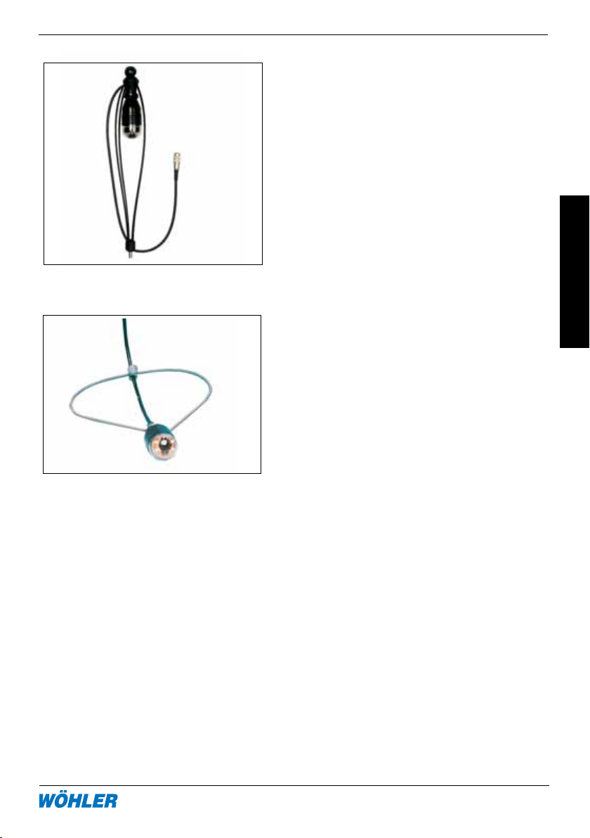
The camera holder provides a connection
cable and a M 10 thread and therefore can
easily be connected to our cleaning rods.
The camera is in a protective cage and faces
down, so that incidental daylight does not
cause problems. Attached to rods both, horizontal and vertical pipes can be examined.
5.4.7 Camera Spring Guide (Order no. 8633 J)
For centering of the camera head in vertical
vents. A stainless steel spring prevents a
rotating and oscillating of the camera head.
The spring is adjustable to the tubing size.
5.4.8 Special Cable (Order no. 9181 L)
0.8 m, for the connection of the Camera rod to the monitor.
5.4.9 Camera rod
Camera rod black, flexible, 6 mm Ø, 5 m long (Order no. 7821 J)
Camera rod black, flexible, 6 mm Ø, 20 m long (Order no. 7818 J)
Camera rod black, flexible, 6 mm Ø, 30 m long (Order no. 7819 J)
Camera rod red, stable, 7 mm Ø, 5 m long (Order no. 7305 J)
Camera rod red, stable, 7 mm Ø, 20 m long (Order no. 7829 J)
Camera rod red, stable, 7 mm Ø, 30 m long (Order no. 7306 J)
Page 30
30 Hotline: 0 29 53 / 73 211 Fax: 0 29 53 / 73 250
Cable reel VIS 2000
6. Accessories
6. Accessories/Spare Parts of the Colour Monitor VIS 2000
6.1 Power Supply VIS 2000
PRO
(Order no. 6837 J)
for mains operation and charging
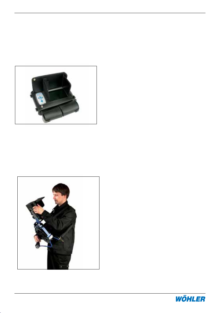
6.2 Leather protection bag for monitor VIS 2000
With glare protection and shoulder-strap. For
the secure transport and a comfortable position of the monitor during the inspection.
6.3 Adaptercable (Order no. 8637 O)
for the 12 volt car-system
6.4 Shoulder strap (Order no. 8136 I)
Makes it possible to carry the Cable reel
comfortably in front of the body, so that both
hands will be free for working.
PRO
(Order no. 6838 J)
Page 31

7. Declaration of conformity
7. Declaration of conformity
Manufacturer: WÖHLER Messgeräte Kehrgeräte GmbH
Schützenstr. 41, 33181 Bad Wünnenberg
declares that the following product:
Product name: Wöhler VIS 2000 Cable reel
complies with key safety requirements set down in the guidelines of the Council
for the Harmonisation of the Legal Requirements of the Member States in relation
to electromagnetic compatibility (2004/108/CE).
The following standards are used to assess the product in terms of electromagnetic
compatibility:
EN 55024 Resistance to jamming
EN 55022 Emitted interference
This declaration is issued on behalf of the aforementioned manufacturer by:
Johannes Lötfering, Managing Director Bad Wünnenberg, 28.10.2004
Page 32

32 Hotline: 0 29 53 / 73 211 Fax: 0 29 53 / 73 250
Cable reel VIS 2000
8. Guarantee and Service
8. Guarantee and Service
8.1 Guarantee
Every Wöhler VIS 2000 cable reel has been subjected to a thorough functional
check and only leaves our factory after detailed quality control. The final inspection
is recorded in detail in a test report and is kept by us on our premises. If the device
is used correctly, the guarantee period is 12 months from the date of purchase.
This guarantee does not cover wear and tear parts.
The guarantee does not include the costs for transport and packing material in case
of repair. It will expire, if third persons, who are not authorized, repaire or change
the device.
We see SERVICE as a very important element in our business. That is why we are
still available to you even after the guarantee period has expired.
• AnimmediaterepairwillbecarriedoutifyoubringyourmetertousinBad
Wünnenberg.
• Ifyousendusthemeter,itwillbereturnedtoyoubyourdeliveryservice
after repair in just a few days.
• Wecanlendyouadeviceforasmallstandardfee.
• Youcanobtainimmediatehelpfromourengineersbytelephone
Page 33

Sales and service sites
Points of sale and service
Germany
Wöhler Messgeräte Kehrgeräte
GmbH
Schützenstr. 41
33181 Bad Wünnenberg
Tel.: +49 2953 73-100
Fax: +49 2953 73-250
[email protected]
http://mgkg.woehler.de
Verkaufs- u. Servicestelle Süd
Wöhle r Mes s g e r äte Kehrg e r ä t e
GmbH
Gneisenaustr.12
80992 München
Tel.: +49 89 1589223-0
Fax: +49 89 1589223-99
[email protected]
International
USA
Wohler USA Inc.
20 Locust Street, Suite 205
Danvers, MA 01923
Tel.: +1 978 750 9876
Fax.: +1 978 750 9799
www.wohlerusa.com
Verkaufs- u. Servicestelle Rhein/
Ruhr
Wöhler Messgeräte Kehrgeräte
GmbH
Castroper Str. 105
44791 Bochum
Tel.: +49 234 516993-0
Fax: +49 234 516993-99
[email protected]
Czech Republic
Wöhler Bohemia s.r.o.
Za Naspern 1993
393 01 Pelhrimov
Tel.: +420 5653 49019
Fax: +420 5653 23078
[email protected]
Italy
Wöhler Italia srl
Corso Libertà 9
39100 Bolzano
Tel.: +390471402422
Fax: +39 0471
Your contact:
Page 34

Page 35
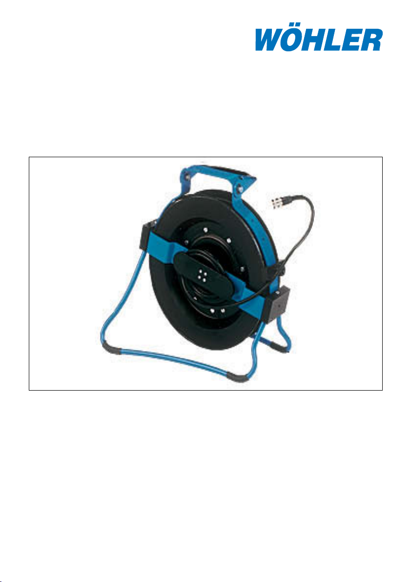
Avvolgicavo VIS 2000
con contametri digitale incorporato
Indice
1. Specificazione .............................36
2. Uso .............................................. 37
3. Sostituzione del cavo ..................39
4. Guide per l’ispezione ................... 40
Soluzioni tecniche su misura
5. Indicazioni sulla manutenzione
e la cura ....................................... 41
6. Componenti del sistema ............. 41
7. Certificato di conformità .............. 47
8. Garanzia: .....................................47
Page 36

Avvolgicavo VIS 2000
36 Tel: 0471 402422 Fax: 0471 406099
1. Specification
1. Specificazione
Il sistema di videoispezione VIS 2000 permette il controllo visivo e la documentazione di tubi e canali, come ad es. impianti di scarico, impianti di ventilazione,
tubi acqua di rifiuto ecc. La vasta gamma di componenti di sistema, compatibili
l’uno con l’altro, offre una scelta individuale per la composizione della telecamera
perfettamente adattabile al rispettivo compito da svolgere.
L’avvolgicavo VIS 2000 qui descritto serve per il trasporto comodo e per una maneggevolezza confortevole del cavo dotato di telecamera, la cui lunghezza massima
è di 30 m, durante l ’ispezione. L’avvolgicavo offre inoltre un supporto regolabile
per il trasporto e per l’ispezione per collocarvi l’unità del monitor e di comando, un
contametri digitale integrato per misurare la lunghezza del cavo, una cintura confortevole a 4 punti, un freno del cavo nonché un piede pieghevole. Si presta molto
bene all’impiego dall’alto per l’ispezione di tubi verticali, come per canne fumarie
o per pluviali, pozzi ecc.. Con l’unità motore ribaltata verso il basso, compreso il
contenitore della testata della telecamera e con il piede ribaltato si crea un’unità di
videoispezione compatta e completa, che, usando la maniglia o la cintura, si può
trasportare comodamente sul luogo d’impiego. Grazie alla cintura a 4 punti sul luogo
è possibile trasportare l’unità davanti al proprio corpo con il monitor tratto fuori,
di modo che entrambe le mani rimangano libere per l’uso del monitor e del cavo /
della testata di telecamera. Per l’uso sul tavolo o sul pavimento si può ribaltare il
piede pieghevole, in modo da ottenere una stabilità sicura. Un freno integrato del
cavo serve ad assicurare la testata della telecamera sul cavo.
Il contametri integrato di un’elevata risoluzione di 0,05 metri è dotato di un tasto di
azzeramento che permette di individuare in modo preciso la posizione del danno
permettendo inoltre misurazioni di distanza all’interno del tubo.
1.2 Dati tecnici
Dimensioni nello stato ripiegato:
Altezza: 34 cm
Larghezza: 35 cm
Profondità: 10 cm
Peso: 2,5 kg (senza cavo)
Lunghezza max. cavo: 30 m
Contametri integrato:
Funzionamento digitale
Risoluzione: 0,05 m
Campo di misura: 0 - 30,00 m
Tasto di comando: azzeramento, inserimento parametri
Indicazione dispositivo pronto: LED
Page 37
2. Uso
2. Uso
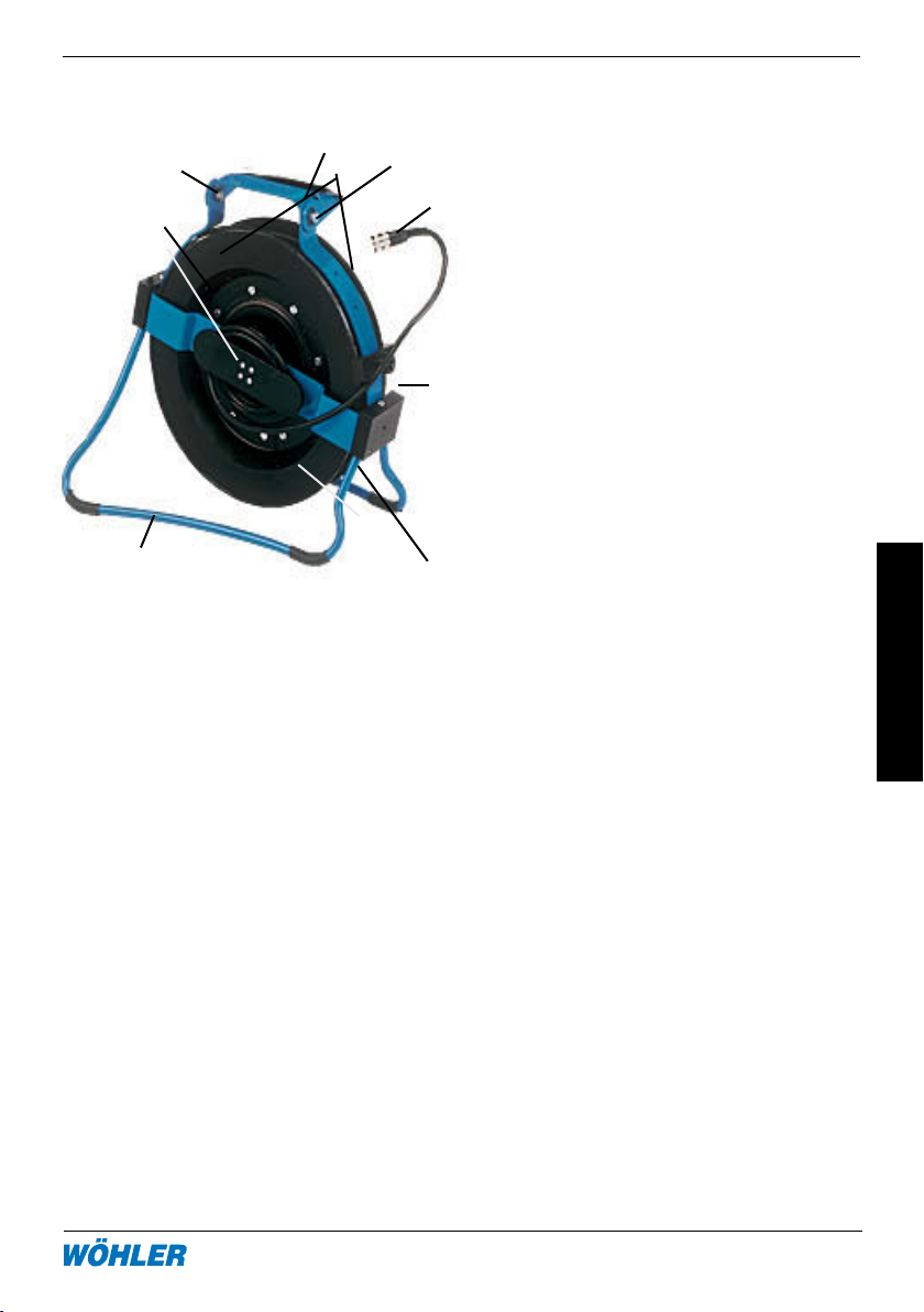
2.1 Elementi di comando
5
9
1
3
Figura 2.1 Foto Foto
ändern
2.2 Manovra di unità
4
7
10
1 Tasto di comando
8
(azzeramento durante la
misurazione, impostazione pa-
rametri per l’inserimento di un
nuovo cavo)
2 Tamburo per cavi
3 Piede ribaltabile
6
4 Supporto monitor con possibili
tà di ribaltamento
5 Maniglia
6 Freno (sul retro)
7 Possibilità di collegamento
2
Cintura a 4 punti
8 Collegamento cavo al monitor
9
9 Fissaggio del cavo di collega
mento monitor (retro centrale)
10 Pulsante di impostazione per
modificare la posizione del
supporto monitor
2.2.1 Collegamento dei testata
Scegliere l’avvolgicavo con il cavo rigido adatto per robustezza, raggio di curvatura e lunghezza
Montare la testata adatta, scegliendo tra la minitestata colori o b/n a seconda
delle esigenze (b/n vede meglio nelle canne fumarie).
2.2.2 Collegamento dei monitor
Per collegare il monitor, ribaltare innanzitutto il supporto del monitor verso l’alto
(fig. 1, parte 4). Per farlo premere il pulsante d’impostazione (fig. 1, parte 10). Poi
collegare il supporto monitor con la presa d’ingresso del piede del monitor.
In seguito collegare la connessione dell’avvolgicavo (fig. 1, parte 8) con la presa
d’ingresso sul monitor.
Page 38
Avvolgicavo VIS 2000
38 Tel: 0471 402422 Fax: 0471 406099
2. Uso
2.2.3 Ispezione di tubazioni verticali
Il modo migliore di ispezionare tubazioni verticali, come ad es. canne fumarie o tubi
verticali a gravità, è di farlo dall’alto, ad es. dal tetto. L’aspo infatti è perfettamente
idoneo a questo proposito. Per avere libere entrambe le mani, durante l’ispezione
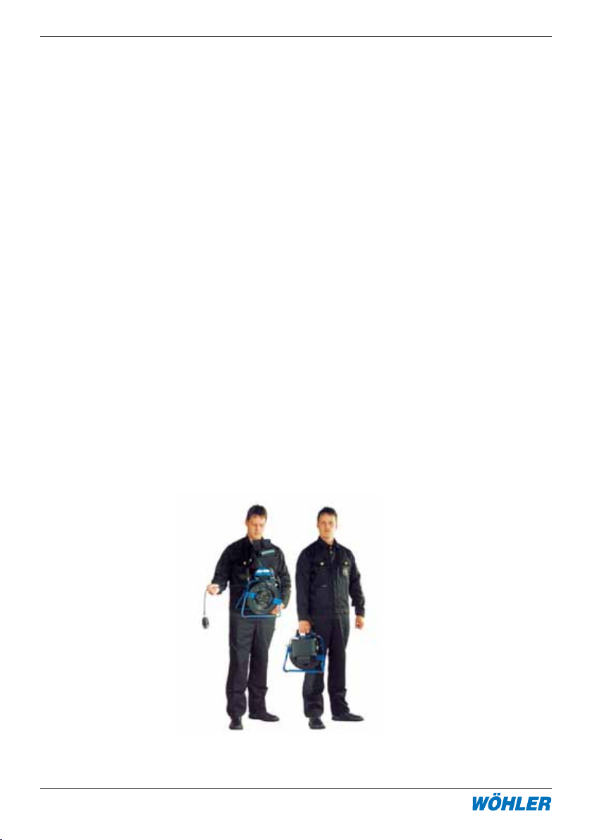
stessa si può portare l’aspo davanti al proprio corpo, fissando la cintura a 4 punti
sugli appositi punti dell’aspo. Fissare i due moschettoni stretti negli appositi alloggiamenti posizionati a sinistra ed a destra al di sotto della maniglia. I due moschettoni
tondi vanno fissati sul piede ribaltabile in modo tale che il tasto rosso di reset venga
portato sul tamburo verso il proprio corpo. Poi mettere le cinture sopra le proprie
spalle, di modo che il componente in plastica sia situato sulla propria schiena. In
tal modo con l’apparecchiatura si ha una libertà ottimale di movimento e si può
vedere comodamente in qualsiasi momento il display anche con la protezione
antiriflessi compresa.
Se non è necessario cambiare la posizione dell’aspo e dell’operatore durante
l’ispezione, è opportuno appoggiare per l’ispezione l’aspo su un tavolo oppure sul
pavimento. Per farlo, ribaltare il piede all’infuori.
Dopo aver posto l’avvolgicavo nella posizione idonea per il compito da svolgere,
sbloccare il freno del tamburo effettuando metà giro con la manopola nera. Per
sbloccare il freno girare la manopola verso la sinistra. Ora si può introdurre nel
tubo verso il basso il cavo insieme alla testata della telecamera. Se si desidera
ispezionare in modo più preciso un determinato punto del tubo, bloccare di nuovo
il freno girando di nuovo indietro la manopola.
Durante il trasporto, in via di principio il freno del tamburo va sempre bloccato. Il
piede ribaltabile ed il supporto del monitor vanno ribaltati verso l’interno.
Page 39

3. Sostituzione del cavo
2.3 Contametri digitale
Nell’aspo è incorporato un contametri digitale, in modo da poter determinare
con precisione durante l’ispezione la posizione del danno e per consentire inoltre
una misurazione precisa delle distanze all’interno del tubo. Un LED verde indica
che il contametri è pronto al funzionamento, il LED si illumina non appena la
testata della telecamera è stata inserita. Il risultato del contametri si può leggere
sul monitor. In caso necessario, a questo proposito occorrerà appositamente
configurare il menù dello schermo del monitor.
Il tasto di comando consente di azzerare il contametri in qualsiasi posizione,
come ad es. all’ingresso della canna fumaria. Così il percorso del cavo fino
all’ingresso della canna fumaria non viene integrato nel conteggio, e verrà
indicata la posizione precisa del danno. Per misurare le distanze, azzerare il
metraggio al punto di partenza (tenendo premuto il tasto sull’aspo per 2 sec.
circa) e poi al punto finale leggere comodamente la distanza.
3. Sostituzione del cavo
Per sostituire il cavo occorre innanzitutto sbloccare il freno. In seguito estrarre con
cura il cavo fino alla fine. Sconnettere poi la connessione tra cavo e guida del cavo
e estrarre il cavo.
In seguito girare con cura l’aspo in senso orario per poco meno di un giro fino alla
battuta. Fare passare il connettore del nuovo cavo alla presa attraverso l’asola e
collegarlo con la spina dell’aspo. Ora è possibile avvolgere il cavo verso la sinistra.
Nell’inserire il cavo occorre fare attenzione che esso si avvolga in modo equo lungo
la larghezza del tamburo del cavo.
Bloccare il freno del tamburo come descritto al punto 2.2.3.
In caso che sia stato impiegato un cavo di una lunghezza diversa, occorrerà pro-
grammare nuovamente i parametri. A questo proposito tener premuto il tasto di
comando dell’aspo per 3 secondi circa e accendere il monitor. In alto compare una
riga contenente i parametri. Con un doppio clic sul tasto di comando dell’aspo il
cursore lampeggiante si sposta verso la destra, un unico clic permette invece di
modificare il contatore. Per salvare i valori usare un clic di una durata di 3 sec.. In
seguito verranno visualizzati i parametri attuali. I parametri vanno impostati secondo
la tabella di seguito riportata:
Page 40

Avvolgicavo VIS 2000
40 Tel: 0471 402422 Fax: 0471 406099
4. Guide per l‘ispezione
Tipo Lunghezza Impulsi Da Di
Avvolgicavo 20m 695 24 19
Avvolgicavo 30m 1042 27 19
Aspo 42 20m 382 42 38
Aspo 42 30m 573 42 36
Aspo 36 20m 561 36 32
Aspo 36 30m 868 36 30
4. Guide per l’ispezione
In seguito vengono riportati alcuni consigli generali relativi all’impiego di guide durante l’ispezione di tubi e canali che risultano dall’esperienza da noi fatta. Siccome
ogni sistema di tubi e di canali è individualmente diverso, naturalmente per ogni
singolo caso occorrerà decidere sul luogo sull’uso delle guide. Nel scegliere la guida
più idonea occorre osservare che essa, oltre a guidare bene il cavo, deve garantire
che si possa inserire ed estrarre la testata della telecamera senza problemi. Occorre
tener conto del rischio che la guida rimanga incastrata all’interno del tubo.
Ispezione di tubi Ø 40 - 50 mm Impiegare sempre il sistema di videois-
pezione senza accessori.
Ispezione di tubi Ø 50 -70 mm Impiegare sempre il sistema di vide-
oispezione senza accessori.
Usare il manicotto di spinta esclusiva-
mente nella parte orizzontale, quando
è presente acqua oppure fango.
Ispezione di tubi Ø 70 - 100 mm E’ possibile effettuare l’ispezione senza
problemi sia con che senza il manicotto
di spinta. Per tubi verticali a gravità o
per l’ispezione verticale occorre usare
un peso di guida.
Ispezione di tubi Ø 100 - 125 mm E’ possibile usare una stella di cen-
traggio e/o un manicotto di spinta con
protezione dell’obiettivo.
Ispezione di tubi a partire da Ø 154 Vedasi sopra, però la testata della tele-
camera va spinta solo per pochi metri.
Page 41

5. Indicazioni sulla manutenzione e la cura
5. Indicazioni sulla manutenzione e la cura
Per rimuovere lo sporco dal cavo fare passare il cavo attraverso una pezza umida.
Pulire anche l’avvolgicavo con una pezza umida e, se necessario, con un detergente
dolce. Occorre assolutamente fare attenzione che non ci sia acqua che penetri nella
zona del contametri.
Attenzione: prima di aprire l’apparecchiatura staccarla da qualsiasi fonte di tensione
(unità monitor ecc.). In qualsiasi caso i lavori sull’avvolgicavo vanno effettuati solo
da una società qualificata e autorizzata dalla Wöhler.
6. Componenti del sistema
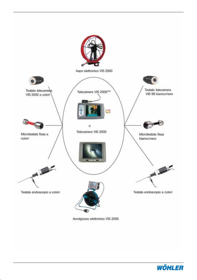
Il sistema di videoispezione VIS 2000 dispone di una vasta gamma di accessori e
componenti per adattarsi ad ogni esigenza dell’impianto. Ogni sistema di videoispezione si compone dei 4 componenti base:
· unità monitor per colori e b/n
· testata telecamera colori o b/n
· cavo/cavoasta di collegamento
· accessori
Page 42
Avvolgicavo VIS 2000
42 Tel: 0471 402422 Fax: 0471 406099
6. Componenti del sistema
Fig. 6.1: Componenti
Page 43
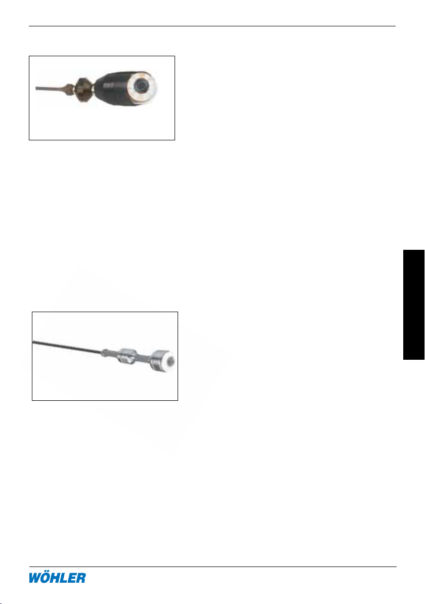
6. Componenti del sistema
6.1 Testata telecamera rotativa
6.2 Microtestata fissa
La testata telecamera rotativa permette la
videoispezione a “mezzaluna”, perché girevole a 360° e ruotabile a 180°. La testata è
protetta da una cupola in vetro con protezione IP 64 contro gli spruzzi d’acqua.
L’obiettivo a gran d’angolo (f=2,0mm) della
telecamera è protetto contro i riflessi di
luce da un anello e molla a trascinamento.
La testata rotativa è particolarmente adatta
per la videoispezione di canne fumarie, canali di ventilazione e canali asciutti o umidi
tutti i tipi a partire da un diametro minimo
di 70 mm.
Esistono due versioni:
VIS 2000 testata a colori, mostra bene i
particolari colorati cod. 7806
VIS 98 testata bianco/nero, indicata particolarmente per le canne fumarie molto
scure cod. 7801.
La microtestata fissa è a tenuta d’acqua fino
3 bar, realizzata in corpo d’alluminio e dispone di un obiettivo a gran d’angolo (f=2,5mm).
Grazie al diametro ridotto di soli 2,6mm, la
lunghezza contenuta e al raccordo flessibile
è possibile utilizzare la microtestata anche
nei canali piccoli a partire da ca. 40 mm (con
max. 3 curve) fino a max. 100 mm.
La microtestata b/n è particolarmente luminosa e indicata per le videoispezione di
canne fumarie fino le misure 200x200mm o
diametro 300mm.
Esistono due versioni:
Microtestata colori per canali e c.f.
7817
Microtestata b/n per canne fumarie
7871
Page 44
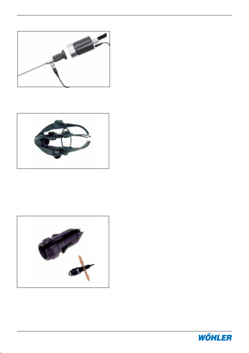
Avvolgicavo VIS 2000
44 Tel: 0471 402422 Fax: 0471 406099
6. Componenti del sistema
6.3 Testata endoscopio
6.4 Accessori vari per videoispezione
Guida a rotelle, protegge la testata sia per
le videoispezione dall’alto con il cavo o la
sondacavo, o nei canali con spinta attraverso
la sondacavo. La guida a rotelle è completa
di raccordo a baionetta per il fissaggio della
testata, filetto per il montaggio dello stabilizzatore con centratore.
Per il montaggio togliere il cestello superiore
svitandolo in senso antiorario, inserire la testata fissandola con il raccordo a baionetta
e rimontare il cestello. Collegare il cavo o
sondacavo.
Guida a rotelle cod. 7826
Permette di collegare ogni endoscopio
Wöhler direttamente alla VIS 2000PRO,
permettendo la memorizzazione delle immagini riprese con l’endoscopio flessibile o
il tecnoendoscopio rigido.
Testata endoscopio cod. 8697
Stabilizzatore con centratore, con filetto per
testata o guida a rotelle, con fissaggio rapido
delle spazzole con foro 28 mm, rende rigido
l’attacco della sondacavo alla testata o guida
a rotelle, per l’inserimento nei canali, nonché
protegge la cupola dai maggiori urti laterali
nella videoispezione anche di canne fumarie,
nonché permette di montare una spazzola
centratrice.
Stabilizzatore con centratore cod.
3590
Page 45
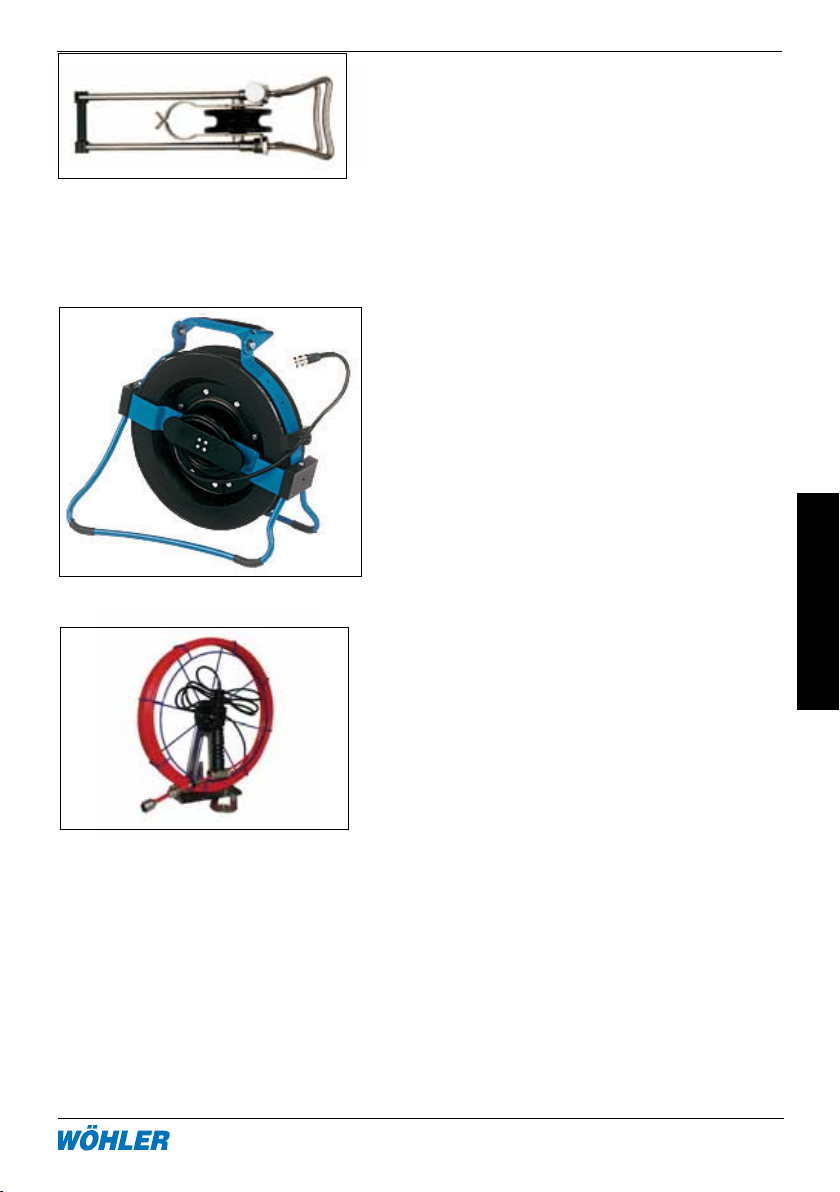
6. Componenti del sistema
taccato dal bordo del comignolo o della
portina d’ispezione del sottotetto.
Inserire la carrucola con il doppio ferretto a V
rivolto verso l’operatore e la doppia asta regolabile va appoggiata sulla parete opposta.
Regolare la lunghezza, inserire la testata e
far scorrere il cavo sulla rotella.
Carrucola regolabile cod. 5706
Avvolgicavo elettronico con contametri digitale e vite di fissaggio per VIS 2000PRO,
completo di piedini, freno e cavo collegamento unità monitor. Il cavo metrato invece
non viene fornito, perché compreso nella
telecamera. L’avvolgicavo è adatto per ricevere fino a 30 m di cavo.
L’avvolgicavo elettronico trasmette i metri
sullo schermo della telecamera e disopone
dell’interruttore d’azzeramento.
Avvolgicavo elettronico cod. 3816
Aspo elettronico con contametri digitale,
piede incorporato, gancio per cintura, cavo
di collegamento all’unità monitor, adatto
per testata ruotabile e microtestata. L’aspo
è fornito con sondacavo da 6 o 7mm e
permette di spingere le diverse testate sia
dal basso verso l’alto (videoispezione di
secondari di ccr), che dall’alto verso il basso
(canne fumarie), nonché in orizzontale (canali
e tubazioni).
• asponero6mmx5m 7821
• asponero6mmx20m 7818
• asponero6mmx30m 7819
• asporosso7mmx5m 7305
• asporosso7mmx20m7829
• asporosso7mmx30m7306
Page 46
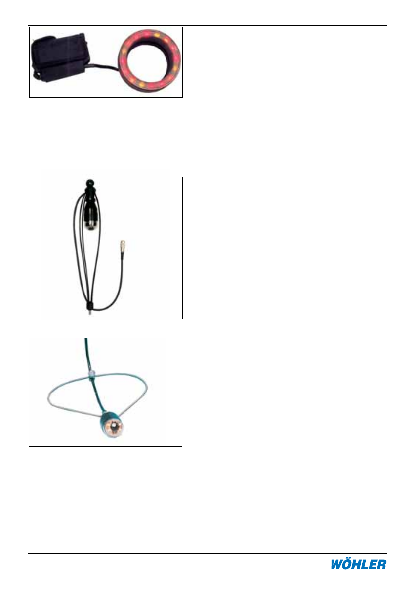
Avvolgicavo VIS 2000
46 Tel: 0471 402422 Fax: 0471 406099
6. Componenti del sistema
Luci supplementari con led bianchi o giallorossi, da applicare direttamente sulla testata
telecamera e con pacco 4 pile mignon in
custodia da fissare sul cavo. Le luci supplementari aumentano la luce nelle canne
fumarie particolarmente grandi (oltre 20 mm)
oppure con le pareti completamente nere dalla
fuliggine o dal catrame.
Luci bianche per testata colori e b/n
9377
Luci colorate per testata b/n 9177
Guida 180°, protegge la testata ruotabile e
permette la spinta mediante miniaspo 42,
aspo e maxiaspo. Permette la videoispezione dal basso o di canali con vista verso
l’operatore in modo da non sporcare o rompere la testata telecamera. Completo di cavo
collegamento al cavo metrato e filetto M10 per
la sonda dell’aspo. In testa è dotata di filetto
M10 femmina per applicare una spazzola
terminale come centratore.
Guida 180° cod. 8680
Guida a molla per inserire la testata ruotabile
al centro della canna fumaria, composto
dall’anello di fissaggio e una molla con vite di
fissaggio. Inserire l’anello nel filetto testata o
della guida a rotelle e fissare la molla a dovuta
distanza direttamente sul cavo metrato.
Guida a molla cod. 8633
Custodia in similpelle per l’unità monitor (compresa nella fornitura dell’unità monitor) adatta
per il montaggio delle custodie delle testate,
come riportato nella foto accanto
Page 47

7. Componenti del sistema
7. Certificato di conformità
Il Avvolgicavo VIS 2000 è conforme le disposizioni legislative italiane ed in particolare
è impiegabile per le videoispezione di canne fumarie come richiesto dalle norme UNI
10845 e UNI 1443. Il Avvolgicavo VIS 2000 è inoltre adatta per la videoispezione
nei canali di ventilazione e con le microtestate anche per la videoispezione delle
tubazioni dell’acqua, dello scarico ecc.
Il certificato conformità decade immediatamente se lo strumento viene
aperto da persone o ditte non espressamente autorizzate dalla ditta Wöhler.
Dichiarazione conformità CE:
Il prodotto denominato VIS2000 è conforme alle norme europee per la compatibilità elettromagnetica (2004/108/CE). Per la verifica sono state utilizzate le seguenti
norme:
• EN55024
• EN55022
Sul prodotto viene riportato il marchio CE e la seguente dichiarazione di conformità
è firmata dall’amministratore delegato sig. Lötfering Johannes del produttore Wöhler
MGKG GmbH – Germania – Bad Wünnenberg.
La dichiarazione conformità CE decade immediatamente se lo strumento viene
aperto da persone o ditte non espressamente autorizzate dalla ditta Wöhler.
8. Garanzia:
Ogni Avvolgicavo VIS 2000 viene controllata in tutte le sue funzioni e lascia la fabbrica solo dopo accurato controllo qualità. El aspo telecamera è coperta da garanzia
12 mesi sui difetti di fabbricazione, salvo manomissioni da parte di persone non
autorizzate o di rotture dovute all’errato uso, difforme dalle istruzioni. Sono esclusi
dalla garanzia i pezzi d’usura come le batterie, le cupole ecc.. I costi per il trasporto
e l’imballo dello strumento in caso di necessità d’intervento è a carico del cliente.
La garanzia decade immediatamente se lo strumento viene aperto da persone
o ditte non espressamente autorizzate dalla ditta Wöhler.
Per assicurare lunga vita al suo prodotto consigliamo una verifica periodica con
pulizia e taratura dello strumento. Consigliamo concordare un appuntamento ogni
12-24 mesi direttamente con il SAT, il quale offre il servizio di ritiro a domicilio.
Page 48

8. Servizio di assistenza programmata
Avvolgicavo VIS 2000
Servizio di assistenza programmata
Per assicurare lunga vita al suo prodotto consigliamo una verifica periodica con
pulizia e taratura dello strumento. Consigliamo concordare un appuntamento ogni
12-24 mesi direttamente con il SAT, il quale offre il servizio di ritiro a domicilio.
Points of sale and service
Germany
Wöhler Messgeräte Kehrgeräte
GmbH
Schützenstr. 41
33181 Bad Wünnenberg
Tel.: +49 2953 73-100
Fax: +49 2953 73-250
[email protected]
http://mgkg.woehler.de
Verkaufs- u. Servicestelle Süd
Wöhle r Mes s g e r äte Kehrg e r ä t e
GmbH
Gneisenaustr.12
80992 München
Tel.: +49 89 1589223-0
Fax: +49 89 1589223-99
[email protected]
Verkaufs- u. Servicestelle Rhein/
Ruhr
Wöhler Messgeräte Kehrgeräte
GmbH
Castroper Str. 105
44791 Bochum
Tel.: +49 234 516993-0
Fax: +49 234 516993-99
[email protected]
International
USA
Wohler USA Inc.
20 Locust Street, Suite 205
Danvers, MA 01923
Tel.: +1 978 750 9876
Fax.: +1 978 750 9799
www.wohlerusa.com
Italy
Wöhler Italia srl
Corso Libertà 9
39100 Bolzano
Tel.: +390471402422
Fax: +39 0471
Czech Republic
Wöhler Bohemia s.r.o.
Za Naspern 1993
393 01 Pelhrimov
Tel.: +420 5653 49019
Fax: +420 5653 23078
[email protected]
Your contact:
48 Tel: 0471 402422 Fax: 0471 406099
 Loading...