

Page 1

The measure of technology
US
Operating manual
Service Camera
Wöhler VIS 200 / 250
Wöhler VIS 300 / 350
Order no. 23102 2014-02-10
Page 2

Contents
2
Contents
1 General Information .............................. 4
1.1 Information about the operating instructions . 4
1.2 Notes ............................................................. 4
1.3 Proper use ..................................................... 5
1.4 Scope of supply ............................................. 5
1.5 Transporting .................................................. 6
1.6 Information on disposal ................................. 6
1.7 Manufacturer's address ................................. 6
2 Important information........................... 7
3 Camera Models ..................................... 9
4 Technical data ..................................... 10
4.1 Monitor ........................................................ 10
4.2 Miniature Camera Head (Wöhler VIS
200/250) ...................................................... 10
4.3 Miniature Camera Head (Wöhler VIS
300/350) ...................................................... 11
4.4 Push rod ...................................................... 12
4.5 Electronic distance counter ......................... 12
4.6 Memory (Wöhler VIS 250 / 350) ................. 12
6 Design and function ........................... 13
6.1 Video inspection system .............................. 13
6.2 Control panel ............................................... 15
6.3 Monitor ........................................................ 18
6.3.1 Adjusting the Color ...................................... 18
6.3.2 Transition from 16:9 Screen to 4:3 Screen .. 19
7 Getting started .................................... 20
7.1 Rechargeable battery status and recharging 20
7.2 Working position .......................................... 21
8 Working with the camera ................... 22
8.1 Switching on the system and monitor .......... 22
8.2 Memory (Wöhler VIS 250 / 350) .................. 23
8.3 Inspection .................................................... 26
8.4 Information displayed on the monitor .......... 26
Page 3

Contents
3
US
8.4.1 Displaying the position of the camera head
(Wöhler VIS 250/350) .................................. 26
8.5 Home Function (only Wöhler VIS 350) ........ 27
8.6 Video Record (Wöhler VIS 250 / 350) .......... 28
8.7 Video playback (Wöhler VIS 250 / 350) ....... 28
9 Images (Wöhler VIS 250 / 350) ........... 29
10 Delete a Video (Wöhler VIS 250 / 350) ..
.............................................................. 29
11 Transferring images and videos to a
PC (Wöhler VIS 250/350) .................... 30
12 Video Playback at PC
(Wöhler VIS 250/350) ........................... 31
12.1 Installing the VLC viewer ............................. 31
12.2 Generating snapshots .................................. 31
12.3 Output directory for snapshots ..................... 32
13 Guide accessories .............................. 33
14 Faults ................................................... 34
15 Maintenance ........................................ 35
15.1 Regular maintenance ................................... 35
15.2 Changing the dome of the Camera Head
Wöhler VIS 300/350 ..................................... 35
15.3 Camera head ............................................... 35
15.4 Push rod ...................................................... 35
15.5 Monitor ......................................................... 35
16 Accessories......................................... 36
17 Warranty Wohler VIS Service Camera ..
.............................................................. 37
Points of sale and service ............................ 40
Page 4
General Information
4
1 General Information
1.1 Information about the
operating instructions
Read these operating instructions carefully. They
will enable you to operate the Wöhler VIS 200/250
and VIS 300/350 safely. Keep this manual for your
information
This manual refers to different camera models.
Therefore it may include instructions which do not
apply to your camera. Those explanations which
do not mention one or more camera models explicitly, refer to all four models.
The Wöhler VIS 200/250 and Wöhler VIS 300/350
should be used by trained professionals for its
intended use only.
Liability is voided for any damages caused by not
following this manual.
1.2 Notes
WARNING!
Not following this warning can cause injury or
death.
ATTENTION!
Not following this note can cause permanent
damage to the camera.
NOTE!
Useful information
Page 5

General Information
5
1.3 Proper use
The Camera is designed to visually inspect and
document the condition of pipes and shafts, for
example in flue gas systems, ventilation systems
as well as for inspecting underground pipes etc.
The device is designed to be used by trained professionals only.
Any other use is considered improper use.
1.4 Scope of supply
Device
Scope of supply
Wöhler VIS 200 / 250
Wöhler VIS 300 / 350
Case
Push rod
Monitor
1 anti-slide-mat
NiMH battery
mini USB cable
(Wöhler VIS 250 /
350)
Wöhler
VIS 200/250/300
1 rechargeable battery 12 V NiMH
Wöhler VIS 350
2 rechargeable batteries 12 V NiMH
Wöhler VIS 200 / 250
Miniature Camera
Head Color
Wöhler VIS 300 / 350
Pan & tilt color camera head
5 replacement plastic
domes
Wöhler VIS 250 / 350
SD card 2 GB
Page 6
General Information
6
1.5 Transporting
To avoid damage occurring during transport it is
imperative that the instrument is transported in the
original case designed for the purpose.
1.6 Information on disposal
Do not dispose of electronic equipment in domestic waste. Dispose of electronic equipment in accordance with applicable environmental regulations.
You may hand in any defective batteries taken out
of the unit to our company as well as to recycling
places of public disposal systems or to selling
points of new batteries or storage batteries.
1.7 Manufacturer's address
Wöhler Messgeräte Kehrgeräte GmbH
Schützenstr. 41
33181 Bad Wünnenberg
Tel.: +49 2953 73-100
Fax: +49 2953 73-96100
Email: [email protected]
Page 7

Important information
7
2 Important information
Eye protection
WARNING!
Never point a connected camera head at your own
or somebody else's eyes when the camera is
switched on. The LEDs are extremely bright and
can cause eye damage.
WARNING!
Guide the rod with due care and attention. As the
rod is made of flexible material, it can make whipping movements if it slips. Protect your eyes in
particular.
Working environment
WARNING!
Only place the camera on firm level ground and
ensure a secure position of camera and user, especially when working in high altitude, e.g. when
working on the roof.
WARNING!
Make sure that the parts that you are going to inspect are no live parts.
CAUTION!
Protect the camera head against oil and acid.
Never use the camera head and rod to push obstructions.
Operating temperature
CAUTION!
Do not use the camera in temperatures above
40°C. High temperatures can damage the camera.
Page 8

Important information
8
Resistance to water
CAUTION!
Only the camera head and the rod are waterproof.
Keep the camera system dry and away from water!
Resistance to impacts
CAUTION!
The camera system is not impact resistant. Do not
throw or allow the case to fall!
Accessories
CAUTION!
Use only original Wöhler accessories and spare
parts!
Strong magnetic or electric
fields
NOTE!
Do not use the camera near television towers,
mobile radio equipment or other sources of magnetic or electric fields, as these may impair the
quality of the displayed image.
Extraneous influences
NOTE!
Extraneous influences such as static discharges
can cause the device to malfunction. If a malfunction occurs, switch the monitor off and on again.
Page 9

Camera Models
9
3 Camera Models
Different camera models Wöhler VIS can be acquired. The difference between the models described in this version are as follows:
VIS 350
VIS 300
VIS 250
VIS 200
Camera head
Ø 1 ½ "
pan & tilt
Ø 1 ½ "
pan & tilt
Ø 1 "
Ø 1½ "
integrated
transmitter
1
2
1
2
Position indicator
Electronic meter
counter
Record video
Menu
Home function
Control panel
7 keys with
shift
5 keys
7 keys
1 key
Application
Flue gas lines Ø 2,4" and
larger with 87° bends (and
smaller)
Waste water lines of Ø 2,8"
and larger
Chimneys
Ventilation lines of Ø 2,4"
and larger
Analyse damage in Waste
water pipes of Ø 2,8 " and
larger
Flue gas lines Ø 2 ½ " and
larger
Ventilation lines of Ø 2 ½ "
and larger
Analyse damage in Waste
water pipes of Ø 2 ½ " up
to Ø 4.9”
1
The transmitter can be switched on and off in the menu, see chapter 8.2
2
When the camera is switched on, the transmitter will be permanently active.
Page 10
Technical data
10
4 Technical data
4.1 Monitor
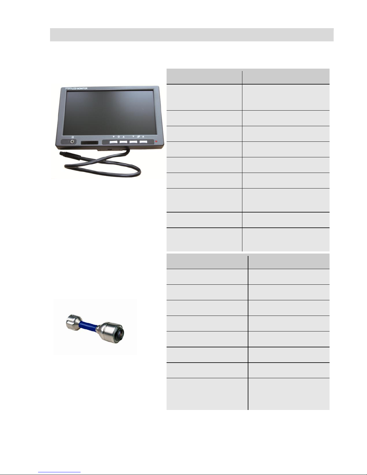
Fig. 1: Monitor
Description
Details
TFT display
7"/ 16:9 and 4:3 format
(Default 16:9)
Weight
14 oz
Dimensions housing
6,9 x 4,5 x 1,3 "
Video output
FBAS signal
Power supply
via camera system
Voltage
12 V
Operating
temperature
-4 ... 122 °F
Storage temperature
32 ... 104 °F
Connection cable to
the camera system
79"
4.2 Miniature Camera Head
(Wöhler
VIS 200/250)
Fig. 2: Miniature Camera Head
Description
Details
Type:
1/3" COLOR CMOS
Light sensitivity
12V, Lux sec
Lens:
f = 0.09", F = 0.10"
Viewing angle:
120°
Light source:
12 white LEDs
Degree of protection:
Waterproof to IP 68
Dimensions
Ø 1" x 1 1/2 "
Frequency of the
transmitter integrated
in the camera head
8.9 kHz
Page 11
Technical data
11
4.3 Miniature Camera Head
(Wöhler
VIS 300/350)
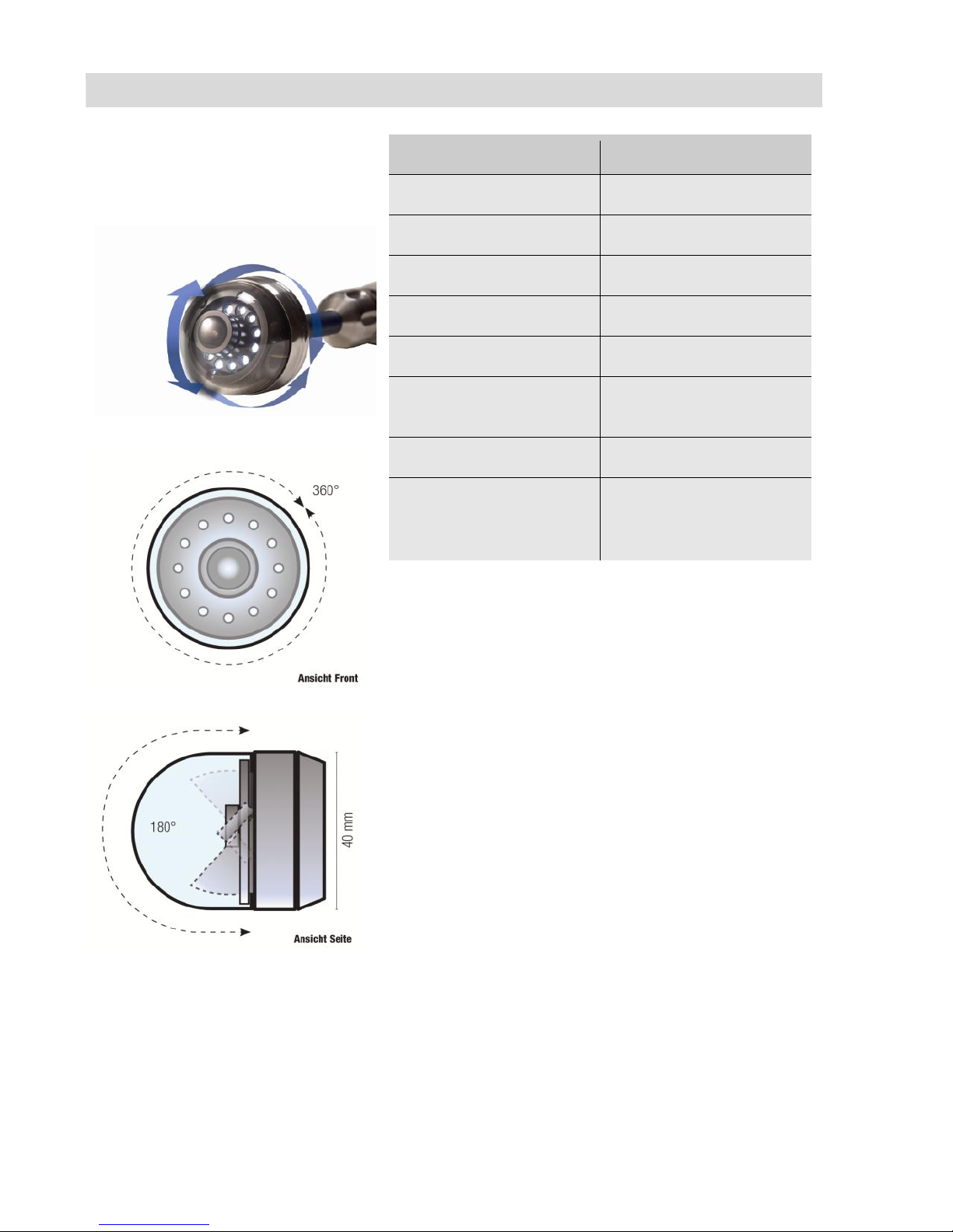
Fig. 3: Camera Head pan & tilt
Fig. 4: Pan the camera head 360°
Fig. 5: Tilt the camera head 180°
Description
Details
Type:
1/3" COLOR CMOS
Light sensitivity
12 V, Lux sec
Lens:
f = 0.09", F = 0.10"
Viewing angle:
120°
Light source:
12 white LEDs
Degree of protection:
Waterproof to IP 67
Dimensions
Ø 1 ½ " x 2.4 mm
Frequency of the
transmitter integrated
in the camera head
8.9 kHz
Page 12

12
4.4 Push rod
Description
Details
Length:
787"
optional
1181"
Diameter
0.3 mm (VIS 3xx)
0.2 mm (VIS 2xx)
4.5 Electronic distance
counter
Description
Details
Resolution:
1.5"
Maximum Deviation
10 % of reading
4.6 Memory
(Wöhler VIS 250 / 350)
Description
Details
Memory card
32 GB max. (If you are
using a memory card
other than the one
included in the scope
of supply, you must
format it first (FAT32)
before you can use it
on a PC.)
Capacity
ca. 1h / GB
Resolution of the video
640 x 480 (VGA)/
max. 30 fps
Video format
ASF (MPEG4)
Page 13
Design and function
13
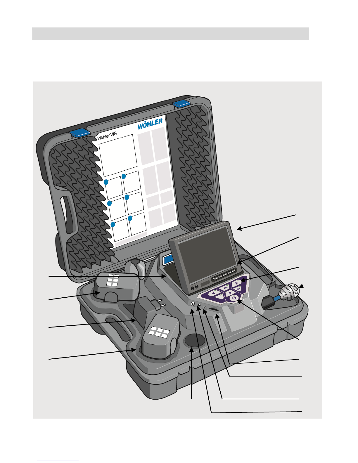
6 Design and function
6.1 Video inspection system
Fig. 6: Case (Wöhler VIS 350)
1
2 3 4
5
6 7 8
10
9
11
12
13
14
Page 14

Design and function
14
Legend
1
Monitor
2
Monitor controls
- Brightness / contrast
- Color
3
Camera control
with record and play - function (Wöhler VIS 250 / VIS 350)
home function aligns the camera head to a straight position and menu for the
monitor settings (Wöhler VIS 350)
4
camera head, waterproof:
Wöhler VIS 300 / VIS 350: pan and tilt color camera head 40 mm Ø
Wöhler VIS 200 / 250 Miniature color camera head Ø 26 mm
5
Main power switch with the following functions:
- ON /OFF (system)
- Reset distance measurement
- Escape
- Delete (when SHIFT mode is activate)
6
Cardslot for memory card (Wöhler VIS 250 / 350)
7
Mini-USB-port (Wöhler VIS 250 / 350)
8
Power supply socket (18V/1,6A)
9
Video out
10
Accessory compartment 1
11
Rechargeable battery, extra (only Wöhler VIS 350)
12
Power supply
13
Rechargeable battery, in use
14
Accessory compartment 2
Page 15
Design and function
15
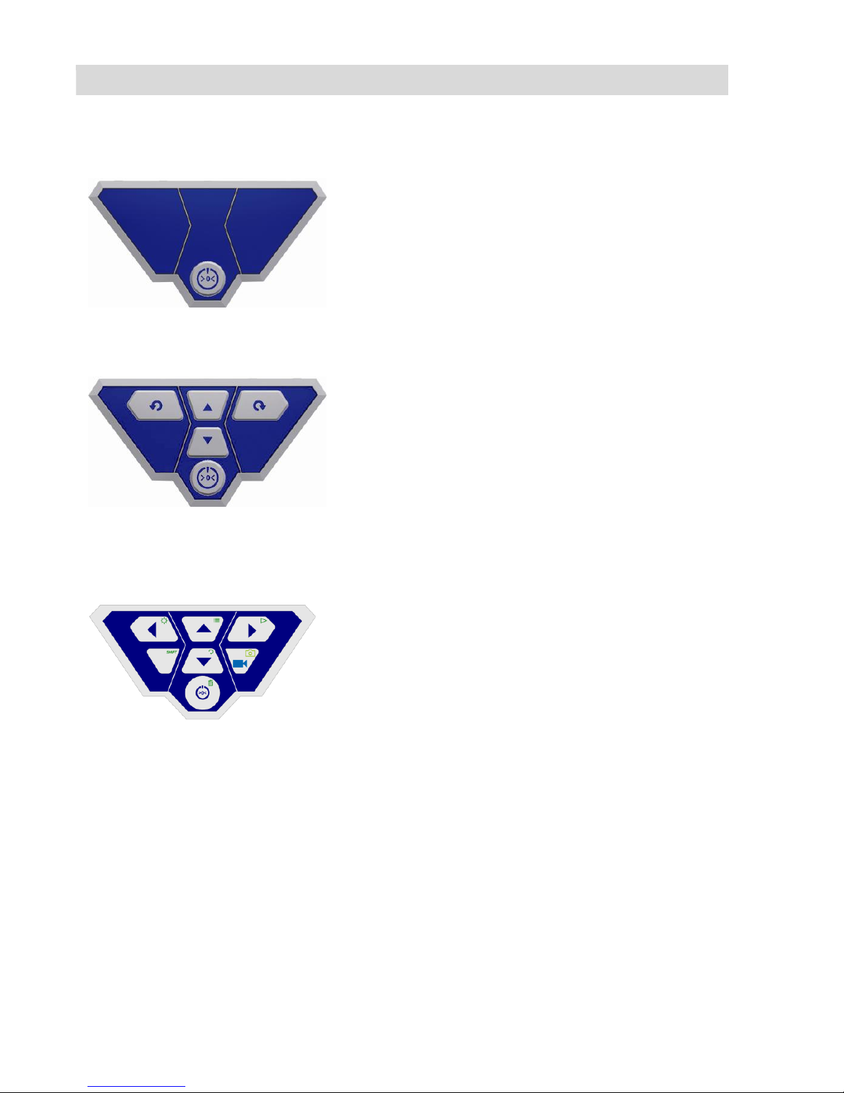
6.2 Control panel
VIS 200
Fig. 7: Control Panel
Wöhler VIS 200
Control Panel Wöhler VIS 200 with ON/OFF-key
VIS 300
Fig. 8: Control Panel
Wöhler VIS 300
Control Panel Wöhler VIS 300 with ON/OFF-key
and control keys for the pan and tilt camera head
Wöhler VIS 250 / 350
Fig. 9: Control Panel
Wöhler VIS 250 / 350
Control Panel
Wöhler VIS 250 / 350
Page 16
Design and function
16
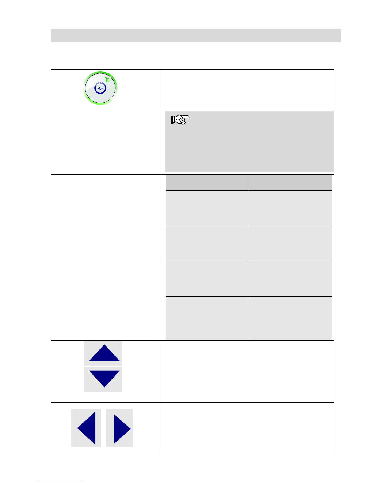
The keys on the control panel have the following functions:
Wöhler VIS 200/250/300/350
ON/OFF key turns the whole camera system
on/off (monitor and camera head).
NOTE!
The ON/OFF key is framed by a green light
when the system is switched on and the battery
is charged.
The lower half of the light framing the ON/OFF
key flashes red during the recharging process.
Functions
The ON/OFF key
Press
Function
When the system is
switched off:
Briefly
Switch system on
When the system is
switched on:
Hold 2 seconds
Switch system off
When the system is
switched on:
Briefly
Reset distance counter
When the system is
switched on:
(Wöhler VIS 250 /
350)
Escape
Exit menu
Camera head operating keys
(Wöhler VIS 300/350)
Tilt the camera head 180°
Camera head operating keys
(Wöhler VIS 300/350)
Rotate the camera head 360°
Page 17
Design and function
17
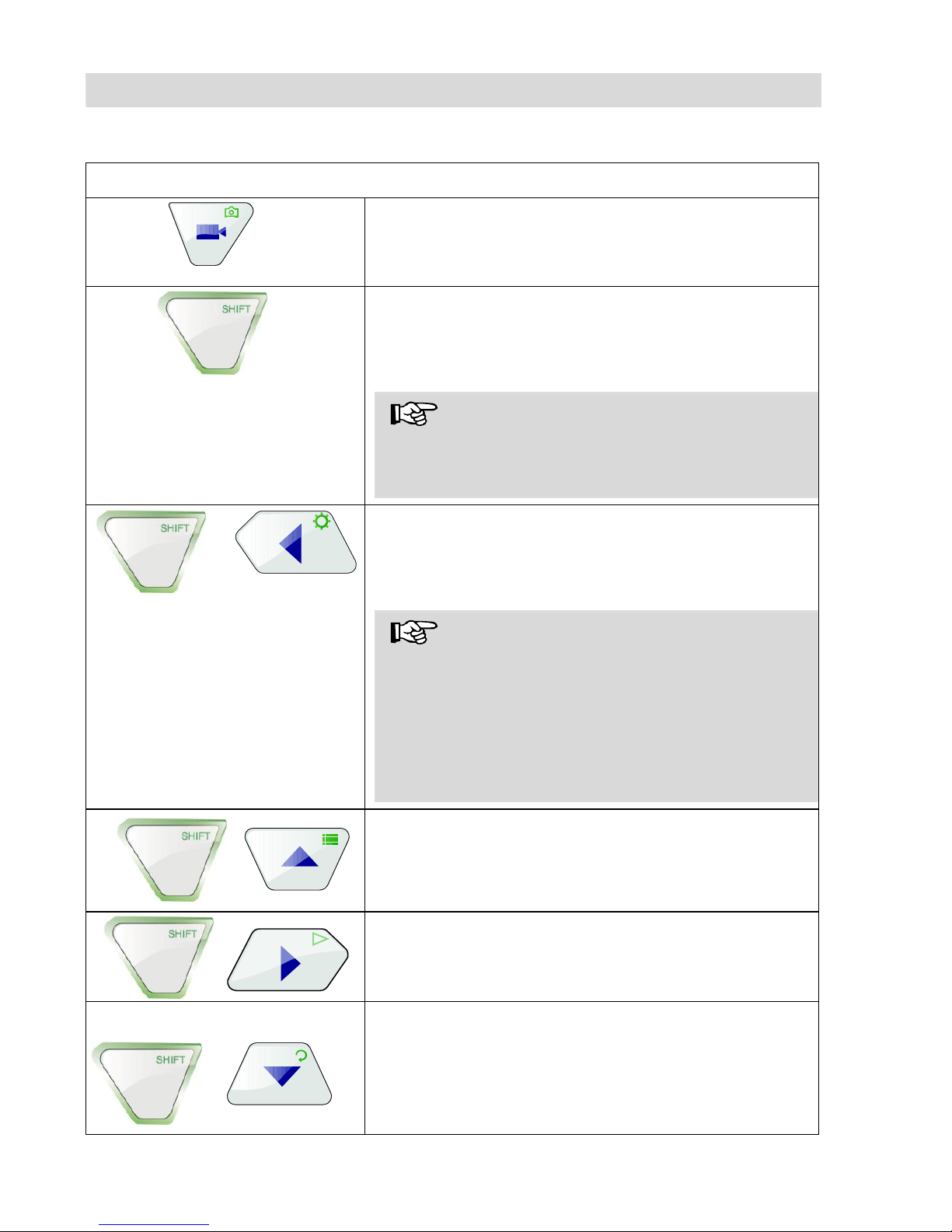
Wöhler VIS 250 / 350
VIDEO key
Start/stop recording video
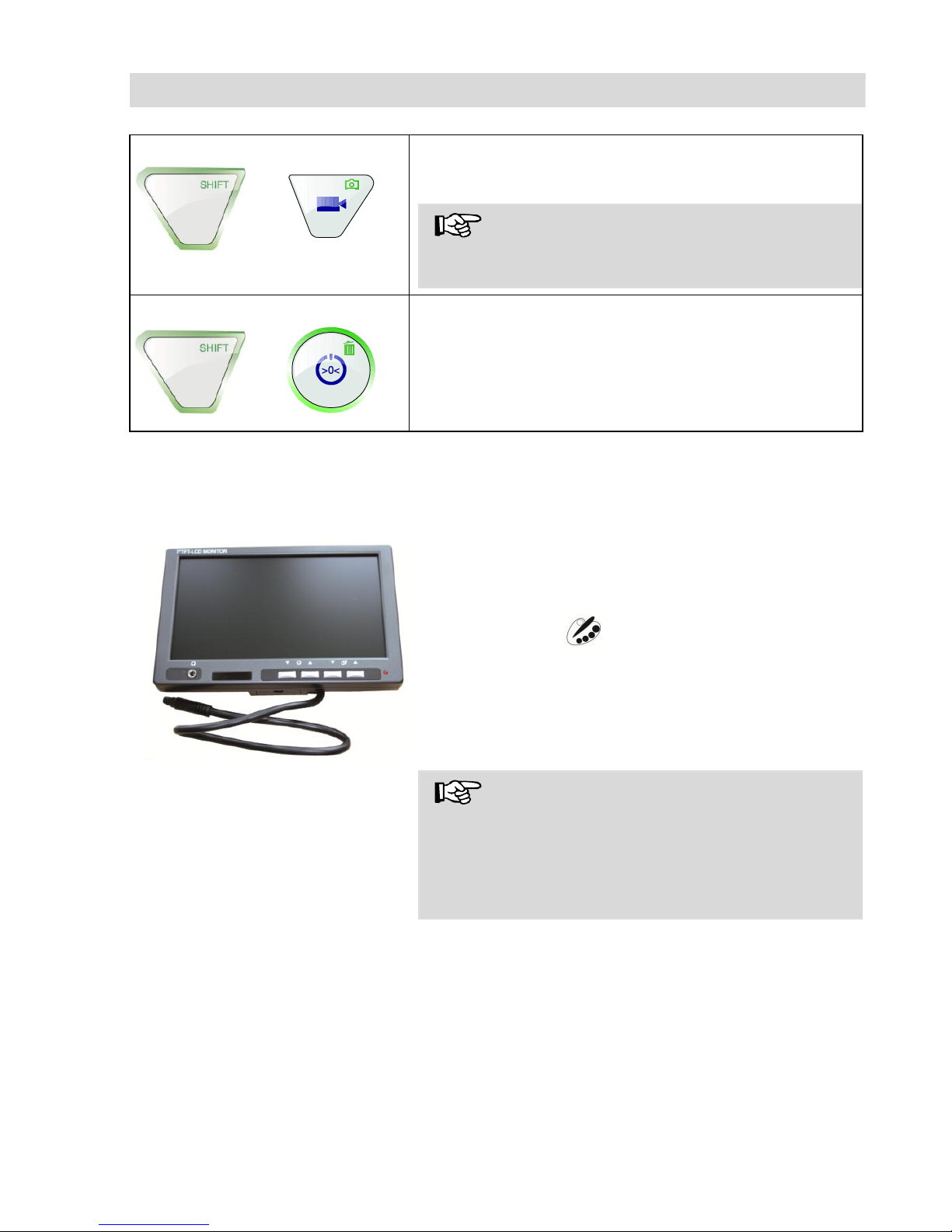
SHIFT key
Activates the key functions depicted by green icons
on the top right corners of the keys.
NOTE!
When SHIFT MODE is activate, the SHIFT key
lights up and an S is displayed in the bottom middle of the screen.
Illumination key
Dimming function to set the brightness of the camera head lighting.
NOTE!
There are three levels of brightness available to
increase or dim the intensity of the camera head
lighting. The brightness is increased each time the
user presses the ILLUMINATION key three times
in sequence. The fourth time the user presses the
key, the lighting returns to the lowest level of
brightness.
MENU key:
Make settings
PLAY key
Playback recorded videos
HOME key (only Wöhler VIS 350, Wöhler VIS
250: without function):
Aligns the camera head to a straight position –
displays view parallel to the ground above
+
+
+
+
Page 18
Design and function
18
IMAGE key
Capture image / snapshot
NOTE!
Images are saved in .jpg format. It is possible to
display the images on a PC from the SD card.
DELETE key
Delete an image or video selected in PLAY mode.
6.3 Monitor
6.3.1 Adjusting the Color
Fig. 10: Monitor
With the keys ▼☼▲☼▲ the brightness can be adjust-
ed.
▼▼: darker ▲▲: brighter
With the keys ▼▲ ▲▼ the color intensity can be
adjusted.
▼▼: decreasing color intensity up to black and white.
▲▲: increasing color intensity
NOTE!
We recommend not to change the monitor settings. It is also possible to do individual settings
which have influence of the video quality in the
menu of the Wöhler VIS 350/VIS 350 , see section
8.2.
+
+
Page 19
Design and function
19
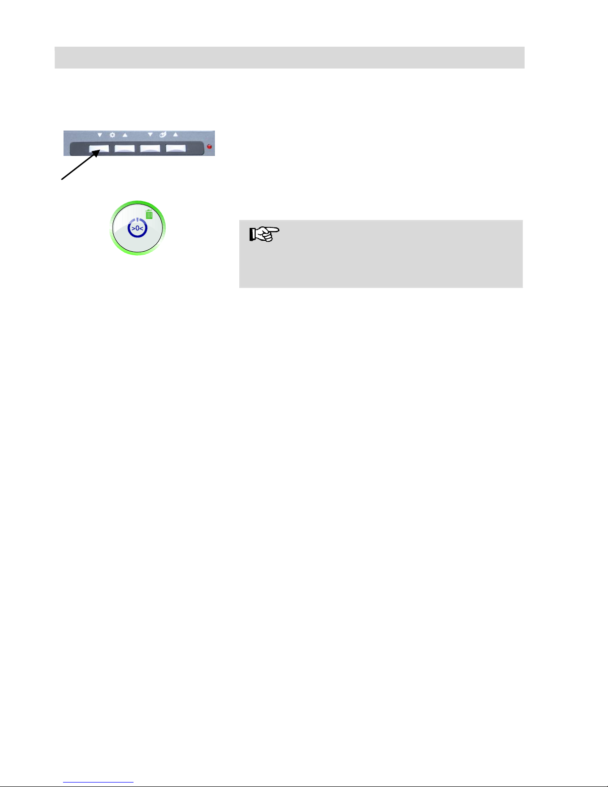
6.3.2 Transition from 16:9 Screen to 4:3 Screen
The screen format of the monitor can be changed from 16:9 to 4:3 or vice versa.
+
Switch off the camera system.
Press the left monitor key and the ON/OFF-key
of the camera at the same time.
The screen format of the monitor can be changed
from 16:9 to 4:3 or vice versa.
NOTE!
When inspecting tubes the 4:3 screen is recommended, because the widescreen 16:9 may distort
the image.
Page 20
Getting started
20
7 Getting started
7.1 Rechargeable battery
status and recharging
WARNING!
Risk of injury when handling the rechargeable
batteries improperly!
Never open the rechargeable battery housing.
Do not throw rechargeable batteries into a fire or
expose to high temperatures. There is a risk of
explosion!
If handled improperly, a liquid may emerge from
rechargeable batteries that can cause skin irritation. Avoid contact with the liquid. Rinse skin with
large amounts of water if it comes into contact
with the liquid. If the liquid comes into contact with
eyes, rinse with water immediately for 10 minutes
and consult a doctor immediately!
WARNING!
Danger of death by electrocution!
Never touch an electrical outlet with wet hands!
Do not expose the power pack to moisture!
Never pull the cable to remove the power pack
from the electrical outlet - it could rip out the cable!
Operate the power pack only when the mains
power supply is the same as the voltage stated on
the rating plate!
Rechargeable battery status
indicator
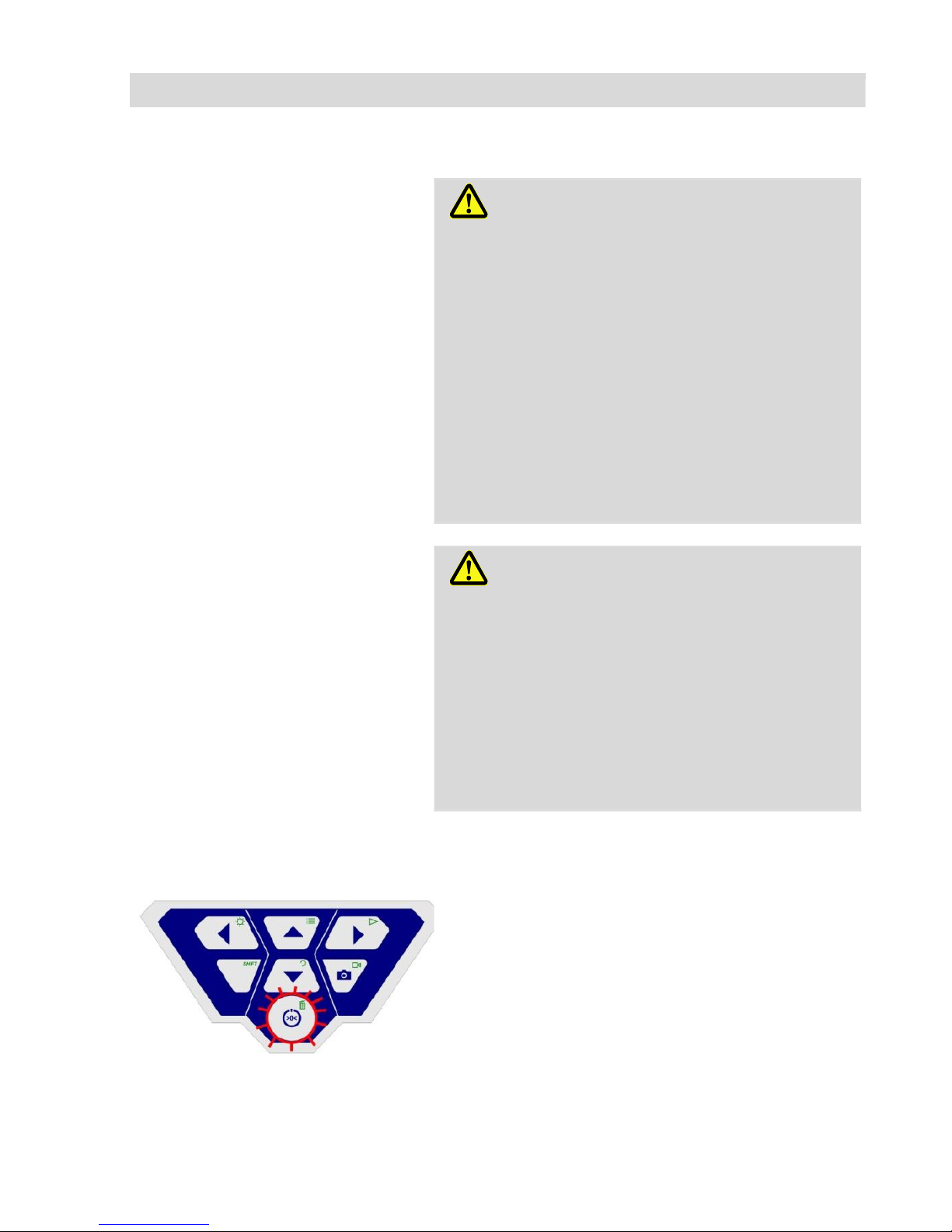
Fig. 11: Control panel of Wöhler VIS 250
/ 350 - ON/OFF key framed by flashing
light
When the camera is switched on, the battery status indicator displays the charge status of the
rechargeable battery in the top right corner of the
display. The indicator flashes when the charge
level of the batteries is low. If the charge level
continues to fall, the light framing the ON/OFF key
flashes red and the camera switches off automatically.
It is only possible to switch on the camera again
after the battery has been replaced with a charged
battery or a power cable is connected to recharge
the battery in use.
Page 21
Getting started
21
Charging rechargeable batteries
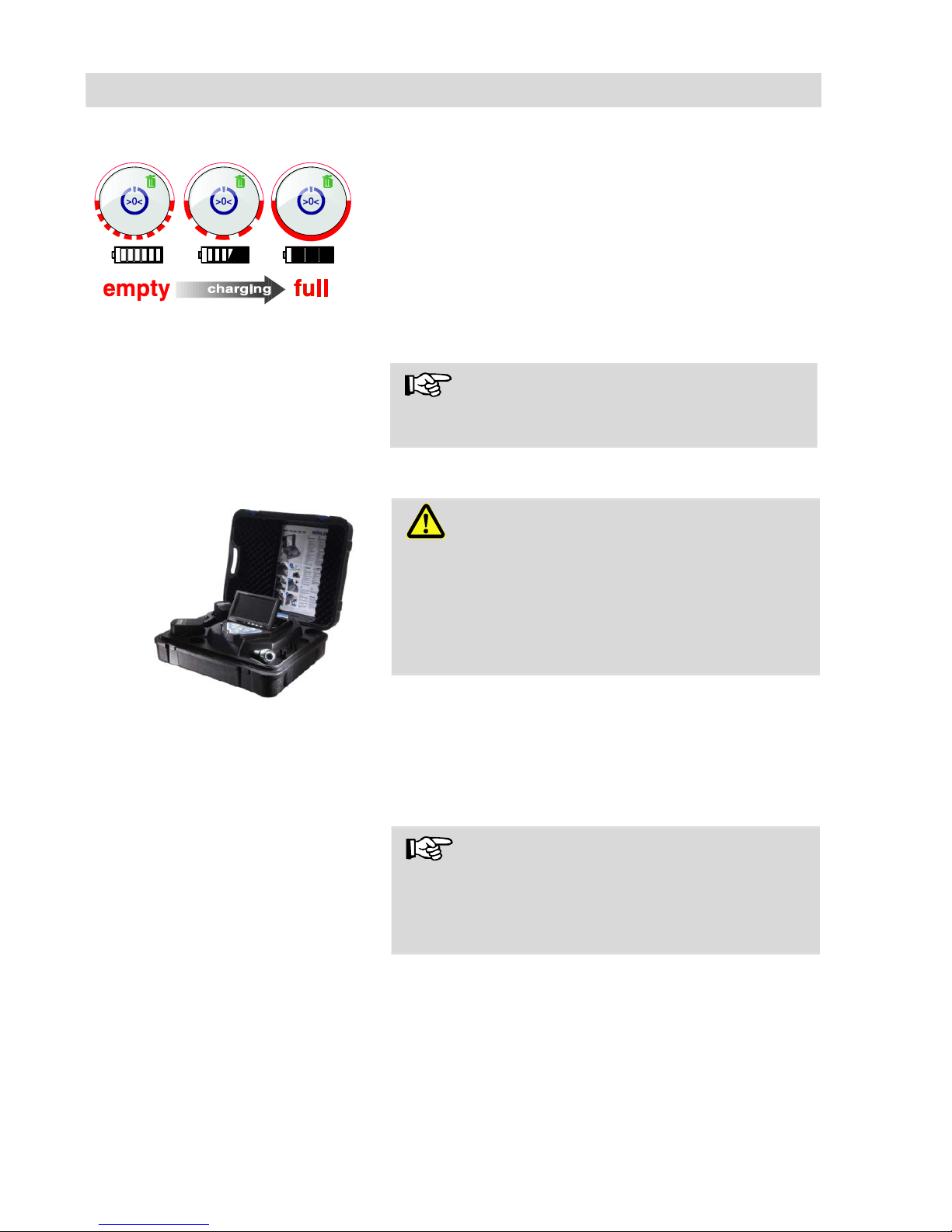
Fig. 12: Schematic overview of battery
recharging
To recharge the battery, proceed as follows:
Connect the power pack to the charger con-
nection of the device and the main power
supply.
The lower half of the light framing the ON/OFF
key flashes red during the recharging process;
when the battery is fully recharged it lights up red
continuously as long as the power pack remains
connected.
NOTE!
The operating time of the rechargeable battery is
approx. 120 minutes.
7.2 Working position
Fig. 13: possible working position
WARNING!
Only place the camera on firm level ground
and ensure a secure position of camera and
user, especially when working in high altitude,
e.g. when working on the roof. Because of its
weight the case can cause considerable harm to
persons and objects when falling down.
Place the case so that the arrows on the blue
clips show upwards.
Pull the clips and open the case
Place the monitor in the desired working posi-
tion.
NOTE!
It is possible to pull the monitor out off the support
and place it outside the case if your working position requires this. The connection cable to the case is 2 m long.
Page 22
Working with the camera
22
8 Working with the camera
8.1 Switching on the system and monitor
Wöhler VIS 250 / 350
Insert a memory card (max. 32 GB).
NOTE!
If you are using a memory card other than the one
included in the scope of supply, you must format it
first (FAT32) before you can use it on a PC.
To format the card, proceed as follows:
Insert the card into the card slot of your PC.
In the Explorer, right-click the removable me-
dia memory card, then select "Format".
Select FAT32 (default) and 32 kilobytes.
Fig. 14: ON/OFF key
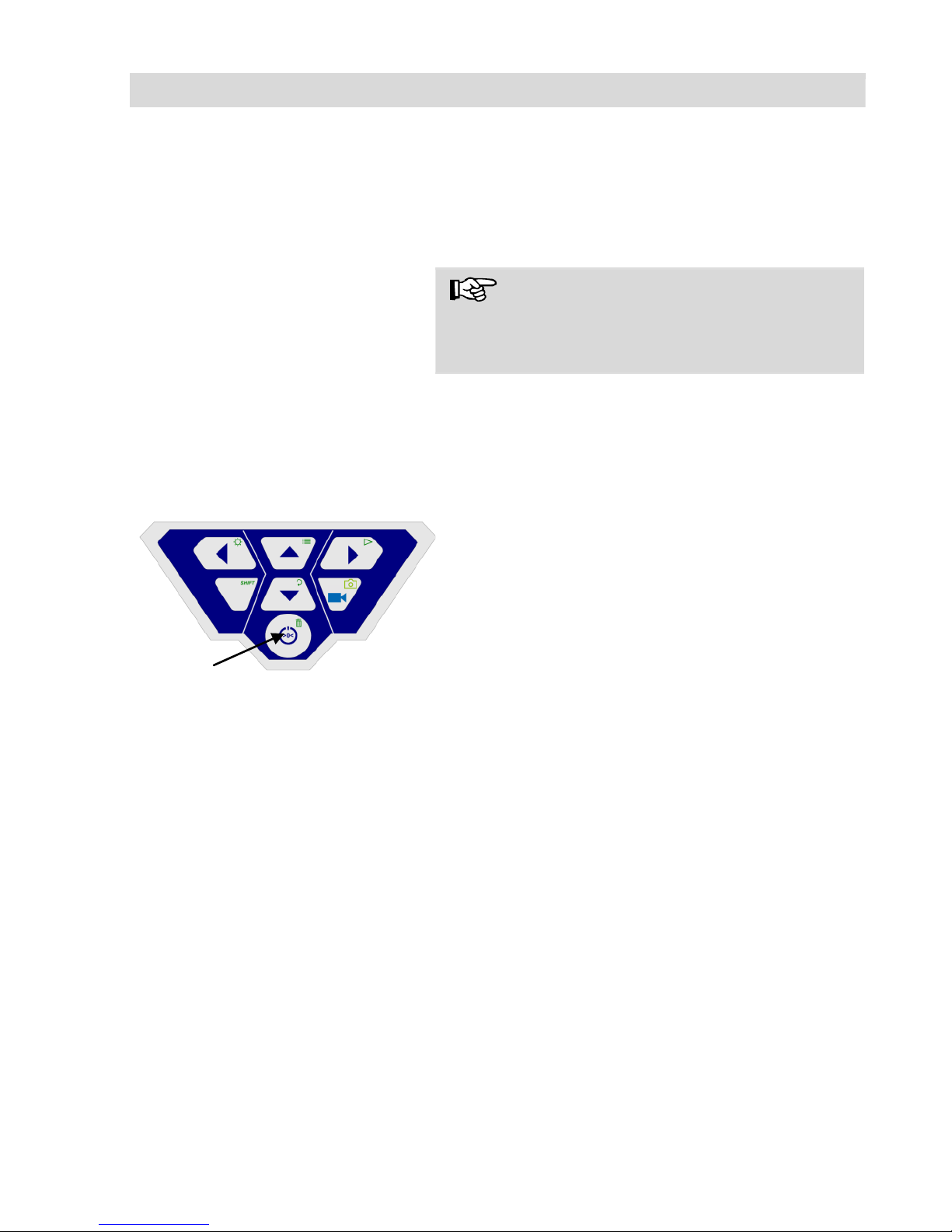
To switch on the device, briefly press the
ON/OFF key at the bottom of the control panel.
When the device is switched on, the light fram-
ing the ON/OFF key lights up green. The video
image is displayed on the monitor after about
5 seconds.
Page 23
Working with the camera
23
8.2 Memory (Wöhler VIS 250 / 350)
After switching on the device press the SHIFT
key.
The green light framing the SHIFT key lights up
and an S is displayed in the middle at the bottom
of the monitor. This indicates that SHIFT mode is
active and the second functions marked in green
on the keys are enabled.
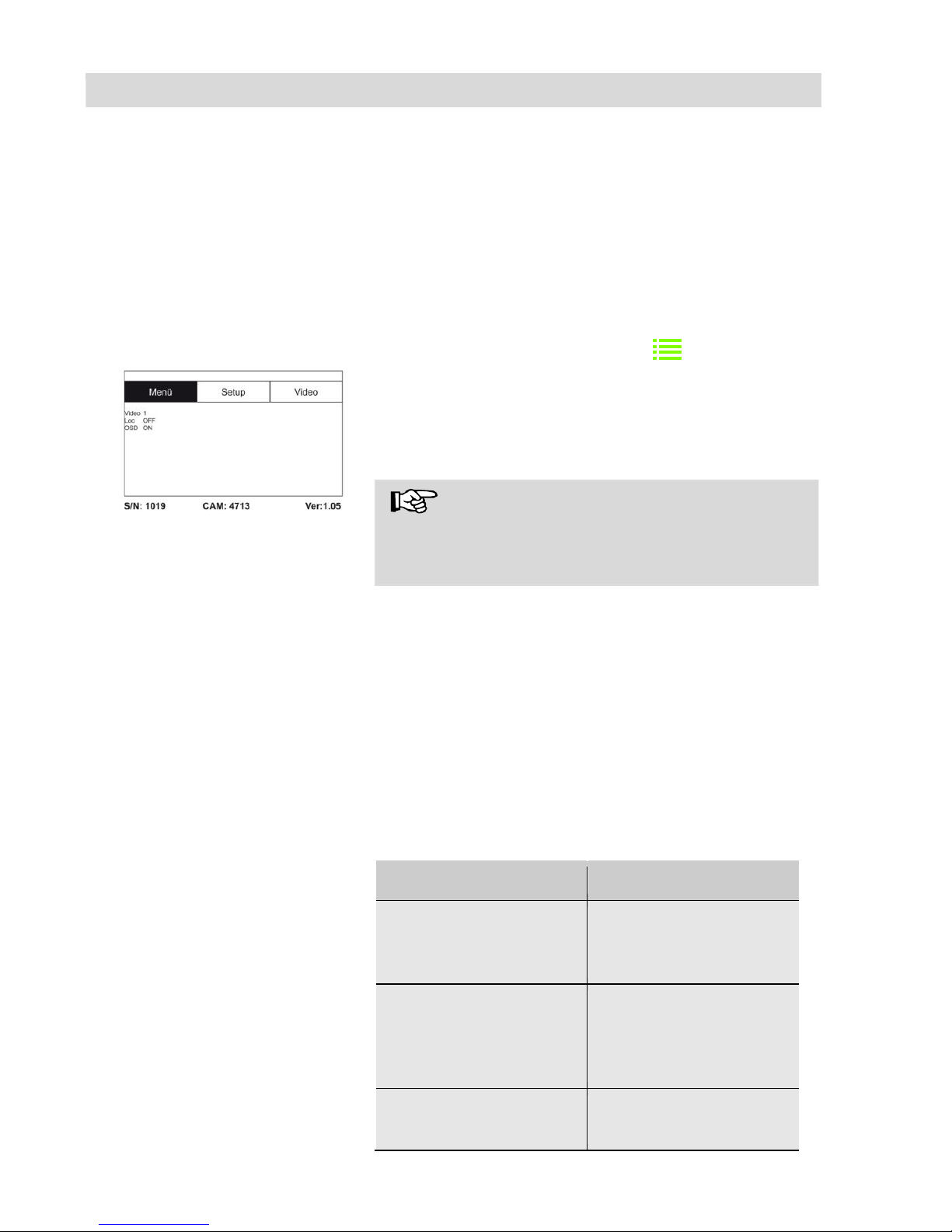
Press the Menu key
Fig. 15: Menu
The menu opposite is displayed on the screen.
Below the menu, the serial number of the camera
(S/N) the serial number of the camera head (CAM)
and the Firmware version appear on screen.
NOTE!
If you are using a camera head other than the one
included in the scope of supply, the video menu
may not be activate.
Using the up/down arrows, navigate to the
corresponding parameter. Select the desired
setting using the left/right arrow keys.
Press the ON/OFF key to confirm your selec-
tion and exit the menu.
The user can select the following parameter settings:
Video
The user is able to switch between 3 pre-defined
video settings. The settings for Video 1 and Video
2 cannot be altered.
Video
Recommended
Video 1
Recommended for
pipes, good long field
of vision
Video 2
Recommended for
chimneys; dark areas
are made to appear
brighter
Video 3
User-definable settings
Page 24
Working with the camera
24
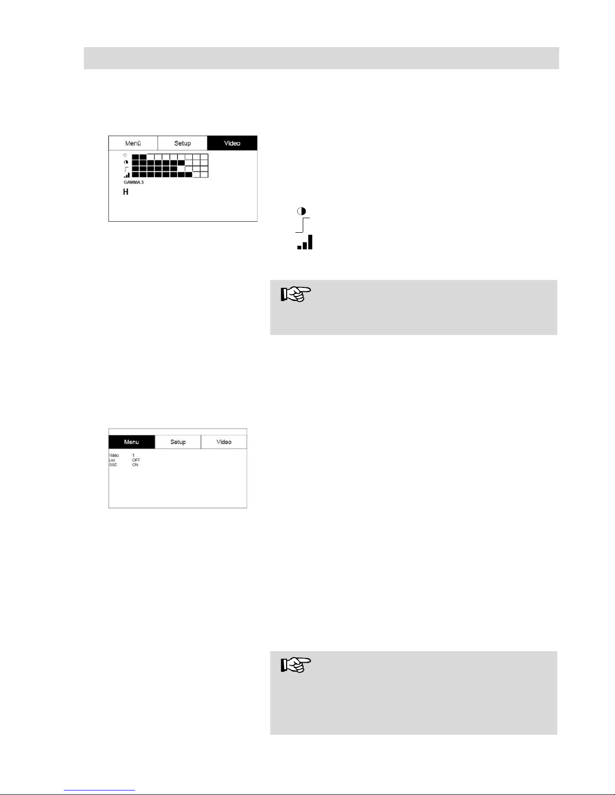
To define "Video 3" settings, proceed as follows:
Fig. 16: User-definable Video 3
settings
In the menu view, use the up arrow key to
navigate to the MENU view and then use the
right arrow key to select the Video tab.
Adjust the following settings as required:
☼ Brightness
: Contrast
: Contour sharpness
Color saturation
Gamma: Gamma curve setting (0-3)
NOTE!
Adjustments to the gamma curve affects brightness curve settings.
To save your settings, use the down arrow key
to select the disc symbol below the parameter.
Press the right or left arrow key.
This saves the settings for Video 3. The disc symbol flashes during the write operation.
Fig. 17: Menu
Return to the menu view using the arrow keys.
Loc OFF/ON
This command allows the user to switch the
transmitter integrated in the camera head on and
off. The Wöhler L 200 Locator is able to locate the
camera head with the aid of signals transmitted by
the transmitter.
ON: Transmitter is switched on
OFF: Transmitter is switched off
NOTE!
After the Wöhler VIS 250/350 has been switched
on, the transmitter will always be deactivated, because the camera consumes less power when the
transmitter is switched off.
Page 25
Working with the camera
25
Therefore the transmitter must always be switched
on before locating the camera with the Wöhler L
200 Locator.
OSD ON/OFF
This command allows the user to switch the onscreen display On or Off. Select "ON" if you wish
to display the battery status indicator and the date
on-screen.
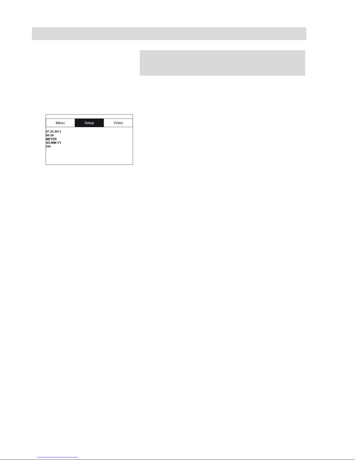
Fig. 18: Setup menu
Use the arrow keys to navigate to the Setup menu.
The following user-definable settings are available
here:
Date
Set the date. The date the recording is made is
displayed
Time
Set the time. The time the recording is made is
displayed
Meter/feet
Set the distance displayed on the screen to meters
or feet.
Date format
Set the date format to either Day.Month.Year or
Month/Day/Year
Time 12h/24h
Set the time format to either 12 hour format or 24
hour format.
Exit menu
To exit the menu, press the ON/OFF key.
Page 26
Working with the camera
26
8.3 Inspection
Pull the rod smoothly out of the case and push
the camera head to the area to be inspected.
CAUTION!
Do not exceed rod end limit!
Do not bend or drag across sharp edges!
CAUTION!
Dry and clean the rod with a cloth before pulling it
back, so that no dirt and soot can enter!
8.4 Information displayed on the monitor
8.4.1 Displaying the position of the camera head (Wöhler VIS 250/350)
Pointer symbol
Fig. 19: Display with pointer symbol and number of degrees
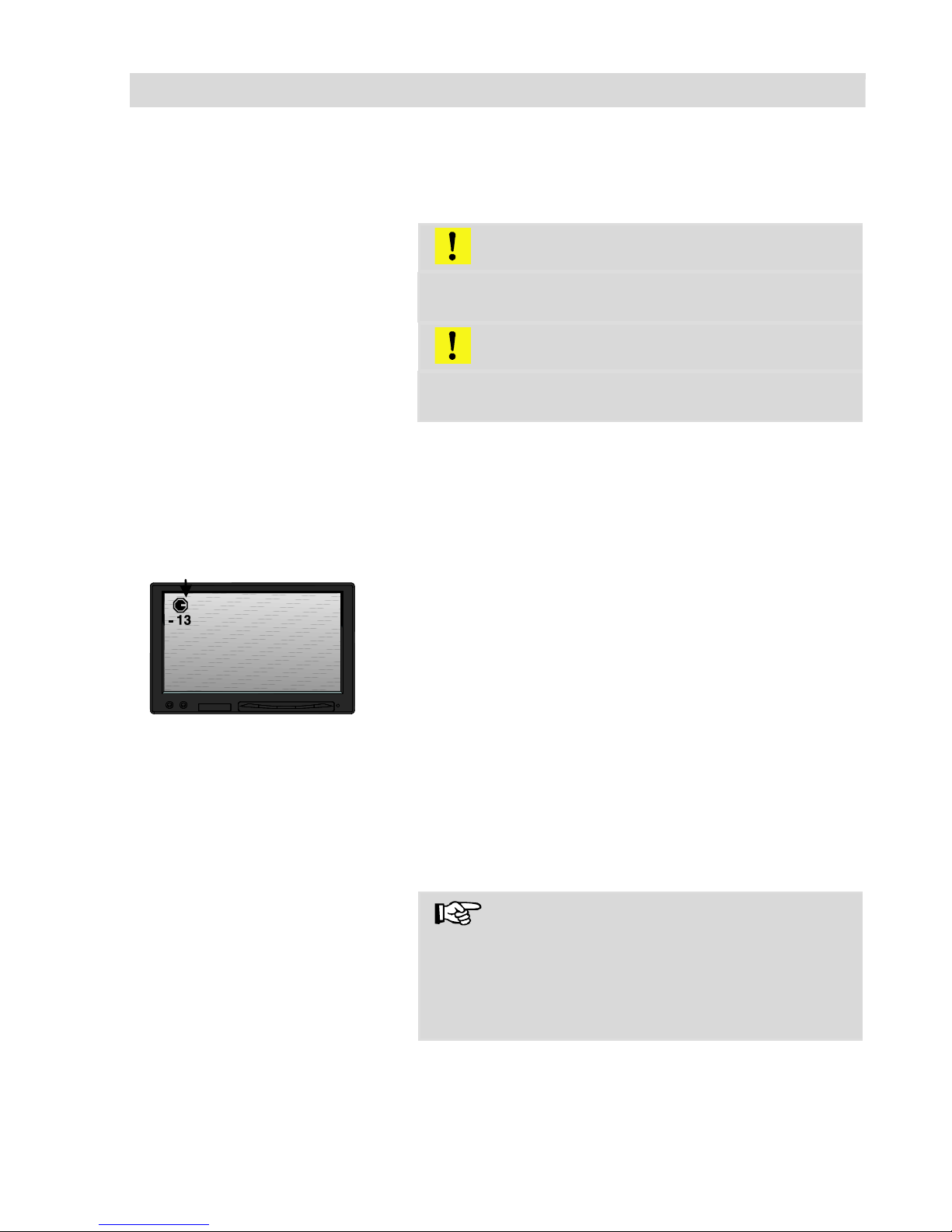
A pointer symbol displayed in the top left corner
of the screen always indicates the direction of
gravity, meaning, towards the bottom. This ensures the user is able to recognize where top and
bottom are in the pipe.
A circle is displayed around the symbol if the camera head faces vertically upwards.
A cross is displayed in the middle of the symbol if
the camera head faces vertically downwards.
Number of degrees
The number of degrees displayed underneath
indicates the downward gradient of the pipe.
Example graphic: - 13° corresponds to a downward grade of 13°.
NOTE!
Example:
Camera head facing vertically upwards: + 90°
Camera head facing vertically downwards: -90°
Camera head is aligned parallel to the ground
above: 0°
Distance counter
The distance indicated at the lower left shows how
many feet of the rod are already pulled out of the
case.
You can select the unit meter or feet in the menu,
Page 27
Working with the camera
27
see section 8.2.
NOTE!
Briefly press the ON/OFF key to reset the distance
counter to zero. This may be reasonable at the
beginning of the pipe.
Time and date
The time and date are displayed in the bottom
right corner. The recorded time is displayed when
the video is played back.
8.5 Home Function (only Wöhler VIS 350)
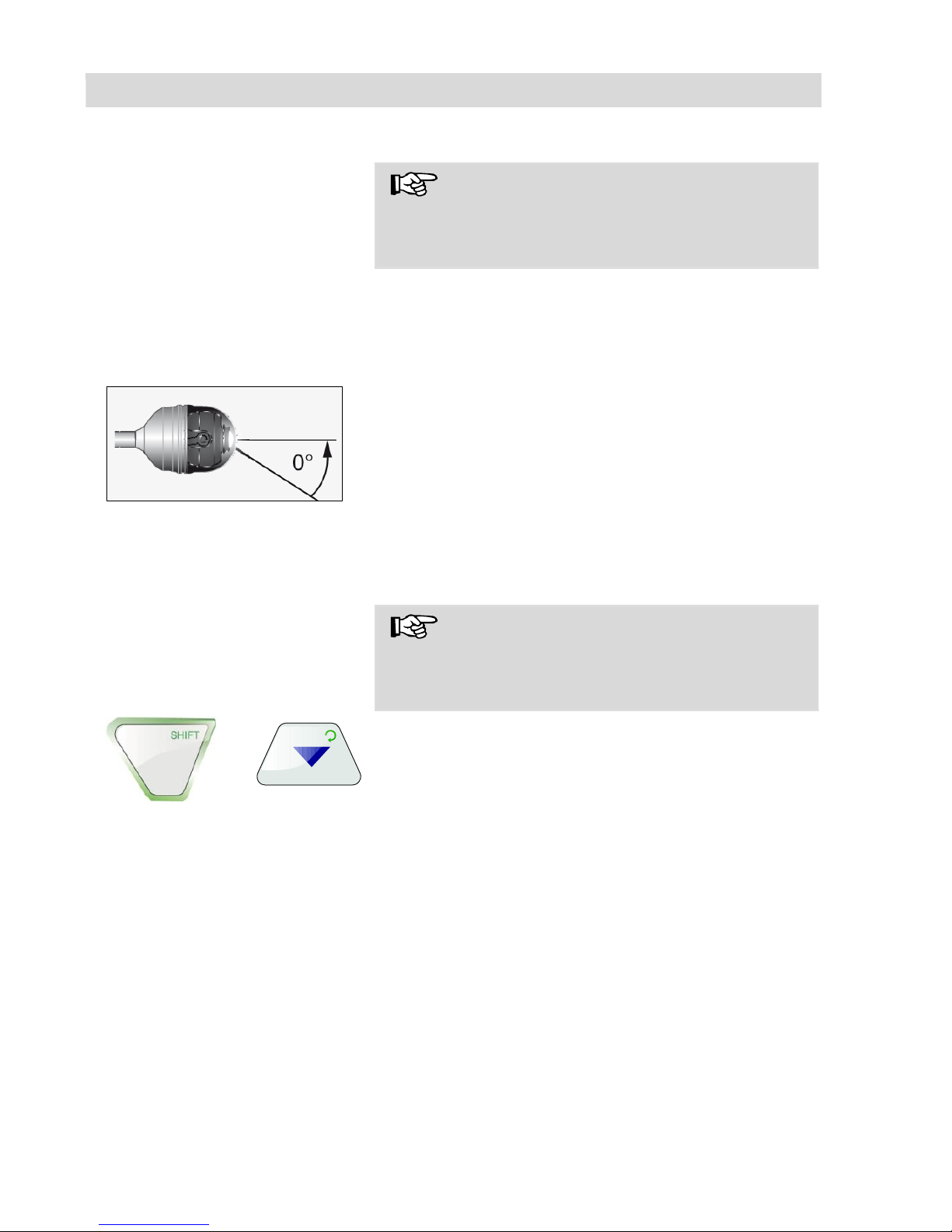
The home function ensures the camera head is
automatically aligned to a straight position, ensuring the camera "looks straight ahead".
Moreover, when the user presses the HOME key,
the camera head aligns itself so that the display is
parallel with the ground above (this function is
deactivated if the camera head faces 90° upwards
or downwards. Under these circumstances, the
optics can only be guided forwards).
NOTE!
To determine the grade described under paragraph 8.4.1, the camera head must be aligned
straight.
To activate the home function, press the
SHIFT key and then the HOME key.
Fig. 20: Home function
+
Page 28
Working with the camera
28
8.6 Video Record (Wöhler VIS 250 / 350)
Record video
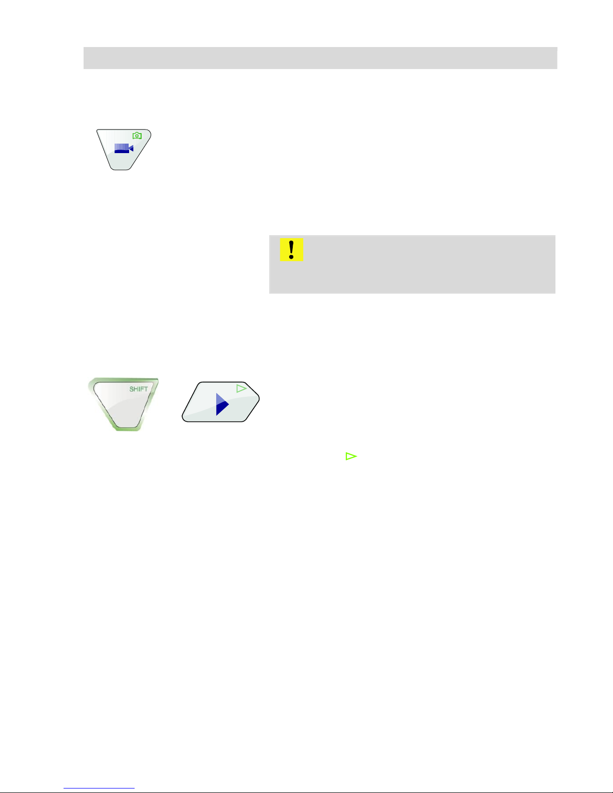
To begin recording a video, press the Record
video key.
The RECORD VIDEO key is framed by a red
flashing light when recording is in process, and a
red dot is displayed on the screen.
To stop recording, press the Record video key
again. The video is stored in ASF format on
the memory card.
CAUTION!
Ensure the power supply is not interrupted when
recording a video.
8.7 Video playback (Wöhler VIS 250 / 350)
Video playback
To playback a recorded video, press the
SHIFT key and then the PLAY key. The first
image of the last video recorded is displayed
on the screen.
Select the desired video using the right/left arrow
keys.
To begin playing back the video, press the
Play key .
+
Page 29
Images (Wöhler VIS 250 / 350)
29
9 Images (Wöhler VIS 250 / 350)
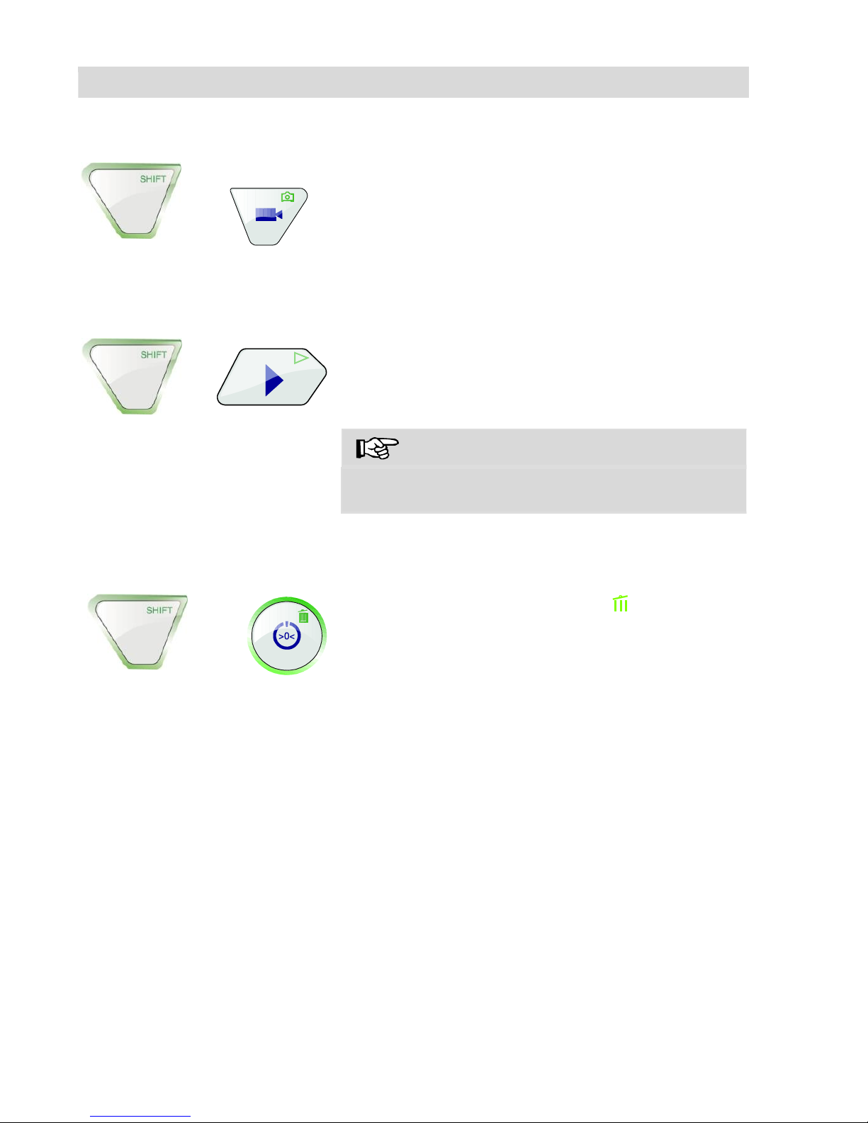
To capture an image, press the SHIFT key
and then the PHOTO key.
The image is saved as a .jpg file on the memory
card.
10 Delete a Video (Wöhler VIS 250 / 350)
To select the file to be deleted , press the
SHIFT key and then the PLAY key.
The first image of the last video recorded or the
last image recorded is displayed on the monitor.
Note!
An Icon in the upper left side of the display will
show if it is an image or a video.
Select the video or image to be deleted using
the right/left arrow keys.
To delete the video or image, press the SHIFT
key and then the DELETE key .
The prompt "DELETING FILE" is displayed on the
screen for approximately 2 seconds. Once the file
has been deleted, the image currently being
transmitted from the camera head is displayed on
the screen.
+
+
+
Page 30

Transferring images and videos to a PC
(Wöhler VIS 250/350)
30
11 Transferring images and videos to a PC
(Wöhler VIS 250/350)
Two options are available to transfer image files
(.jpg) and video files (ASF):
Read in the files on a PC from the SD memory
card.
Transfer the files to the PC using the USB
cable.
NOTE!
Image files can only be viewed and deleted on a
PC.
Page 31
Video Playback at PC (Wöhler VIS 250/350)
31
12 Video Playback at PC (Wöhler VIS 250/350)
12.1 Installing the
VLC viewer
Put the CD included in the camera system into
the CD drive of the PC. (the VLC viewer is also available for download free of charge via
the VLC web page).
Click Index.html. The menu opens.
Click the "Install" button.
Videos recorded in ASF format can be viewed
as soon as the viewer has been successfully
installed.
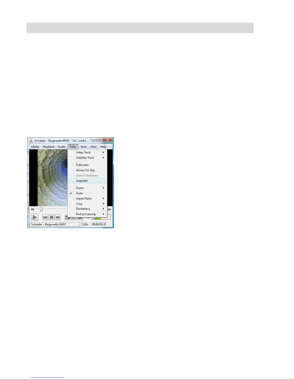
12.2 Generating snapshots
Fig. 21: Generating snapshots
To generate a snapshot from a video, click the
menu item Snapshot in the Video menu when
the video is being played back.
Page 32
Guide accessories
32
12.3 Output directory for
snapshots
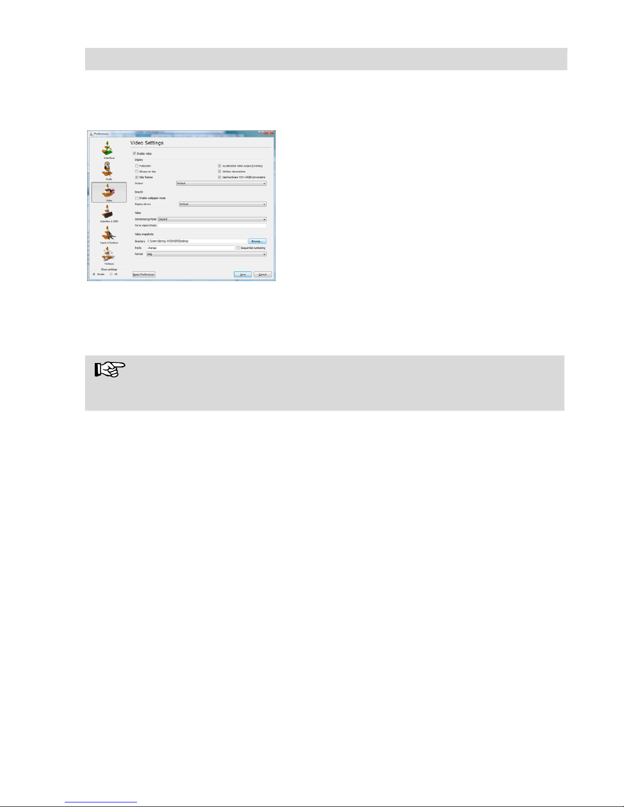
After launching the VLC Media Player, click
"Tools" and then "Preferences".
Select the "Video" symbol on the left.
In the "Take video snapshots" area, click the
"Browse ..." button and choose the folder in
which you wish to store the snapshots.
You can also select the output format of the
generated files (.png or .jpg) as well as your
own prefix to be appended to the beginning
of the file name.
To save your "preferences", click save.
As the VLC Media Player is a free ("open source")
software program, we are unable to offer any
technical support. For further information about
the program as well as the current version, visit
the developers' website at www.videolan.org
NOTE!
You can also use "Daum PotPlayer" to view videos as an alternative to the VLC Media
Player. This program is also available free of charge over the Internet.
Page 33
Guide accessories
33
13 Guide accessories
This section contains some recommendations based on our experience about the selection of guide accessories for the inspection in tubes and ducts.
As all pipes and chimney systems are different, the user has to decide about the guide
accessory in every single case. For the selection of the correct tool it is important to
consider that the guide accessory has to facilitate the introduction and the extraction of
the camera head, as well as an adequate guidance. The danger of jamming or getting
stuck in the tube has to be avoided.
NOTE!
The information given in this section only refers to the accessories.
Ø 1 ½ " – 2 "
Use the service camera without accessories.
Ø 2 " – 2,8 "
You can use the service camera without accessories. The
lens can be protected by the guidance sleeve. If there is
water and mud in the horizontal part, we recommend to use
the roller guide.
Ø 2,8 " – 3,9 "
The inspection is possible with the roller guide and without
it. Use the guidance weight for the vertical inspection or for
the inspection of downpipes.
Ø 3,9 " – 6,1 "
A centering brush can be used with the roller guide or without it and with the lens protection.
Page 34

Faults
34
14 Faults
Fault description
Possible cause
To rectify
Cannot start monitor.
When the ON/OFF key is
pressed, the light framing
the key briefly lights up
red.
Rechargeable battery has
no charge left.
Recharge battery or connect monitor to electrical
power supply.
Battery status indicator on
the monitor indicates a
low battery charge.
Rechargeable battery has
no charge left.
Replace (only Wöhler VIS
350) or recharge batteries.
The monitor is off, but the
LEDs of the camera head
are shining.
The monitor is not connected correctly.
Plug in the monitor plug.
Monitor displays black and
white
Minimal color intensity is
set.
Adjust the color intensity
of the monitor with key 4
▲:
Wöhler VIS 300/350: bad
image
Plastic dome scratched.
Replace the plastic dome;
glass dome optional.
Camera head or monitor
freezes
Battery / rechargeable
battery flat.
Replace (only Wöhler VIS
350) or recharge batteries.
Device is faulty.
Send camera system in
for repair.
Blue screen, NO SIGNAL
displayed on the monitor
Rod is broken.
Send camera system in
for repair.
Cable/plug connection at
monitor not properly connected.
Reconnect the plug connection.
Broken cables in plug
connection. Send camera
system in for repair.
Page 35
Maintenance
35
15 Maintenance
15.1 Regular maintenance
Proper operation of the camera system requires
regular maintenance. The following maintenance
works can be done by the user himself.
15.2 Changing the dome of
the Camera Head
Wöhler VIS 300/350
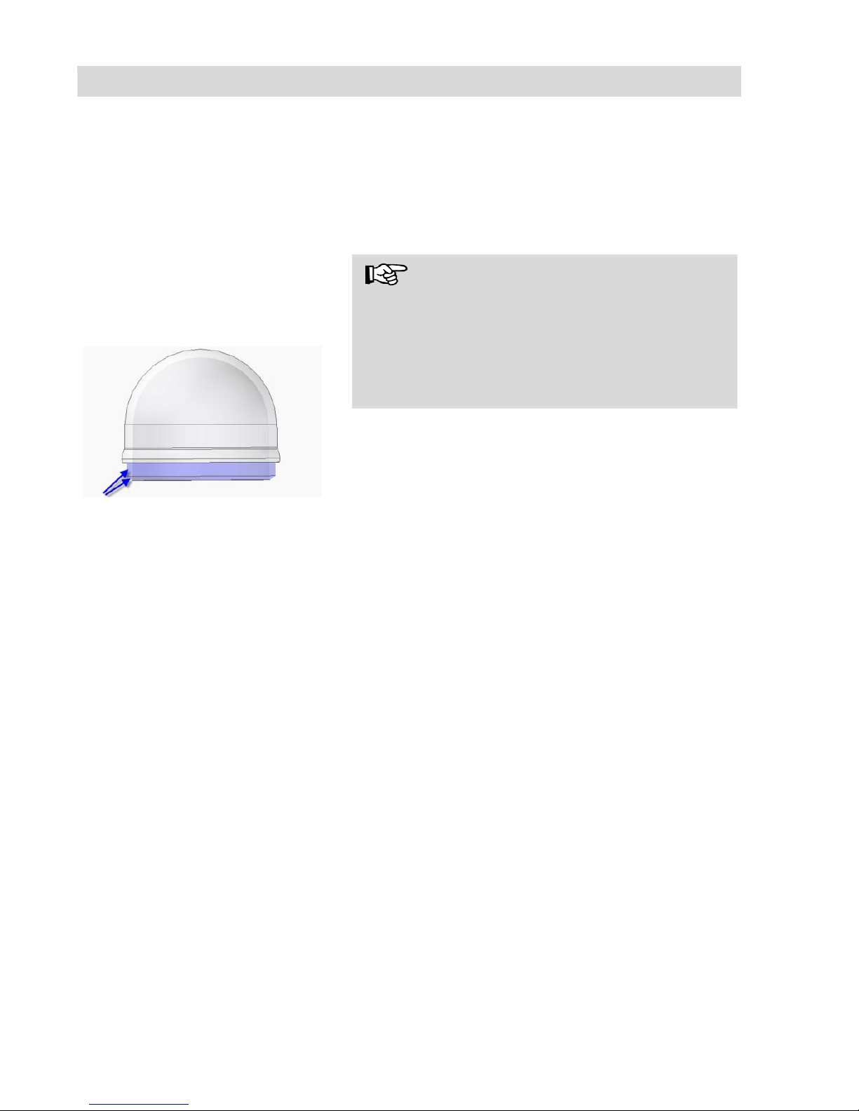
Fig. 22: Fitting the camera dome
NOTE!
The Wöhler Camera Head VIS 300/350 is supplied ex-works protected by a plastic dome, which
can be replaced if necessary. If it becomes
scratched, it is optional to fit this camera head
with a glass dome for use in dry working environments.
Apply silicone grease before fitting the new dome.
When fitting the replacement dome, make sure
you cover all of the thread to ensure it is properly
tightened. Otherwise, it cannot be guaranteed that
the camera head is properly sealed, and malfunctions can occur as a result of water and dirt penetration.
15.3 Camera head
Only use soft, damp cloth to clean the lens.
Never use any cleanser.
15.4 Push rod
Regularly pull the rod out of the case and
clean it with a soft, damp cloth.
15.5 Monitor
Clean the monitor using a soft cloth.
Page 36

Accessories
36
16 Accessories
Wöhler VIS Guidance Set 70
for miniature camera head Ø 26 mm
Order No. 3883 J
Wöhler VIS Centering Brush Extension
Order No. 3853 J
Camera Roller Guide
Order No. 3681 J
Wöhler Protection Sleeve for camera head Ø 40 mm
Order No. 2641 J
Wöhler Guidance Weight 740 g, stainless steel
Order No. 3857 J
Wöhler Guidance Ball
Order No. 3634 J
Wöhle Glass Dome for camera head Ø 40 mm
Order No. 3674 J
Wöhler Replacement Plastic Domes (10 pcs.)
for camera head Ø 40 mm
Order No. 3675 J
Anti Slide mat
Order No. 56037
L
Guidance Sleeve with protection cage
for Wöhler camera head Ø 26 mm
Order No. 3847 J
Wöhler addditional glare protection for monitor
Order No. 6814 J
Wöhler L 200 Locator (Receiver)
Order No. 7430 J
Car charger Wöhler VIS 2xx/3xx
Order No. 3169 J
Page 37

Warranty Wohler VIS Service Camera
37
17 Warranty Wohler VIS Service Camera
WohlerUSA Inc. Warranty – Please read fully!
Wohler VIS Service Camera: WohlerUSA Inc. warrants to the original end user (Customer) that this product will be free from defects in workmanship and materials, under normal
use, for one year from the date of original purchase from WohlerUSA Inc. or its author-
ized reseller. WohlerUSA Inc.’s sole obligation under this express warranty shall be, at
WohlerUSA Inc.’s option and expense, to replace the product or part with a comparable
product or part or to repair the product or part. Replacement products or parts may be
new or reconditioned. WohlerUSA Inc. warrants any repaired or replaced parts for a
period of ninety (90) days from shipment or through the end of the original warranty obligation, which ever is longer. All parts or products that are replaced become the property
of WohlerUSA Inc.
The serial number of the monitor and the camera head are printed and are needed for
any warranty claim. Please retain your invoice as proof of your warranty.
Expressly excluded from this VIS Hardware warranty are the
Glass dome that covers the lens mechanism and the camera
cable.
Obtaining Warranty Service:
The Customer must contact WohlerUSA Inc. during the normal business hours of
9:00 and 4:00 EST Monday through Friday, excluding statutory and other noted
holiday periods, within the applicable warranty period. Dated proof of purchase,
the Invoice, and the applicable serial numbers of the warranted products is required. WohlerUSA Inc. is not responsible for Customer products returned without
prior return authorization. WohlerUSA Inc. may, at its sole option, provide advance
shipment of replacement parts prior to receiving the original product or part (advance exchange). If advance exchange is not available, then the repaired product
will be shipped as soon as possible. Repaired or replaced product or parts will be
shipped at WohlerUSA Inc.’s expense. Products or parts returned by the Customer
to WohlerUSA Inc are done at their risk and must be sent prepaid and packaged
appropriately for safe shipment. It is recommended that they be insured or sent by
a method that provides for the tracking of the package. When advance exchange is
provided and the Customer fails to return the original product or part to
WohlerUSA Inc. within fifteen (15) days from the date the warranty service authorization was issued, WohlerUSA Inc. will charge the Customer the then current published catalog price of such product or part. To obtain warranty service please call
WohlerUSA Inc. at 978-750-9876 during the business hours mentioned above. You
may also go to the Wohler USA website www.wohlerusa.com and submit an RMA
request.
Page 38

Warranty Wohler VIS Service Camera
38
Warranties Exclusive:
If this product does not operate as warranted above, the Customer’s sole remedy for
breach of that warranty shall be replacement or repair of the product or part. To the full
extent allowed by law, the foregoing warranties and remedies are exclusive and are in
lieu of all other warranties, terms, or conditions, express or implied, either in fact or by
operation of law, statutory or otherwise, including warranties, terms, or conditions of
merchantability, fitness for a particular purpose, satisfactory quality, correspondence with
description, and non-infringement, all of which are expressly disclaimed. WohlerUSA Inc.
neither assumes nor authorizes any other person to assume for it any other liability in
connection with the sale, maintenance or use if its products. WohlerUSA Inc shall not be
liable under this warranty if its testing and examination of returned product shows that the
alleged defect or malfunction does not exist or was caused by the Customer’s or any
third person’s misuse, neglect, improper installation or testing, unauthorized attempts to
open, repair or modify the product or any other cause beyond the range of intended use,
or by accident, fire, or any other hazards or Acts of God. This warranty does not cover
physical damage to the surface of the product including cracks or scratches on the LCD
screen or outside casing or the leather protective case or to any cables or video rods.
This warranty does not apply when the malfunction results from the use of this product
outside of specified operating conditions or with accessories, other products, or peripheral equipment and WohlerUSA Inc. determines that there was no fault or failure of the
product itself.
Page 39

Warranty Wohler VIS Service Camera
39
Limitation of Liability: To the full extent allowed by law, WohlerUSA Inc. also excludes for itself
and its suppliers any liability, whether based on contract or Tort (Including Negligence), for incidental, consequential, indirect, special, or punitive damages of any kind for loss of business, profits,
information or data or images, or other financial loss arising out of or in connection with the sale,
installation, maintenance, use, performance, failure or interruption of this product, even if
WohlerUSA Inc. has been advised of the possibility of such damages, and limits it’s responsibility to
the replacement or repair of the product or part. This Limited Warranty is governed by the Laws of
the State of Delaware.
Wohler USA Inc.
5R Hutchinson Drive
Danvers, MA 01923
978-750-9876
Customer Name : .
Camera Case Serial # : .
Camera Head Serial # : .
Purchase Date._______________________ .
Invoice Number: .
Congratulations on your purchase of a
Wohler VIS Service Camera. Please
complete the information on this form
and retain for Warranty purposes. A
copy of this document and/or a copy of
the original invoice must accompany
any Warranty claim.
The serial number for the camera is
located on the lower metal side of the
camera. The serial number for the monitor is located on the right side of the
monitor by the cable connector.
Page 40

Points of sale and service
40
Points of sale and service
USA
Wohler USA Inc.
5 Hutchinson Drive
Danvers, MA 01923
Tel.: +1 978 750 9876
Fax.: +1 978 750 9799
www.wohlerusa.com
Germany
Wöhler Messgeräte Kehrgeräte
GmbH
Schützenstr. 41
33181 Bad Wünnenberg
Tel.: +49 2953 73-100
Fax: +49 2953 73-96100
[email protected]
www.woehler.de
Wöhler West
Castroper Str. 105
44791 Bochum
Tel.: +49 234 516993-0
Fax: +49 234 516993-99
[email protected]
Wöhler Süd
Gneisenaustr.12
80992 München
Tel.: +49 89 1589223-0
Fax: +49 89 1589223-99
[email protected]
Europe
Italy
Wöhler Italia srl
Corso Libertà 9
39100 Bolzano
Tel.: +390471402422
Fax: +39 0471
www.woehler.it
Czech Republic
Wöhler Bohemia s.r.o.
Za Naspern 1993
393 01 Pelhrimov
France
Wöhler France SARL
16 Chemin de Fondeyre
31200 Toulouse
[email protected]
 Loading...