

Wohler RMTF-170-3G-RM, RMTF-170-3G-TT User Manual

RMTF-170-3G-TT
RMTF-170-3G-RM
17.3” Audio/Video Tabletop/Rack Mount Monitors
User Guide
User Guide
Part Number 821824, Revision A

© 2018 Wohler Technologies, Inc. All rights reserved.
This publication is protected by federal copyright law. No part of this publication may be copied or
distributed, stored in a retrieval system, or translated into any human or computer language in any
form or by any means electronic, mechanical, manual, magnetic, or otherwise, or disclosed to third
parties without the express written permission of Wohler Technologies.
Reproduction
Licensed users and authorized distributors of Wohler Technologies, Inc. products may copy this
document for use with Wohler Technologies., Inc. products provided that the copyright notice above
is included in all reproductions.
Customer Support
Wohler Technologies, Inc.
31055 Huntwood Avenue
Hayward, CA 94544 www.wohler.com
Phone: 510-870-0810
FAX: 510-870-0811
US Toll Free: 1-888-596-4537 (1-888-5-WOHLER)
Web: www.wohler.com Sales: sales@wohler.com
Support: support@wohler.com
Disclaimers
Even though Wohler Technologies, Inc. has tested its equipment and software, and reviewed the
documentation, Wohler Technologies, Inc. makes no warranty or representation, either express or
implied, with respect to software, documentation, their quality, performance, merchantability, or
fitness for a particular purpose.
In no event will Wohler Technologies, Inc. be liable for direct, indirect, special, incidental, or
consequential damages resulting from any defect in the hardware, software, or its documentation,
even if advised of the possibility of such damages.
Some states do not allow the exclusion or limitation for incidental or consequential damages, so the
above exclusion or limitation may not apply to you.
Printing
This document looks best when printed on a color printer since some images may be indistinct when
printed on a black and white printer.
PDF
All text strings underlined in this shade of blue are hyperlinks within this document.
Last Update
July 23, 2018
Page 2

TABLE OF CONTENTS
Contents
User Guide..........................................................................................1
TABLE OF CONTENTS............................................................................3
Contents .........................................................................................................3
CHAPTER 1: Installation ........................................................................4
Introduction ....................................................................................................4
Overview...............................................................................................4
Features ...............................................................................................4
Safety.............................................................................................................4
Instructions ...........................................................................................4
Safety Symbols......................................................................................5
Mounting...............................................................................................5
Heat Dissipation .....................................................................................6
Sympathetic Vibration.............................................................................6
Mechanical ............................................................................................6
Electrical Interference .............................................................................6
Power ...................................................................................................6
Compliance .....................................................................................................7
FCC ......................................................................................................7
ICES-003 ..............................................................................................7
CHAPTER 2: Local Operation ..................................................................8
Front Panel......................................................................................................8
On-Screen Display Features...............................................................................9
Rear Panel.....................................................................................................11
Rear Panel Connectors ....................................................................................13
Front Panel Menu Operation.............................................................................13
Input ..................................................................................................13
Quick Menu .........................................................................................14
OSD Menus .........................................................................................14
OSD Menus ...................................................................................................15
CHAPTER 3:
Supported Video Formats ................................................................................26
Technical Info ................................................................ 25
Page 3

CHAPTER 1: Installation
Introduction
Overview
The RMTF-170-3G-TT and RMTF-170-3G-RM monitors set a new standard in LCD
monitors for broadcast and professional video applications. They provide a 17.3”,
10-bit, 1920 x 1080 resolution, 16:9 format, anti-glare IPS LCD screen. All video
formats are scaled to fit on the screen in the highest quality using 12-bit digital
processing, precision scaling, and gamma correction to produce the best images
possible. For use outdoors, an optional Sun Shade (part number 829201) is
available for the RMTF-170-3G-TT.
The RMTF-170-3G-TT is a tabletop monitor and the RMTF-170-3G-RM is a rack
mounted monitor. Except for the mounting style, these monitors are identical, so
for convenience, this manual will generally only refer to them as RMTF-170-3G.
Features
The RMTF-170-3G audio/video monitor is designed for confidence monitoring of two
3G/HD/SD-SDI inputs, one of which has a regenerated output. It also can monitor
one HDMI, and one CVBS composite analog video input. The input signals are easily
selected and displayed. Two to sixteen audio channels may be selected for visual
monitoring on bar graph style level meters. On screen markers, waveform, vector,
and histogram displays can be enabled on this full-featured monitor. Focus Assist
and Zebra modes can be engaged to assist with camera adjustments. Camera Look
Up Tables (LUT) are supported, as well. A single speaker with a left / right mix
provides audio monitoring. A headphone jack is also provided for external stereo
audio monitoring.
Parameters are selected and adjusted using an On Screen Display (OSD) Menu.
There are also four function buttons which can immediately enable or disable
selected features. These buttons can double as user preset selectors which can call
up any of four preprogrammed video setups.
Safety
Instructions
1. Read, keep, and follow all of these instructions; heed all warnings.
2. Do not use this equipment near water.
3. Use only a dry cloth to clean the equipment.
4. Do not block any ventilation openings.
5. Do not install near any heat source such as a radiator, heat register, amplifier, or
Page 4
The symbol to the left warns of
electric shock hazard inside the unit.
Important:
By design, this monitor will only
plug into a three
-
prong outlet for
stove.
6. Do not attempt to plug the unit into a two-blade outlet (with only two prongs of
equal width).
your safety. If the plug does not fit into the outlet, contact an
electrician to replace the obsolete outlet.
7. Protect the power cord from being walked on or pinched, particularly at plug
connection on the equipment and at the socket.
8. Use only the attachments/accessories specified by the manufacturer.
9. Unplug the equipment during lightning storms or when unused for long periods
of time.
10. Refer all servicing to qualified service personnel. Servicing will be required
under all of the following conditions:
a. The equipment has been damaged in any way, such as when the power-
supply cord or plug is damaged.
b. Liquid had been spilled or objects have fallen onto the equipment.
c. The equipment has been exposed to rain or moisture.
d. The equipment does not operate normally.
e. The equipment has been dropped.
Safety Symbols
Disconnect the power cord before removing access panels when
installing upgrades. Only qualified service personnel are to operate
the equipment with covers removed, and are to exercise caution to
avoid personal injury.
Mounting
The RMTF-170-3G-TT is designed to be placed on a tabletop or other flat surface.
Position either unit at ear/eye level for best high frequency response and visual
observation of the display screen. Please adhere to the clearances listed in Table 1-
1.
The RMTF-170-3G-RM is designed to be mounted in 6RU of a standard 19" rack. It
may be tilted forward for easier viewing. Position either unit at ear/eye level for
best high frequency response and visual observation of the display screen. Please
adhere to the following clearances:
Page 5

Important
Table 1-1: Recommended Clearances
Clearance
Surface
24” Front
3” Rear
2” Sides
1.75” Top and Bottom (if near other equipment)
0” Top and Bottom (if no other equipment)
Heat Dissipation
The ambient temperature near the product should not exceed 40° Celsius (104°
Fahrenheit). When rack mounting, adjacent devices can be rack mounted in
proximity to the unit if this temperature is not exceeded. Otherwise, allow a 1RU
(1.75”/44.45mm) space above and below the unit for air circulation. For table top
operation, in warm environments, allow an inch of space above and below the unit
for air circulation.
The heat generated by the digital circuitry, power supplies, and
other components is vented by slots in the back of the unit.
Therefore, as a safety precaution, you must allow proper
ventilation on these surfaces.
Sympathetic Vibration
Sympathetic vibration from other equipment (cables, etc.) in the rack may be
serious enough to interfere with the unit’s sound quality. If you experience
sympathetic vibrations, use thin card stock, felt, foam, or weather-stripping
between the vibrating surfaces. Tie loose cables securely with cable ties.
Mechanical
The sturdy chassis is very shallow from front to back making it very stable when
used with its table stand. It can be tilted forward or backward for viewing, if
necessary. The weight of internal components is distributed fairly evenly around the
unit.
Electrical Interference
Be careful to avoid mismatched cable types and other similar causes of undesired
reflections in digital signal systems. If severe enough, such reflections can result in
corruption of the digital data stream. As with any audio equipment, maximum
immunity from electrical interference requires the use of shielded cable; however,
satisfactory results can sometimes be obtained without it. The internal circuitry
ground is connected to the chassis.
Power
The unit connects to the AC mains power source (14W, 100 to 240 VAC, ±10%,
Page 6

50/60Hz) through the IEC connector provided on the rear panel. Alternately, it can
be powered from a camera battery, which installs on the rear panel.
When the mains plug or appliance coupler is used as the disconnect device, the
disconnect device should remain operable.
Compliance
FCC
This equipment has been tested and found to comply with the limits for a Class A
digital device, pursuant to part 15 of the FCC Rules. These limits are designed to
provide reasonable protection against harmful interference when the equipment is
operated in a commercial environment. This equipment generates, uses, and can
radiate radio frequency energy and, if not installed and used in accordance with the
instruction manual, may cause harmful interference to radio communications.
Operation of this equipment in a residential area is likely to cause harmful
interference, in which case the user will be required to correct the interference at
their own expense.
ICES-003
This Class A digital apparatus complies with Canadian ICES-003.
Cet appareil numérique de la classe A est conforme à la norme NMB-003 du
Canada.
Page 7
CHAPTER 2: Local Operation
The RMTF-170-3G front and rear panels are described in this chapter.
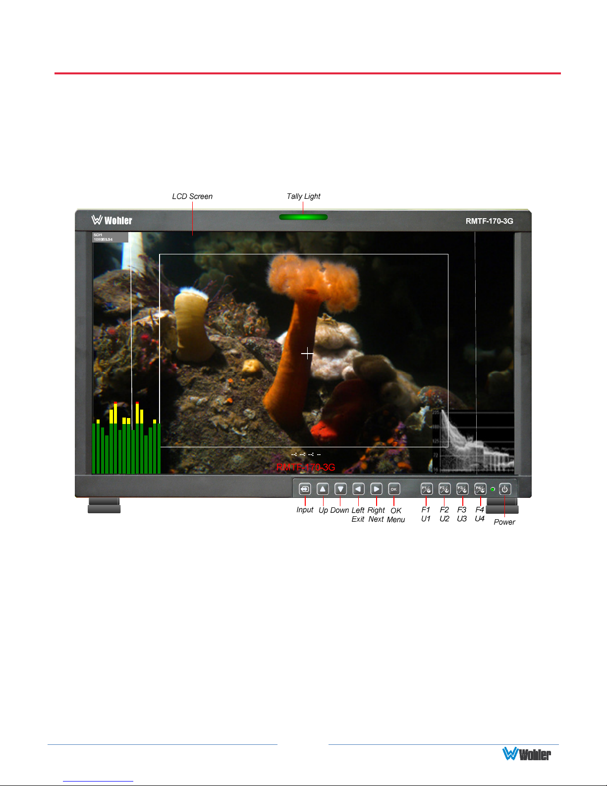
Front Panel
Figure 2–1: Front Panel Layout
1. Tally Lights: This tri-color (red/green/amber) light is controlled through a RJ45
connector on the rear panel. For more information about the RJ45 connector,
refer to the Rear Panel section of this chapter. When first connected to power,
the Tally Light glows amber until the unit is ready for operation.
2. LCD Screen: The LCD screen displays the audio meters, waveform, vector, or
histogram displays, menus, and OSD features superimposed over the video.
3. Power: The Power button turns the LCD screen to On or Standby mode. The
adjacent Power Indicator glows green to indicate On and red to indicate
Standby. To prevent the operator from accidentally switching the monitor to
Standby mode, the Power button must be held for 2 seconds.
4. Input: The Input button selects the video/audio input to be monitored from the
Page 8
various connectors on the rear panel. The currently selected input source is
indicated when the Input button is pressed. Repeated presses change the input
source.
5. F1/U1, F2/U2, F3/U3, F4/U4 Function/User Keys: These keys are dual
purpose. Momentarily pressing F1, F2, F3, or F4 will activate the assigned
function. The default assignments are as listed in Table 2-1. The action of each
Function Key can be selected from a wide variety of actions in the Function Key
Menu as described in Table 2-9. Holding U1, U2, U3, or U4 for 2 seconds will
instead activate the User Preset associated with the key. Refer to Table 2-9.
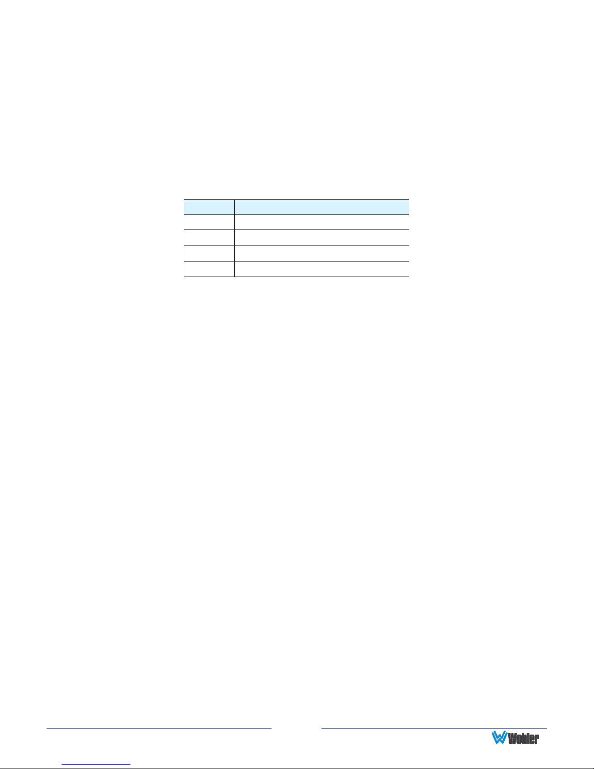
Table 2-1: Default Function Key Actions
Key
Default Action
F1 Scan
F2 Marker
F3 Audio Meters
F4 Blue Only
6. OK/Menu: Press this button to display the OSD Menu. Refer to the OSD
Menus section of this chapter for operation and content of these menus. When
the OSD Menu is displayed, pressing this button accepts selections in the menus
and sub-menus.
7. Down: When the OSD Menu is not being displayed, pressing this button
displays the Quick Menu, which cycles through frequently used volume and
image controls. Refer to the Quick Menu section of this chapter. When the OSD
Menu is displayed, the Down button navigates down through the menu and
sub-menu selections and can be used to adjust the settings.
8. Up: When the OSD Menu is displayed, the Up button navigates down through
the menu and sub-menu selections and can be used to adjust the settings. It
also adjusts the items in the Quick Menu.
9. Left/Exit: In the OSD Menu, this button backs out of selections. In the Quick
Menu, this button reduces the value of any selection.
10. Right/Next: In the OSD Menu, this button advances into selections, or
advances to the next menu page. In the Quick Menu, it increases the value of
any selection.
On-Screen Display Features
Functions and parameters can be selected and adjusted using the On Screen
Display (OSD) Menu. Refer to the OSD Menus section of this chapter.
Overlays can be added by the operator for Area & Safety Markers, Center
Marker, and to display names as IMD (In Monitor Display) for identification.
Video effects such as Monochrome, Blue Only, Focus Assist, False Color
Exposure Assist, and other features can be used to assist setup. For convenience
and quicker access, these and other features can be assigned to the Function
Keys.
Page 9
 Loading...