

Wohler HDM-215-3G-TT, RMT-230-3G-TT User Manual

HDM-215-3G-TT
21.5” Audio/Video Tabletop Monitor
User Guide
User Guide
Part Number 821818, Revision A

© 2016 Wohler Technologies, Inc. All rights reserved.
This publication is protected by federal copyright law. No part of this publication may be copied or
distributed, stored in a retrieval system, or translated into any human or computer language in any
form or by any means electronic, mechanical, manual, magnetic, or otherwise, or disclosed to third
parties without the express written permission of Wohler Technologies.
Reproduction
Licensed users and authorized distributors of Wohler Technologies, Inc. products may copy this
document for use with Wohler Technologies., Inc. products provided that the copyright notice above
is included in all reproductions.
Customer Support
Wohler Technologies, Inc.
31055 Huntwood Avenue
Hayward, CA 94544 www.wohler.com
Phone: 510-870-0810
FAX: 510-870-0811
US Toll Free: 1-888-596-4537 (1-888-5-WOHLER)
Web: www.wohler.com Sales: sales@wohler.com
Support: support@wohler.com
Disclaimers
Even though Wohler Technologies, Inc. has tested its equipment and software, and reviewed the
documentation, Wohler Technologies, Inc. makes no warranty or representation, either express or
implied, with respect to software, documentation, their quality, performance, merchantability, or
fitness for a particular purpose.
In no event will Wohler Technologies, Inc. be liable for direct, indirect, special, incidental, or
consequential damages resulting from any defect in the hardware, software, or its documentation,
even if advised of the possibility of such damages.
Some states do not allow the exclusion or limitation for incidental or consequential damages, so the
above exclusion or limitation may not apply to you.
Printing
This document looks best when printed on a color printer since some images may be indistinct when
printed on a black and white printer.
PDF
All text strings underlined in this shade of blue are hyperlinks within this document.
Other Technologies and Products
Google Chrome is a registered trademark of Alphabet Inc. Microsoft Windows and Internet Explorer
are registered trademarks of Microsoft Corporation. Evertz and MAGNUM are registered trademarks
of Evertz Microsystems Ltd.
Last Update
December 13, 2016
Page 2

TABLE OF CONTENTS
Contents
User Guide..........................................................................................1
TABLE OF CONTENTS............................................................................3
Contents .........................................................................................................3
CHAPTER 1: Installation ........................................................................5
Introduction ....................................................................................................5
Overview...............................................................................................5
Features ...............................................................................................5
Safety.............................................................................................................5
Instructions ...........................................................................................5
Safety Symbols......................................................................................6
Mounting...............................................................................................6
Heat Dissipation .....................................................................................7
Sympathetic Vibration.............................................................................7
Mechanical ............................................................................................7
Electrical Interference .............................................................................7
Power ...................................................................................................7
Compliance .....................................................................................................8
FCC ......................................................................................................8
ICES-003 ..............................................................................................8
CHAPTER 2: Local Operation ..................................................................9
Front Panel......................................................................................................9
On-Screen Display Features.............................................................................10
Rear Panel .....................................................................................................12
Rear Panel Connectors ....................................................................................15
Using the Quick Menu and the OSD Menus ........................................................16
Quick Menu .........................................................................................16
OSD Menus .........................................................................................16
OSD Menus ...................................................................................................17
CHAPTER 3:
Supported Video Formats ................................................................................31
Technical Info ................................................................ 29
CHAPTER 4: Using Network Control ...................................................... 32
Web Browser / Control Device .........................................................................32
First Time- IP Assignments..............................................................................32
Status Page ...................................................................................................33
Adjust Page ...................................................................................................35
Video Display Page .........................................................................................35
Input Setup Page ........................................................................................... 36
Page 3

Marker Page ..................................................................................................37
Audio Page ....................................................................................................38
Display Page..................................................................................................39
Close Caption Page.........................................................................................39
Config Page ...................................................................................................40
Color Temperature Page..................................................................................41
Function Key Page ..........................................................................................41
IMD Page ......................................................................................................42
GPI Page .......................................................................................................43
System Page .................................................................................................44
Page 4

CHAPTER 1: Installation
Introduction
Overview
The HDM-215-3G-TT monitor sets a new standard in LCD monitors for broadcast
and professional video applications. It provides a 21.5”, 8-bit, 1920 x 1080
resolution, 16:9 format, anti-glare IPS LCD screen. All video formats are scaled to
fit on the screen in the highest quality using 12-bit digital processing, precision
scaling and gamma correction to produce the best images possible.
Features
The HDM-215-3G-TT audio/video monitor is designed for confidence monitoring of
two 3G/HD/SD-SDI, one HDMI/DVI, one CVBS composite analog video, and one Y/C
and component input. Input signals are easily selected and displayed. Two to
sixteen audio channels may be selected for visual monitoring on bar graph style
level meters. On screen markers, waveform, vector, Picture in Picture (PiP) and
Picture by Picture (PbP) displays can be enabled on this full-featured monitor.
Focus Assist and Luma Zone modes can be engaged to assist with camera
adjustments. Stereo speakers provide audio monitoring. A headphone jack and
stereo analog audio outputs are also provided for external audio monitoring.
Parameters are selected and adjusted using an On Screen Display (OSD) Menu. An
RJ45 connector serves as the interface to six general purpose inputs which can be
optioned to control a variety of monitor functions. Monitor settings can also be
made with a web browser over Ethernet using the integral web server.
Safety
Instructions
1. Read, keep, and follow all of these instructions; heed all warnings.
2. Do not use this equipment near water.
3. Use only a dry cloth to clean the equipment.
4. Do not block any ventilation openings.
5. Do not install near any heat source such as a radiator, heat register, amplifier, or
stove.
6. Do not attempt to plug the unit into a two-blade outlet (with only two prongs of
equal width).
Page 5
The symbol to the left warns of electric shock hazard
inside the unit.
Important:
By design, this monitor will only plug into a three
-
prong outlet fo
r
your safety. If the plug does not fit into the outlet, contact an
electrician to replace the obsolete outlet.
7. Protect the power cord from being walked on or pinched, particularly at plug
connection on the equipment and at the socket.
8. Use only the attachments/accessories specified by the manufacturer.
9. Unplug the equipment during lightning storms or when unused for long periods
of time.
10. Refer all servicing to qualified service personnel. Servicing will be required
under all of the following conditions:
a. The equipment has been damaged in any way, such as when the power-
supply cord or plug is damaged.
b. Liquid had been spilled or objects have fallen onto the equipment.
c. The equipment has been exposed to rain or moisture.
d. The equipment does not operate normally.
e. The equipment has been dropped.
Safety Symbols
Disconnect the power cord before removing access panels when
installing upgrades. Only qualified service personnel are to operate
the equipment with covers removed, and are to exercise caution to
avoid personal injury.
Mounting
The HDM-215-3G-TT is designed to be placed on a tabletop or other flat surface.
Position either unit at ear/eye level for best high frequency response and visual
observation of the display screen. Please adhere to the following clearances:
Table 1-1: Recommended Clearances
Clearance
Surface
24” Front
3” Rear
2” Sides
1.75” Top and Bottom (if near other equipment)
0” Top and Bottom (if no other equipment)
Page 6

Important
supplies, and other components is vented by slots in the back of
Heat Dissipation
The ambient temperature near the product should not exceed 40° Celsius (104°
Fahrenheit). When rack mounting, adjacent devices can be rack mounted in
proximity to the unit if this temperature is not exceeded. Otherwise, allow a 1RU
(1.75”/44.45mm) space above and below the unit for air circulation. For table top
operation, in warm environments, allow an inch of space above and below the unit
for air circulation.
To reduce noise, the monitor does not have any fans. As a
result, the heat generated by the audio amplifiers, power
the unit. Therefore, as a safety precaution, you must allow
proper ventilation on these surfaces.
Sympathetic Vibration
Sympathetic vibration from other equipment (cables, etc.) in the rack may be
serious enough to interfere with the unit’s sound quality. If you experience
sympathetic vibrations, use thin card stock, felt, foam, or weather-stripping
between the vibrating surfaces. Tie loose cables securely with cable ties.
Mechanical
The sturdy chassis is very shallow from front to back making it very stable on its
table stand. It can be tilted forward or backward for viewing, if necessary. The
weight of internal components is distributed fairly evenly around the unit.
Electrical Interference
Be careful to avoid mismatched cable types and other similar causes of undesired
reflections in digital signal systems. If severe enough, such reflections can result in
corruption of the digital data stream. As with any audio equipment, maximum
immunity from electrical interference requires the use of shielded cable; however,
satisfactory results can sometimes be obtained without it. The internal circuitry
ground is connected to the chassis.
Power
The unit comes with an external power supply module which connects to an AC
mains power source (60W, 100 to 240 VAC, ±10%, 50/60Hz) through the IEC
connector provided on the power supply.
When the mains plug or appliance coupler is used as the disconnect device, the
disconnect device should remain operable.
Page 7

Compliance
FCC
This equipment has been tested and found to comply with the limits for a Class A
digital device, pursuant to part 15 of the FCC Rules. These limits are designed to
provide reasonable protection against harmful interference when the equipment is
operated in a commercial environment. This equipment generates, uses, and can
radiate radio frequency energy and, if not installed and used in accordance with the
instruction manual, may cause harmful interference to radio communications.
Operation of this equipment in a residential area is likely to cause harmful
interference, in which case the user will be required to correct the interference at
their own expense.
ICES-003
This Class A digital apparatus complies with Canadian ICES-003.
Cet appareil numérique de la classe A est conforme à la norme NMB-003 du
Canada.
Page 8

CHAPTER 2: Local Operation
The HDM-215-3G-TT front and rear panels are described in this chapter.
Front Panel
Figure 2–1: Front Panel Layout
1. Tally Lights: This tri-color (red/green/amber) light is controlled through a RJ45
connector or through the GPI connector on the rear panel. For more information
about the RJ45 connector, refer to the Rear Panel section of this chapter. When
first connected to power, the Tally Light glows amber until the unit is ready for
operation.
2. LCD Screen: The LCD screen displays the audio meters, Picture in Picture (PiP)
and Picture by Picture (PbP) screens, closed captioning, waveform/vector,
menus, and OSD features over the video.
3. Power: The Power button turns the LCD screen to On or Standby mode. The
adjacent Power Indicator glows green to indicate On and red to indicate
Standby.
Page 9

4. Input: The Input button selects the video/audio input to be monitored from the
various connectors on the rear panel. The currently selected input source is
indicated when the Input button is pressed. Repeated presses change the input
source.
5. Function Keys: Press F1, F2, F3, F4, or F5 to activate the assigned function.
The default assignments are as listed in Table 2-1. The action of each Function
Key can be selected from a wide variety of actions in the Function Key Menu as
described in Table 2-14.
Table 2-1: Default Function Key Actions
Key
Default Action
F1 Scan
F2 Native
F3 Aspect Win Select
F4 Win Select
F5 PBP
6. Menu: Press this button to display the OSD Menu. Refer to the OSD Menus
section of this chapter for operation and content of these menus.
7. Enter: When the OSD Menu is displayed, pressing this button accepts selections
in the menus and sub-menus. When the OSD Menu is not being displayed,
pressing this button displays the Quick Menu, which cycles through frequently
used volume and image controls. Refer to the Quick Menu section of this
chapter.
8. Down: When the OSD Menu is displayed, the Down button navigates down
through the menu and sub-menu selections and can be used to adjust the
settings. It also adjusts the items in the Quick Menu.
9. Up: When the OSD Menu is displayed, the Up button navigates down through
the menu and sub-menu selections and can be used to adjust the settings. It
also adjusts the items in the Quick Menu.
On-Screen Display Features
Functions and parameters can be selected and adjusted using the On Screen
Display (OSD) Menu. Refer to the OSD Menus section of this chapter.
Overlays can be added by the operator for Area & Safety Markers, Center
Marker, and to display names as IMD (In Monitor Display) for identification.
Video effects such as Monochrome, Blue Only, Focus Assist, H/V Delay and
other features can be used to assist setup. For convenience and quicker access,
these and other features can be assigned to the Function Keys.
Overscan, Underscan and Native modes control scaling and size of the video.
Audio level meter displays, for up to sixteen channels, can be displayed vertically
or horizontally, positioned at various corners of the display. They can show VU, PPM
Page
10
(PK) or both with assignable -20db to -18db reference levels.
Waveform (Y or Line) and/or Vectorscope can be shown on the left or right
bottom of the screen.
Closed Captions from CVBS Line 21 (CEA-608) can be decoded and text is
displayed across the screen bottom. The ‘CC’ logo at screen top center indicates
captions are present in the SDI stream.
The de-embedded Timecode from the HD/SD-SDI source displays on the lower
part of the screen. Choose LTC, VITC or D-VITC types in the Display Menu.
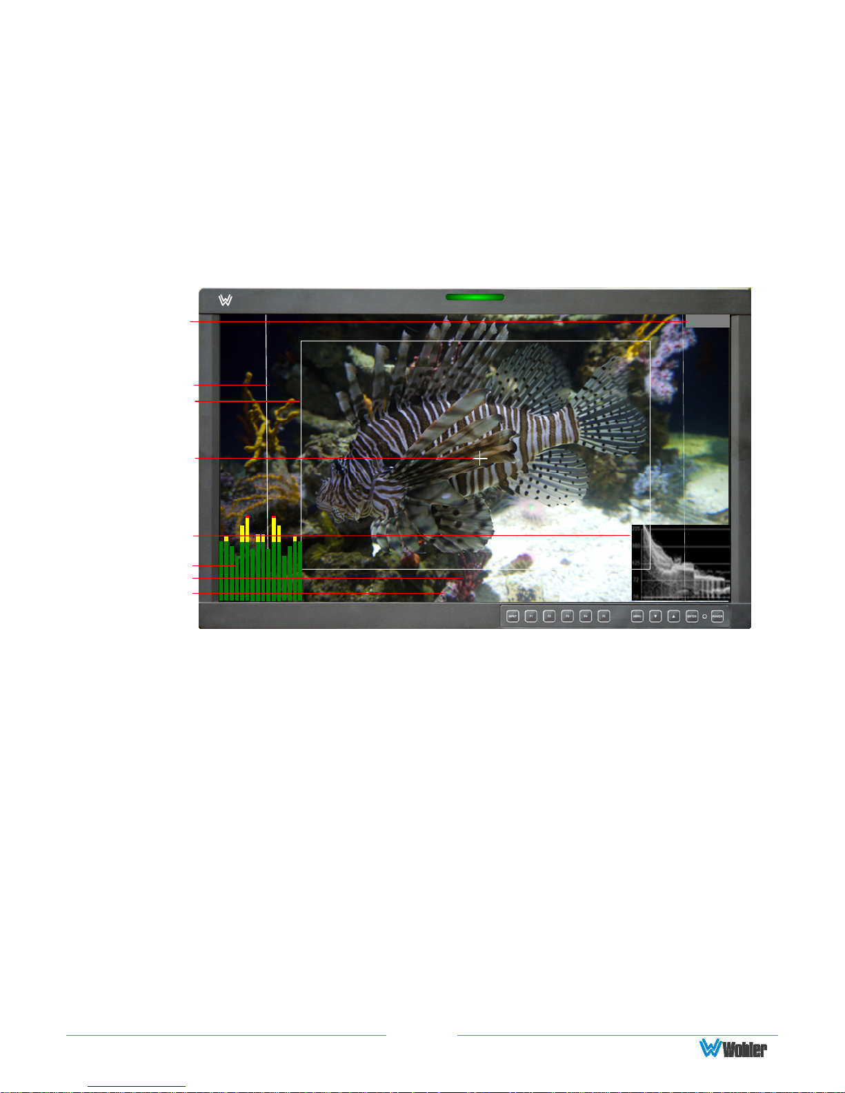
Figure 2-2: Display Features
Input Status
Area Marker
Safety Marker
Center Marker
Waveform / Vectorscope
Audio Level Meters
Timecode
IMD
1. Input Status: Displays the detected input and video parameters of the
signal: vertical active line count, (i)nterlaced or (p)rogressive, and
field/frame rate in Hz. This display is controlled be a setting in the Display
Menu. Refer to Table 2-9.
2. Area Marker: Used to mark an alternate aspect ratio area of the image. You
can set whether to display it, the brightness, and the matte mode in the
Marker Menu. Refer to Table 2-7.
3. Safety Marker: This is used to mark a percentage area, inside of the image,
safe for titles to be located. You can set whether to display it, as well as its
display mode, in the Marker Menu. Refer to Table 2-7.
4. Center marker: Cross hairs are displayed in the center of the screen,
marking the center of the image. You can set whether to display them in the
Marker Menu. Refer to Table 2-7.
5. IMD: The IMD Menu provides settings to customize the IMD (In Monitor
Display) text area to show a static line of characters, numbers, and certain
symbols or to receive dynamic messages to be displayed. Refer to Table 2-
16.
6. Audio Level Meters: Levels for the audio channels are displayed on up to
sixteen bar graph meters as left/right pairs. The meters can appear in
various selectable positions on the screen. Refer to Table 2-8.
Wohler
--: --: --: --
HDM-215-3G
HDM-215-3G
SDI1
1080I59.94
Page
11
Important
:
By design, the supplied AC mains power cord will only plug into a
7. Timecode: The de-embedded timecode from the HD/SD-SDI source displays
on the lower part of the screen. The timecode setting is located in the Display
Menu. Refer to Table 2-9.
8. Waveform/Vectorscope: This can be displayed only for SDI signals. The
waveform and vector of the input signal display are configurable in the
Display Menu. Refer to Table 2-9.
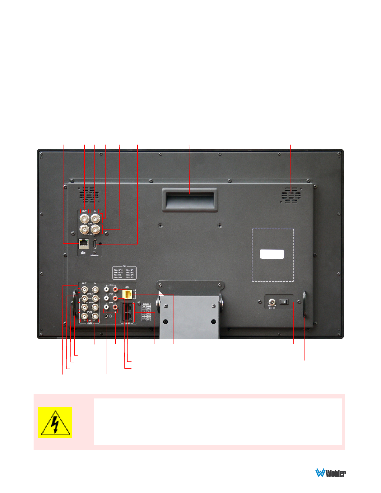
Rear Panel
Right Speaker
Ethernet
Out
In
SDI 1
SDI 2
Figure 2-3: Rear Panel Layout
HDMI In
Left SpeakerCarrying Handle
L/R
Audio
Out
Headphone
RS-485
In/Out
L/R Audio In 1
L/R Audio In 2
GPI
Line 1 CVBS
InOut
Line 2 Pr
Line 2 Pb/C
Line 2 CVBS/Y
three-prong grounded outlet for your safety. If the plug does not fit
into the outlet, contact an electrician to replace the obsolete outlet.
The symbol to the left warns of electric shock hazard inside or outside
the unit. Disconnect the power cord before removing access panels.
Page
12
12 VDC
Power
Connector
Power
Switch
Cable Ring

Important:
The monitor and power adapter have been tested as a combined
. Wohler Technologies cannot accept any responsibility for the
outcome in such cases.
apparatus to verify compliance with applicable safety and
electromagnetic compliance standards. Use of another power adapter
provided by the user may negate the compliance or not perform
properly
1. SDI 1 In: This input connector accepts 3G/HD/SD-SDI video signals. It is
compliant with SMPTE 424M, SMPTE 259M, SMPTE292M/ITU-R BT601. It can
be viewed using the SDI1 selection on the Input button menu.
2. SDI 1 Out: This connector provides a re-shaped and re-clocked duplicate of
the SDI 1 In signal. This connection is compliant with SMPTE 424M, SMPTE
259M, SMPTE292M/ITU-R BT601.
3. SDI 2 In: This is the second 3G/HD/SD-SDI video signal input. This
connection is compliant with SMPTE 424M, SMPTE 259M, SMPTE292M/ITU-R
BT601. It can be viewed using the SDI2 selection on the Input button menu.
4. SDI 2 Out: This connector provides a re-shaped and re-clocked duplicate of
the SDI 2 In signal. This connection is compliant with SMPTE 424M, SMPTE
259M, SMPTE292M/ITU-R BT601.
5. Line 1 In Video: This is the first input for an analog CVBS video signal. It
can be viewed using the LINE 1 selection on the Input button menu.
6. Line 1 Out Video: This is a pass through connection for the Line 1 In video
signal.
7. Line 2 In CVBS/Y: This is the second analog CVBS video input signal or the
luminance (Y) signal of Y/C or YPbPr. This input combined with the other Line
In 2 input signals can be viewed using the LINE 2 selection on the Input
button menu.
8. Line 2 Out CVBS/Y: This is a pass through connection for the Line 2 In
CVBS/Y video signal.
9. Line 2 In Pb/C: This is the chroma (C) signal of Y/C or YPbPr. This input
combined with the other Line In 2 input signals can be viewed using the
LINE 2 selection on the Input button menu.
10. Line 2 Out Pb/C: This is a pass through connection for the Line 2 In
Pb/C video signal.
11. Line In 2 Pr: This is red (Pr) component of YPbPr. This input combined with
the other Line In 2 input signals can be viewed using the LINE 2 selection on
the Input button menu.
12. Line 2 Out Pr: This is a pass through connection for the Line 2 In Pr video
signal.
13. HDMI In: This input supports HDMI and DVI signals. It uses an HDMI Type-
A connector. It can be viewed using the HDMI selection on the Input button
menu.
14. Audio In 1: A pair of analog audio inputs related to the Line 1 video signal
is provided on RCA jacks. They have a 47KΩ input impedance and will accept
Page
13

up to a 5dBu signal. These inputs are selected when the LINE 1 selection
button is pressed.
15. Audio In 2: A pair of analog audio inputs related to the Line 2 video signal
is provided on RCA jacks. They have a 47KΩ input impedance and will accept
up to a 5dBu signal. These inputs are selected when the LINE 2 selection
button is pressed.
16. Headphones: A standard 1/8" stereo headphone jack is provided. The
speakers will mute when a headphone is inserted into this jack.
17. Audio Out: A pair of analog outputs is provided on RCA jacks. They will
output the audio from the selected video source to be used with external
amplifiers and speakers if needed. They have a 500Ω output impedance and
will produce up to a 5dBu signal.
18. Power Connector: The supplied 100 to 240VAC to 12VDC power supply
plugs into this coax connector.
19. Power Switch: This switch removes all power from the product. Normally,
since this switch is on the rear panel, it is left in the 1 (On) position and the
front panel Power button is used to start and stop product operation.
20. Ethernet: The 10/100M Ethernet connector is used to connect with a
computer to modify the display settings remotely. CAT5 network cables are
recommended for medium distances. CAT6 twisted pair shielded cables are
recommended for longer distances.
21. GPI: This RJ45 jack controls the tally lights on the front panel. Refer to
Figure 2-5 below for the pinout and Table 2-2 for the terminal connections.
Either CAT5 or CAT6 cables may be used for this jack. The possible functions
for GPI contact closures are described in the GPI Menu shown in Table 2-15.
22. RS-485 In/Out: These RJ-45 jacks are used for dynamic Tally/IMD
controls. Two jacks are provided for in & out daisy chain arrangements. They
are wired identically. Refer to Figure 2-4 below for the pinout and to Table 23 for terminal connections. These connections are also used for system
software upgrades. Either CAT5 or CAT6 cables may be used for these jacks.
23. Right and Left Speakers: The audio monitoring speakers are positioned
on the rear panel. The volume of the speakers is controlled using the Quick
Menu. Refer to the Quick Menu section of this chapter.
24. Carrying Handle: A carrying handle is provided so that the monitor can be
securely carried from location to location.
25. Cable Rings: Rings are provided on the right and left of the rear panel to
be used for securing the connecting cables, if desired.
Page
14
 Loading...