

Wohler RMT-173-RM, RMT-173-TT User Manual

RMT-173 Series
• RMT-173-RM
• RMT-173-TT
Dual Input, LCD, Multi-Viewer Audio/
Video Monitors
User Guide
Part Number 821100, Revision A

© 2013 Wohler Technologies, Inc. All rights reserved.
This publication is protected by federal copyright law. No part of this publication may be
copied or distributed, stored in a retrieval system, or translated into any human or computer
language in any form or by any means electronic, mechanical, manual, magnetic, or otherwise,
or disclosed to third parties without the express written permission of Wohler Technologies.
Reproduction
Licensed users and authorized distributors of Wohler Technologies, Inc. products may copy
this document for use with Wohler Technologies., Inc. products provided that the copyright
notice above is included in all reproductions.
Customer Support
Wohler Technologies, Inc.
31055 Huntwood Avenue
Hayward, CA 94544
www.wohler.com
Phone: 510-870-0810
FAX: 510-870-0811
US Toll Free: 1-888-596-4537
(1-888-5-WOHLER)
Web: www.wohler.com
Sales: sales@wohler.com
Support: support@wohler.com
Disclaimers
Even though Wohler Technologies, Inc. has tested its equipment and software, and reviewed
the documentation, Wohler Technologies, Inc. makes no warranty or representation, either
express or implied, with respect to software, documentation, their quality, performance,
merchantability, or fitness for a particular purpose.
Wohler Technologies, Inc. reserves the right to change or improve our products at any time and
without notice.
In no event will Wohler Technologies, Inc. be liable for direct, indirect, special, incidental, or
consequential damages resulting from any defect in the hardware, software, or its
documentation, even if advised of the possibility of such damages.
Some states do not allow the exclusion or limitation for incidental or consequential damages, so
the above exclusion or limitation may not apply to you.
Printing
This document is intended to be printed on a duplex printer, such that the copy appears on
both sides of each page. This ensures that all new chapters start on a right-facing page.
This document looks best when printed on a color printer since some images may be indistinct
when printed on a black and white printer.
Last Update
October 17, 2013
8 2110 0 : RM T- 1 7 3 Ser i e s User G u i d e
ii
© 201 3 Wo h l e r Te c h n o logie s , Inc . A l l ri g h t s re s e r v ed.

Introduction
Overview
The RMT-173 Series dual input, LCD video monitors are highperformance, professional LCD monitors that support advanced 12-bit
digital processing technology with 3D comb filter and de-interlace,
accurate scaling engine, GAMMA correction and color temperature
adjustments to achieve the best possible image display.
The RMT-173 Series supports 2-channel 3G/HD/SD-SDI, Y/C,
component, and CVBS signal inputs as well as a single HDMI signal
input. Each model can simultaneously display two signal inputs, with
three display modes including one full screen display, Picture-InPicture (PIP) displays or two Picture-By-Picture (PBP) uniform size
screen displays.
RMT-173 Series
Topics
Topics Page
Introduction 1
Safety 2
Installation Recommendations 3
Unpacking and Installation 4
Features 7
Front Panel Features 8
Rear Panel Features 11
Using the Menu System 15
Specifications 29
Technical Function Overview 32
8 2110 0 : RM T- 1 7 3 Ser i e s Use r G u i d e
© 2 0 1 3 Wohl e r Techn o l o gies, I n c. A l l rig h t s re ser v e d .
1

RM T - 1 73 S e r ies
Saf e t y
Safety
Important Safety Instructions
1. Read, keep, and follow all of these instructions; heed all warnings.
2. Do not use this equipment near water, rain or moisture.
3. Use only a dry cloth to clean the equipment.
4. Do not install near any heat source such as a radiator, heat register,
amplifier, or stove.
5. Do not attempt to plug the unit into a two-blade outlet (with only
two prongs of equal width).
IMPORTANT:
By design, these monitors will only plug into a three-prong outlet for
your safety. If the plug does not fit into your outlet, contact an
electrician to replace the obsolete outlet.
6. Protect the power cord from being walked on or pinched,
particularly at plug’s source on the equipment and at the socket.
7. Use only the attachments/accessories specified by the
manufacturer.
8. Unplug the equipment during lightning storms or when unused
for long periods of time.
9. Use of a cart is neither recommended nor approved by Wohler.
10. Refer all servicing to qualified service personnel. Servicing will be
required under all of the following conditions:
• The equipment has been damaged in any way, such as when
the power-supply cord or plug is damaged.
• Objects have fallen onto the equipment; or the equipment has
been exposed to rain or moisture, or liquid has been spilled
onto the equipment.
• The equipment does not operate normally.
• The equipment has been dropped.
8 2110 0 : RM T- 1 7 3 Ser i e s User G u i d e
2
© 201 3 Wo h l e r Te c h n o logie s , Inc . A l l ri g h t s re s e r v ed.
Safety Symbols
RMT-173 Series
In s t a lla t i o n R e c om m e n da t i o n s
WARNING:
The symbol to the left warns of electric shock hazard inside the unit.
Disconnect the power cord before removing access panels when
installing upgrades. Only qualified service personnel are to operate the
equipment with covers removed, and are to exercise caution to avoid
personal injury.
Installation Recommendations
Heat Dissipation
The ambient temperature around the unit should not exceed 40°
Celsius (104° Fahrenheit). Allow plenty of space around the unit for air
circulation.
Mounting/Bracing
A table top (-TT) stand or rack mount (-RM) kit may be provided. A
standard VESA 100 mounting hole pattern is provided on the back of
the unit for use with other mounts (not supplied).
Refer to Mounting on page 5 for instructions on attaching the desktop
stand.
Connections and Cable Recommendations
We recommend that you limit the length of the cables that you use for
feeding HD-SDI signals sources to the HD-SDI inputs of the RMT-173
Series units and that you use a Belden 1694A cable (or equivalent). The
HD-SDI inputs (IN1 and IN2) can be up to 150 meters (492 feet) in
length for 1.5 Gbps (HD), more for 270 Mbps (SD) and less for 3Gbps.
8 2110 0 : RM T- 1 7 3 Ser i e s Use r G u i d e
© 20 1 3 Wo h l e r Tec h n o l ogies , Inc. A l l rig h t s re serv e d .
3

RM T - 1 73 S e r ies
Un p a c k in g a n d I n sta l l a tio n
Note:
HDMI 1.3 or 1.4 cable lengths of 2m (6 feet) are guaranteed
to work well. Four meters (12 feet) lengths of high quality
cable should work well enough, but is not guaranteed for all
situations. Longer HDMI cables often degrade signal
quality. Active extender transmitter/receiver pairs can be
used to cover long distances.
Electrical Interference
Be careful to properly terminate/ground signals and avoid
mismatched cable types and other similar causes of undesired
reflections in digital signal systems. If severe enough, such reflections
can result in corruption of the digital data stream. As with any audio
equipment, maximum immunity from electrical interference requires
the use of shielded cable. The internal circuitry ground is connected to
the chassis.
Power
The unit comes with a standard 12 VDC/5 A external power adapter
and connects an A/C mains power source (65W, 100 to 240 VAC, 50/
60Hz) through the IEC connector provided on the power adapter.
When the mains plug or appliance coupler is used as the disconnect
device, the disconnect device connection should remain accessible to be
operable.
Unpacking and Installation
Contents
While unpacking the components, verify that none of the components
are damaged. The selected stand or mounting kit comes in a separate
box.
Also verify that the box contains all of the following:
• Monitor
8 2110 0 : RM T- 1 7 3 Ser i e s User G u i d e
4
© 201 3 Wo h l e r Te c h n o logie s , Inc . A l l ri g h t s re s e r v ed.
Mounting
RMT-173 Series
Un p a c kin g a nd I n sta l l a tio n
• Adapter (12 VDC)
• Power cord
• User guide CDROM
• Warranty card
The RMT-173 Series monitors come standard with either a table top
base (RMT-173-TT) or rack ears (RMT-173-RM). A standard VESA 100
pattern accommodates other user-supplied mountings, such as for
walls.
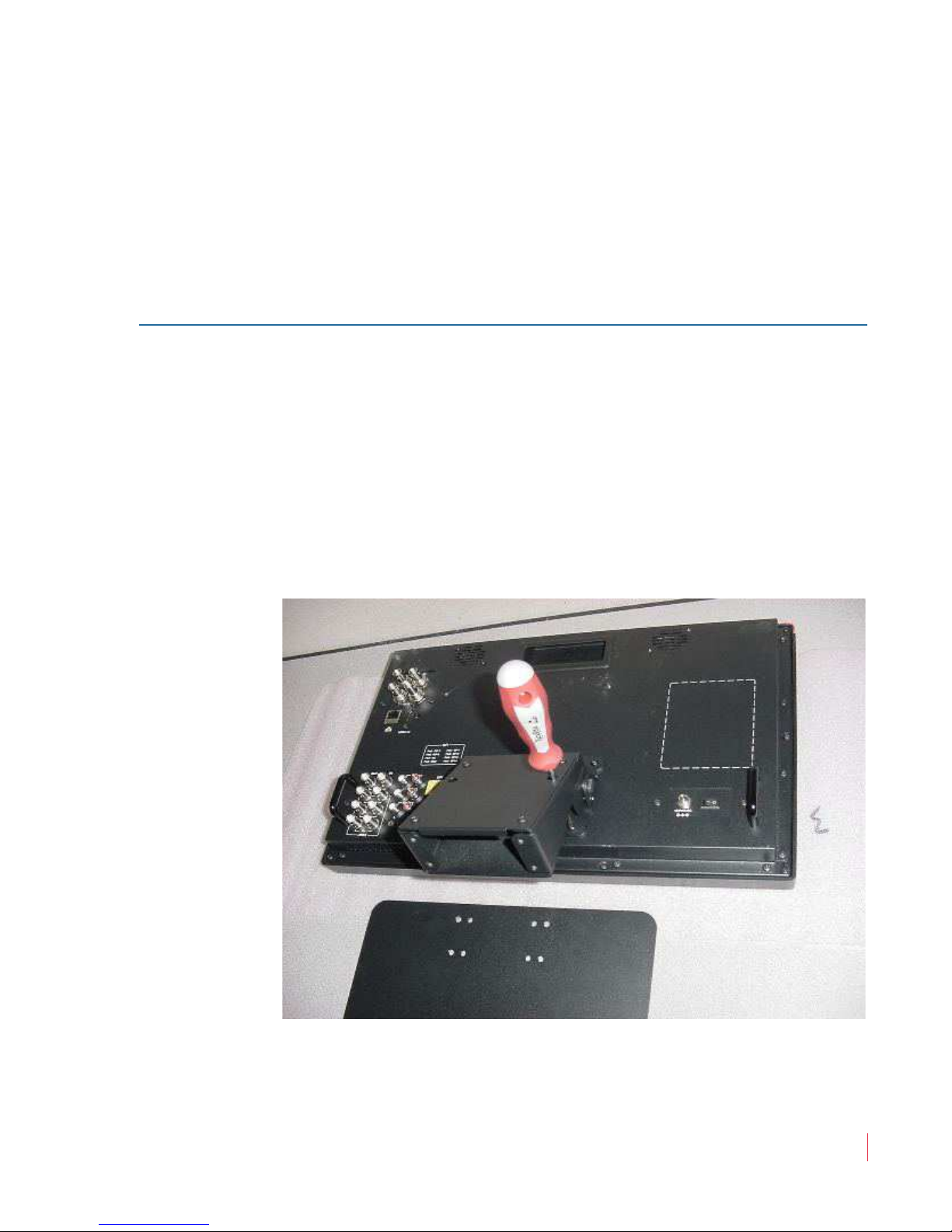
To install the table-top base, refer to Figure 1–1 and the instructions that
follow. Refer to the instructions included with other mounts when
used.
Figure 1–1 RMT-173-RM Bracket Installation
8 2110 0 : RM T- 1 7 3 Ser i e s Use r G u i d e
© 20 1 3 Wo h l e r Tec h n o l ogies , Inc. A l l rig h t s re serv e d .
5
RM T - 1 73 S e r ies
Un p a c k in g a n d I n sta l l a tio n
1. Place the monitor face down on a smooth surface and, as shown in
Figure 1–1, use a screwdriver and the supplied round head screws
to fasten the bracket to the back of the monitor.
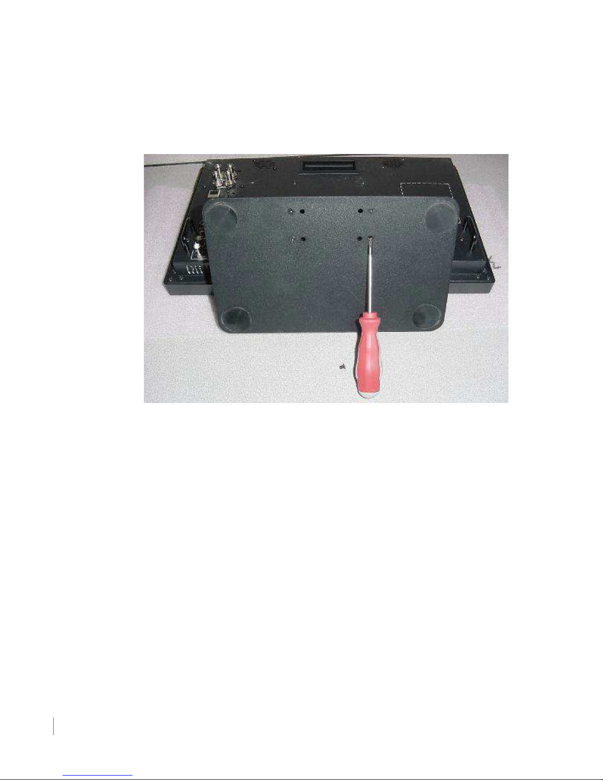
Figure 1–2 RMT-173-RM Base Installation
2. Next, again using a screwdriver, attach the base to the bracket,
with the supplied flat head screws, as shown in Figure 1–2.
3. Place the monitor upright on a solid static-free surface.
4. Connect the signal inputs to the rear panel.
5. Connect the power cord to the rear panel of the monitor and to
mains power.
6. Set the Power switch on the rear panel of the monitor to On (1).
8 2110 0 : RM T- 1 7 3 Ser i e s User G u i d e
6
© 201 3 Wo h l e r Te c h n o logie s , Inc . A l l ri g h t s re s e r v ed.

Features
The RMT-173 Series monitors provide the following features:
• Multi-format analog and digital audio signals
• Adjustment of the parameters for each channel
• High-quality waveform and/or vector monitoring
• Embedded SDI or stereo analog audio through speakers or
• Audio bar graph meters, up to sixteen
• Stereo analog audio line output of selected channel
• Area, safety, and center markers
RMT-173 Series
F e a t u r e s
headphones
• Closed captions for CVBS
• Pre-set or user-adjustable color temperature per channel
• Time code for SD/HD-SDI in ANC-packet form and D-VITC for
SD-SDI
• Dynamic OSD/IMD tally
8 2110 0 : RM T- 1 7 3 Ser i e s Use r G u i d e
© 20 1 3 Wo h l e r Tec h n o l ogies , Inc. A l l rig h t s re serv e d .
7
RM T - 1 73 S e r ies
Buttons
Status - Main
Audio Level Meters
Vertical (Bot Left)
LED Tally
Status - Sub
Fro n t Pa n e l Fea t u r e s
Front Panel Features
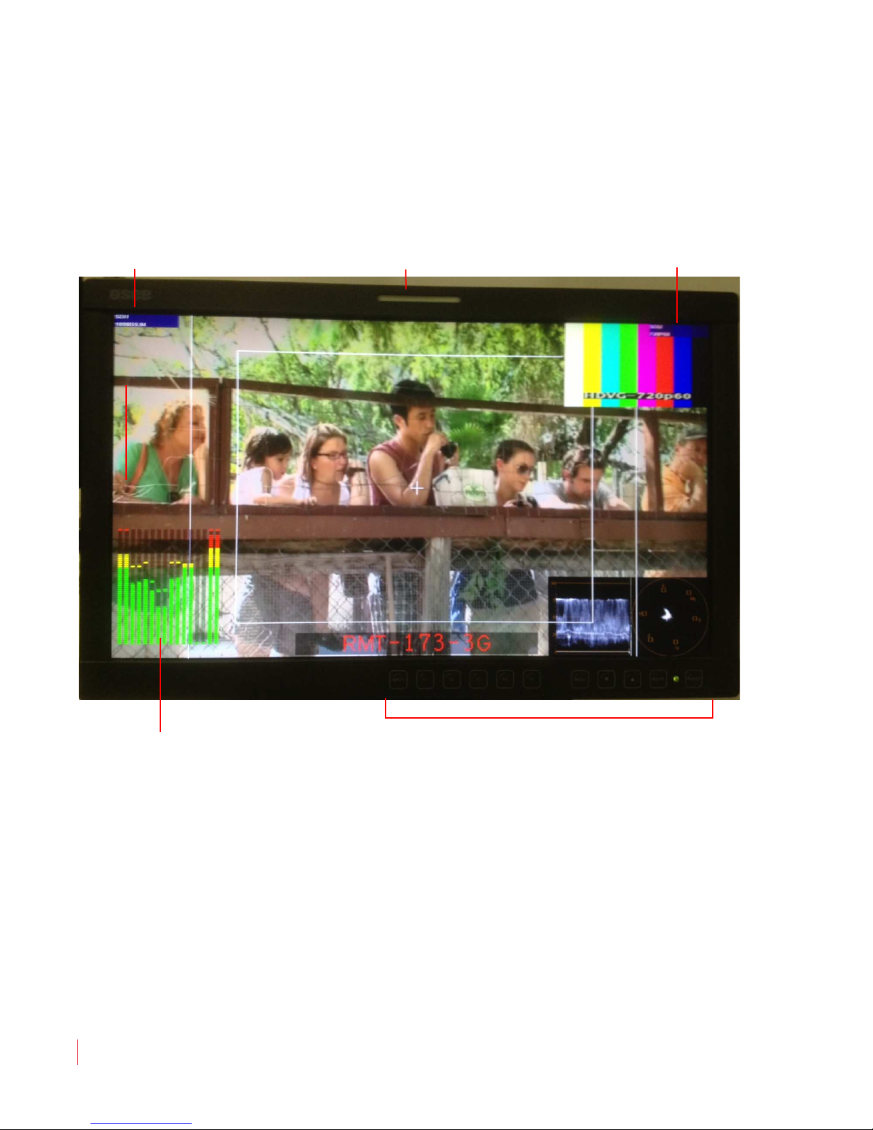
The following feature descriptions refer to Figure 1–3 below.
Figure 1–3 RMT-173 Front Panel (PIP Layout)
• Status: The status is displayed in the upper left corner for the main
window and in the upper right corner for the sub-window. It
includes the input channel number and signal format. Operation is
defined in the DISPLAY menu.
• Level Meters: Displays up to 16 channels, in horizontal or vertical
orientation. Define the meters setup in the AUDIO SOURCE and
METER DISPLAY menu options.
8 2110 0 : RM T- 1 7 3 Ser i e s User G u i d e
8
© 201 3 Wo h l e r Te c h n o logie s , Inc . A l l ri g h t s re s e r v ed.

RMT-173 Series
Fro n t Pa n e l F ea t u r e s
• IMD: The 16 characters of the in-monitor display (IMD) can be
displayed in red, green, yellow, or white. OSD CONFIG IMD
DISPLAY, IMD COLOR, and IMD CHAR define the static operation.
The IMD menu defines the dynamic IMD and OSD tally operations.
• Timecode: The display format for the timecode is HH: MM: SS: FF.
In the event no timecode is available, the monitor will display
--:--:--:--. Time code is currently available for SD/HD-SDI ANCpacketized and D-VITC for SD-SDI.
• Input: Pressing this button displays the Source menu. Further
presses cycle through available main video inputs. Alternately the
Up/Dn keys can be used.
• F1 through F5: These buttons serve as programmable hot keys.
Pressing a Function key displays the Function menu. Pressing the
key again toggles the state of that function. Refer to the Function
Key Menu on page 25 for details.
• Menu: Pressing this button displays the on-screen display (OSD)
Menu. Press MENU again to revert one menu level or exit out of
MENU mode.
• Up and Down: After pressing the MENU button, press Up or
Down to move within submenus.
• ENTER: After pressing the MENU button, pressing this button
selects the current menu or menu option. Changes are previewed,
but not saved, until you press the ENTER button again.
When the OSD Menu is not displayed, you can press the ENTER
button to quickly adjust the following parameters.
• VOLUME: Adjusts the volume from 0 to 30.
• BRIGHTNESS: Adjusts the video brightness from 0 to 100,
where 50 is the typical value.
• CONTRAST: Adjusts the image contrast from 0 to 100, where
50 is the typical value.
• CHROMA: Adjusts the color saturation from 0 to 100, where
50 is the typical value.
• Power LED: Lights red in standby mode and green when on. When
no main input signal is present, it blinks green.
• POWER (front): Toggles the monitor to on or standby mode.
8 2110 0 : RM T- 1 7 3 Ser i e s Use r G u i d e
© 20 1 3 Wo h l e r Tec h n o l ogies , Inc. A l l rig h t s re serv e d .
9
 Loading...