

Page 1

MPEG-3270 & MPEG-4290
3RU & 4RU Dual-Screen, MPEG, ASI,
3G/HD-SDI, and HDMI Video Monitor
User Guide
Part Number 821068, Revision A
Page 2

© 2013 Wohler Technologies, Inc. All rights reserved.
This publication is protected by federal copyright law. No part of this publication may be
copied or distributed, stored in a retrieval system, or translated into any human or computer
language in any form or by any means electronic, mechanical, manual, magnetic, or otherwise,
or disclosed to third parties without the express written permission of Wohler Technologies.
Reproduction
Licensed users and authorized distributors of Wohler Technologies, Inc. products may copy
this document for use with Wohler Technologies., Inc. products provided that the copyright
notice above is included in all reproductions.
Customer Support
Wohler Technologies, Inc.
31055 Huntwood Avenue
Hayward, CA 94544
www.wohler.com
Phone: 510-870-0810
FAX: 510-870-0811
US Toll Free: 1-888-596-4537
(1-888-5-WOHLER)
Web: www.wohler.com
Sales: [email protected]
Support: [email protected]
Disclaimers
Even though Wohler Technologies, Inc. has tested its equipment and software, and reviewed
the documentation, Wohler Technologies, Inc makes no warranty or representation, either
express or implied, with respect to software, documentation, their quality, performance,
merchantability, or fitness for a particular purpose.
In no event will Wohler Technologies, Inc. be liable for direct, indirect, special, incidental, or
consequential damages resulting from any defect in the hardware, software, or its
documentation, even if advised of the possibility of such damages.
Some states do not allow the exclusion or limitation for incidental or consequential damages, so
the above exclusion or limitation may not apply to you.
Printing
This document is intended to be printed on a duplex printer, such that the copy appears on
both sides of each page. This ensures that all new chapters start on a right-facing page.
This document looks best when printed on a color printer since some images may be indistinct
when printed on a black and white printer.
Other Technologies and Products
Dolby is a registered trademark of Dolby Laboratories, Inc.
Last Update
October 3, 2013
8 21 0 6 8 : MPE G - 3 2 70 & 4 2 9 0 U ser G u i de
ii
© 2 0 1 3 W o h l e r Te ch n o l o gie s, I n c . All r i g ht s res e r v e d .
Page 3

Table of Contents
Chapter 1. Installation . . . . . . . . . . . . . . . . . . . . . . . . . . . . 1
Introduction ...................................................................1
Overview..................................................................1
Topics ......................................................................1
Safety......................................................................2
Important Safety Instructions .....................................2
Safety Symbols .........................................................3
Installation Recommendations...........................................3
Mounting..................................................................3
Heat Dissipation ........................................................3
DC Power .................................................................4
On-Screen Display Features..............................................4
Front Panel.....................................................................5
Rear Panel Connectors ...................................................10
Chapter 2. Quick Start. . . . . . . . . . . . . . . . . . . . . . . . . . . . 13
Introduction ................................................................. 13
Overview................................................................ 13
Topics ....................................................................13
Unpacking ....................................................................14
Packing List ............................................................ 14
Unpacking and Powering for the First Time.................. 14
Setting up Inputs ..........................................................15
Monitoring a 3G/HD-SDI Signal ................................. 15
Monitoring an ASI Stream......................................... 16
Monitoring an Ethernet Stream..................................18
Monitoring an HDMI Signal .......................................19
© 2 0 1 3 W o h l e r Techn o l o g i es , I n c . A ll r i g h t s re se r v e d .
8 21 0 6 8 : M PE G - 3 2 7 0 & 42 9 0 U se r Gu i d e
iii
Page 4

Chapter 3. Operation . . . . . . . . . . . . . . . . . . . . . . . . . . . . 21
Introduction..................................................................21
Overview ................................................................21
Topics ....................................................................21
Initially Powering...........................................................22
Power Buttons...............................................................22
Input Buttons ...............................................................22
HDMI Button ...........................................................22
Ethernet .................................................................23
SDI/ASI .................................................................23
MPEG Screen Operation..................................................23
F1 - F6 Buttons .............................................................26
Adjust Settings .............................................................26
Screen Saver ................................................................27
Saving Your Options.......................................................28
Chapter 4. Configuration . . . . . . . . . . . . . . . . . . . . . . . . . 29
Introduction..................................................................29
Overview ................................................................29
Topics ....................................................................29
Using the Menu System..................................................30
Video Menu ..................................................................32
Audio Menu ..................................................................33
Marker Menu.................................................................35
UMD Options Menu ........................................................36
Functions Menu .............................................................37
GPI-In Menu .................................................................39
OSD Menu ....................................................................41
System Menu................................................................42
Preset Menu .................................................................43
Network Menu...............................................................45
Status Menu .................................................................47
8 21 0 6 8 : MPE G - 3 2 70 & 4 2 9 0 U ser G u i de
iv
© 2 0 1 3 W o h l e r Te ch n o l o gie s, I n c . All r i g ht s res e r v e d .
Page 5

MPEG Menu ..................................................................47
Chapter 5. Specifications . . . . . . . . . . . . . . . . . . . . . . . . . 49
Introduction ................................................................. 49
Overview................................................................ 49
Topics ....................................................................49
Specifications ...............................................................50
Compliance.............................................................53
Technical Functional Overview.........................................54
© 2 0 1 3 W o h l e r Techn o l o g i es , I n c . A ll r i g h t s re se r v e d .
8 21 0 6 8 : M PE G - 3 2 7 0 & 42 9 0 U se r Gu i d e
v
Page 6

8 21 0 6 8 : MPE G - 3 2 70 & 4 2 9 0 U ser G u i de
vi
© 2 0 1 3 W o h l e r Te ch n o l o gie s, I n c . All r i g ht s res e r v e d .
Page 7

Introduction
Overview
These 3RU and 4RU rack-mounted MPEG/Video/Audio monitors
arethe new benchmark in LCD monitors for broadcast and professional
video applications requiring support for both file-based and traditional
baseband sources. The monitor has 800 x 480 screen resolution, antiglare TFT screens, and fully digital signal processing. It supports
H.264/MPEG-4 Part 10, also known as AVC/H.264 or Advanced Video
Coding. It also supports H.262/MPEG-2 Part 2. These are decoded
from MPEG-2 TS (Transport Stream) containers in ASI or IP transport
interfaces. The TS container format can be either 188 bytes or 204 bytes.
Error correction bytes are not used. It does not decode encapsulated
transport streams in other formats, such as QuickTime (MPEG4/
H.264). The MPEG-3270 and MPEG-4290 also support 3G/HD-SDI and
HDMI. All video formats are scaled to native screen resolution in the
highest quality using precision scaling and gamma correction to
produce the best images available.
CHAPTER 1
Installation
This chapter contains detailed information on safety and installation
requirements. It also contains an overview of the front and back panel
controls, connectors, and screen features. To quickly unpack and set
up this unit for monitoring, please refer instead to Chapter 2: Quick
Start.
Topics
Topics Page
Introduction 1
Safety 2
© 2 0 1 3 Wo h l er Te c h n o l o gi e s , I n c. All r i g h t s re se r v e d .
821 0 6 8 : M PEG - 3 2 7 0 & 42 9 0 U se r Gu i d e
1
Page 8

Ch ap t er 1 In s t a ll a t i on
In t r o du c t i on
Topics Page
Installation Recommendations 3
On-Screen Display Features 4
Front Panel 5
Rear Panel Connectors 10
Safety
Important Safety Instructions
WARNING:
IMPORTANT:
Do not use this equipment near water, rain or moisture.
1. Read, keep, and follow all of these instructions; heed all warnings.
2. Use only a dry cloth to clean the equipment.
3. Do not block any ventilation openings. Install only in accordance
with the instructions in the section entitled, “Installation
Recommendations” on page 3.
4. Do not install near any heat source such as a radiator, heat register,
amplifier, or stove.
5. Do not expose the equipment to rain or moisture.
6. Do not attempt to plug the unit into a two-blade outlet (with only
two prongs of equal width).
By design, these audio/video monitors will only plug into a threeprong outlet for your safety. If the plug does not fit into your outlet,
contact an electrician to replace the obsolete outlet.
7. Protect the power cord from being walked on or pinched,
particularly at the plug’s source on the equipment and at the
socket.
8. Use only the attachments/accessories specified by the
manufacturer.
9. Refer all servicing to qualified service personnel. Servicing will be
required under all of the following conditions:
8 21 0 6 8 : MPE G - 3 2 70 & 4 2 9 0 U ser G u i de
2
© 2 0 1 3 W o h l e r Te ch n o l o gie s, I n c . All r i g ht s res e r v e d .
Page 9

• The equipment has been damaged in any way, such as when
• Objects have fallen onto the equipment; or the equipment has
• The equipment does not operate normally.
• The equipment has been dropped.
Safety Symbols
C h ap te r 1 Installation
In st a l l at i on R e c o m m en da t io ns
the power-supply cord or plug is damaged.
been exposed to rain or moisture, or liquid has been spilled
onto the equipment.
WARNING:
The symbol to the left warns of electric shock hazard inside the unit.
Disconnect the power cord before removing access panels when
installing upgrades. Only qualified service personnel are to operate the
equipment with covers removed, and are to exercise caution to avoid
personal injury or damage to the equipment from overheating.
Installation Recommendations
Mounting
These units are designed to install into a standard 19" rack mounted at
eye level for best visual observation of the monitor screen. Please
adhere to the following clearances to provide adequate ventilation:
Clearance Surface
24” Front
3” Rear
2” Sides
1.75” Top and Bottom
Heat Dissipation
These monitors contain two very quiet fans, so no special physical
mounting considerations are necessary regarding heat dissipation
except under adverse conditions, provided the ambient temperature
inside the mounting enclosure does not exceed 40°C (104°F).
Adjacent devices can be rack mounted (or stacked) in proximity
© 2 0 1 3 W o h l e r Techn o l o g i es , I n c . A ll r i g h t s re se r v e d .
8 21 0 6 8 : M PE G - 3 2 7 0 & 42 9 0 U se r Gu i d e
3
Page 10
Ch ap t er 1 In s t a ll a t i on
Markers:
Input Signal
Audio Level
Meters
Under
Monitor
Display
(UMD)
Area
Center
Safe Area
On - S c r e e n Di sp lay F e a t ur es
to the unit. If the temperature is above 104°F (40°C) allow an
additional 1RU 1.75” (44.45mm) space above and below the unit
for air circulation.
DC Power
The MPEG-3270 and MPEG-4290 require 24 VDC at 3 Amps. They
cannot be harmed by accidental reverse connection of power.
On-Screen Display Features
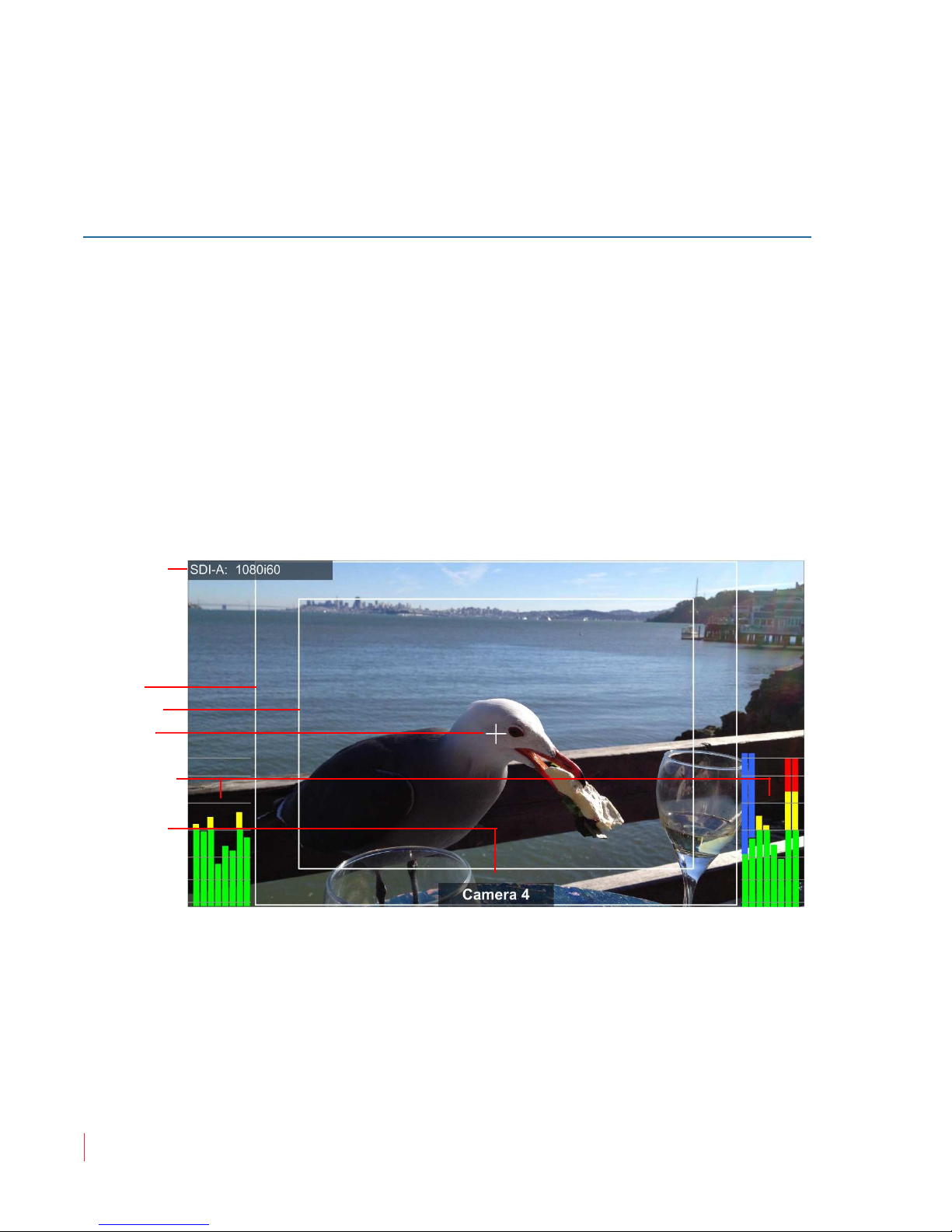
Some of the monitor display features (Figure 1–1) can be rearranged on
the screen as described in this section.
Figure 1–1 Display Features
• Input Signal: The detected input signal type is displayed.
controlled by the F1 button. Refer to F1 - F6 Buttons on page 26. The
Area marker can be shown in different aspect ratios using the
Marker Menu. Refer to the Marker Menu on page 35.
• Safe Area Marker: By default the appearance of the Safe Area
• Area Marker: By default the appearance of the Area Marker is
8 21 0 6 8 : MPE G - 3 2 70 & 4 2 9 0 U ser G u i de
4
© 2 0 1 3 W o h l e r Te ch n o l o gie s, I n c . All r i g ht s res e r v e d .
Marker is controlled by the F1 button. Refer to F1 - F6 Buttons on
Page 11

C h ap te r 1 Installation
Tally Lights
Headphone Jack
Speakers
USB Port
Fr o n t P an e l
page 26. Safe areas, ranging from 80% to 95%, are available from the
Marker Menu. Refer to the Marker Menu on page 35.
• Center Marker: By default the appearance of the Center Marker
is controlled by the F1 button. Refer to F1 - F6 Buttons on page 26.
• Audio Levels: By default the appearance of the Audio Level
Meters is controlled by the F2 button. Refer to F1 - F6 Buttons on
page 26. Levels for the selected audio channels can be displayed on
up to 16 meters evenly divided between the right and left sides of
the monitor screen.
• UMD: The UMD Options Menu on page 36 provides settings to
customize the UMD (Under Monitor Display) text area to show a
line of up to 16 characters.
Front Panel
The front panel feature descriptions below refer to Figure 1–2, Figure 1–
3, Figure 1–4 on page 7, and Figure 1–5 on page 8.
Figure 1–2 MPEG-3270 Front Panel Overview
• Tally Lights: These tri-color (red/green/amber) lights are
controlled through the Tally and GPI connector on the rear of the
panel. Note that the MPEG-3270 has two tally lights per screen, one
on the left and one on the right. These lights work in tandem. The
MPEG-4290 has only one tally light per screen.
© 2 0 1 3 W o h l e r Techn o l o g i es , I n c . A ll r i g h t s re se r v e d .
8 21 0 6 8 : M PE G - 3 2 7 0 & 42 9 0 U se r Gu i d e
5
Page 12

Ch ap t er 1 In s t a ll a t i on
Tally Lights
Headphone Jack
Speakers
USB Port
Fr o nt P an e l
• Speakers: Speakers on either side of the unit deliver sound from
the selected video input. Pressing or turning the Volume control of
a screen will automatically switch the audio in the speakers and
headphones to the audio from that screen’s selected audio channels.
• Headphone Jack (Mini 1/8”): This jack allows you to monitor
the assigned left/right stereo audio channels with stereo
headphones from this mini-stereo connector.
• USB: This port allows you to connect a flash drive to the MPEG-
3270 or MPEG 4290 to upgrade the firmware.
Figure 1–3 MPEG-4290 Front Panel Overview
8 21 0 6 8 : MPE G - 3 2 70 & 4 2 9 0 U ser G u i de
6
© 2 0 1 3 W o h l e r Te ch n o l o gie s, I n c . All r i g ht s res e r v e d .
Page 13
C h ap te r 1 Installation
Power
Adjust
Programmable Function
[F] Buttons
Input Source Selects
and Indicators
Menu/
Back
Volume, Mute, and
Menu Option Select
LCD Screen
Fr o n t P an e l
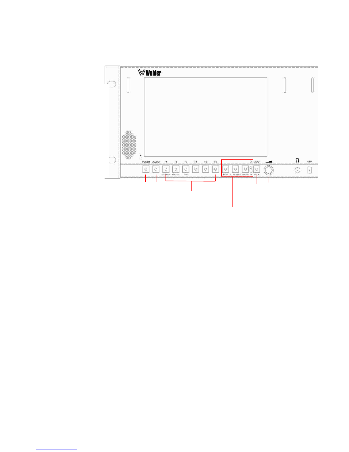
Figure 1–4 MPEG-3270 Screen Controls (One Set
Per Screen)
© 2 0 1 3 W o h l e r Techn o l o g i es , I n c . A ll r i g h t s re se r v e d .
8 21 0 6 8 : M PE G - 3 2 7 0 & 42 9 0 U se r Gu i d e
7
Page 14

Ch ap t er 1 In s t a ll a t i on
Power
Adjust
Programmable Function
[F] Buttons
Input Source Selects
and Indicators
Menu/
Back
Volume, Mute, and
Menu Option Select
LCD Screen
Fr o nt P an e l
Figure 1–5 MPEG-4290 Screen Controls (One Set
Per Screen)
• Power: Each of the two Power buttons turns its associated LCD
screen on and off. During startup, the power indicator blinks. When
the display is ready, it will stop blinking and remain on. Note that it
does take some time for each screen to power up. Refer to Power
Buttons on page 22 for more information.
• Adjust: This button, in conjunction with the Volume control,
allowing you to adjust a variety of video parameters. Refer to
Adjust Settings on page 26 for more information.
• F1 through F6: The F1-F6 buttons are programmable as hot keys
for parameter adjustments. Refer to the Functions Menu on page 37
for more information. The default function for each button is as
follows:
• F1 button is labeled MARKER. It will turn the Center, Area,
and Safety markers on or off. Refer to the Marker Menu on
page 35 to adjust the type and size of the markers.
• F2 button is labeled METER. It will turn the level meter
display on or off. Refer to the Audio Menu on page 33 to
control the scale and appearance of the meters.
8
8 21 0 6 8 : MPE G - 3 2 70 & 4 2 9 0 U ser G u i de
© 2 0 1 3 W o h l e r Te ch n o l o gie s, I n c . All r i g ht s res e r v e d .
Page 15

C h ap te r 1 Installation
Fr o n t P an e l
• F3 button is labeled IMD. It is planned in future software
releases that this function button will, by default, control the
appearance of IMD displays, however in the current software
release, this button is unassigned.
• F4 - F6 buttons are unassigned, but may be easily assigned to
control various functions. Refer to the Functions Menu on
page 37.
• HDMI: Pressing this button lights its indicator and selects the
HDMI input, deselecting the Ethernet and SDI/ASI inputs. Refer to
the Status Menu on page 47 for details on setting the HDMI audio
channels to monitor.
• ETHERNET: Pressing this button lights its indicator and selects the
Ethernet input connection as the MPEG source, deselecting the
HDMI and SDI/ASI inputs. Refer to MPEG Screen Operation on
page 23 for further details.
• SDI/ASI: Pressing this button lights its indicator and selects the
HDMI input, deselecting the Ethernet and HDMI inputs. It also
toggles between the SDI input sources for each screen: SDI-A (SDI
or ASI) and SDI-B (SDI or ASI). Selecting SDI-A is indicated by the
A LED; selecting SDI-B is indicated by the B LED. Since these
inputs can be more than one type, you must select the exact input
type from the System Menu. Refer to the System Menu on page 42
for details.
• Menu/Back: Pressing the Menu button displays the Main Menu.
Pressing it again returns you to the previous menu or to the Main
Screen from the Main Menu. Refer to Using the Menu System on
page 30 for more information.
• Volume/Enter: Rotating this knob when a menu is not displayed
increases or decreases the audio volume of the selected video
stream. Pressing or turning any Volume knob selects the audio of
that screen for monitoring and mutes or unmutes the audio. The
Volume knobs are also used to adjust options within the menu
system.
• LCD Screen: The LCD screens display the selected video and OSD
features. For MPEG video, they also display data and PID (packet
identifier) tables and other useful information.
© 2 0 1 3 W o h l e r Techn o l o g i es , I n c . A ll r i g h t s re se r v e d .
8 21 0 6 8 : M PE G - 3 2 7 0 & 42 9 0 U se r Gu i d e
9
Page 16
Ch ap t er 1 In s t a ll a t i on
Tally
& GPI
Cooling
Fan
3G/HD-SDI &
ASI In & Out
Power
HDMI In
Ethernet
RS-485
Re a r Pa n e l C on nec to rs
Rear Panel Connectors
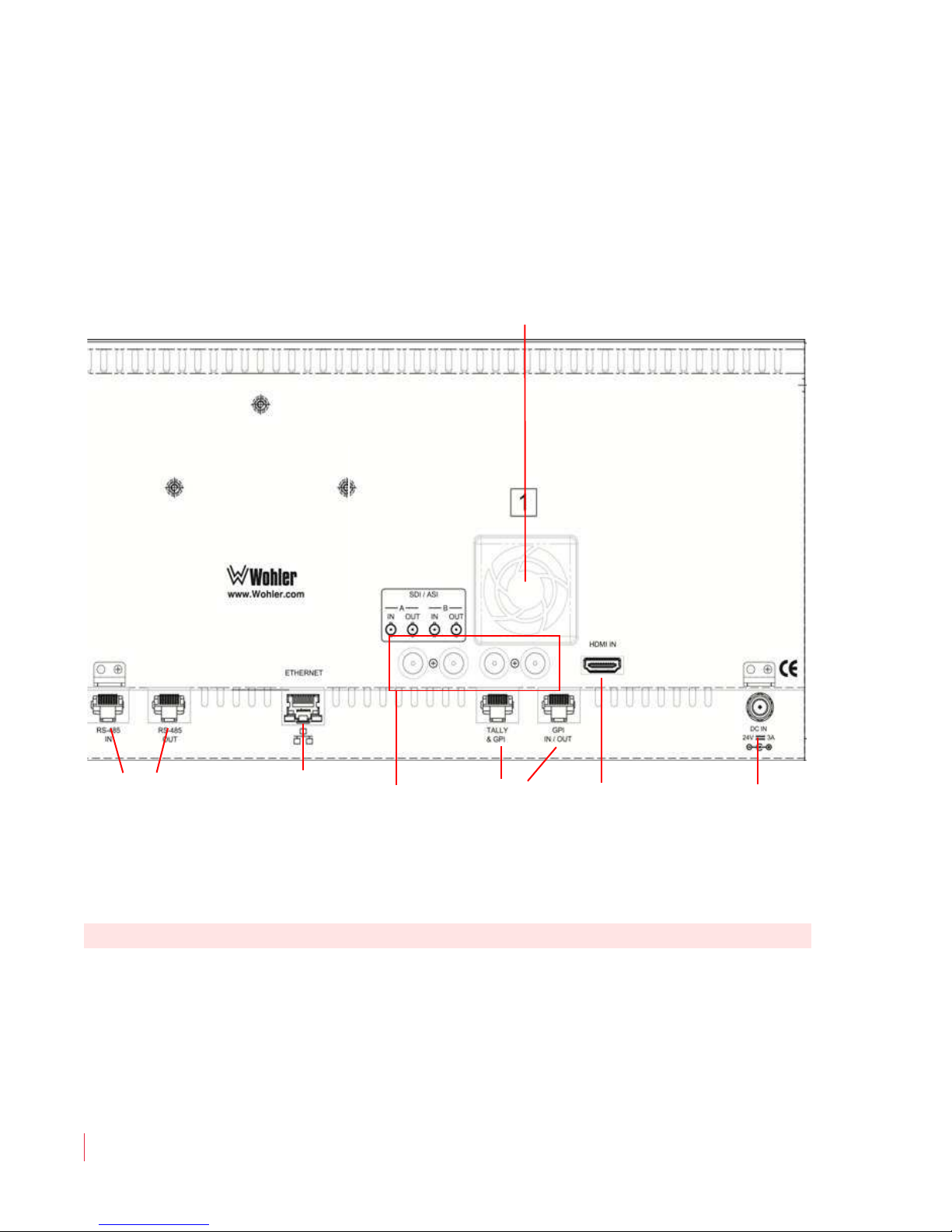
The rear panels of the MPEG-3270 and the MPEG-4290 are very similar,
except for rack unit height.
Figure 1–6 MPEG-3270 & MPEG-4290 Rear Panel
N o te :
• HDMI IN: This connector accepts an HDMI signal for display.
Select the HDMI input using the HDMI button on the front panel.
This input does not support encrypted sources.
• 3G/HD-SDI or ASI I/O (A & B, BNCs): These input connectors
accept standard 3G/HD-SDI or ASI MPEG video and audio. The
system regenerates the 3G/HD-SDI or ASI signals from each SDI/
ASI input before outputting them to these female BNC connectors.
Select these inputs using the SDI/ASI button on the front panel.
8 21 0 6 8 : MPE G - 3 2 70 & 4 2 9 0 U ser G u i de
10
© 2 0 1 3 W o h l e r Te ch n o l o gie s, I n c . All r i g ht s res e r v e d .
Page 17
C h ap te r 1 Installation
Re ar P a ne l C on ne c to rs
• RS-485 I/O (RJ-45): These two ports are used for UMD and
tally remote control.
• Ethernet (RJ-45): This connector is used for network
communications and MPEG input to each of the two screens.
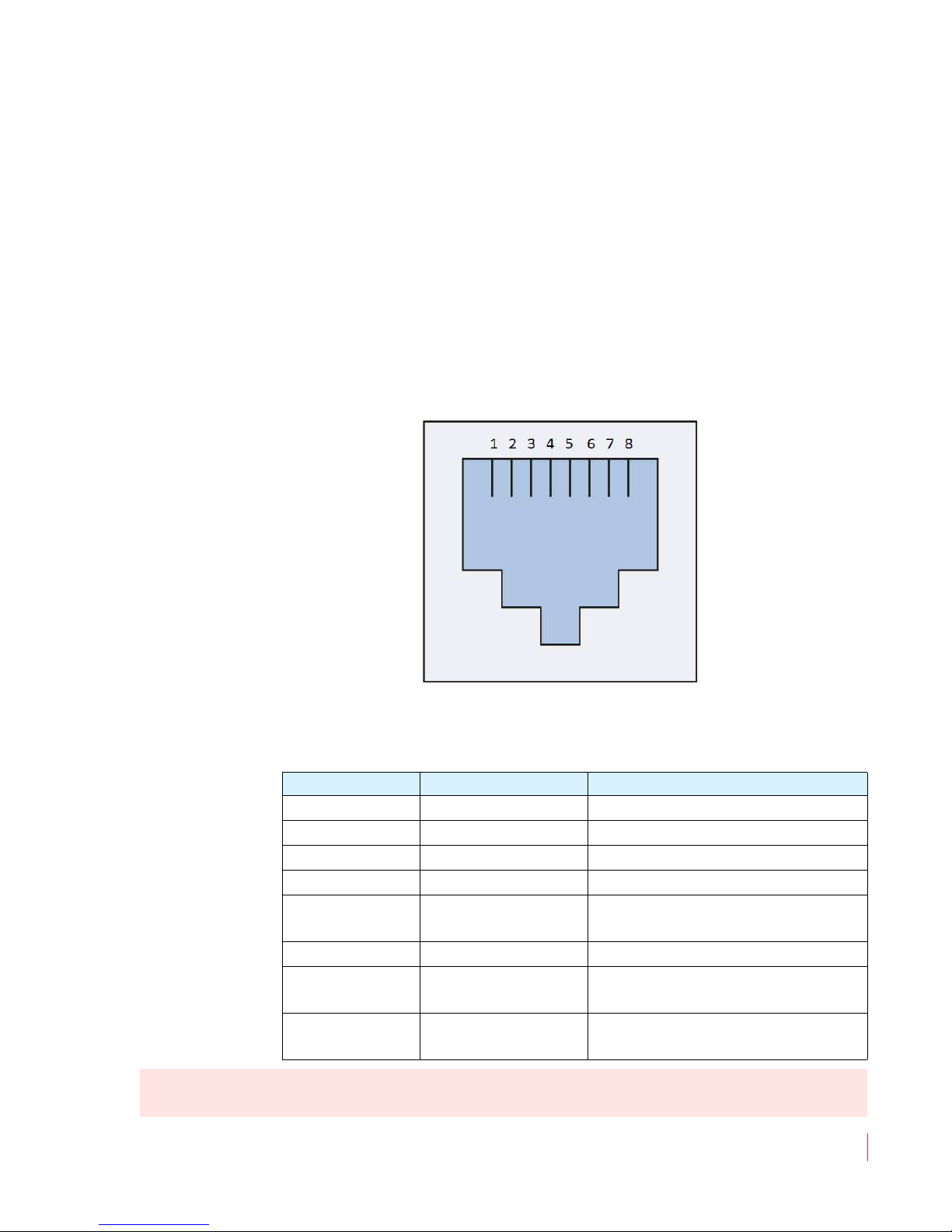
• Tally and GPI (RJ-45): This 8-pin connector controls the tally
lights on the front panel (2 pins) and allows remote control of the
unit through the other five available pins. Refer to Figure 1–7 and
Table 1–1 when making connections. Refer to the GPI-In Menu on
page 39 to set up operation.
Figure 1–7 Tally & GPI-I/O RJ-45 Connector
N o te :
Table 1–1 Tally & GPI RJ-45 Pinout
Pin Name Function
1 Tally Red Red Tally Signal
2 Tally Green Green Tally Signal
3 GPI-In 3 General Purpose Input 3
4 GPI-In 4 General Purpose Input 4
5 Gnd
Ground Return for signals on all
other pins
6 GPI-In 5 General Purpose Input 5
7 GPI-Out 7
8 GPI-Out 8
General Purpose Output 7
(future release)
General Purpose Output 8
(future release)
For a Yellow Tally, activate both the Red Tally and Green Tally
Signal inputs.
© 2 0 1 3 W o h l e r Techn o l o g i es , I n c . A ll r i g h t s re se r v e d .
8 21 0 6 8 : M PE G - 3 2 7 0 & 42 9 0 U se r Gu i d e
11
Page 18

Ch ap t er 1 In s t a ll a t i on
Re a r Pa n e l C on nec to rs
Im po r ta nt :
A signal input is defined to be a dry contact closure to ground for the
General Purpose Inputs as well as for the Tally LEDs. Do not
apply any voltages to these inputs.
• Cooling Fan: Please do not obstruct the airflow from these two
quiet fans.
• Power (DC): To provide power to the unit, attach the supplied 100
to 240VAC power supply, which will supply 24VDC to this
connector.
8 21 0 6 8 : MPE G - 3 2 70 & 4 2 9 0 U ser G u i de
12
© 2 0 1 3 W o h l e r Te ch n o l o gie s, I n c . All r i g ht s res e r v e d .
Page 19

Introduction
Overview
This pictorial guide will show you how to unpack and operate the
MPEG-3270 and MPEG-4270 for the first time.
Topics
CHAPTER 2
Quick Start
Topics Page
Introduction 13
Unpacking 14
Packing List 14
Unpacking and Powering for the First Time 14
Setting up Inputs 15
Monitoring a 3G/HD-SDI Signal 15
Monitoring an ASI Stream 16
Monitoring an Ethernet Stream 18
Monitoring an HDMI Signal 19
© 2 0 1 3 Wo h l er Te c h n o l o gi e s , I n c. All r i g h t s re se r v e d .
821 0 6 8 : M PEG - 3 2 7 0 & 42 9 0 U se r Gu i d e
13
Page 20

Ch ap t er 2 Qu ic k S ta r t
Un pa c k i ng
Unpacking
Packing List
1. One MPEG-3270 or MPEG-4290 Monitor
2. One 24V 3.0A External Power Supply
3. One IEC Standard Power Cord
4. One MPEG-3270 & MPEG-4290 User Guide (may be on CD-ROM)
Unpacking and Powering for the First Time
1. Take the MPEG-3270 or MPEG-4290 unit out of the box, and install
it into a rack or set it on a table during initial set up.
2. Unpack the external power supply and the IEC cord:
3. Plug the IEC power cord into the external power supply and then
plug the cord from the external power supply into the connector
on the back panel of the MPEG-3270 or MPEG-4290.
8 21 0 6 8 : MPE G - 3 2 70 & 4 2 9 0 U ser G u i de
14
© 2 0 1 3 W o h l e r Te ch n o l o gie s, I n c . All r i g ht s res e r v e d .
Page 21
Ch ap t er 2 Quick Start
Video Menu
Main Menu
Audio Menu
Marker Menu
Functions Menu
OSD Menu
System Menu
Preset Menu
System Status
GPI-In Menu
Network Menu
MPEG Status
UMD Options Menu
BNC Port B
System Menu
Backlight Interval
Panel LEDs
Calibration
Upgrade
None 5m 4h 8h 24h 48h
Restore
Upgrade
SDI ASI
Off On
BNC Port A SDI ASI
Se t t i ng up I np u ts
4. After connecting the power cords, you should see the A and B
indicators below each screen light up. Press the Power button
located at the left under each screen.
5. For 30 seconds, the Power indicators should flash. Then the
screens should show a progress bar, followed by some white
flashes and a splash screen showing the MPEG Series product line.
The start up process takes just over a minute. When the start up
process is complete, you should see the words, “SDI-A: No Sync”
at the upper left of the screen, assuming that no SDI signal is in fact
present.
6. Proceed to Monitoring a 3G/HD-SDI Signal on page 15,
Monitoring an ASI Stream on page 16, Monitoring an Ethernet
Stream on page 18, or Monitoring an HDMI Signal on page 19,
depending upon your monitoring needs.
Setting up Inputs
Monitoring a 3G/HD-SDI Signal
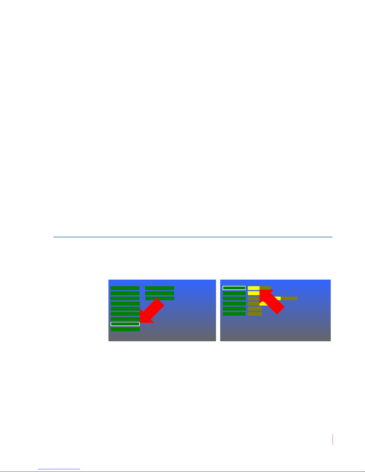
1. Press the Menu button to open the Main Menu. Rotate the
Volume knob to highlight the System Menu selection and press
it to enter the System Menu.
2. The SDI option should already be selected by default on BNC
Ports A & B. If it is not set this way, it can be changed by pressing
the Volume knob once and then turning it to move the selector on
BNC Port A to SDI. Press the Volume knob once to select SDI.
Use the same process for BNC Port B if you intend to connect an
SDI signal to SDI/ASI Input B. Finally press the Menu button
twice to exit.
© 2 0 1 3 W o h l e r Techn o l o g i es , I n c . A ll r i g h t s re se r v e d .
8 21 0 6 8 : M PE G - 3 2 7 0 & 42 9 0 U se r Gu i d e
15
Page 22
Ch ap t er 2 Qu ic k S ta r t
Video Menu
Main Menu
Audio Menu
Marker Menu
Functions Menu
OSD Menu
System Menu
Preset Menu
System Status
GPI-In Menu
Network Menu
MPEG Status
UMD Options Menu
BNC Port B
System Menu
Backlight Interval
Panel LEDs
Calibration
Upgrade
None 5m 4h 8h 24h 48h
Restore
Upgrade
SDI ASI
Off On
BNC Port A SDI ASI
Se t t i ng up I np u ts
3. If it is not connected already, connect the SDI source to SDI/ASI
A IN. Press the SDI/ASI button repeatedly to light the A LED.
SDI A: will be indicated in the upper left corner of the screen.
4. When the SDI signal is recognized, it will appear on the screen.
Monitoring an ASI Stream
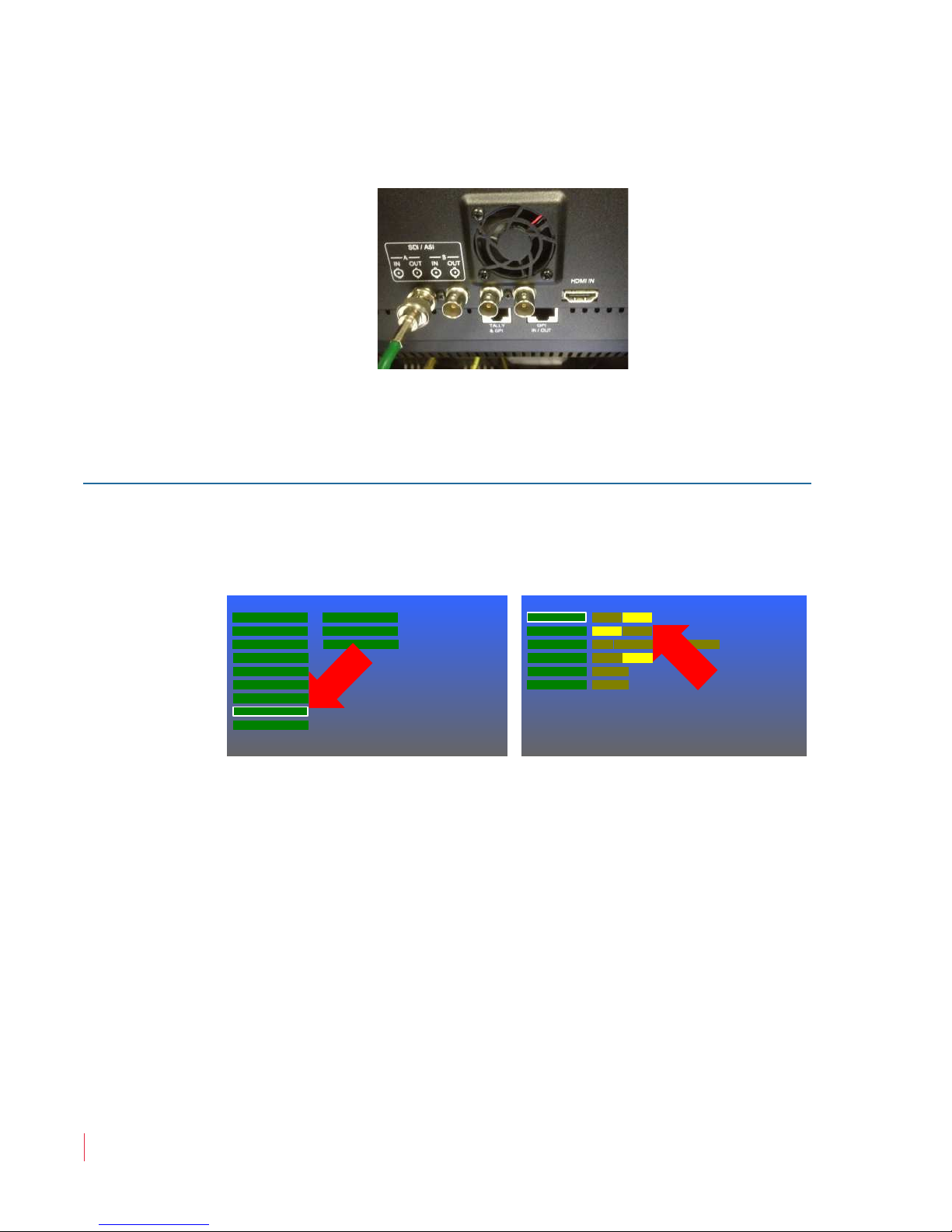
1. Press the Menu button to open the Main Menu. Rotate the
Volume knob to highlight the System Menu selection and press
it to enter the System Menu.
2. Turn the Volume knob to BNC Port A and press it once. Now
turn it again to select ASI. Press the Volume knob once to select
ASI. Use the same process for BNC Port B, if you will be
connecting a second ASI stream to SDI/ASI B IN. Finally press
the Menu button twice to exit.
16
8 21 0 6 8 : MPE G - 3 2 70 & 4 2 9 0 U ser G u i de
© 2 0 1 3 W o h l e r Te ch n o l o gie s, I n c . All r i g ht s res e r v e d .
Page 23
Ch ap t er 2 Quick Start
Video Menu
Main Menu
Audio Menu
Marker Menu
Functions Menu
OSD Menu
System Menu
Preset Menu
System Status
GPI-In Menu
Network Menu
MPEG Status
UMD Options Menu
PAT 00 CAT 01 NIT 16 SDT 17 EIT 18 TDT 20 SIT 31
0
31
256
4113
4352
20
TS
Ports
SDI-A ASI-B Eth UC Sync ASI TS
PID Type SI PIDs
4113
4097
4352
Video H.264 1280 720 119.88 1:1 0x27 HDMV
PCR
Audio AAC Layer 0 0 44.1kHz Stereo Open/Cpy noRA
PMT PID 256 PGM # 1 HDMV No Curr SIT
EXIT Only Vid-PID 4113 Aud-PID ----SEL and Exit
4113
4097
4352
Video H.264 1280 720 119.88 1:1 0x27 HDMV
PCR
Audio AAC Layer 0 0 44.1kHz Stereo Open/Cpy noRA
PMT PID 256 PGM # 1 HDMV No Curr SIT
SEL and Exit EXIT Only Vid-PID 4113 Aud-PID ----
Se t t i ng up I np u ts
3. If it is not connected already, connect the ASI source to SDI/ASI
A IN. Press the SDI/ASI button repeatedly to light the A LED.
ASI A: will be indicated in the upper left corner of the screen:
4. When you see ASI-A:TSSync in the upper left corner of the
screen, the signal has been recognized.
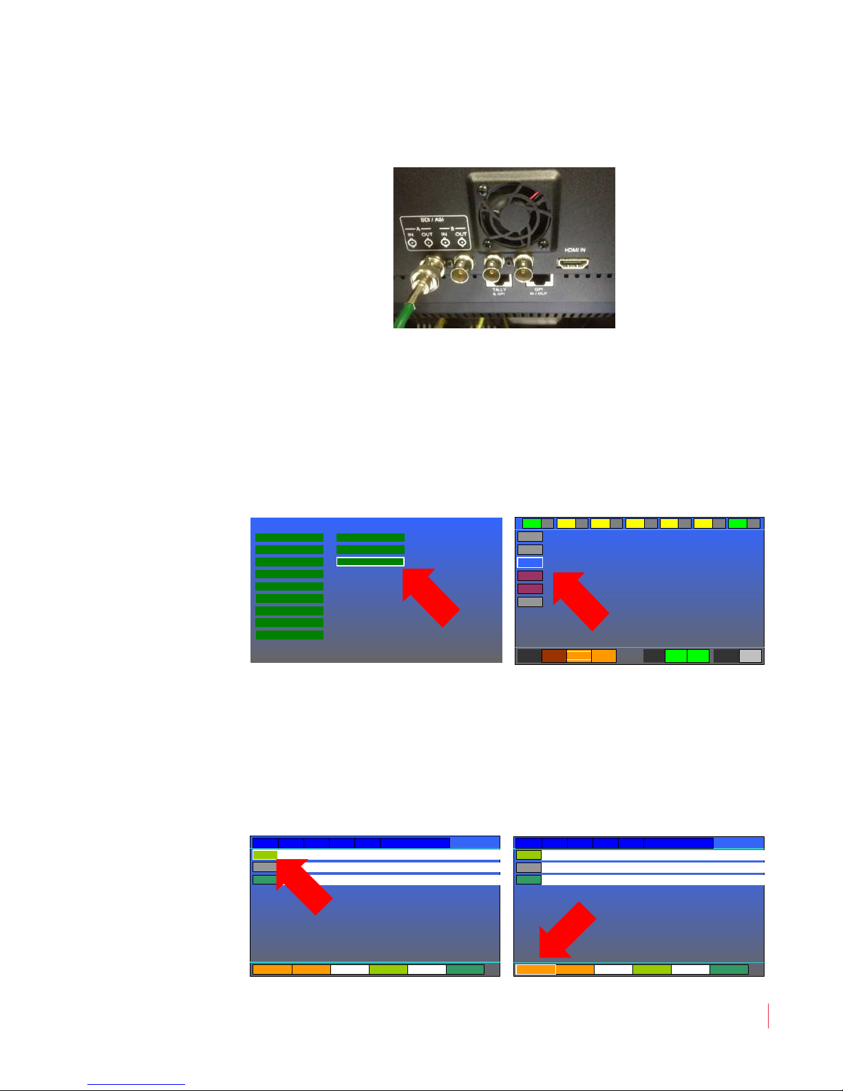
5. Press the Menu button to open the Main Menu. Rotate the
Volume knob to highlight the MPEG Screen selection and press
it to enter the MPEG Screen. In the MPEG Screen, turn the
Volume knob to highlight the PID to view and then press to
select.
6. This will proceed to the next menu where you can select the video
and audio PIDs. Turn the Volume knob to the video and audio
PIDs of interest and press to select them. When selected, they are
bright green. When you have selected the audio and video PIDs,
turn the Volume knob to highlight SEL and Exit at the lower left
of the screen. Press the Volume knob to return to the MPEG
Screen.
© 2 0 1 3 W o h l e r Techn o l o g i es , I n c . A ll r i g h t s re se r v e d .
8 21 0 6 8 : M PE G - 3 2 7 0 & 42 9 0 U se r Gu i d e
17
Page 24

Ch ap t er 2 Qu ic k S ta r t
Video Menu
Main Menu
Audio Menu
Marker Menu
Functions Menu
OSD Menu
System Menu
Preset Menu
System Status
GPI-In Menu
Network Menu
MPEG Status
UMD Options Menu
IP Mask
Network Menu
1234 SavePort Number
0 1 2 3 4 5 6 7 8 9
Clear Done
IP Address 192 1168 25 Save
255 255255 0 Save
Gateway Address 192 1168 16 Save
Se t t i ng up I np u ts
7. After a few seconds, the video should appear with the MPEG
Screen superimposed over it. If you prefer, you may remove the
superimposed MPEG Screen by pressing the Menu button twice.
N o te :
This input does not support encrypted sources.
Monitoring an Ethernet Stream
1. Connect the Ethernet plug to the ETHERNET jack on the back
panel of the MPEG-3270 or MPEG-4290. The one jack will serve all
four screens.
2. Press the Menu button to get to the Main Menu. Rotate the
Volume knob to highlight the Network Menu selection. Press
the Volume knob once to enter the Network Menu.
3. Rotate the Volume knob to each IP setting you need to change.
Press and turn the knob to make the changes. Press the Volume
knob to exit this menu into the Main Menu and then press it again
to exit the Main Menu.
4. Follow step 5 on page 17 through step 7 in the Monitoring an ASI
Stream section.
5. Press the Menu button twice to exit both the MPEG Screen and
18
8 21 0 6 8 : MPE G - 3 2 70 & 4 2 9 0 U ser G u i de
© 2 0 1 3 W o h l e r Te ch n o l o gie s, I n c . All r i g ht s res e r v e d .
the Main Menu. Press the Ethernet button. ETHUC: will appear
in the upper left corner of the screen. After a few seconds, the
video should appear. If you prefer, you may superimpose the
Page 25

Ch ap t er 2 Quick Start
Se t t i ng up I np u ts
MPEG Screen over the picture by pressing the Menu button,
followed by selecting the MPEG Screen with the Volume knob.
N o te :
This input does not support encrypted sources.
Monitoring an HDMI Signal
1. Connect the HDMI source plug to the HDMI IN jack on the back
panel for that screen as shown in Figure 1–6 on page 10.
2. Press the HDMI button. HDMI: will appear in the upper left
corner of the screen. After a few seconds, the video should appear.
N o te :
This input does not support encrypted sources.
© 2 0 1 3 W o h l e r Techn o l o g i es , I n c . A ll r i g h t s re se r v e d .
8 21 0 6 8 : M PE G - 3 2 7 0 & 42 9 0 U se r Gu i d e
19
Page 26

Ch ap t er 2 Qu ic k S ta r t
Se t t i ng up I np u ts
8 21 0 6 8 : MPE G - 3 2 70 & 4 2 9 0 U ser G u i de
20
© 2 0 1 3 W o h l e r Te ch n o l o gie s, I n c . All r i g ht s res e r v e d .
Page 27

Introduction
Overview
This chapter describes how to operate your MPEG-3270 or MPEG-4290.
Topics
CHAPTER 3
Operation
Topics Page
Introduction 21
Initially Powering 22
Power Buttons 22
Input Buttons 22
MPEG Screen Operation 23
F1 - F6 Buttons 26
Adjust Settings 26
Screen Saver 27
Saving Your Options 28
© 2 0 1 3 Wo h l er Te c h n o l o gi e s , I n c. All r i g h t s re se r v e d .
821 0 6 8 : M PEG - 3 2 7 0 & 42 9 0 U se r Gu i d e
21
Page 28

Ch ap t er 3 Op e r a ti on
In i ti a l l y Po w e r in g
Initially Powering
When the MPEG-3270 or MPEG-4290 is powered for the very first time,
it will look to the SDI-A input as its source. Thereafter, it will power up
with the input that was selected when it was last powered down.
Power Buttons
There is an individual Power button per screen and each may be
powered on or off individually. A single press of the Power button
starts the power on sequence, which will take approximately 65
seconds. During this time, the Power LED will blink. For the first 30
seconds, there will be no indication on the screen, but thereafter,
various progress bars and startup screens will appear. When the
Power LED is lit steadily, the power on sequence is complete.
To power a screen down, hold the Power button for 4 seconds. The
screen will turn off, as will the Power LED. The 4 second delay is
intended to prevent accidentally turning off a screen while it is in use.
Optionally, the Optionally, the Panel LEDs can be set so that they aren’t
lit when the MPEG-3270 or MPEG-4290 is in operation. This can be
useful in dark environments. Refer to the Panel LED option in the
System Menu on page 42.
Input Buttons
The three Input buttons allow quick selection of the various inputs.
HDMI Button
Pressing this button selects the HDMI connection on the back panel as
the signal source. When this is selected, the green LED within the
HDMI button glows. To learn how to set up the HDMI audio channels
to be monitored, refer to the Status Menu on page 47.
8 21 0 6 8 : MPE G - 3 2 70 & 4 2 9 0 U ser G u i de
22
© 2 0 1 3 W o h l e r Te ch n o l o gie s, I n c . All r i g ht s res e r v e d .
Page 29

Ethernet
SDI/ASI
Ch ap t er 3 Operation
MP EG S c re e n Op er a ti o n
Pressing this button will display UDP MPEG transport streams
received via the Ethernet connection on the back panel. When this is
selected, the green LED within the Ethernet button glows. To learn
how to set up the Ethernet connection to receive a stream, refer to the
Network Menu on page 45.
This button is used in conjunction with the BNC Port A and BNC Port
B selections in the System Menu on page 42. Pressing the SDI/ASI
button repeatedly selects order:
1. BNC Port A: This can be either a 3G/HD-SDI signal or an ASI
signal, as selected in the System Menu on page 42. When Port A is
selected, the A LED lights.
2. BNC Port B: This can be either a 3G/HD-SDI signal or an ASI
signal, as selected in the System Menu on page 42. When Port B is
selected, the B LED lights.
MPEG Screen Operation
The MPEG Screen is accessed through the Menu System, using the
MPEG Menu selection.
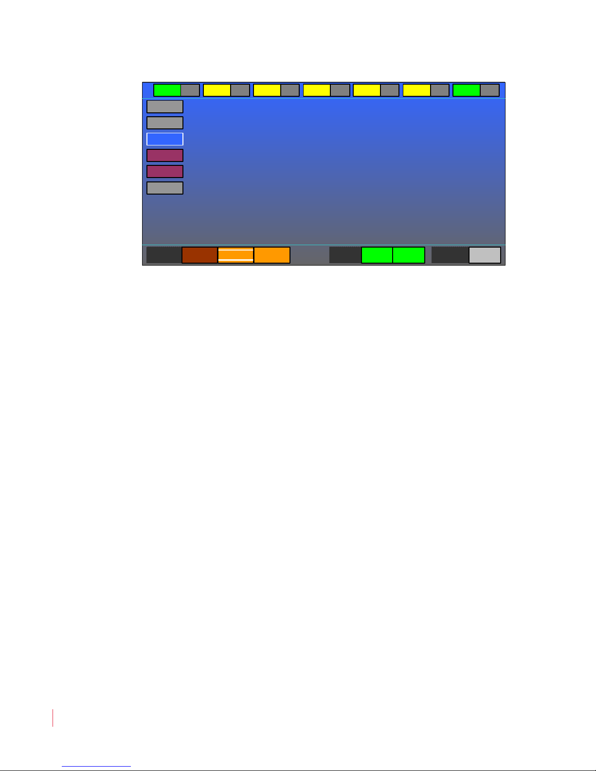
The MPEG Screen appears as follows:
© 2 0 1 3 W o h l e r Techn o l o g i es , I n c . A ll r i g h t s re se r v e d .
8 21 0 6 8 : M PE G - 3 2 7 0 & 42 9 0 U se r Gu i d e
23
Page 30
Ch ap t er 3 Op e r a ti on
PAT 00 CAT 01 NIT 16 SDT 17 EIT 18 TDT 20 SIT 31
0
31
256
4113
4352
20
TS
Ports
SDI-A ASI-B Eth UC Sync ASI TS
PID Type SI PIDs
MP EG S c re e n Op er a ti o n
Figure 3–1 MPEG Screen
This screen is used to monitor and make selections from the MPEG
transport stream. In the MPEG Screen, the Volume knob can be
rotated and pressed to access the following items:
1. PID Type: The PID Type (Program or Packet Identification
Type) offers a choice of SI (Service Information) PIDs or PMT
(Program Map Table) PIDs. Rotate the Volume knob to select SI
PIDs or PMT PIDs and then press. This will proceed to the SI
PIDs Screen (shown in Figure 3–2 on page 25) or the PMT PIDs
Screen (shown in Figure 3–3 on page 25), respectively.
2. TS Ports: These The TS Ports (Transport Stream Ports)
indicators show the selection you made using the SDI/ASI Input
button. The choices will vary according to what input signals are
present. The selected port will be bright orange and the other
choices will be dark.
3. Sync: These indicators will either be green for a good signal or
yellow if the expected sync signal isn’t found.
4. PID Selection: Rotate the Volume knob to select the PID of
interest and then press.
5. Status Indicators: The Status Indicators across the top of the
MPEG Screen offer a quick go/no go indication of the following
MPEG parameters: PAT (Program Association Table), CAT
(Conditional Access Table), NIT (Network Information Table),
SDT (Service Description Table), EIT (Event Information Table),
TDT (Time and Date Table), and SIT (Selection Information
Table). A green color indicates that there is no problem and a
8 21 0 6 8 : MPE G - 3 2 70 & 4 2 9 0 U ser G u i de
24
© 2 0 1 3 W o h l e r Te ch n o l o gie s, I n c . All r i g ht s res e r v e d .
Page 31
Ch ap t er 3 Operation
Service Svc Dest Svc Type
No Curr SIT
SIT 31 0x7f
Push to Exit
PrgNum
0
4113
4097
4352
Video H.264 1280 720 119.88 1:1 0x27 HDMV
PCR
Audio AAC Layer 0 0 44.1kHz Stereo Open/Cpy noRA
PMT PID 256 PGM # 1 HDMV No Curr SIT
SEL and Exit EXIT Only Vid-PID 4113 Aud-PID ----
MP EG S c re e n Op er a ti o n
yellow indicator is shown for any parameters not present in the
stream.
Select the DVB-ASI input using the front panel input select pushbutton. Stream sync is indicated in the upper left corner of the monitor.
This will enable the MPEG menu and the PID that will be captured in
stream. The PID table menu displays the PIDs in stream. The PAT
(Program Association Table) menu displays the programs in
stream. Select the program number and the PMT information is
displayed. Select the video/audio to decode.
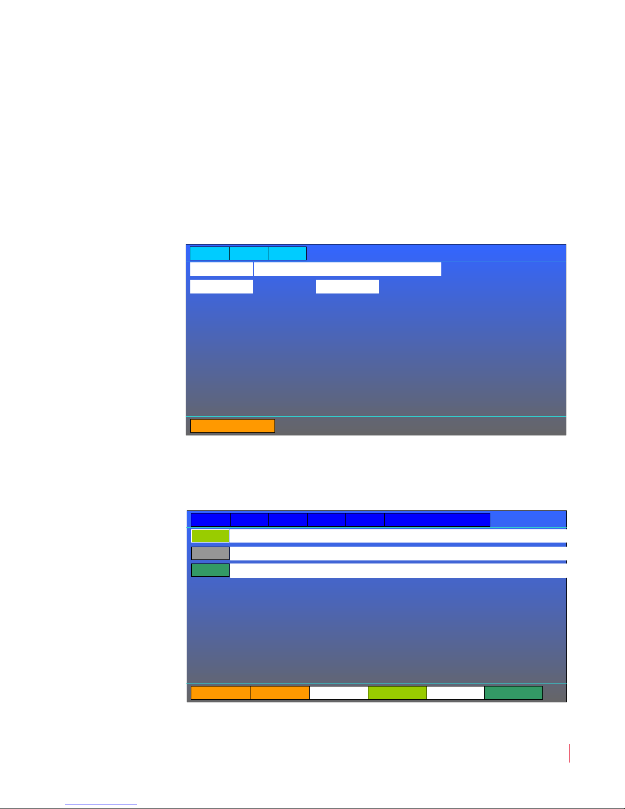
Figure 3–2 SI PID Screen
The SI PID Screen in Figure 3–2 shows the service information for
each program number. To exit the screen, press the Volume knob.
Figure 3–3 PMT PID Screen
© 2 0 1 3 W o h l e r Techn o l o g i es , I n c . A ll r i g h t s re se r v e d .
8 21 0 6 8 : M PE G - 3 2 7 0 & 42 9 0 U se r Gu i d e
25
Page 32

Ch ap t er 3 Op e r a ti on
F1 - F6 B u tt o n s
The PMT PID Screen in Figure 3–3 on page 25 shows detailed
information for the selected audio and video program map table PID.
Rotate the Volume knob to highlight the PMT PID of interest and press
it. The rotate the Volume knob and then press to select either SEL and
Exit to select that PMT PID and exit this screen and return to the MPEG
Screen, or select EXIT Only to exit this screen with no changes.
IMPORTANT:
If a PMT PID row is highlighted in bright pink, this lets you know that
the stream is encripted (scrambled). This product by design is not
intended to monitor these streams, so do not attempt to select one.
F1 - F6 Buttons
Your choice of options can be accessed directly using the function
buttons. The option or options that each button controls is set in the
Functions Menu on page 37. By default from the factory, the Function
buttons are set up as follows:
F1: By default, the F1 button will control three options: Whether
the Center marker appears, whether the Area marker appears,
and whether the Safety marker appears.
F2: By default, the F2 button will control whether the audio Level
Meters appear on the screen.
F3 - F6: By default, the F3 - F6 buttons are undefined.
Pressing the F1 through F6 buttons will light its green indicator,
showing that the option or options are in effect. Pressing the button
again removes the option or options, extinguishing the indicator.
Adjust Settings
Certain commonly accessed adjustments are accessed fairly directly by
pressing the Adjust button, lighting the green indicator in the button.
When this indicator is lit, the Volume knob is re-purposed to adjusting
the settings that follow. Pressing the Adjust button a second time exits
the menu, extinguishing the button’s indicator, as does the expiring of
the OSD Time-out set in the OSD Menu on page 41. After pressing the
8 21 0 6 8 : MPE G - 3 2 70 & 4 2 9 0 U ser G u i de
26
© 2 0 1 3 W o h l e r Te ch n o l o gie s, I n c . All r i g ht s res e r v e d .
Page 33

Ch ap t er 3 Operation
Sc r e e n Sa v e r
Adjust button, the first item in the following list appears on the screen
for adjustment. Pressing the Volume knob switches to each successive
item:
1. Backlight: Rotate the Volume knob to adjust the screen
brightness on a scale of 15% to 100%.
2. Video Blend: Rotate the Volume knob to adjust the transparency
of the on-screen displays and menus on a 30% to 100% scale.
3. Contrast: Rotate the Volume knob to adjust the video contrast on
a 40% to 100% scale.
4. Red: Rotate the Volume knob to adjust the red level on a -128 to
127 scale.
5. Blue: Rotate the Volume knob to adjust the blue level on a -128 to
126 scale.
6. Saturation: Rotate the Volume knob to adjust the video
saturation on a 0% to 100% scale.
7. Gamma: Rotate the Volume knob to adjust the video gamma on a
0 to 10 scale. On this scale, 1 implies a 10% application of the
gamma set in the Video Menu, while 9 implies a 90% application.
8. Black Level: Rotate the Volume knob to adjust the black level on
a 0 to 16 scale.
9. Panel LEDs: Rotate the Volume knob to adjust the brightness of
the panel LEDs on a 0 to 15 scale. This function on each of the
screens works in common on all four of the screens.
Screen Saver
In order to prolong the life of the displays, a Backlight Timeout Interval
is provided. Refer to the Backlight Interval item in the System Menu
on page 42. The default setting is 8 hours. After 8 hours passes with no
button presses or knob turns, the MPEG-3270 or MPEG-4290 will dim
its screens. Pressing any button or turning any knob will bring the
MPEG-3270 or MPEG-4290 back to normal operation.
© 2 0 1 3 W o h l e r Techn o l o g i es , I n c . A ll r i g h t s re se r v e d .
8 21 0 6 8 : M PE G - 3 2 7 0 & 42 9 0 U se r Gu i d e
27
Page 34

Ch ap t er 3 Op e r a ti on
Sa v i n g Yo u r O p t i o ns
Saving Your Options
When power is switched off or otherwise lost, the current option
settings in the MPEG-3270 or MPEG-4290 are preserved and are still in
effect when power is restored. In addition, 6 option memories or
Presets for each screen are provided for you to save various
configurations to be later recalled. Refer to the Preset Menu on page 43.
You may also copy these Presets from screen to screen.
Sometimes you may want to erase the option settings you have made in
any Preset and restore it to the default options that the MPEG-3270 or
MPEG-4290 was originally provided with. To do this, go to the Preset
Menu in the screen you want to restore and use the following steps:
1. Within the Preset Menu, turn the Volume knob to the Recall
Preset item. If the Preset you want to restore is already
highlighted, skip to Step 3.
2. Press the Volume knob, then turn it to the number of the Preset
you want to restore and press it again. The Preset will recall and
highlight.
3. Press the Volume knob, then turn it to the Factory selection and
press it again. The current settings as well as those in the selected
Preset will instantly return to their original default settings.
8 21 0 6 8 : MPE G - 3 2 70 & 4 2 9 0 U ser G u i de
28
© 2 0 1 3 W o h l e r Te ch n o l o gie s, I n c . All r i g ht s res e r v e d .
Page 35

Introduction
Overview
This chapter describes how to use the menu system to configure your
MPEG-3270 or MPEG-4290.
Topics
CHAPTER 4
Configuration
Topics Page
Introduction 29
Using the Menu System 30
Video Menu 32
Audio Menu 33
Marker Menu 35
UMD Options Menu 36
Functions Menu 37
GPI-In Menu 39
OSD Menu 41
System Menu 42
Preset Menu 43
Network Menu 45
Status Menu 47
MPEG Menu 47
© 2 0 1 3 Wo h l er Te c h n o l o gi e s , I n c. All r i g h t s re se r v e d .
821 0 6 8 : M PEG - 3 2 7 0 & 42 9 0 U se r Gu i d e
29
Page 36
Ch ap t er 4 Co nf i gu ra tio n
System Status
OSD Menu
Source ID
Source Position
Adjust Position
OSD Timeout
Preset Menu
Save Preset to
Load Preset from
Display Preset ID
Preset ID Position
Copy All Presets to
Preset ID
Functions Menu
Gamma Set
Blue Screen
Mono Mode
Video Scale
Level Meters
Center
Area
Safety
Audio Menu
Level Meter Display
Audio Scale
Mode Display
Meter Size
Meters
SDI-A Left Audio
SDI-A Right Audio
SDI-B Left Audio
SDI-B Right Audio
GPI-In Menu
Gamma Set
Blue Screen
Mono Mode
Video Scale
Level Meters
Center
Area
Safety
Main Menu
Video Menu
Audio Menu
Marker Menu
Functions Menu
OSD Menu
System Menu
Network Menu
Preset Menu
System Status
GPI-In Menu
UMD Options Menu
MPEG Menu
Video Menu
Gamma Select
Film Gamma
Color Temperature
Blue Screen
Mono Mode
Scale Type
Video Scale
Marker Menu
Marker Enable (All)
Marker Background
Marker Color
Center Marker
Area Marker
Safety Marker
Safety Marker Size
Area Ratio
UMD Options Menu
UMD Tally Src
UMD Enable
UMD Position
UMD Color
UMD Address
UMD ID
MPEG Menu
TS Ports
SDI-A
ASI-B
Eth UC/MC
Sync
ASI
TS
PID Type
SI PIDs
Network Menu
IP Address
IP Mask
Gateway Address
Port Number
System Menu
BNC Port A
BNC Port B
Backlight Interval
Panel LEDs
Calibration
Upgrade
Streamcast
Us in g t he Me nu S y st e m
Using the Menu System
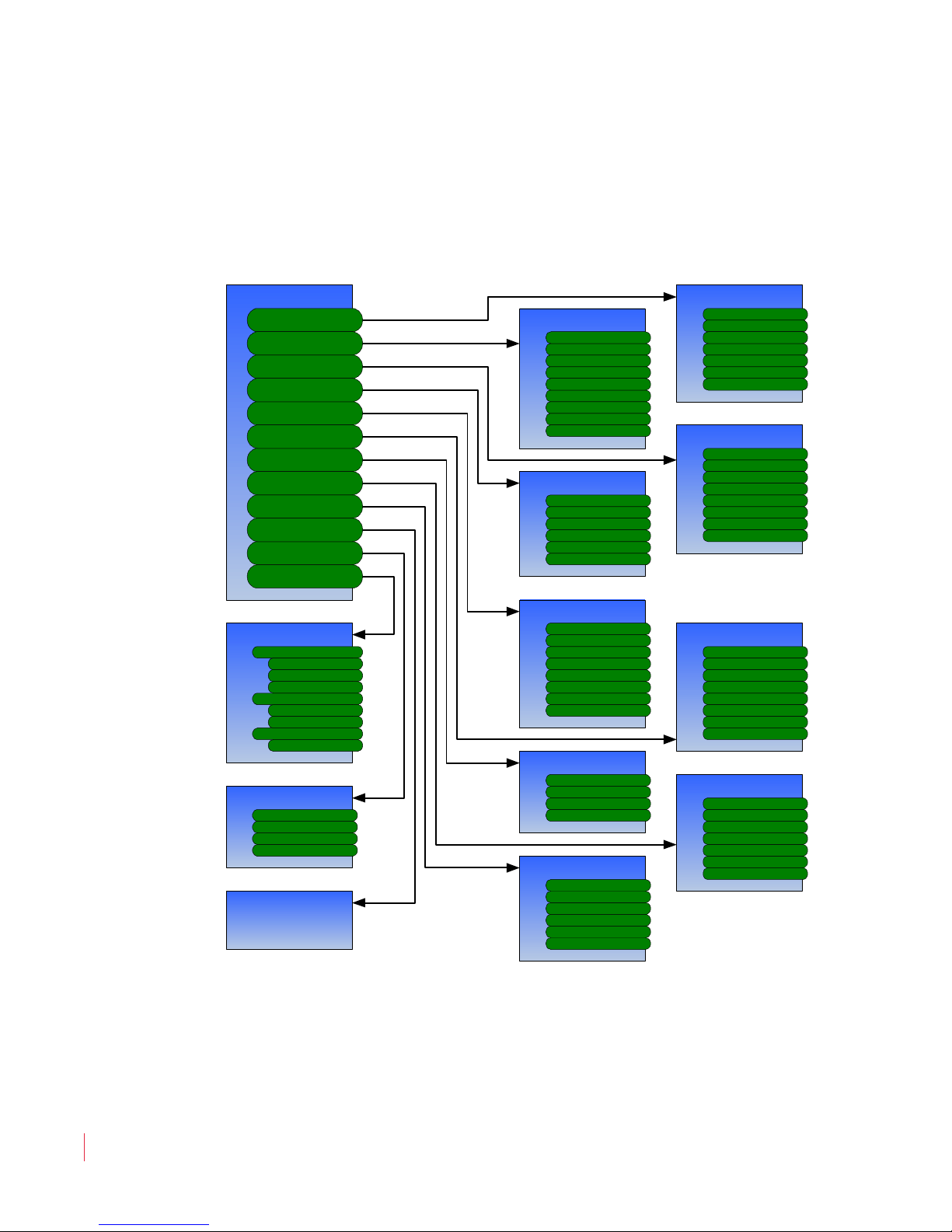
The Menu System consists of a tree of menus which list the various
options and setting that can be customized for your use. The Menu Tree
is shown in Figure 4–1.
Figure 4–1 MPEG-3270 & MPEG 4290 Menu Tree
Pressing the Menu button enters the Menu System. The first menu
that you see is the Main Menu. Most of the other menus can be
accessed from the Main Menu, which appears as shown in Figure 4–2
8 21 0 6 8 : MPE G - 3 2 70 & 4 2 9 0 U ser G u i de
30
© 2 0 1 3 W o h l e r Te ch n o l o gie s, I n c . All r i g ht s res e r v e d .
on page 31.
Page 37
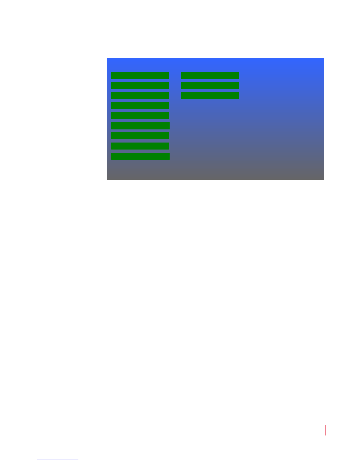
Figure 4–2 Main Menu
Video Menu
Main Menu
Audio Menu
Marker Menu
Functions Menu
OSD Menu
System Menu
Preset Menu
System Status
GPI-In Menu
Network Menu
MPEG Status
UMD Options Menu
Ch ap t er 4 Configuration
Us in g t he M e n u S ys t em
Rotate the Volume knob to highlight the menu you want and then
press to enter it. In this or any menu, press the Menu/Back button to
back out of the menu or the particular selection within that menu. The
menus are described on the following pages.
© 2 0 1 3 W o h l e r Techn o l o g i es , I n c . A ll r i g h t s re se r v e d .
8 21 0 6 8 : M PE G - 3 2 7 0 & 42 9 0 U se r Gu i d e
31
Page 38
Ch ap t er 4 Co nf i gu ra tio n
Gamma Select
Video Menu
Film Gamma
Color Temperature
Blue Screen
Video Scale
FilmUncorrected GPI
1.0 1.2 1.4 1.6 1.8 2.0 2.2 2.4 2.6 2.8
D50 D55 D65 D75
Off On GPI
GPIOff On
D93
Scale Type Zoom Stretch
Mono Mode GPIOff On
Vi d eo M en u
Video Menu
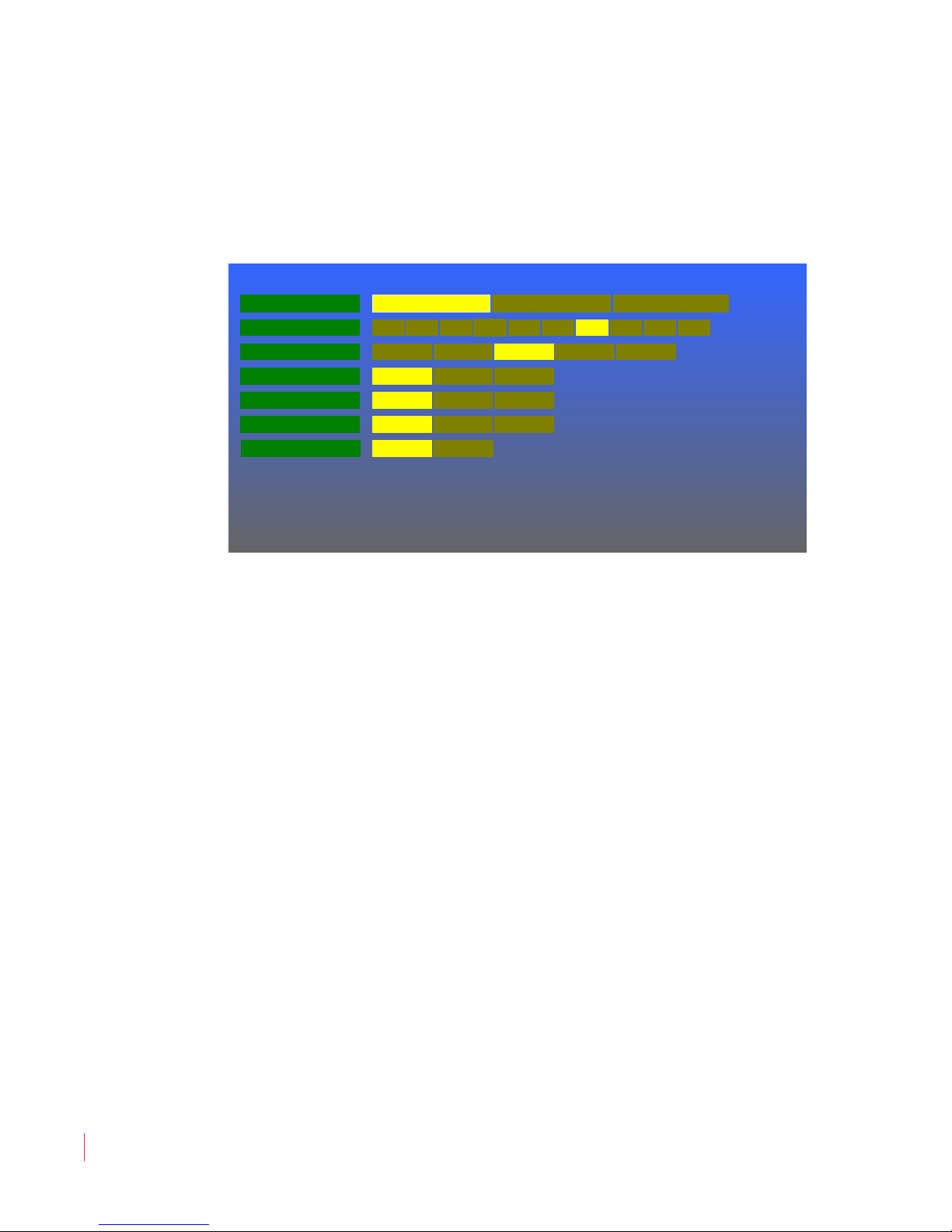
This menu customizes the video display. The Video Menu is shown in
Figure 4–3.
Figure 4–3 Video Menu
32
8 21 0 6 8 : MPE G - 3 2 70 & 4 2 9 0 U ser G u i de
© 2 0 1 3 W o h l e r Te ch n o l o gie s, I n c . All r i g ht s res e r v e d .
Rotate the Volume knob to highlight the item to be adjusted, and then
press to enter it. Again rotate the Volume knob to the option selection
and press to choose it:
1. Gamma Select: Selecting Uncorrected effectively sets a gamma
of 1.0. Selecting Film sets gamma to the value chosen in the Film
Gamma selection of this menu. Selecting GPI will allow a GPI
input, as set in the GPI-In Menu on page 39, to select whether
Uncorrected or Film is in effect.
2. Film Gamma: A selection of values is presented. The chosen
value will be used when Gamma Select is set to Film. 2.2 is the
default.
3. Color Temperature: Selections from warm to cool are provided.
D65 is the default.
4. Blue Screen: Off is the default selection. Selecting On disables
the red and green colors for alignment purposes. Selecting GPI
will allow a GPI input, as set in the GPI-In Menu on page 39, to
select whether Off or On is in effect.
5. Mono Mode: Off is the default selection and enables the color
video display. Selecting On will display only monochrome video.
Page 39
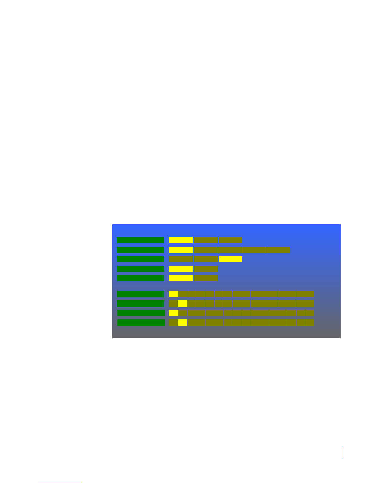
Selecting GPI will allow a GPI input, as set in the GPI-In Menu on
Level Meter Display
Audio Menu
Audio Scale
Mode Display
SDI-A Left Audio
VU Nordic BBC
VU PPM VU/PPM
DIN
1 2 3 4 5 6 7 8
SDI-A Right Audio
Meter Size Large Small
Meters All 16 Active 2
9 10 11 12 13 14 15 16
1 2 3 4 5 6 7 8 9 10 11 12 13 14 15 16
SDI-B Left Audio 1 2 3 4 5 6 7 8
SDI-B Right Audio
9 10 11 12 13 14 15 16
1 2 3 4 5 6 7 8 9 10 11 12 13 14 15 16
Ext. VU
Off On GPI
page 39, to select whether Off or On is in effect.
6. Scale Type: Zoom is the default selection. It will enlarge the
image, keeping its aspect ratio, until both the vertical and
horizontal edges reach or surpass the edges of the screen. Selecting
Stretch will enlarge both the vertical and horizontal dimensions
to reach the edge of the screen, without preserving the aspect ratio.
Audio Menu
This menu sets up the audio level meters that can appear on the display
and also defines which audio channels you will hear. The Audio Menu
is shown in Figure 4–4
Ch ap t er 4 Configuration
Au d i o M e n u
Figure 4–4 Audio Menu
Rotate the Volume knob to highlight the item to be adjusted, and then
press to enter it. Again rotate the Volume knob to the option selection
and press to choose it:
1. Level Meter Display: Selecting On causes audio level meters to
appear on the screen. Selecting Off causes them to disappear.
Either 2 or 16 meters will appear, as defined by the Meters option
in this menu. Selecting GPI Control will allow an external GPI
input, as set in the GPI-In Menu on page 39, to select whether the
audio meters appear or not. The default is On.
© 2 0 1 3 W o h l e r Techn o l o g i es , I n c . A ll r i g h t s re se r v e d .
8 21 0 6 8 : M PE G - 3 2 7 0 & 42 9 0 U se r Gu i d e
33
Page 40

Ch ap t er 4 Co nf i gu ra tio n
Au d i o M en u
2. Audio Scale: One of five audio scales for the level meters may be
selected.
• Extended VU
• VU
• Nordic
• BBC
• DIN
The default is Extended VU.
3. Mode Display: The type of level metering can be chosen. VU/
PPM is the default, causing both the average and peak levels to be
displayed simultaneously. Optionally, PPM (peak) and VU
(average) can be selected to display individually.
4. Meter Size: Larger meters are easier to see, but cover up more of
the video display. The default selection is Large. A Small
(narrower, but same height) selection is available.
5. Meters: By default, the All 16 selection will allow all 16 channels
within an SDI signal to display, with channels 1 – 8 on the left of
the screen and channels 9-16 on the right of the screen. Optionally,
Active 2 can be selected to allow only the two channels that are
selected for listening to display. The two channels will appear in
the same position that they would have been in if 16 channels were
displayed.
6. SDI-A Left Audio: This option allows you to choose the channel
to be heard in the left speaker or headphone when the SDI-A input
is picked. By default, channel 1 is selected.
7. SDI-A Right Audio: This option allows you to choose the
channel to be heard in the right speaker or headphone when the
SDI-A input is picked. By default, channel 2 is selected.
8. SDI-B Left Audio: This option allows you to choose the channel
to be heard in the left speaker or headphone when the SDI-B input
is picked. By default, channel 1 is selected.
9. SDI-B Right Audio: This option allows you to choose the
channel to be heard in the right speaker or headphone when the
SDI-B input is picked. By default, channel 2 is selected.
8 21 0 6 8 : MPE G - 3 2 70 & 4 2 9 0 U ser G u i de
34
© 2 0 1 3 W o h l e r Te ch n o l o gie s, I n c . All r i g ht s res e r v e d .
Page 41
Marker Menu
Marker Enable (All)
Marker Menu
Marker Background
Marker Color
Center Marker
Area Ratio
Normal Matte
White Green Blue Yellow Gray
Off
4:3 13:9 14:9 16:9 1.85:1 2.35:1 32:9
Red
On
Safety Marker Size 80% 85% 90% 95%
Area Marker Off On
GPI
GPI
Safety Marker Off On GPI
Off On
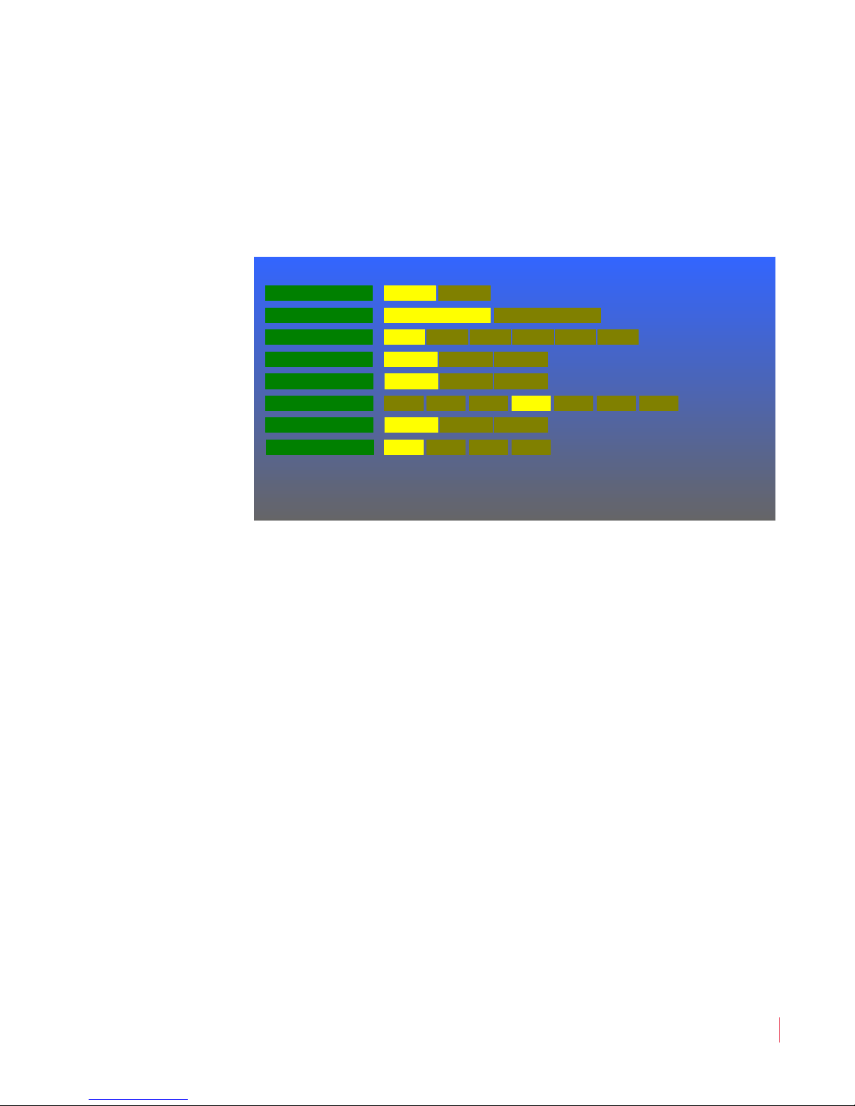
This menu defines if and how markers will appear on the screen. The
Marker Menu is shown in Figure 4–5.
Figure 4–5 Marker Menu
Ch ap t er 4 Configuration
M a rk er Me n u
Rotate the Volume knob to highlight the item to be adjusted, and then
press to enter it. Again rotate the Volume knob to the option selection
and press to choose it:
1. Marker Enable (All): Selecting On causes any markers set up in
2. Marker Background: By default the Normal choice is selected,
3. Marker Color: The color of the markers can be one of six choices.
4. Center Marker: The center marker may be turned On or Off.
5. Area Marker: The area marker may be turned On or Off. The
this menu to appear on the screen. Selecting Off will not allow any
markers to display. The default is Off.
which means that the background is transparent, allowing the
video to display normally. Matte represents a future feature.
By default the White choice is selected.
Selecting GPI control will allow an external GPI input, as set in the
GPI-In Menu on page 39, to select whether the Center Marker
appears or not. The default is Off.
aspect ratio of the Area Marker is as selected in the Area Ratio
option in this menu. Selecting GPI control will allow an external
© 2 0 1 3 W o h l e r Techn o l o g i es , I n c . A ll r i g h t s re se r v e d .
8 21 0 6 8 : M PE G - 3 2 7 0 & 42 9 0 U se r Gu i d e
35
Page 42
Ch ap t er 4 Co nf i gu ra tio n
UMD Enable
UMD Options M enu
Off On
UMD Position T Left T RightTop BottomB Left B Right
UMD ID Engineering Lab Save UMD Text
UMD Color White Green Blue Yellow GrayRed
UMD Tally Src Local RS485
A B C D E F G H I J K L M
N O P Q R S T U V W X Y Z
# + -
!
@0 1 2 3 4 5 6 7 8 9 % =
? :
[ ]
/
.
( )
Shift Space BkSp DoneClear Restore
UMD Address 0 <Save>
UM D Opt io ns Me n u
GPI input, as set in the GPI-In Menu on page 39, to select whether
the Area Marker appears or not. The default is Off.
6. Area Ratio: Seven choices of Area Marker aspect ratio are
offered. By default the 16:9 ratio is chosen.
7. Safety Marker: The area marker may be turned On or Off. The
size of the Safety Marker is as selected in the Safety Marker
Size option in this menu. Selecting GPI control will allow an
external GPI input, as set in the GPI-In Menu on page 39, to select
whether the Safety Marker appears or not. The default is Off.
8. Safety Marker Size: Seven choices of Safety Marker Size are
offered. By default the 80% size is chosen.
UMD Options Menu
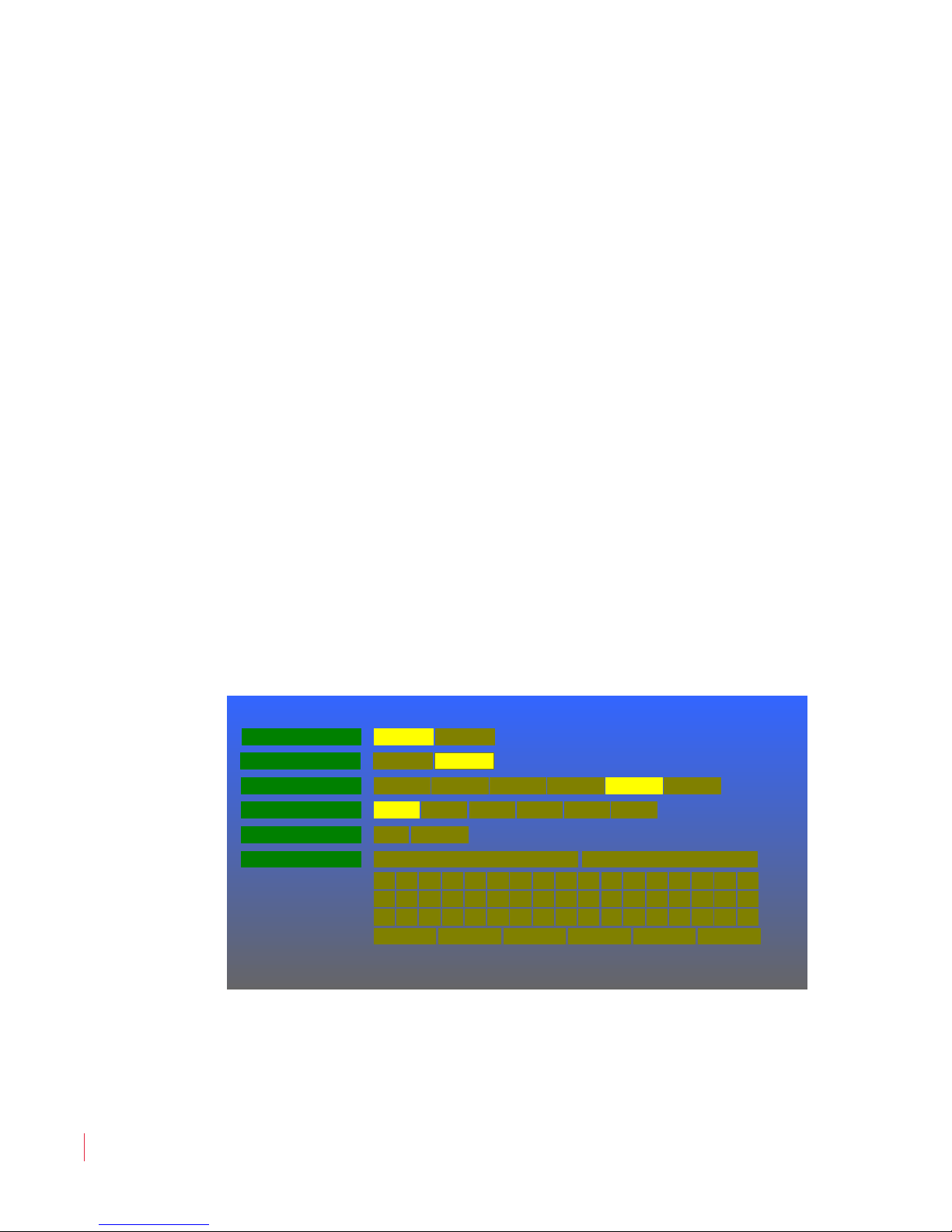
This menu lets you set how the UMD (Under Monitor Display) is
sourced and how it appears. The UMD Options Menu is shown in
Figure 4–6.
Figure 4–6 UMD Options Menu
8 21 0 6 8 : MPE G - 3 2 70 & 4 2 9 0 U ser G u i de
36
© 2 0 1 3 W o h l e r Te ch n o l o gie s, I n c . All r i g ht s res e r v e d .
Rotate the Volume knob to highlight the item to be adjusted, and then
press to enter it. Again rotate the Volume knob to the option selection
and press to choose it:
Page 43

Ch ap t er 4 Configuration
Fu nct io ns Me nu
1. UMD Tally Src: The text of the UMD Tally may be set to Local to
display the text set in the UMD ID section of this menu or it may
be set to RS485 so that it may be received from the RS485
interface on the back panel. The tally protocols supported are TSL
3.1 and 4.0. Selection between them is automatic. The default
setting is Local.
2. UMD Enable: By default, this option is set to On, allowing the
UMD set up by this menu to appear on the screen. Selecting Off
will prevent the UMD from appearing.
3. UMD Position: The UMD may be displayed at one of six locations
on the screen. By default, the Bottom location is selected.
4. UMD Color: The color of the of the UMD can be one of six choices.
By default, the White choice is selected.
5. UMD Address: The numeric keys of the on-screen keypad can be
used to set the UMD address 0 - 127. To enter the address, first
press the Volume knob one more time and then rotate it to
highlight each number and the press it to add that number to the
address. Clear, Restore, Shift, Space, Backspace, and Done
controls are also provided. Up to 3 digits may be entered. When
you are finished, select Done. <Save> will then be highlighted.
To save, press the Volume knob one more time. To abandon the
text you entered, press the Menu button.
6. UMD ID: An on-screen keypad is provided to use to enter the local
UMD text. To enter text, rotate the Volume knob to highlight each
character and the press it to add that character to the text. Clear,
Restore, Shift, Space, Backspace, and Done controls are also
provided. Up to 16 characters may be entered. When you are
finished, select Done. Save UMD Text will then be highlighted.
To save the text, press the Volume knob one more time. To
abandon the text you entered, press the Menu button.
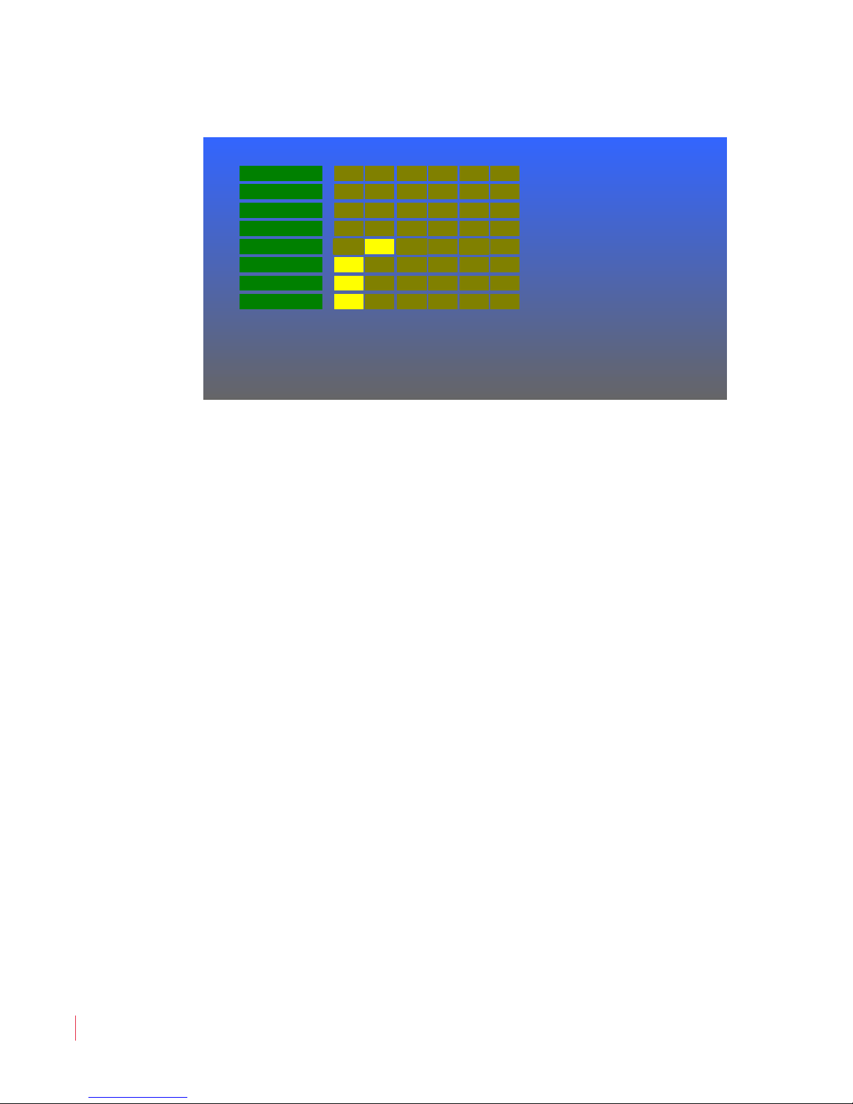
Functions Menu
This menu programs the action of the F1 through F6 function buttons
on the front panel. Each function button serves as a hot key to control
one or more functions, as desired. The Functions Menu is shown in
Figure 4–7.
© 2 0 1 3 W o h l e r Techn o l o g i es , I n c . A ll r i g h t s re se r v e d .
8 21 0 6 8 : M PE G - 3 2 7 0 & 42 9 0 U se r Gu i d e
37
Page 44
Ch ap t er 4 Co nf i gu ra tio n
Functions Menu
Blue Screen
Mono Mode
Video Scale
Level Meters
Center
Gamma Set
Area
Safety
F2F1
F2F1
F2F1
F2F1
F2F1
F2F1
F2F1
F2F1
F4F3
F4F3
F4F3
F4F3
F4F3
F4F3
F4F3
F4F3
F6F5
F6F5
F6F5
F6F5
F6F5
F6F5
F6F5
F6F5
Fu nct io ns Me nu
Figure 4–7 Functions Menu
Rotate the Volume knob to highlight the item to be adjusted, and then
press to enter it. Again rotate the Volume knob to the option selection
and press to choose it:
38
1. Gamma Set: The gamma parameters are described in the Video
Menu on page 32. The F1 through F6 buttons may control
whether gamma is set to Uncorrected or Film. By default,
neither function button controls this.
2. Blue Screen: Blue Screen is described in the Video Menu on
page 32. The F1 through F6 buttons may control whether the blue
screen is set to On or Off. By default, neither function button
controls this.
3. Mono Mode: Monochrome mode is described in the Video Menu
on page 32. The F1 through F6 buttons may control whether
monochrome mode is set to On or Off. By default, neither function
button controls this.
4. Video Scale: Video scaling is described in the Scale Type option
on the Video Menu on page 32. The F1 through F6 buttons may
control whether the scale type is set to Zoom or Stretch. By
default, neither function button controls this.
8 21 0 6 8 : MPE G - 3 2 70 & 4 2 9 0 U ser G u i de
© 2 0 1 3 W o h l e r Te ch n o l o gie s, I n c . All r i g ht s res e r v e d .
5. Level Meters: The audio level meter parameters are described in
the Audio Menu on page 33. The F1 through F6 buttons may
control whether the level meters show on the screen or not. By
default, function button F2 controls this.
Page 45
Ch ap t er 4 Configuration
GPI-In Menu
Blue Screen
Mono Mode
Video Scale
Level Meters
Center Marker
Gamma Set
Area Marker
Safety Marker
43 5
43 5
43 5
43 5
43 5
43 5
43 5
43 5
GP I- I n Me n u
6. Center: The Center Marker enable is described in the Marker
Menu on page 35. The F1 through F6 buttons may control
whether the center marker shows on the screen or not. By default,
function button F1 controls this.
7. Area: The Area Marker enable is described in the Marker Menu
on page 35. The F1 through F6 buttons may control whether the
area marker shows on the screen or not. By default, function
button F1 controls this.
8. Safety: The Safety Marker enable is described in the Marker
Menu on page 35. The F1 through F6 buttons may control
whether the safety marker shows on the screen or not. By default,
function button F1 controls this.
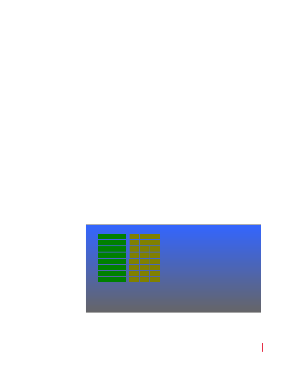
GPI-In Menu
This menu programs the action of the GPI (General Purpose Interface)
inputs. The pin numbers of each input (as well as the other pins on the
GPI connector) are shown on this menu. Each input can control
multiple functions, if desired. By default, the GPI inputs are not set to
control any function. The GPI-In Menu is shown in Figure 4–8.
Figure 4–8 GPI-In Menu
© 2 0 1 3 W o h l e r Techn o l o g i es , I n c . A ll r i g h t s re se r v e d .
8 21 0 6 8 : M PE G - 3 2 7 0 & 42 9 0 U se r Gu i d e
39
Page 46

Ch ap t er 4 Co nf i gu ra tio n
GP I -I n Me n u
Rotate the Volume knob to highlight the item to be adjusted, and then
press to enter it. Again rotate the Volume knob to the option selection
and press to choose it:
1. Gamma Set: The gamma parameters are described in the Video
Menu on page 32. The Gamma Select option in the Video Menu
must be set to GPI for a GPI input to take effect.
2. Blue Screen: Blue screen is described in the Video Menu on page
32. The Blue Screen option in the Video Menu must be set to
GPI for a GPI input to take effect.
3. Mono Mode: Monochrome mode is described in the Video Menu
on page 32. The Mono Mode option in the Video Menu must be
set to GPI for a GPI input to take effect.
4. Video Scale: Video scaling is described in the Scale Type option
on the Video Menu on page 32. The Scale Type option in the
Video Menu must be set to GPI for a GPI input to take effect.
5. Level Meters: The audio level meter parameters are described in
the Audio Menu on page 33. The Level Meter Display option in
the Audio Menu must be set to GPI for a GPI input to take effect.
6. Center Marker: The Center Marker enable is described in the
Marker Menu on page 35. The Center Marker option in the
Marker Menu must be set to GPI for a GPI input to take effect.
7. Area Marker: The Area Marker enable is described in the
Marker Menu on page 35. The Area Marker option in the Marker
Menu must be set to GPI for a GPI input to take effect.
8. Safety Marker: The Safety Marker enable is described in the
Marker Menu on page 35. The Safety Marker option in the
Marker Menu must be set to GPI for a GPI input to take effect.
8 21 0 6 8 : MPE G - 3 2 70 & 4 2 9 0 U ser G u i de
40
© 2 0 1 3 W o h l e r Te ch n o l o gie s, I n c . All r i g ht s res e r v e d .
Page 47
OSD Menu
Source Position
OSD Menu
Source ID
Adjust Position
OSD Timeout
T Right B LeftT Left
Off 5 SecOn
Center BottomTop
B Right
Off 30 Sec10 Sec 1 Min
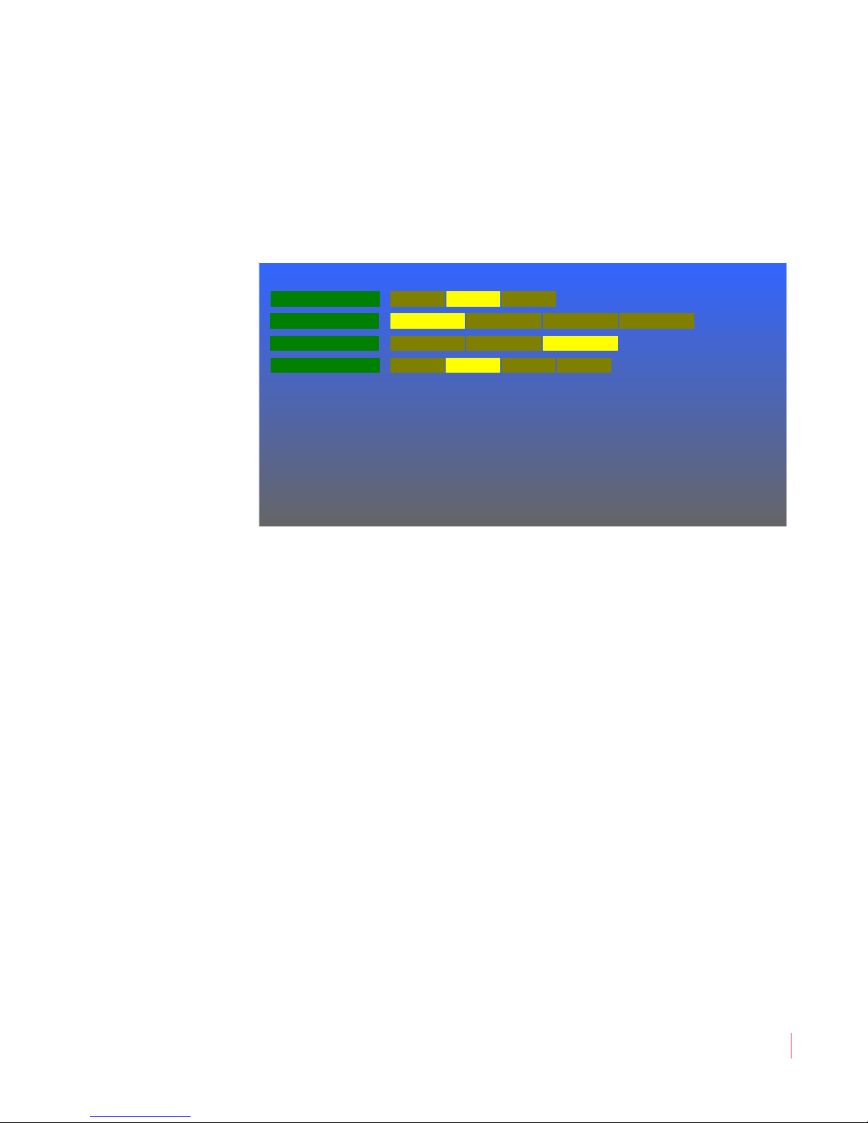
The OSD (On Screen Display) Menu sets up time-outs and positions
for various text displays. The OSD Menu is shown in Figure 4–9.
Figure 4–9 OSD Menu
Ch ap t er 4 Configuration
O S D Me n u
Rotate the Volume knob to highlight the item to be adjusted, and then
press to enter it. Again rotate the Volume knob to the option selection
and press to choose it:
1. Source ID: The Source ID display shows the type of input that
is being displayed. This display can be set to Off, On, or to only
display for 5 seconds after any source change. The default setting
is On. The position on the screen can be adjusted by the Source
Position option in this menu.
2. Source Position: The Source ID may be displayed at one of
four locations on the screen. By default, the Top Left location is
selected.
3. Adjust Position: When the Adjust button is pressed, words
appear describing what can be adjusted. The Adjust Position
option specifies one of three locations where this description will
appear on the screen. By default, the Bottom location is selected.
4. OSD Time-out: These menus may be set to either persist on the
screen indefinitely until the Menu button is pressed to exit (Off),
or they may automatically time out and disappear after one of
three time choices. By default, 10 seconds is selected.
© 2 0 1 3 W o h l e r Techn o l o g i es , I n c . A ll r i g h t s re se r v e d .
8 21 0 6 8 : M PE G - 3 2 7 0 & 42 9 0 U se r Gu i d e
41
Page 48
Ch ap t er 4 Co nf i gu ra tio n
BNC Port B
System Menu
Backlight Interval
Panel LEDs
Calibration
Upgrade
None 5m 4h 8h 24h 48h
Restore
Upgrade
SDI ASI
Off On
BNC Port A SDI ASI
Streamcast Unicast Multicast
Sy st e m Me nu
System Menu
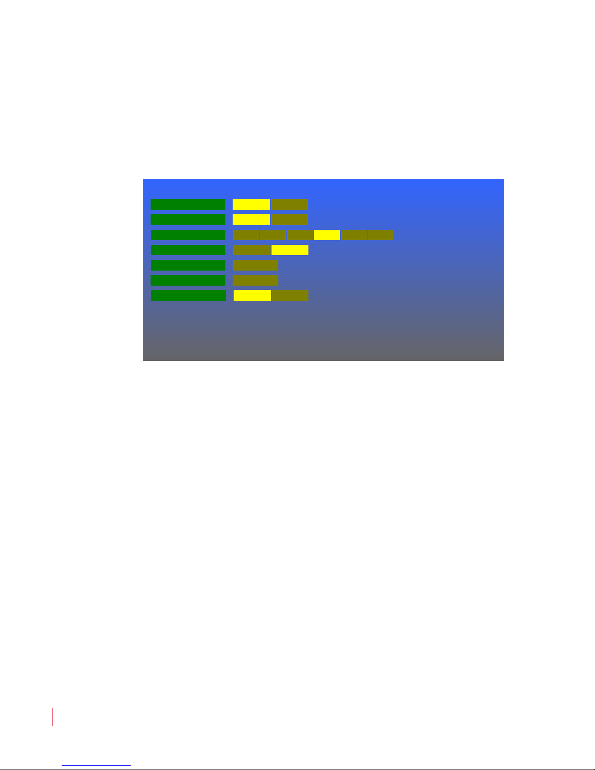
The System Menu sets up basic operational parameters for each
MPEG-3270 or MPEG-4290 screen. This menu is shown in Figure 4–10.
Figure 4–10 System Menu
42
8 21 0 6 8 : MPE G - 3 2 70 & 4 2 9 0 U ser G u i de
© 2 0 1 3 W o h l e r Te ch n o l o gie s, I n c . All r i g ht s res e r v e d .
Rotate the Volume knob to highlight the item to be adjusted, and then
press to enter it. Again rotate the Volume knob to the option selection
and press to choose it:
1. BNC Port A: Using this option, you must designate whether the
type of signaling to the Port A BNC connector on the back panel is
SDI or ASI. By default, SDI is chosen.
2. BNC Port B: Using this option, you must designate whether the
type of signaling to the Port B BNC connector on the back panel is
SDI or ASI. By default, SDI is chosen.
3. Backlight Interval: To preserve the life of the LCD backlight on
each screen, a time-out is provided. This interval can be set to
None, which leaves and backlight on all of the time, or to one of 5
time intervals. By default, 8 hours is chosen.
4. Panel LEDs: In certain environments, the Power LED and other
status LEDs can be distracting. The LEDs on the front panel can be
dimmed (Refer to Panel LEDs, Item 9 on page 27 in the Adjust
Settings section.) or they can be turned off. This option allows the
Panel LEDs to be Off while the MPEG-3270 or MPEG-4290 is in
operation. The default setting is On, which causes the Panel LEDs
Page 49

Ch ap t er 4 Configuration
Pr es e t Me n u
to indicate whenever the MPEG-3270 or MPEG-4290 is powered
and turned on.
5. Calibration: If at any time you need to set a MPEG-3270 or
MPEG-4290 screen back to its original factory calibration, this
option can be used.
6. Upgrade: If you have a software upgrade on a flash drive that you
would like to apply to the MPEG-3270 or MPEG-4290, use this
option and then following the instructions that will appear on the
screen.
7. Streamcast: Set this to Unicast or Multicast, depending upon
what will be expected in the stream.
Preset Menu
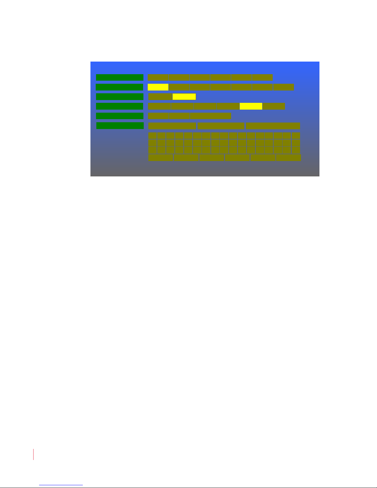
A Preset is a complete configuration. Each screen can have up to 6
Presets that can be recalled at any time to reconfigure. The Preset
Menu lets you save, recall, and name presets for each MPEG-3270 or
MPEG-4290 screen and is shown in Figure 4–11 on page 44.
To offer you maximum configuration flexibility, you can:
• Name your presets using up to 14 characters.
• Copy one preset to another.
• Copy all presets from one screen to another.
• Restore each preset to its original factory default.
© 2 0 1 3 W o h l e r Techn o l o g i es , I n c . A ll r i g h t s re se r v e d .
8 21 0 6 8 : M PE G - 3 2 7 0 & 42 9 0 U se r Gu i d e
43
Page 50
Ch ap t er 4 Co nf i gu ra tio n
Load Preset from
Preset Menu
Off OnDisplay Preset ID
Preset ID
Engineering Lab Save Preset ID
A B C D E F G H I J K L M
N O P Q R S T U V W X Y Z
# + -
!
@0 1 2 3 4 5 6 7 8 9 % =
? :
[ ]
/
.
( )
Save Preset to 1 32 4 5 6
1 32 4 5 6 Factory
Preset ID Position T Left T RightTop BottomB Left B Right
Copy All Presets to 1 32 4
1
Shift Space BkSp DoneClear Restore
Pr e s e t M e n u
Figure 4–11 Preset Menu
Rotate the Volume knob to highlight the item to be adjusted, and then
press to enter it. Again rotate the Volume knob to the option selection
and press to choose it:
1. Save Preset to: To save the current MPEG-3270 or MPEG-4290
screen configuration select one of the six preset locations and press
the Volume knob. As you rotate through each numbered preset,
its name (if any) will appear in the Preset ID option on this
menu.
2. Load Preset from: To recall a preset configuration from one of
the six preset locations to the current MPEG-3270 or MPEG-4290
screen configuration, select one of the presets and press the
Volume knob. As you rotate through each numbered preset, its
name (if any) will appear in the Preset ID option on this menu.
Alternatively, you may select Factory to recall the original factory
configuration for each screen.
3. Display Preset ID: If you have entered an Preset ID for the
currently recalled Preset, you may display this ID on the screen.
This option sets this display option On or Off. By default, it is On.
8 21 0 6 8 : MPE G - 3 2 70 & 4 2 9 0 U ser G u i de
44
© 2 0 1 3 W o h l e r Te ch n o l o gie s, I n c . All r i g ht s res e r v e d .
4. Preset ID Position: This option sets the screen location for the
Preset ID, if you have entered one and if the Display Preset ID
option in this menu is On. Six locations are offered and Bottom is
selected by default.
5. Copy All Presets to: It can be convenient to configure one of the
MPEG-3270 or MPEG-4290 screens and then simply duplicate this
Page 51

Ch ap t er 4 Configuration
IP Mask
Network Menu
1234 SavePort Number
0 1 2 3 4 5 6 7 8 9
Clear Done
IP Address 192 1168 25 Save
255 255255 0 Save
Gateway Address 192 1168 16 Save
N e tw or k M en u
configuration in each of the other screens. This option allows you
to copy all 6 presets from one screen to another.
6. Preset ID: The currently-recalled preset name and number are
shown. To name or rename a preset, recall it using the Load
Preset from function on this menu. Then click the Preset ID
function. An on-screen keypad is provided to use to enter text to
name each preset. Enter the text, by rotating the Volume knob to
highlight each character and the pressing it to add that character to
the text. Clear, Restore, Shift, Space, Backspace, and Done
controls are also provided. Up to 14 characters may be entered.
When you are finished, select Done. To save the new text, rotate
the Volume knob to highlight Save Preset ID and press it. To
quit without saving the name, press the Menu button instead.
Network Menu
Before the Ethernet port can be used, it must be configured. The
Network Menu where this is done is shown in Figure 4–12
Figure 4–12 Network Menu
Rotate the Volume knob to highlight the item to be adjusted, and then
press to enter it. Again rotate the Volume knob to the item you need to
change and press to replace it. A number in the keypad below will then
be highlighted. Rotate and press to select the new numeric entry. Use
© 2 0 1 3 W o h l e r Techn o l o g i es , I n c . A ll r i g h t s re se r v e d .
8 21 0 6 8 : M PE G - 3 2 7 0 & 42 9 0 U se r Gu i d e
45
Page 52

Ch ap t er 4 Co nf i gu ra tio n
Ne tw o r k M en u
Clear to start over and Done when finished. The changeable fields are
as follows:
1. IP Address: After each numeric field is changed, the numbers
turn from yellow to black to denote they were changed. When you
have finished, select Save. After a few seconds, the action will be
complete, the numbers will turn yellow, and IP Address will be
highlighted.
2. IP Mask: After each numeric field is changed, the numbers turn
from yellow to black to denote they were changed. When you have
finished, select Save. After a few seconds, the action will be
complete, the numbers will turn yellow, and IP Mask will be
highlighted.
3. Gateway Address: After each numeric field is changed, the
numbers turn from yellow to black to denote they were changed.
When you have finished, select Save. After a few seconds, the
action will be complete, the numbers will turn yellow, and
Gateway Address will be highlighted.
4. Port Number: When the Port Number field is changed, the
number turns from yellow to black to denote it was changed.
When you have finished, select Save. After a few seconds, the
action will be complete, the number will turn yellow, and Port
Number will be highlighted.
8 21 0 6 8 : MPE G - 3 2 70 & 4 2 9 0 U ser G u i de
46
© 2 0 1 3 W o h l e r Te ch n o l o gie s, I n c . All r i g ht s res e r v e d .
Page 53

Status Menu
System Status
Product: MPEG-3270 v1.05
S/N: xxxxxx
App Build: mpeg_26Aug2013_v1_05
LD: LD4 V1.05 CP:
CP4v105
Board Rev a1000403 FPGA Rev 20120826
IP: 192.168.153.73 MSK: 255.255.255.0 GW : 192.168.1.1
UDP Port 1024
UMD: xxx MAC: xx:xx:xx:xx:xx:xx tC: 27
The Status Menu does not provide editable options, but instead
reports on a variety of useful information, internal settings, and version
numbers.
Figure 4–13 Status Menu
Ch ap t er 4 Configuration
St at u s Me n u
MPEG Menu
The MPEG Menu is a combination status screen and menu. Its
operation is described in MPEG Screen Operation on page 23.
© 2 0 1 3 W o h l e r Techn o l o g i es , I n c . A ll r i g h t s re se r v e d .
8 21 0 6 8 : M PE G - 3 2 7 0 & 42 9 0 U se r Gu i d e
47
Page 54

Ch ap t er 4 Co nf i gu ra tio n
MP EG M e nu
8 21 0 6 8 : MPE G - 3 2 70 & 4 2 9 0 U ser G u i de
48
© 2 0 1 3 W o h l e r Te ch n o l o gie s, I n c . All r i g ht s res e r v e d .
Page 55

Introduction
Overview
Specifications, compliance information, and a block diagram of the
MPEG-3270 and MPEG-4290 are provided in this chapter.
Topics
CHAPTER 5
Specifications
Topics Page
Introduction 49
Specifications 50
Compliance 54
Technical Functional Overview 54
‘
© 2 0 1 3 Wo h l er Te c h n o l o gi e s , I n c. All r i g h t s re se r v e d .
821 0 6 8 : M PEG - 3 2 7 0 & 42 9 0 U se r Gu i d e
49
Page 56
Ch ap t er 5 Sp ec i fi ca t io ns
Sp ec i fi c at io ns
Specifications
The specifications of the audio/video monitors are listed below.
Table 5–2 MPEG-3270 Specifications
Specification
MPEG-3270
Values
Number of Screens 2
Display 7.0” diagonal
Native Aspect Ratios 16:9
Viewing Angle 80°H x 80°V
Screen Colors 16.7M
Resolution (Dots, H x V) 800 x 480
Dot Pitch (H x V, mm) 0.0635 x 0.1905
Contrast Ratio 1000:1
Pixel Response (ms) 18 typical
Luminance 400 cd/m
2
LED Backlight Life 20,000 hours
Dimensions (H x W X D) 5.5” x 19” x 2.2” (143 x 483 x 56 mm)
Shipping Weight 5.9 lbs (2.68 kg)
Net Weight 4.65 lbs (2.11 kg)
24 VDC at 3 A. CE & UL power supply.
Power Consumption
It cannot be harmed by accidental reverse
connection of power.
Operating Temperature 0°C (32°F) to 40°C (104°F)
• 2 BNC: 3G/HD-SDI or ASI (75 Ω)
50
Inputs (per screen)
• 1 HDMI
• 1 RJ-45: Tally and GPI
• 1 RS-485
Inputs (per unit)
• 1 RJ-45: Ethernet
Input and Output
(per unit)
Outputs (per screen)
• 1 USB
• 2 BNC: 3G/HD-SDI or ASI (75 Ω)
• 1 RS-485
Outputs (per unit)
• 1/8” Headphone Jack
Space Required 3 RU
Supplied Accessories DC power adapter
Note:
8 21 0 6 8 : MPE G - 3 2 70 & 4 2 9 0 U ser G u i de
© 2 0 1 3 W o h l e r Te ch n o l o gie s, I n c . All r i g ht s res e r v e d .
All specifications are subject to change without notice.
Page 57
Ch ap t er 5 Specifications
Table 5–3 MPEG-4290 Specifications
Sp ec ifi c a t io ns
Specification
MPEG-4290
Values
Number of Screens 2
Display 9.0” diagonal
Native Aspect Ratios 16:9
Viewing Angle 88°H x 88°V
Screen Colors 16.7M
Resolution (Dots, H x V) 800 x 480
Dot Pitch (H x V, mm) 0.082 x 0.246
Contrast Ratio 600:1
Pixel Response (ms) 25 typical
Luminance 400 cd/m
2
LED Backlight Life 20,000 hours
Dimensions (H x W x D) 7” x 19” x 2.2” (178 x 483 x 56 mm)
Shipping Weight 7.3 lbs (3.31 kg)
Net Weight 6.05 lbs (2.75 kg)
24 VDC at 3 A. CE & UL power supply.
Power Consumption
It cannot be harmed by accidental reverse
connection of power.
Operating Temperature 0°C (32°F) to 40°C (104°F)
• 2 BNC: 3G/HD-SDI or ASI (75 Ω)
Inputs (per screen)
• 1 HDMI
• 1 RJ-45: Tally and GPI
• 1 RS-485
Inputs (per unit)
• 1 RJ-45: Ethernet
Input and Output
(per unit)
Outputs (per screen)
• 1 USB
• 2 BNC: 3G/HD-SDI or ASI (75 Ω)
• 1 RS-485
Outputs (per unit)
• 1/8” Headphone Jack
Space Required 4 RU
Supplied Accessories DC power adapter
© 2 0 1 3 W o h l e r Techn o l o g i es , I n c . A ll r i g h t s re se r v e d .
8 21 0 6 8 : M PE G - 3 2 7 0 & 42 9 0 U se r Gu i d e
51
Page 58
Ch ap t er 5 Sp ec i fi ca t io ns
Sp ec i fi c at io ns
The acceptable signal input formats are listed below.
Table 5–4 Acceptable Signal Input Formats
Category Signal Types
3G-SDI
(SMPTE-425M, Level A)
HD-SDI
(SMPTE-292)
MPEG / ASI
SMPTE-274: 1080p (60/59.94/50)
SMPTE-296M: 720p (60/59.94/50/
30/29.97/25/24/
23.98)
SMPTE-260M: 1035i (60/59.94)
SMPTE-274: 1080i (60/59.94/50)
SMPTE-274: 1080psF (24/23.98)
SMPTE-274: 1080p (30/29.97/25/24/
23.98)
704 x 480i (60/59.94)
704 x 576i (50)
720 x 480i (60/59.94)
720 x 480p (60/59.94)
720 x 576i (50)
1280 x 720p (60/59.94/50/30/29.97/
25/24/23.98)
1440 x 1080i (60/59.94/50)
1920 x 1080i (60/59.94/50)
1920 x 1080p (60/59.94/50/30/29.97/
25/24/23.98)
1920 x 1088i (60/59.94/50)
1920 x 1088p (60/59.94/50/30/29.97/
25/24/23.98)
8 21 0 6 8 : MPE G - 3 2 70 & 4 2 9 0 U ser G u i de
52
© 2 0 1 3 W o h l e r Te ch n o l o gie s, I n c . All r i g ht s res e r v e d .
Page 59
Ch ap t er 5 Specifications
Sp ec ifi c a t io ns
Table 5–4 Acceptable Signal Input Formats
Category Signal Types
525i - NTSC
625i - PAL
525i - PAL-M
720 x 480i (59.94)
720 x 576i (50)
720 x 480p (59.94)
720 x 576p (50)
HDMI
1280 x 720p (60/59.94/50)
1920 x 1080i (60/59.94/50)
640 x 480 (60)
800 x 600 (60)
1024 x 768 (60)
1280 x 1024 (60)
1600 x 1200 (60)
1920 x 1080p (60/59.94/50/30/29.97/
25/24/23.98)
TS Protocols
SPTS/MPTS-ASI, Unicast-IP/IGMP
UDP/RTP
100 kbs - 30 Mbps CBR, MPEG-2 4:2:0
MPEG Video (ASI/IP)
MP @ML/HL/HP, MPEG-4
4:2:0 (H.264 MP/LP to L4.2)
MPEG Audio
MPEG-1/2 Layer II, AAC-LC 16-384
kbps
Compliance
This equipment has been tested and found to comply with the limits for
a Class A digital device, pursuant to part 15 of the FCC Rules. These
limits are designed to provide reasonable protection against harmful
interference when the equipment is operated in a commercial
environment. This equipment generates, uses, and can radiate radio
frequency energy and, if not installed and used in accordance with the
instruction manual, may cause harmful interference to radio
communications. Operation of this equipment in a residential area is
likely to cause harmful interference in which case the user will be
required to correct the interference at his own expense.
© 2 0 1 3 W o h l e r Techn o l o g i es , I n c . A ll r i g h t s re se r v e d .
8 21 0 6 8 : M PE G - 3 2 7 0 & 42 9 0 U se r Gu i d e
53
Page 60

Ch ap t er 5 Sp ec i fi ca t io ns
Te c h n ic al Fu n c t io na l O v e r v i ew
Technical Functional Overview
The following block diagrams (Figure 5–14 and Figure 5–15) show the
overall functionality of the MPEG-3270 and MPEG-4290 monitors.
8 21 0 6 8 : MPE G - 3 2 70 & 4 2 9 0 U ser G u i de
54
© 2 0 1 3 W o h l e r Te ch n o l o gie s, I n c . All r i g ht s res e r v e d .
Page 61
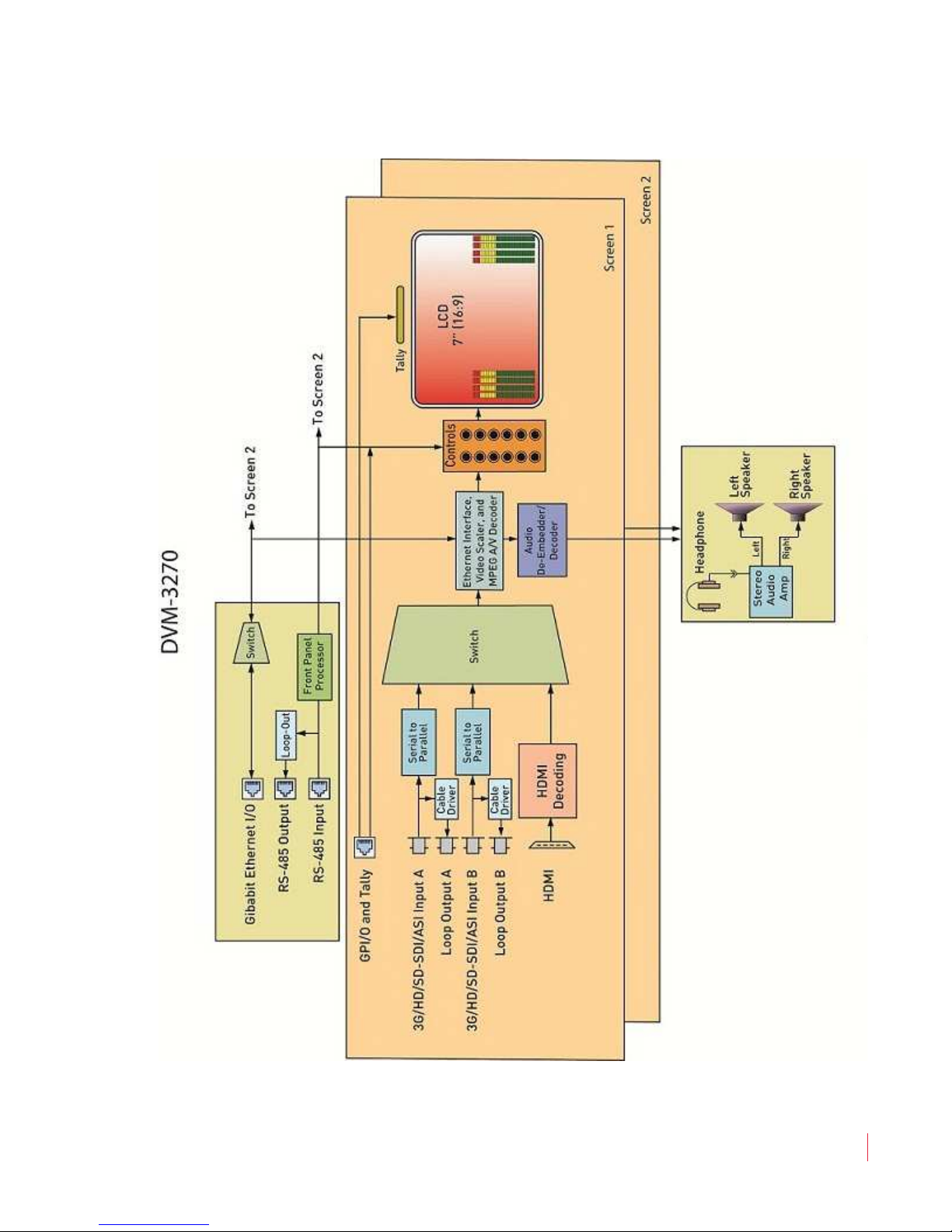
Ch ap t er 5 Specifications
Te c h n ic al Fu nc t i o na l O ve rv i ew
Figure 5–14 MPEG-3270 Block Diagram
© 2 0 1 3 W o h l e r Techn o l o g i es , I n c . A ll r i g h t s re se r v e d .
8 21 0 6 8 : M PE G - 3 2 7 0 & 42 9 0 U se r Gu i d e
55
Page 62
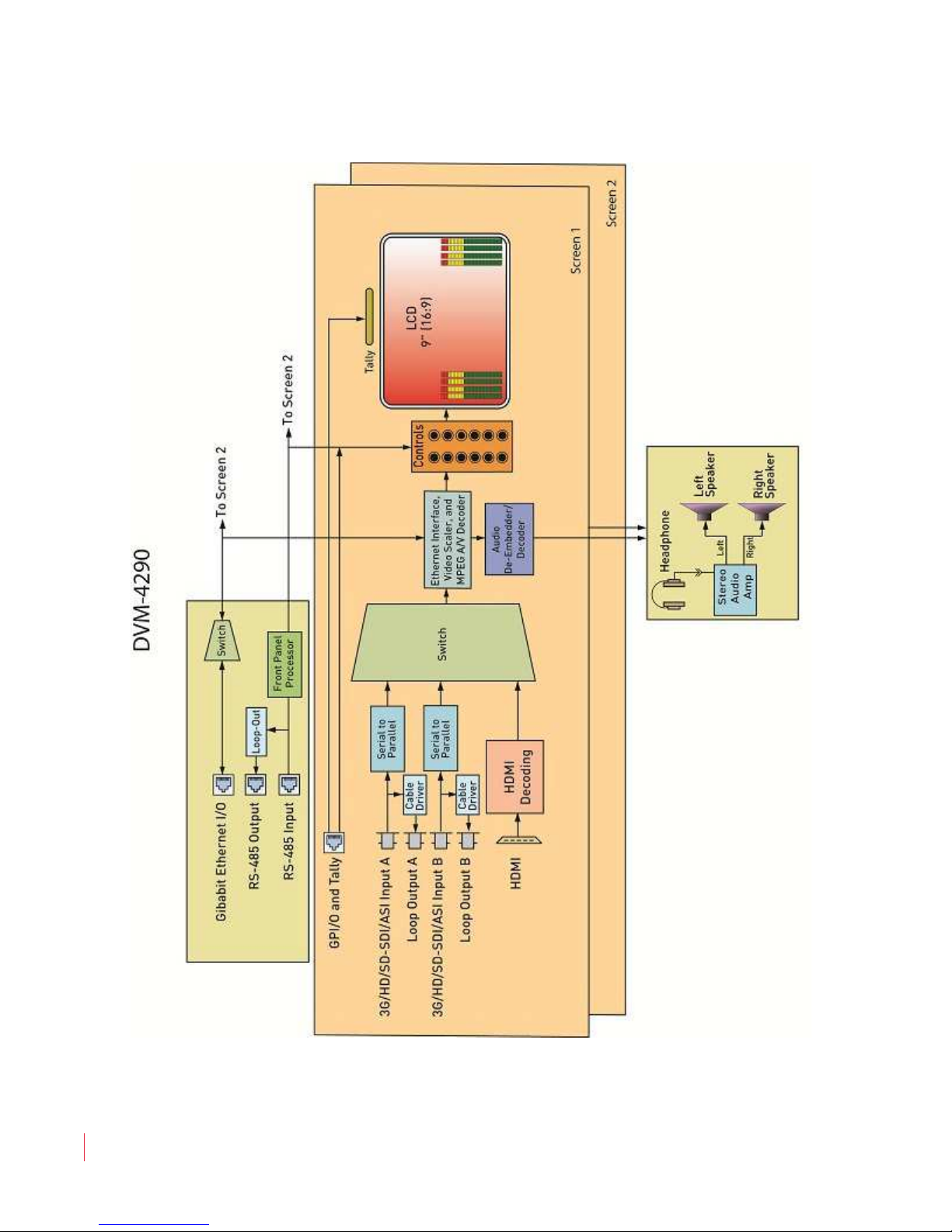
Ch ap t er 5 Sp ec i fi ca t io ns
Te c h n ic al Fu n c t io na l O v e r v i ew
Figure 5–15 MPEG-4290 Block Diagram
8 21 0 6 8 : MPE G - 3 2 70 & 4 2 9 0 U ser G u i de
56
© 2 0 1 3 W o h l e r Te ch n o l o gie s, I n c . All r i g ht s res e r v e d .
 Loading...