

Wohler iAM-MADI-8, iAM-MADI-16 User Manual

iAM-MADI
• iAM-MADI -8 • iAM-MADI -16
1RU, 8/16 of 64-Channel, MADI Audio Monitor
User Guide
(Software Release: V1.4)
Part Number 821804, Revision A

Page 2
© 2015 Wohler Technologies, Inc. All rights reserved.
This publication is protected by federal copyright law. No part of this publication may be copied or
distributed, stored in a retrieval system, or translated into any human or computer language in any
form or by any means electronic, mechanical, manual, magnetic, or otherwise, or disclosed to third
parties without the express written permission of Wohler Technologies.
Reproduction
Licensed users and authorized distributors of Wohler Technologies, Inc. products may copy this
document for use with Wohler Technologies., Inc. products provided that the copyright notice above
is included in all reproductions.
Customer Support
Wohler Technologies, Inc. 31055 Huntwood Avenue
Hayward, CA 94544 www.wohler.com
Phone: 510-870-0810
FAX: 510-870-0811
US Toll Free: 1-888-596-4537 (1-888-5-WOHLER)
Web: www.wohler.com Sales: sales@wohler.com
Support: support@wohler.com
Disclaimers
Even though Wohler Technologies, Inc. has tested its equipment and software, and reviewed the
documentation, Wohler Technologies, Inc. makes no warranty or representation, either express or
implied, with respect to software, documentation, their quality, performance, merchantability, or
fitness for a particular purpose.
In no event will Wohler Technologies, Inc. be liable for direct, indirect, special, incidental, or
consequential damages resulting from any defect in the hardware, software, or its documentation,
even if advised of the possibility of such damages.
Some states do not allow the exclusion or limitation for incidental or consequential damages, so the
above exclusion or limitation may not apply to you.
Printing
This document is intended to be printed on a duplex printer, such that the copy appears on both
sides of each page. This ensures that all new chapters start on a right-facing page.
This document looks best when printed on a color printer since some images may be indistinct when
printed on a black and white printer.
PDF
All text strings underlined in
this shade of blue
are hyperlinks within this document.
Other Technologies and Products
Google Chrome is a registered trademark of Alphabet Inc. Microsoft Windows and Internet Explorer
are registered trademarks of Microsoft Corporation. Evertz and MAGNUM are registered trademarks
of Evertz Microsystems Ltd.
Last Update
December 11, 2015

Page 3
Contents
User Guide .................................................... 1
TABLE OF CONTENTS ...................................... 3
Contents ..................................................................... 3
CHAPTER 1: Installation ................................... 5
Introduction ................................................................ 5
TABLE OF CONTENTS
Overview ............................................................. 5
Safety ........................................................................ 5
Instructions .......................................................... 5
Safety Symbols ..................................................... 6
Mounting .............................................................. 6
Heat Dissipation .................................................... 6
Sympathetic Vibration ............................................ 7
Mechanical Bracing ................................................ 7
Electrical Interference ............................................ 7
Power .................................................................. 7
Compliance ................................................................. 7
FCC ..................................................................... 7
ICES-003 ............................................................. 7
CHAPTER 2: Local Operation ............................. 8
Front Panel .................................................................. 8
Rear Panel ................................................................... 9
Channel Displays ........................................................ 10
Preset / Config Menu................................................... 11
Preset Selection ......................................................... 11
View Current Version .................................................. 11
View Current IP Address .............................................. 11
Reset IP Address ........................................................ 11
Transfer Presets via USB ............................................. 12

Page 4
CHAPTER 3:
Specifications .............................12
Figure 3–1: IAM-MADI Block Diagram ..................... 13
CHAPTER 4: Using the iAM-MADI Web GUI .........14
Web Browser / Control Device ...................................... 14
First Time- IP Assignments .......................................... 14
Dashboard ................................................................ 15
Sign In ..................................................................... 16
Channel Naming ......................................................... 17
Configuration Setup .................................................... 17
System Setup ............................................................ 19
Network Setup ........................................................... 20
Database Management ................................................ 20
Export Configuration ............................................ 20
Import Configuration ........................................... 21
Save / Restore Database (DB) ...................................... 21
APPENDIX A: .................................................23
Software Upgrades .........................................23
Introduction .............................................................. 23
Download the Software ............................................... 23
Installing the Software ................................................ 23

Page 5
By design, this monitor will only plug into a three-prong outlet for your safety. If the
plug does not fit into the outlet, contact an electrician to replace the obsolete outlet.
CHAPTER 1: Installation
Introduction
Overview
The iAM-MADI units are 1RU multichannel MADI audio monitors with BNC input and
output coax and optional optical fiber connections. Optical fiber connections require
an optional SFP hardware module and software license. Refer to Specifications
section for or contact Wohler sales for more information.
The iAM-MADI has individual channel volume controls and mute switches. Any
channel in the MADI stream may be audibly monitored and mixed with the other
selected channels. The IAM-MADI is small, low-cost, and simple to operate. Its
setup configuration can easily be copied to other IAM-MADI units.
Setups are created with a web browser over a network connection. Each iAM-MADI
can be configured with a number of presets. Nothing about the configurations of
those predefined setups can be changed from the front panel. This prevents less
experienced or hurried operators from making accidental setup changes that could
compromise their usage of the unit. It also reduces operator training to a minimum.
Safety
Instructions
1. Read, keep, and follow all of these instructions; heed all warnings.
2. Do not use this equipment near water.
3. Use only a dry cloth to clean the equipment.
4. Do not block any ventilation openings.
5. Do not install near any heat source such as a radiator, heat register, amplifier, or
stove.
6. Do not attempt to plug the unit into a two-blade outlet (with only two prongs of
equal width).
7. Protect the power cord from being walked on or pinched, particularly at plug’s
source on the equipment and at the socket.
8. Use only the attachments/accessories specified by the manufacturer.
Page 6
Clearance
Surface
24”
Front
3”
Rear
2”
Sides
1.75”
Top and Bottom (if either radiates heat)
0”
Top and Bottom (if no heat)
The symbol to the left warns of electric shock hazard inside or outside the
unit. Disconnect the power cord before removing access panels when
installing upgrades. Only qualified service personnel are to operate the
equipment with covers removed, and are to exercise caution to avoid
personal injury.
To reduce noise, the monitor does not have any fans. As a result, the heat
generated by the class D power amplifiers, power supplies, and other
components is vented by slots in the sides and back of the unit. Therefore,
as a safety precaution, you must allow proper ventilation on these surfaces.
9. Unplug the equipment during lightning storms or when unused for long periods
of time.
10. Refer all servicing to qualified service personnel. Servicing will be required
under all of the following conditions:
a. The equipment has been damaged in any way, such as when the power-
supply cord or plug is damaged.
b. Liquid had been spilled or objects have fallen onto the equipment.
c. The equipment has been exposed to rain or moisture.
d. The equipment does not operate normally.
e. The equipment has been dropped.
Safety Symbols
Mounting
The unit is designed for a standard 19" rack. Install it at ear/eye level for best high
frequency response and visual observation of the display screens. Please adhere to
the following clearances:
Heat Dissipation
The ambient temperature inside the mounting enclosure should not exceed 40°
Celsius (104° Fahrenheit). Adjacent devices can be rack mounted (or stacked) in
proximity to the unit if this temperature is not exceeded. Otherwise, allow a 1RU
(1.75”/44.45mm) space above and below the unit for air circulation.

Page 7
Sympathetic Vibration
Sympathetic vibration from other equipment (cables, etc.,) in the rack may be
serious enough to interfere with the unit’s sound quality. If you experience
sympathetic vibrations, use thin card stock, felt, foam, or weather-stripping
between the vibrating surfaces. Tie loose cables securely with cable ties.
Mechanical Bracing
The 1RU chassis is securely attached to the front panel. In addition, the chassis has
mounting tabs through which you attach it to the rack rail. This feature will reduce
or eliminate rear bracing requirements in many mobile/portable applications. The
weight of internal components is distributed fairly evenly around the unit.
Electrical Interference
Be careful to avoid mismatched cable types and other similar causes of undesired
reflections in digital signal systems. If severe enough, such reflections can result in
corruption of the digital data stream. As with any audio equipment, maximum
immunity from electrical interference requires the use of shielded cable; however,
satisfactory results can sometimes be obtained without it. The internal circuitry
ground is connected to the chassis.
Power
The unit comes with a standard internal power supply and connects an A/C mains
power source (60W, 100 to 240 VAC, ±10%, 50/60Hz) through the IEC connector
provided on the rear panel of the unit.
When the mains plug or appliance coupler is used as the disconnect device, the
disconnect device should remain operable.
Compliance
FCC
This equipment has been tested and found to comply with the limits for a Class A
digital device, pursuant to part 15 of the FCC Rules. These limits are designed to
provide reasonable protection against harmful interference when the equipment is
operated in a commercial environment. This equipment generates, uses, and can
radiate radio frequency energy and, if not installed and used in accordance with the
instruction manual, may cause harmful interference to radio communications.
Operation of this equipment in a residential area is likely to cause harmful
interference, in which case the user will be required to correct the interference at
their own expense.
ICES-003
This Class A digital apparatus complies with Canadian ICES-003.
Cet appareil numérique de la classe A est conforme à la norme NMB-003 du
Canada.
Page 8
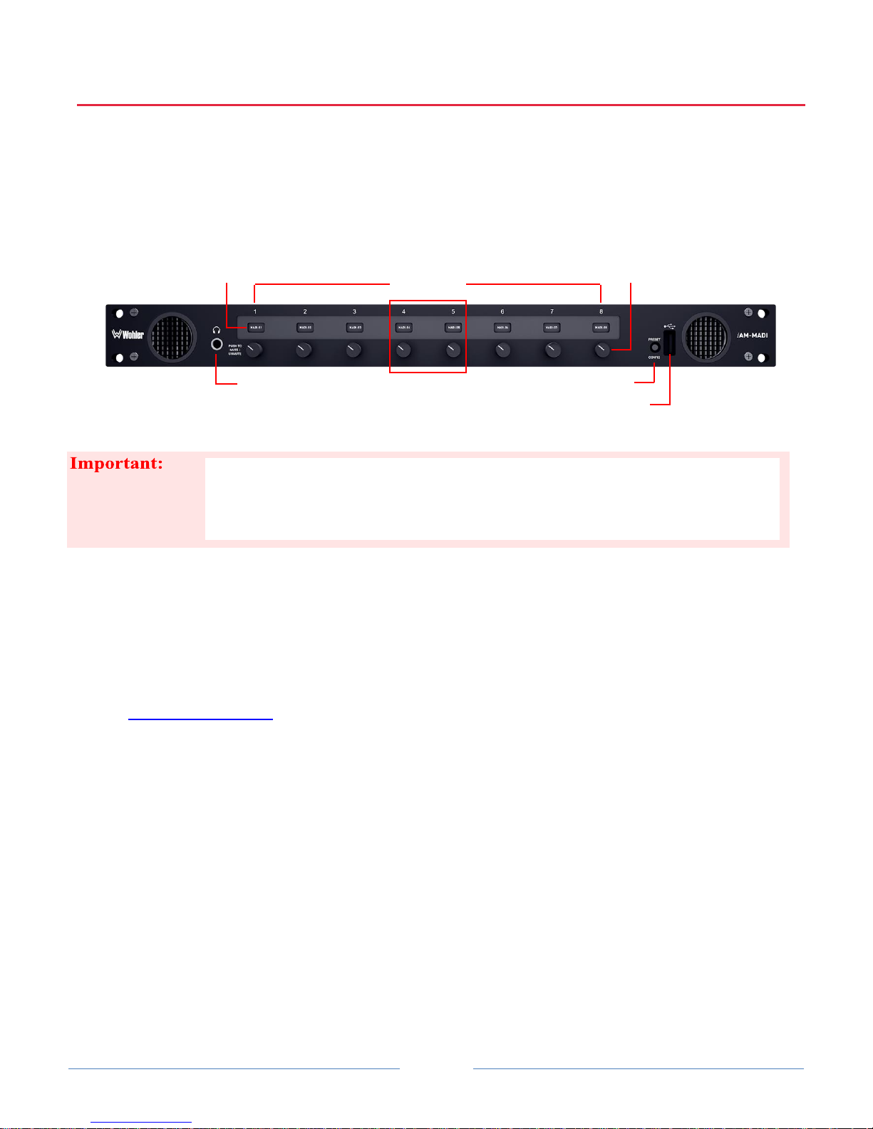
The number above the channel control strips does not indicate any particular source
channel number or arrangement. Strip numbers only serve as references for channel
configurations at the Web GUI level. Different presets typically have different
channel numbers assigned to control strips.
Right
Speaker
Strip-Channel
Displays
Left
Speaker
Control
Strips
Headphone Jack
Preset/Config Switch
USB Port
Volum
Channel
Volume/Mute
CHAPTER 2: Local Operation
Front Panel
Figure 2–1: Front Panel Layout
We use audio mixer terminology of “strips” when referring to generic control
functions or individual items within a control (strip) group. When we say “channel”
we are generally referring to a particular source channel or an individual channel
within an audio group—either here at the front panel or externally as part of the
audio system being monitored.
The control strip display label default is to display the MADI channel number, but
may be changed in the Web GUI to be any displayable text or numbers from the
Channel Naming page.
Speakers: Audio monitoring is achieved through the use of class D
amplifiers driving two (left/right) wide range speakers.
Headphone Jack: A 1/4" jack for an optional headphone is provided on the
front panel. Speaker audio mutes when headphones are plugged in.
Channel Volume/Mute: Rotating the volume knob adjusts the individual
level of each corresponding channel. Pressing the knob mutes or unmutes
channel.
Preset / Config Switch: Pressing this switch activates a menu for preset
selection and configuration status information.
USB Port: This USB 2.0 Type A connector allows you to use a flash drive
(not supplied) to perform software updates and copy system configurations
to another IAM-MADI or to a PC.
 Loading...