

Wohler iAM-AUDIO-2 User Manual

iAM-AUDIO-2
2RU Multi-Channel Touch Screen Audio Monitor
User Guide
Part Number 821808, Revision I

© 2018 Wohler Technologies, Inc. All rights reserved.
This publication is protected by federal copyright law. No part of this publication may be copied or
distributed, stored in a retrieval system, or translated into any human or computer language in any
form or by any means electronic, mechanical, manual, magnetic, or otherwise, or disclosed to third
parties without the express written permission of Wohler Technologies.
Reproduction
Licensed users and authorized distributors of Wohler Technologies, Inc. products may copy this
document for use with Wohler Technologies., Inc. products provided that the copyright notice above
is included in all reproductions.
Customer Support
Wohler Technologies, Inc.
1280 San Luis Obispo Ave
Hayward, CA, 94544
Phone: 510-870-0810
Web: www.wohler.com
Sales: sales@wohler.com
Support: support@wohler.com
Disclaimers
Even though Wohler Technologies, Inc. has tested its equipment and software, and reviewed the
documentation, Wohler Technologies, Inc. makes no warranty or representation, either express or
implied, with respect to software, documentation, their quality, performance, merchantability, or
fitness for a particular purpose.
In no event will Wohler Technologies, Inc. be liable for direct, indirect, special, incidental, or
consequential damages resulting from any defect in the hardware, software, or its documentation,
even if advised of the possibility of such damages.
Some states do not allow the exclusion or limitation for incidental or consequential damages, so the
above exclusion or limitation may not apply to you.
PDF
All text strings appearing in this shade of blue are hyperlinks.
Other Technologies and Products
Google Chrome is a registered trademark of Alphabet Inc.
Microsoft Windows and Internet Explorer are registered trademarks of Microsoft Corporation.
Embrionix is a registered trademark of Embrionix Design.
Dante and Brooklyn are registered trademarks of Audinate Pty Ltd.
Ravenna is a registered trademark of ALC NetworX GmbH.
Bach is a registered trademark of Coveloz.
All product names, logos, and brands are property of their respective owners. All company, product
and service names used in this document are for identification purposes only. Use of these names,
logos, and brands does not imply endorsement.
Last Update
August 17, 2018
Page 2

TABLE OF CONTENTS
Table of Contents
User Guide..........................................................................................1
TABLE OF CONTENTS............................................................................3
Table of Contents .............................................................................................3
CHAPTER 1: Installation ........................................................................6
Introduction ....................................................................................................6
Overview...............................................................................................6
Safety.............................................................................................................6
Instructions ...........................................................................................6
Safety Symbols......................................................................................7
Mounting...............................................................................................7
Heat Dissipation .....................................................................................7
Sympathetic Vibration.............................................................................8
Mechanical Bracing .................................................................................8
Electrical Interference .............................................................................8
Power ...................................................................................................8
Compliance .....................................................................................................8
FCC ......................................................................................................8
ICES-003 ..............................................................................................9
CHAPTER 2: Local Operation ................................................................ 10
Local vs Remote Operation ..............................................................................10
Startup .........................................................................................................10
Front Panel....................................................................................................10
Rear Panel .....................................................................................................12
SFP-2022-6 / SFP-2110 Address Setup .............................................................15
Channel Meters and Touch Operations ..............................................................16
Dolby Zoom Screen ........................................................................................17
Menu / Option Touchscreen .............................................................................19
Audio Preset ........................................................................................20
Source Select ......................................................................................21
System Information..............................................................................22
System Options ...................................................................................23
Network Settings .................................................................................23
Speaker Options ..................................................................................25
System Update ....................................................................................26
Factory Reset ......................................................................................27
System Reboot ....................................................................................28
CHAPTER 3:
Technical Info ................................................................ 29
CHAPTER 4: The iAM-AUDIO Web GUI .................................................. 34
Web Browser / Control Device .........................................................................34
Page 3

First Time IP Assignments ...............................................................................34
Peer-to-Peer Connection .......................................................................34
Network Connection .............................................................................35
Dashboard.....................................................................................................36
Remote Monitor .............................................................................................37
System Preference .........................................................................................38
Sign In .........................................................................................................39
Configure Presets ...........................................................................................40
Database Management ...................................................................................44
Export Configuration.............................................................................44
Import Configuration ............................................................................45
Database (DB) Save / Restore .........................................................................46
Scan Network - Discovery ...............................................................................47
Network Setup ...............................................................................................48
System Setup ................................................................................................49
SFP Status ..........................................................................................50
Factory Reset ................................................................................................51
Reboot System ..............................................................................................52
APPENDIX A: Software Upgrades.......................................................... 53
Introduction ..................................................................................................53
Download the Software ...................................................................................53
Update Methods .............................................................................................53
Local Update from the Front Panel....................................................................54
Updating Via the Web GUI...............................................................................57
Updating an iAM-AUDIO Remotely ....................................................................58
Updating Multiple iAM-AUDIO Units ..................................................................59
APPENDIX B: Dante Network Setup ...................................................... 62
Introduction ..................................................................................................62
What is in the iAM-AUDIO for Dante ................................................................. 63
DanteTM Device Setup .....................................................................................64
Dante Clock Selection .....................................................................................65
Channel Names..............................................................................................65
AES67 ..........................................................................................................66
Device Lock ...................................................................................................67
Dante Firmware Upgrades ...............................................................................68
DanteTM Legal Disclosures................................................................................68
APPENDIX C: Ravenna Network Setup .................................................. 69
Introduction ..................................................................................................69
What is in the iAM-AUDIO for Ravenna..............................................................69
RAVENNA-Compatible Talker/Listener .....................................................69
AVB Ethernet Features ..........................................................................69
BACH™ Controller Interface...................................................................70
Home Page....................................................................................................71
Configuration/Device Management ...................................................................71
Controller Cloud
..........................................................................................73
Page 4

Sync
............................................................................................................74
Source Streams
Stream Destinations
Patch Panel
Troubleshooting .............................................................................................79
Ravenna Firmware Upgrades ...........................................................................79
..........................................................................................75
...................................................................................76
.................................................................................................78
APPENDIX D: API Documentation ......................................................... 80
Introduction ..................................................................................................80
API: Presets ..................................................................................................80
Get available presets ............................................................................80
Get preset information ..........................................................................81
Get current active preset.......................................................................87
Preset Activation ..................................................................................87
Setting Mute/Unmute Clusters ...............................................................88
Setting Solo Cluster..............................................................................90
Setting Solo Channel ............................................................................91
Source Select ......................................................................................92
HTTP Routing Table ........................................................................................94
Status Codes .................................................................................................94
Page 5

Important:
By design, this monitor will only plug into a three
-
prong outlet for
CHAPTER 1: Installation
Introduction
Overview
The iAM-AUDIO-2 IS A 2RU multichannel multi-source audio monitor with multiple
standard copper connections and multiple SFP module options facilitating high
density coax and optical fiber connections. An optional module will allow decoding
of Dolby D, DD+, and E streams. It has options for VoIP formats including MPEG2/4
TS and SMPTE 2022-6, 3G/HD/SD-SDI, and a growing range of additional I/O
options via an SFP interface. Refer to the Specifications section of this manual or
contact Wohler Sales for more information.
The iAM-AUDIO is compact and simple to operate. It has touch screen LCD displays
providing high resolution meters, menus and basic monitor controls. Any channel
(or group of channels that are clustered together) from any source stream may be
audibly monitored and summed with the other selected channels to provide flexible
monitoring capabilities.
Setups are created and configured using a web browser over a network connection
to the integral web server of the iAM-AUDIO. Setup configurations can easily be
copied to other iAM-AUDIO units.
Each iAM-AUDIO can be configured with Presets, which are complete monitoring
configurations. Very little about the configurations of those predefined setups can
be changed from the front panel. This prevents less experienced or hurried
operators from making accidental setup changes that could compromise their usage
of the unit. It also reduces operator training to a minimum.
Safety
Instructions
1. Read, keep, and follow all of these instructions; heed all warnings.
2. Do not use this equipment near water.
3. Use only a dry cloth to clean the equipment.
4. Do not block any ventilation openings.
5. Do not install near any heat source such as a radiator, heat register, amplifier, or
stove.
6. Do not attempt to plug the unit into a two-blade outlet (with only two prongs of
equal width).
your safety. If the plug does not fit into the outlet, contact an
electrician to replace the obsolete outlet.
Page 6
WARNING:
The
symbol to the left warns of electric shock hazard inside the unit.
avoid personal injury.
7. Protect the power cord from being walked on or pinched, particularly at plug
connection on the equipment and at the socket.
8. Use only the attachments/accessories specified by the manufacturer.
9. Unplug the equipment during lightning storms or when unused for long periods
of time.
10. Refer all servicing to qualified service personnel. Servicing will be required
under all of the following conditions:
a. The equipment has been damaged in any way, such as when the power-
supply cord or plug is damaged.
b. Liquid had been spilled or objects have fallen onto the equipment.
c. The equipment has been exposed to rain or moisture.
d. The equipment does not operate normally.
e. The equipment has been dropped.
Safety Symbols
Disconnect the power cord before removing access panels when
installing upgrades. Only qualified service personnel are to operate
the equipment with covers removed, and are to exercise caution to
Mounting
The unit is designed for a standard 19" rack. Install it at ear/eye level for best high
frequency response and visual observation of the display screens. Please adhere to
the following clearances:
Table 1-1: Clearance Recommendations
Clearance
Surface
24” Front
3” Rear
2” Sides
1.75” Top and Bottom (if either radiates heat)
0” Top and Bottom (if no heat)
Heat Dissipation
The ambient temperature inside the mounting enclosure should not exceed 40°
Celsius (104° Fahrenheit). Adjacent devices can be rack mounted (or stacked) in
proximity to the unit if this temperature is not exceeded. Otherwise, allow a 1RU
(1.75”/44.45mm) space above and below the unit for air circulation.
Page 7

Important
Heat generated by the class D power amplifiers, power supplies,
and other components is vented by slots in the sides and back of
the unit. Therefore, as a safety precaution, you must allow proper
ventilation on these surfaces.
Sympathetic Vibration
Sympathetic vibration from other equipment (cables, etc.) in the rack may be
serious enough to interfere with the unit’s sound quality. If you experience
sympathetic vibrations, use thin card stock, felt, foam, or weather-stripping
between the vibrating surfaces. Tie loose cables securely with cable ties.
Mechanical Bracing
The 2RU chassis is securely attached to the front panel. In addition, the chassis has
mounting tabs through which you attach it to the rack rail. This feature will reduce
or eliminate rear bracing requirements in many mobile/portable applications. The
weight of internal components is distributed fairly evenly around the unit.
Electrical Interference
Be careful to avoid mismatched cable types and other similar causes of undesired
reflections in digital signal systems. If severe enough, such reflections can result in
corruption of the digital data stream. As with any audio equipment, maximum
immunity from electrical interference requires the use of shielded cable; however,
satisfactory results can sometimes be obtained without it. The internal circuitry
ground is connected to the chassis.
Power
The unit comes with a standard external 18 VDC / 3.9 A power supply that connects
to an AC mains power source (100 to 240 VAC, 1.5A, 50/60Hz) using an IEC power
cord.
When the mains plug or appliance coupler is used as the disconnect device, the
disconnect device should remain operable.
Compliance
FCC
This equipment has been tested and found to comply with the limits for a Class A
digital device, pursuant to part 15 of the FCC Rules. These limits are designed to
provide reasonable protection against harmful interference when the equipment is
operated in a commercial environment. This equipment generates, uses, and can
radiate radio frequency energy and, if not installed and used in accordance with the
instruction manual, may cause harmful interference to radio communications.
Operation of this equipment in a residential area is likely to cause harmful
interference, in which case the user will be required to correct the interference at
their own expense.
Page 8

ICES-003
This Class A digital apparatus complies with Canadian ICES-003.
Cet appareil numérique de la classe A est conforme à la norme NMB-003 du
Canada.
Page 9
CHAPTER 2: Local Operation
Local vs Remote Operation
The iAM-AUDIO can be operated locally or remotely. Locally, all of the monitoring
functions are available, as well as a limited set of programmable options, as
described in this chapter. It may be operated remotely in two ways, via the Wohler
Web GUI or by third party equipment via Application Programming Interface (API)
commands. The Wohler Web GUI is described in Chapter 4 of this manual. The API
commands are described in Appendix D of this manual.
Startup
The iAM-AUDIO unit will begin its startup process when it is connected to power
through its external power supply. There is no power switch. It is normal for the
product to require about two and a half minutes to start up and be ready to use.
When the iAM-AUDIO unit completes its startup, the Power indicator will turn
green. Depending upon optional settings, all channel clusters will either be in the
muted condition or set in a predetermined way. You may then use the Mute, Un-
Mute or Solo capabilities to enable only the program channels you want to hear.
Front Panel
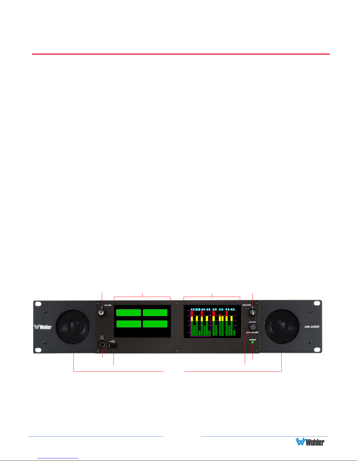
The front panel is shown in Figure 2-1.
Headphone
Jack
Figure 2–1: iAM-AUDIO-2 Front Panel
Level Meter DisplayVolume Menu / Option Display
USB
Main Menu
Audio
Preset
System
Information
Source
Select
System
Options
2
-00
-20 -20
-30
-40
-60
Speakers
9
10
14131615
11
7856341
12
S
S
S
t
t
t
e
r
u
r
e
d
e
r
i
o
e
o
o
A
2
B
Adjust / Aux Volume
S
t
u
d
i
o
7
-00
-30
-40
-60
Balance
Power
1. Speakers: Local near field audio monitoring is achieved through the use of class D
amplifiers. There are two (left/right) full range speakers. The speaker response
may be adjusted with tone controls. Refer to the Menu / Option Touchscreen
section of Chapter 2.
Page 10

2. Headphone Jack: A 1/4" jack for an optional headphone is provided on the front
panel. Speaker audio mutes when headphones are plugged in.
3. Volume: This controls the speaker and headphone output level for the monitoring
mix.
4. Balance: This controls the relative left/right levels for the stereo mixes. By default,
it controls loudspeaker and headphone output, though other options may be set in
the Web GUI preferences.
5. Adjust / Aux Volume: Turning this control right or left moves a white selection
box from channel to channel on the metering screen. Pressing the Adjust control
solos the selected channel. If a muted channel is selected with this control, it is
unmuted and soloed. Pressing the Adjust control again or touching the meter area
anywhere removes the channel solo. On units equipped with the Dolby Decode
option, if the Adjust control is used to select a Dolby channel, the Dolby Zoom
feature will activate and display the channels within the Dolby signal, as well as
Dolby metadata.
6. USB 2.0 Port: This USB Type A connector allows you to use a flash drive (not
supplied) to perform software updates and copy system configurations to another
iAM-AUDIO or to a PC. Software updates are controlled from the Web GUI.
7. Menu / Option Display: This touchscreen display is used for a limited amount of
setup and status display. The large majority of setup functions are performed using
the Web GUI.
8. Level Meter Display(s): High resolution bar graph meters appear here showing
the levels of up to 16 channels selected for monitoring. These are grouped into
clusters as specified in the Web GUI: mono clusters (1.0), pair clusters (2.0), or
surround sound clusters (5.1 or 7.1).
9. Power: This indicator lights green when the system is powered and ready for use.
A solid or blinking yellow color indicates that the product is starting up.
Page 11
Important:
The monitor and power adapter have been tested as a combined
Important:
Rear Panel
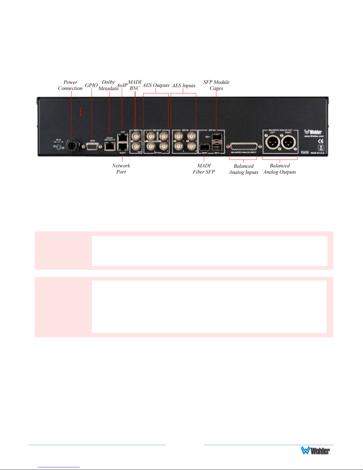
The rear panel is shown in Figure 2-2.
Figure 2-2: iAM-AUDIO-2 Rear Panel Layout
Power Connection: The iAM-AUDIO uses an external AC to 18 VDC power adaptor. A
locking DC connector for this power supply is provided on the rear panel. The AC inlet on
the adaptor is a standard IEC receptacle for 100 to 240 VAC ±10%, 50/60 Hz power
connection. Four regional AC power cords, supplied according to shipping region, are
available.
By design, the supplied AC mains power cord will only plug into a
three-prong grounded outlet for your safety. If the plug does not fit
into the outlet, contact an electrician to replace the obsolete outlet.
apparatus to verify compliance with applicable safety and
electromagnetic compliance standards. Use of another power adapter
provided by the user may negate the compliance or cause the
monitor to not perform properly. Wohler Technologies cannot accept
any responsibility for the outcome in such cases.
1. GPIO: (future implementation) This DB-9 connector provides 2 input pins
and 2 output pins to perform GPIO functions as defined by the Web GUI.
2. Network Port: This Ethernet port can connect to either a LAN or to a PC
to let you customize the iAM-AUDIO configuration remotely. The PC
running the Wohler Web GUI will also allow you to copy system
configurations from one iAM-AUDIO to another, as well as to update the
iAM-AUDIO software and firmware. The Wohler Web GUI is described in
Chapter 4 of this manual. Third party equipment, connecting to the iAM-AUDIO
via a LAN plugged into this port and using an API commands, can view and
change product options, as well. This API is described in Appendix D of this
Page 12

manual.
3. AoIP: This Ethernet port can accept either a Dante or a Ravenna Audio over
IP signal. An optional license key must be purchased to enable this function.
There are different hardware option cards for each signal and the appropriate
and desired capability must be specified at order.
4. MADI BNC: This COAX input accepts an AES10 64-channel signal at 48
kHz sample rate. An optional license key must be purchased to enable this
function. The COAX output is reclocked from the MADI source. When
power to the iAM-AUDIO is not present, the COAX input and output are
automatically connected together to allow the MADI signal to pass
through.
5. MADI Fiber SFP: (optional) This input module accepts an optical AES10
64-channel MADI input signal at 48 kHz sample rate. An optional license
key must be purchased to enable this function. The SFP fiber module may be
used in conjunction with the MADI BNC connectors to provide COAX to
fiber or fiber to COAX conversion. The outputs are reclocked. A software
license must be installed for SFP ports to function. Refer to the System
Setup section in Chapter 4 and to Figure 4-14 to install software licenses.
6. Dolby Metadata: (optional) This RJ-45 jack transmits metadata from
the selected Dolby bitstream in RS-485 serial data protocol. Refer to the
System Setup section in Chapter 4 and to Figure 4-14 to install software
licenses.
7. AES Out: By default, the AES OUT 1 BNC outputs the same mixed audio
as the XLR analog outputs, as heard from speakers or headphones, but as
an AES3id pair. This output is adjusted by the Volume control. Other
options may be set in the Web GUI. AES Out 1 is a standard feature on
the iAM-AUDIO products. The AES OUT 2, 3, and 4 connections are
reserved for possible future implementation.
8. AES In: These four BNC jacks accept AES3id digital audio pairs at a 48
kHz sample rate. An optional license key must be purchased to enable this
function. Channels are selected as AES 1-8.
9. SFP Module Cages: The two SFP cages are provided to accept one or two
optional SFP modules compatible with SDI coaxial or optical signals.
Single or dual transceiver arrangements are possible. The SFP modules
are hot swappable for convenience. An optional license key must be
purchased to enable each module. A software license must be installed for
an SFP port to function. Refer to the System Setup section in Chapter 4
and to Figure 4-14 to install software licenses. The following SFP modules
are offered:
a. 3G/HD/SD-SDI Single Video Receiver with Active Loopback:
This uses HD-BNC connectors.
b. 3G/HD/SD-SDI Video SFP with Optical Input: This uses LC
fiber connectors. It is a Single-Mode Receiver, Medium Haul, Non-
MSA, and no output.
Page 13
c. 3G-SDI Transceiver: This uses HD-BNC connectors. Input and
output are both SDI.
d. SMTPE 2022-6 Receiver: This uses Multi-Mode 850 NM, LC fiber
connectors. It allows the iAM- AUDIO to monitor SDI audio
transmitted in real time over Ethernet. You must use the emSET
configuration software to set up this option. It is available from
Wohler Technologies Technical Service.
e. SMTPE 2110 Receiver: This uses Multi-Mode 850 NM, LC fiber
connectors. It allows the iAM- AUDIO to monitor SDI audio
transmitted in real time over Ethernet. You must use the emSET
configuration software to set up this option. It is available from
Wohler Technologies Technical Service.
f. SMTPE 2110 or 2022-6 Receiver: This uses Multi-Mode 850 NM,
LC fiber connectors. It allows the iAM- AUDIO to monitor SDI audio
transmitted in real time over Ethernet. You must use the emSET
configuration software to set up this option. It is available from
Wohler Technologies Technical Service.
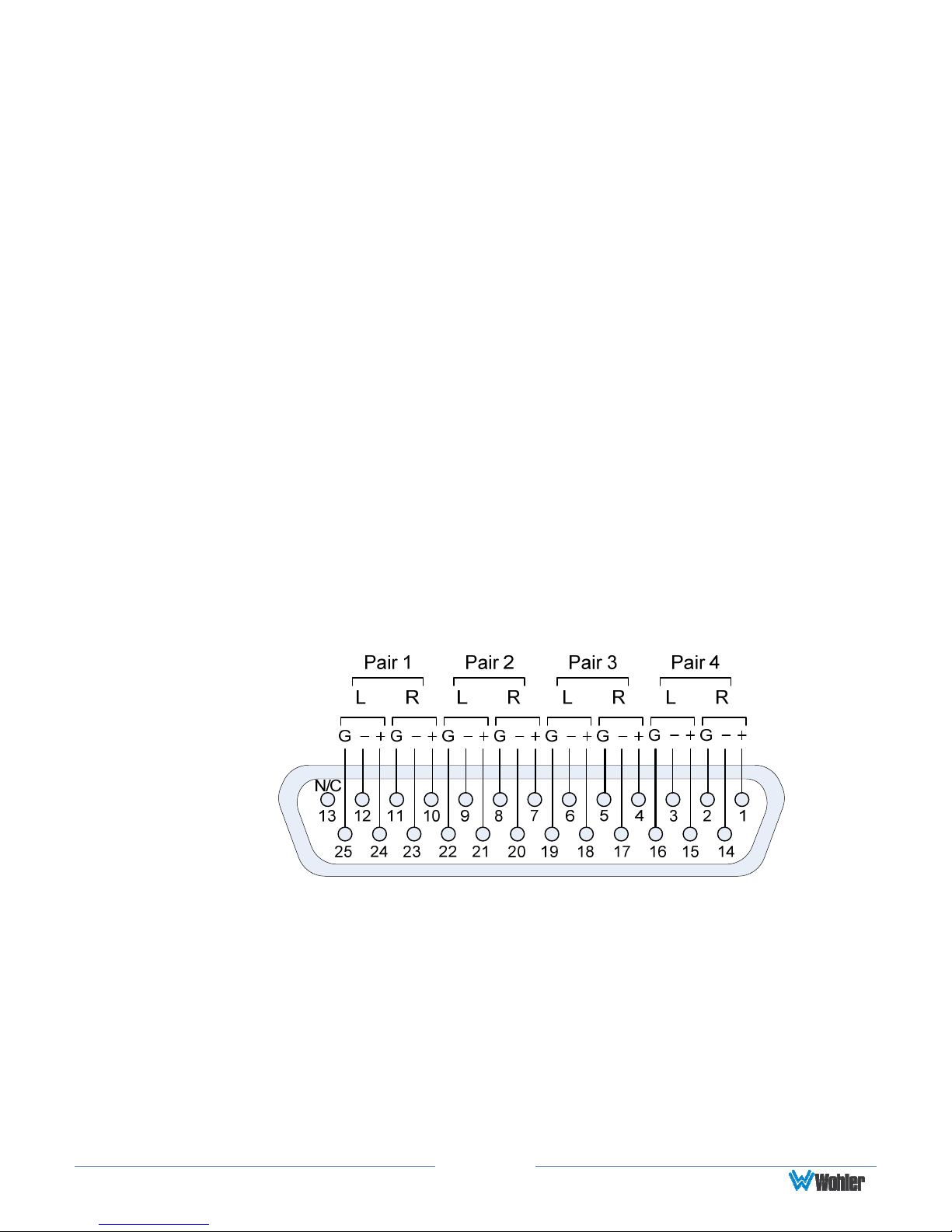
10. Analog Inputs: This DB-25 female connector accepts +10 dBu
broadcast level balanced audio. An optional license key must be purchased
to enable this function. Tascam cables may be used, and can be purchased
by contacting Wohler Sales. Refer to Figure 2-3 for the pinout of this
connector.
Figure 2-3: Analog DB25 Input Connections
Page 14
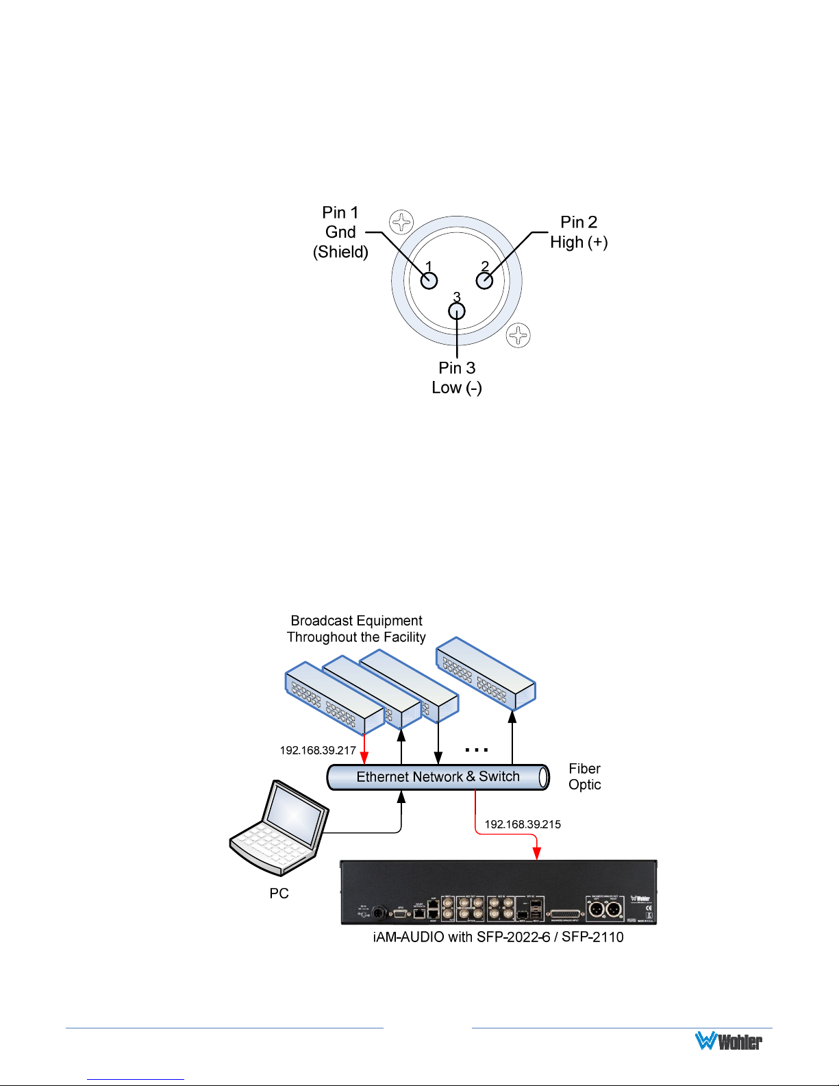
11. Analog Outputs: These male XLR connectors provide two balanced
analog outputs:
Left
and
Right
. The source of these signals is the mix of
audio as monitored by the internal speakers and is adjusted by the
Volume control. The Analog Outputs are standard on the iAM-AUDIO.
Refer to Figure 2-4 for the pinout of this connector.
Figure 2-4: Analog XLR Output Connections
SFP-2022-6 / SFP-2110 Address Setup
While the optional SFP-2022-6 and SFP-2110 modules monitor program audio
created from distinctly different technologies, both are connected to the network in
the same way and have the same requirements for addressing. Figure 2-5
illustrates the network connections they need.
Figure 2-5: SFP-2022-6 and SFP2110 Network Diagram
The optional SFP-2022-6 or SFP-2110 module furnished by Wohler Technologies is
manufactured by Embrionix and comes from the factory with a default IP address.
Page 15
Important:
The numbers
above each
meter
bar graph
position only indicate its
To integrate it into your digital network, you need to set its address to the source to
be monitored. You must use the emSET configuration software to set up this option.
It is available from Wohler Technologies Technical Service. The procedure to
accomplish this is described in the SFP-2022-6 / SFP-2110 Setup Guide (part
number 821822), which is available at https://www.wohler.com/wp-
content/uploads/2016/09/SFP-2022-6-SFP-2110-Setup-Guide-821822A.pdf
Channel Meters and Touch Operations
The audio mixer terminology of “solo” is used in this manual when referring to
muting all but a specific audio channel or subgroup. Since the terms “group” and
“subgroup” have different meanings in SDI vs. pro audio, this manual uses the term
“cluster” to define a set of audio channels forming an audio program—such as Mono
(1.0), Stereo (2.0) or Surround (5.1 or 7.1).
relative position on the display, and not any particular channel number.
Meter numbers only serve as references for monitor configurations at
the Web GUI level. Different presets typically have different input
channels assigned to various meters.
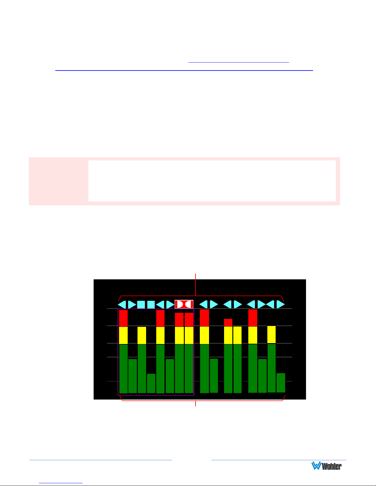
Audio meters are displayed on touchscreen LCD display(s) in labeled clusters, as
shown in Figure 2-6. The clusters of channels and other options relating to this are
defined using the iAM-AUDIO Web GUI software as described in Chapter 4.
Figure 2-6: Audio Level Meter Screen
Channel Identifiers
9
3
1
-00
-20 -20
-30
-40
-60
2
5
6
4
87
S
t
u
d
i
o
2
10
11
S
t
e
r
e
o
A
Channel / Cluster Touch Selection Area
1. Channel Identifiers: Above the level meters are the Channel Identifiers.
They indicate the following:
12
13
S
t
r
e
r
e
o
B
14
15
16
S
-00
t
u
d
i
-30
o
-40
7
-60
Page 16

An arrow pointing to the left indicates that this is a left channel and
1
will be monitored in the left speaker.
2
An arrow pointing to the right indicates that this is a right channel
and will be monitored in the right speaker.
3
A square indicates that this is a center channel and will be monitored
in both speakers.
The symbol shown on channels 7 and 8 in Figure 2-6 indicate that
87
this channel pair is a Dolby bitstream. Refer to the Dolby Zoom
section of this chapter.
The channel numbers within the symbols indicate the numbered position
in the meter display, not the channel position within the monitored
stream. Channel assignment is made in the Configure Presets page of
the Web GUI.
2. Channel / Cluster Touch Selection Area: Touching the meters of a
cluster will let you mute, un-mute, or solo the associated channel(s).
Colored boxes surrounding the cluster or channel indicate what operation
is being performed. The following describes each function:
a. Mute / Un-Mute Selection: A violet box surrounds any channel
cluster that is muted. Typically, when the iAM-AUDIO is first
powered or when a preset is changed, all of the channel clusters
are muted. Touching a muted channel cluster un-mutes it and
removes the violet box. Muting and un-muting by touching is an
alternate action function.
b. Solo Selector: Touch for two seconds any channel cluster you
would like to solo. A blue box will then surround the cluster and
that will be the only cluster you hear. Any violet boxes will
disappear. Touch again to return the combination of monitored
clusters to the way they were before you soloed the cluster.
c. Channel Solo: Rotating the Adjust control will move a white
selection box from channel to channel. Press the Adjust control to
solo the selected channel. That channel alone will then be
surrounded by a blue box and it will the only channel being
monitored. Press the Adjust control again or touch anywhere on
the meters to undo the solo and return the combination of
monitored clusters to as it was before you soloed the channel.
Dolby Zoom Screen
Dolby Zoom is a very powerful analysis tool. Much as a camera lens can "zoom"
into a single subject of interest out of many, the Dolby Zoom feature lets you
quickly "zoom" into a single Dolby bitstream, out of multiple encoded Dolby
streams and other channels. You can immediately listen to and meter the contained
audio channels, as well as view the Dolby metadata. Bitstreams are shown
distinctively along with the normal metering channels, as shown in Figure 2-6. The
Page 17
Dolby Zoom Screen is shown in Figure 2-7.
Dolby decoding is an optional feature requiring the OPT-DOLBY module. It
allows decoding and monitoring of Dolby® D, DD+, & E streams.
Refer to the
System Setup section in Chapter 4 and to Figure 4-14 to install software licenses.
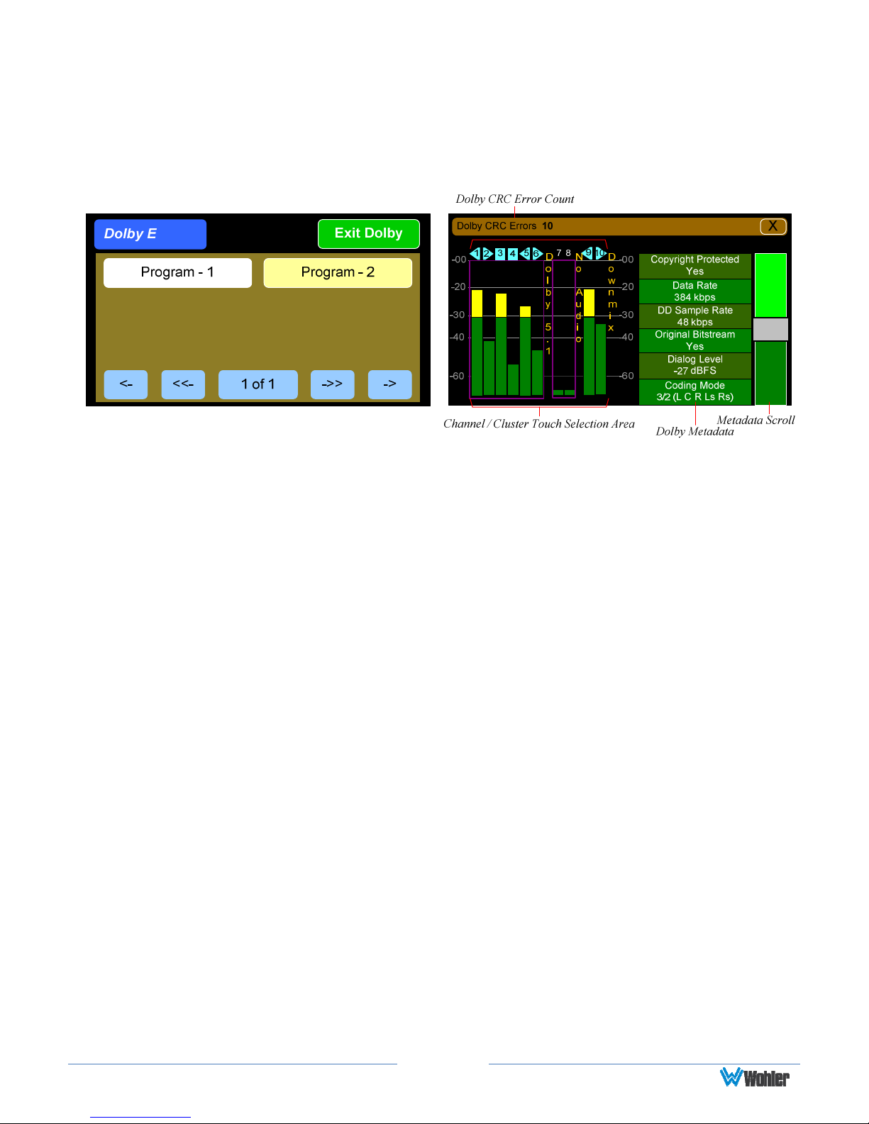
Figure 2-7: Dolby Zoom Screen
When the Dolby Zoom screen appears, the speakers will automatically begin
monitoring the downmix audio. However, you may solo or mute the individual
channels for troubleshooting or other purposes. Use the left screen to select other
Dolby E channels to be monitored. Touch and slide the control on the Dolby
Metadata screen to scroll through multiple lines of metadata.
The Dolby Zoom screen also displays Dolby CRC (Cyclic Redundancy Check)
Errors, which are automatically totaled. Touching the "X" on the Dolby Error Count
display, resets the count. The maximum count is 65,535 and it will roll over to 0
and restart counting if this is exceeded. CRC Errors are an indication that the Dolby
signal is being disrupted, either by intermittent network issues or poor wiring.
Occasional errors probably cannot be heard, but this is a diagnostic tool that lets
you measure the extent of the problem, if any.
Touching the Exit Dolby button returns you to the monitoring screen from which
you came.
Page 18
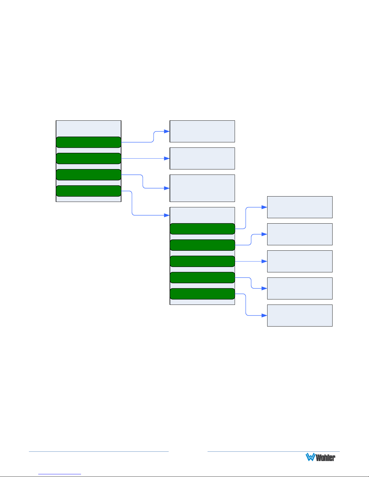
Menu / Option Touchscreen
By far, most of the option settings are performed using the Web-based GUI
software. However, there are a few commonly used setting and information
screens that are available locally in the iAM-AUDIO using the Main Menu which
appears on the left screen. Figure 2-8 is a diagram of the menu arrangement, a
tree showing how to reach any menu from the Main Menu. Figure 2-9 shows the
Main Menu.
Figure 2-8: Menu Tree
Main Menu
Audio Preset
Source Select
System Information
System Options
Audio Preset
Select Screen
Source Selection
Screens
System
Information
Screen
System Options
Network Settings
Speaker Options
System Update
Factory Reset
System Reboot
Network Settings
Screen
Speaker Options
Screen
Software Upgrade
Screen
Factory Reset
Screen
System Reboot
Screen
Page 19
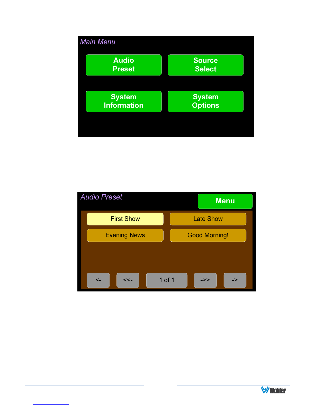
Figure 2-9: Main Menu
Audio Preset
Touch the Audio Preset button to display the Audio Preset menu as shown in
Figure 2-10.
Figure 2-10: Audio Preset Menu
Using this screen, the operator can quickly select the needed set of sources to
monitor as well as their arrangement on the metering screens. An example of this
screen is shown in Figure 2-10. If you have not set up any Presets, use the
Configure Presets page in the Web GUI to do so. Or, if you prefer not to set up
Presets, simply monitor the sources directly using the Source Select button in the
Main Menu.
1. The currently selected Preset is shown in yellow. To select a new preset,
touch one of the darker Preset buttons. The button will highlight in yellow
and the new Preset will be in effect.
Page 20
2. If there are more presets than will fit on this menu, touch the scrolling
buttons at the bottom of the screen to locate the Preset you are looking for.
To exit this menu and return to the Main Menu, touch the Menu button.
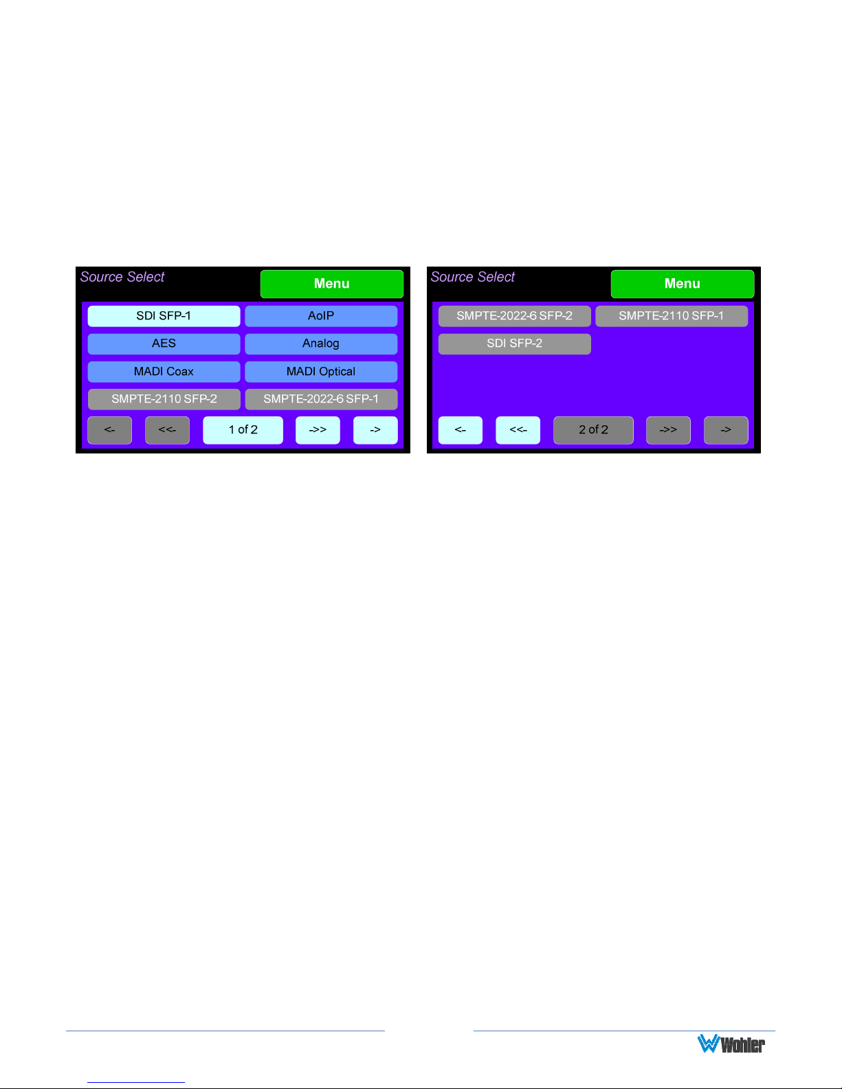
Source Select
Touch the Source Select button to display the Source Select screens as shown in
Figure 2-11.
Figure 2-11: Source Select Screens
Using this screen, the installer can quickly determine that the sources are correctly
connected and are ready for use. It allows you to directly monitor each selected
source.
1. The most recently selected source is shown in light blue.
2. Sources that the iAM-AUDIO is equipped to monitor are shown in blue.
3. Sources that the iAM-AUDIO is capable of monitoring, but are not licensed for
monitoring are shown in gray. If you would like to license additional signals,
contact Wohler to purchase the source module and/or license.
To select a source, simply touch the associated button. After a quick 2-second
delay, the metering screens will show the channels contained in that source, and
the Main Menu will reappear. The channels will be muted. Touch the channels you
would like to hear on the metering screen.
There are several pages of source selections. To flip between them, use the arrow
buttons at the bottom of the screens. To exit this menu and return to the Main
Menu, touch the Menu button.
If the source contains more than 16 channels, an additional selection screen will
appear so that you can further narrow your selection to a particular range of 16
channels. An example of this screen is shown in Figure 2-12.
Page 21
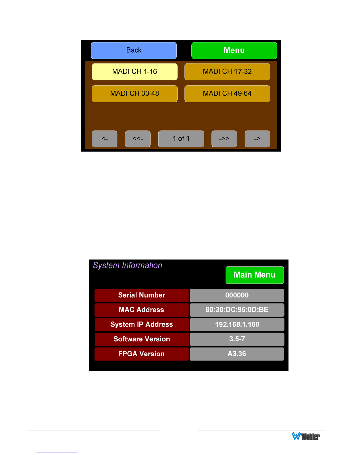
Figure 2-12: Select the 16 Channels to be Monitored
To return to the Source Select screen without making a channel range selection,
touch the Back button. To exit this menu and return directly to the Main Menu,
touch the Menu button.
System Information
Touching the System Information button displays the System Information
screen as shown in Figure 2-13. This screen lets you view the product Serial
Number, the MAC Address, the System IP Address, and the Software Version.
Figure 2-13: System Information Screen
The information shown on this screen is read only and cannot be changed.
Touch the Main Menu button return to the Main Menu.
Page 22

System Options
Touch the System Options button displays the System Options menu as shown
in Figure 2-14. This screen is an access point to the Network Settings, Speaker
Options, and Factory Reset screens.
Figure 2-14: System Options Menu
Network Settings
Touch the Network Settings button displays the Network Settings menu as
shown in Figure 2-15. This screen lets you view or change the product IP, the Net
Mask, Gateway and DNS. It also lets you switch between a static (fixed) or a
dynamic (DHCP) network address.
Figure 2-15: Network Settings Menu
1. To change the IP Address, Net Mask, Gateway, or DNS, tap the item you
would like to change. A keypad will appear, as shown in Figure 2-16.
Page 23

Important:
Figure 2-16: Network Configuration: Setting Change
2. Touch the digits to be entered and then touch the Enter button. The Clear
button may be touched to erase any mistyped digits.
3. Now repeat steps 1 and 2 until you have replaced all of the necessary digits.
4. To save the newly entered address(es), touch the Enter button. Touch the
Cancel button to return to the previous screen without saving any changes.
There is no confirmation for Save, so make sure you want to perform
this action before taking it. The system does not need to reboot before
it is once again ready for operation.
To change from a static (fixed) to a dynamic (DHCP) network address, touch the
DHCP button. The screen will change, as shown in Figure 2-17. To change back to
a static (fixed) network address, touch the DHCP button again. The colors of the
buttons will return to the ones depicted in Figure 2-15.
Figure 2-17: Network Settings: DHCP
Page 24

Important:
The system will not need to reboot before it
1. To complete the network addressing scheme change, touch the Save button.
This will save the changes you selected.
2. Touch the Cancel button to return to the previous screen without saving any
changes.
There is no confirmation for Save, so make sure you want to perform
this action before taking it.
is once again ready for operation.
Speaker Options
Touching the Speaker Options button on the Main Menu displays the Speaker
Options screen as shown in Figure 2-18. The controls on this screen affect various
characteristics of the monitored audio as heard on the iAM-AUDIO. The adjustments
made on this screen are not saved with each preset. Note that setting changes
made here will reflect on similar settings made using the Web GUI.
Figure 2-18: Speaker Options
The controls function as follows:
1. Speakers: This setting controls whether the monitor speakers are muted
while a headset plug is inserted into the headset jack on the front panel.
2. Low Cut: Low Cut is provided for cases where unusually deep content
produces audible distortion and interferes with monitoring.
3. Treble: This tone control adjusts the high frequency speaker audio response
from -12 dB to +12 dB. Lowering Treble compensates for high frequency
pre-emphasis or removes sibilance effects. Increasing Treble will add
“sizzle” to the sound and bring high-pitched sounds out of the mix. The
control can be touched and moved left or right to adjust in 1 dB increments.
Alternatively, after touching the control, the Adjust knob can be used to
Page 25

more critically adjust the setting.
4. Bass: This tone control adjusts the low frequency speaker audio response
from -12 dB to +12 dB. Lowering Bass will unmask midrange band sounds,
while increasing Bass will make the sound “fatter”. The control can be
touched and moved left or right to adjust in 1 dB increments. Alternatively,
after touching the control, the Adjust knob can be used to more critically
adjust the setting.
5. Set to Flat: This button sets both the Treble and Bass controls to 0 dB,
removing any emphasis or de-emphasis they can provide. Selecting Flat
provides the flattest measured response from the internal speakers.
6. Delay: The speaker audio can be delayed from 0 to 170 mS to synchronize
with video delays, when necessary. The control can be touched and moved
left or right to adjust in 1 dB increments. Alternatively, after touching the
control, the Adjust knob can be used to more critically adjust the setting.
The monitored audio changes dynamically as the setting is adjusted, which
allows audible and visual synchronization with video monitored on another
product.
Touch Main Menu to exit this screen.
System Update
Touching the System Update button displays Software Upgrade screen as
shown in Figure 2-19, showing the current software version of the product. To
update the system software locally from the iAM-AUDIO front panel, follow the
procedure in the Local Update from the Front Panel section of Appendix A.
Figure 2-19: Software Upgrade Screen
Page 26
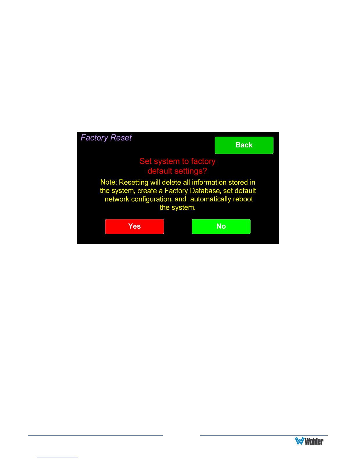
Factory Reset
Touching the Factory Reset button displays the Factory Reset screen as shown in
Figure 2-20. Because of the large change this function is about to make to the
product, it asks for you for verification that you really want to proceed.
The Factory Reset function should be used with caution. It deletes all of the
settings you have programmed into the system. It returns the system to the way it
was when received new from the factory. After using this function, you will need to
use the Wohler Web GUI to reprogram everything from the start or else import a
Database or the Presets that you previously saved using the Web GUI. Refer to the
Database Management section of Chapter 4.
Figure 2-20: Factory Reset
Note: Factory Reset will also reset your IP address to the default one (Static IP:
192.168.1.100/Gateway: 192.168.1.1/Netmask: 255.255.255.0) and clear the
database of Presets.
If you have any doubt as to whether you should press Yes, press Back or No
instead, and contact Wohler Technical Service for advice. Pressing Back or No will
return you to the System Options menu.
Page 27

System Reboot
Touching the System Reboot button displays the System Reboot screen as
shown in Figure 2-21. This function is normally only used upon request from Wohler
Technical Service to troubleshoot or correct an issue.
The System Reboot function should be used with a bit of caution. It puts the
system out of service for several minutes while it is rebooting.
Figure 2-21: System Reboot
If you have any doubt as to whether you should press Yes, press Back or No
instead, and contact Wohler Technical Service for advice. Pressing Back or No will
return you to the System Options menu.
Page 28

16 channels from:
CHAPTER 3:
Table 3–1: iAM-AUDIO-2 Specifications
Specification
Power Requirements
Power Consumption 40 Watts
Dimensions
(H x W x D)
Weight 10.4 lbs. (4.7 kg)
Supplied Accessories Power Adapter, AC Power Cord
Display Type LCD
Number of Displays 2
Screen Resolution 800H x 480V
Level Meters Simultaneous VU & PPM
Level Meter Scale Digital Scale
Technical Info
100 VAC to 240 VAC ± 10%, 50/60Hz
3.5” x 19” x 7.5” (88mm x 483mm x
191mm), standard 19” rack mounting
Values/Domains
Sample Rate 48kHz
De-Multiplexing
• 16-channel SD/HD/3G-SDI
• 64-channel AES10 MADI
•
1 or 2 SDI Inputs or Outputs
Optional – Single SFP Transceiver:
• HD-BNC Coax 3G/HD/SD-SDI
SDI Inputs / Outputs
• Multi-Mode Fiber: 1 SI Optical
SC-Connector, 1300nm
• Single-Mode Fiber: 1 SI Optical SC
Connector, 1310nm
•
1 MADI BNC, Standard Coax I/O
Optional – SFP Transceiver:
MADI Inputs / Outputs
• Multi-Mode Fiber: 1 MADI Optical
SC-Connector, 1300nm
• Single-Mode Fiber: 1 MADI Optical
SC Connector, 1310nm
Optional - SFP Receiver:
SMPTE 2022-6 Receiver
• Multi-Mode Fiber: LC Connectors,
Optional - SFP Receiver:
SMPTE 2110 Receiver
• Multi-Mode Fiber: LC Connectors,
850nm
850nm
Cable/Fiber Length (max)
COAX (such as Belden 1694A): > 150 m
Multi-mode fiber: 1 km
Single-mode fiber: 10 km
Page 29
 Loading...