

Page 1

iAM2-8
2RU Multi-Channel Audio Monitor
User Guide
Part Number 821834, Revision D
Page 2

© 2023 Wohler Technologies, Inc. All rights reserved.
This publication is protected by federal copyright law. No part of this publication may be copied or
distributed, stored in a retrieval system, or translated into any human or computer language in any
form or by any means electronic, mechanical, manual, magnetic, or otherwise, or disclosed to third
parties without the express written permission of Wohler Technologies.
Reproduction
Licensed users and authorized distributors of Wohler Technologies, Inc. products may copy this
document for use with Wohler Technologies., Inc. products provided that the copyright notice above
is included in all reproductions.
Customer Support
Wohler Technologies, Inc.
1280 San Luis Obispo Ave
Hayward, CA, 94544
Phone: 510-870-0810
Web: www.wohler.com
Sales: [email protected]
Support: [email protected]
Disclaimers
Even though Wohler Technologies, Inc. has tested its equipment and software, and reviewed the
documentation, Wohler Technologies, Inc. makes no warranty or representation, either express or
implied, with respect to software, documentation, their quality, performance, merchantability, or
fitness for a particular purpose.
In no event will Wohler Technologies, Inc. be liable for direct, indirect, special, incidental, or
consequential damages resulting from any defect in the hardware, software, or its documentation,
even if advised of the possibility of such damages.
Some states do not allow the exclusion or limitation for incidental or consequential damages, so the
above exclusion or limitation may not apply to you.
PDF
All text strings appearing in this shade of blue are hyperlinks.
Other Technologies and Products
Google Chrome is a registered trademark of Alphabet Inc.
Microsoft Windows and Internet Explorer are registered trademarks of Microsoft Corporation.
Dante and Brooklyn are registered trademarks of Audinate Pty Ltd.
Ravenna is a registered trademark of ALC NetworX GmbH.
ZMAN and Aneman are registered trademarks of Merging Technologies.
All product names, logos, and brands are property of their respective owners. All company, product
and service names used in this document are for identification purposes only. Use of these names,
logos, and brands does not imply endorsement.
Last Update
March 6, 2023
Page 2
iAM2-8
Page 3

TABLE OF CONTENTS
Table of Contents
User Guide ........................................................................................ 1
TABLE OF CONTENTS .......................................................................... 3
Table of Contents ........................................................................................... 3
CHAPTER 1: Installation ....................................................................... 7
Introduction .................................................................................................. 7
Overview ............................................................................................ 7
Safety .......................................................................................................... 7
Instructions ......................................................................................... 7
Safety Symbols.................................................................................... 8
Mounting............................................................................................. 8
Heat Dissipation ................................................................................... 8
Sympathetic Vibration........................................................................... 9
Mechanical Bracing ............................................................................... 9
Electrical Interference ........................................................................... 9
Power ................................................................................................. 9
Compliance ................................................................................................... 9
FCC .................................................................................................... 9
ICES-003 ............................................................................................ 9
CHAPTER 2: Local Operation............................................................... 10
Operation.................................................................................................... 10
Startup....................................................................................................... 10
Front Panel.................................................................................................. 10
Rear Panel................................................................................................... 12
SFP-2022-6 / SFP-2110 Address Setup............................................................ 17
Channel Meters and Touch Operations............................................................. 18
Dolby Zoom Screen ...................................................................................... 21
Menu / Option Touchscreen ........................................................................... 22
Main Menu ........................................................................................ 23
Unit Settings ..................................................................................... 23
Speaker Options................................................................................. 24
Meter Scales...................................................................................... 25
Unit Configuration .............................................................................. 27
Phase Configuration............................................................................ 28
Analog Configuration .......................................................................... 29
Source Select .................................................................................... 30
Presets ............................................................................................. 31
Preset Favorites ................................................................................. 32
All Presets ......................................................................................... 33
Loudness Meter.................................................................................. 34
Loudness Settings .............................................................................. 36
System Options Menu ......................................................................... 37
iAM2-8
Page 3
Page 4

Network Settings................................................................................ 38
System Reboot .................................................................................. 40
System Update .................................................................................. 41
Factory Reset .................................................................................... 42
System Details................................................................................... 43
Passcode Settings .............................................................................. 44
Forgotten Passcode ............................................................................ 46
CHAPTER 3:
Technical Info ............................................................... 47
CHAPTER 4: The iAM2-8 Web GUI ....................................................... 52
Web Browser / Control Device........................................................................ 52
First Time IP Assignments ............................................................................. 52
Peer-to-Peer Connection...................................................................... 52
Network Connection............................................................................ 53
Network Setup............................................................................................. 54
Dashboard .................................................................................................. 55
Audio Meters ............................................................................................... 59
System Preferences...................................................................................... 60
System Audio Clock Reference ............................................................. 60
Loudness Configuration Tab ................................................................. 61
Phase Indicator Configuration Tab......................................................... 62
Front Panel Configuration Tab .............................................................. 63
Preset Management...................................................................................... 65
Dolby Presets .............................................................................................. 70
Output Routing ............................................................................................ 71
Destination Outputs............................................................................ 72
Source Inputs .................................................................................... 72
Output Options .................................................................................. 73
Typical Questions Regarding Output Routing .................................................... 73
What signal outputs can be controlled using the Output Routing feature? ... 73
How do the outputs behave if I do not purchase OPT-OUTPUT-ROUTING
license? ............................................................................................ 73
What is the difference between Global Output Routing and Output Routing in
Presets?............................................................................................ 74
How do I route whatever is being monitored to the XLR and AES outputs?.. 74
How do I have a downmixed pre-fade output on AES Pair-1 combined with a
post-fade output on the Analog XLRs? ................................................... 74
How do I make the XLR outputs follow the Audio Meter screen solos & mutes
while the AES Pair-1 does not? ............................................................. 75
How do I route only specific monitored channels to the Analog XLR outputs?
....................................................................................................... 76
The optional Global Output Routing feature works great. But what if we don't
want to create any Presets and want to monitor audio only using Source
Select? How would I configure different outputs for Source Select choices?. 76
How do I keep the internal speakers muted and have audio only on the
analog XLR outputs? ........................................................................... 76
How do I ensure that the outputs are automatically muted when the
Headphone jack is inserted?................................................................. 77
What are AoIP-Pair 9 and AoIP Pair 10? ................................................. 77
How do I ensure that my outputs are pre-faded but follow the solo-mutes on
the web interface? This will allow us to monitor only the unmuted/solo Audio
Meter channels on amplified stereo speakers connected to the Analog XLR’s.
....................................................................................................... 78
iAM2-8
Page 4
Page 5

Preset Replication......................................................................................... 78
Import/Export Presets................................................................................... 80
Export Configuration ........................................................................... 80
Import Configuration .......................................................................... 81
System....................................................................................................... 83
System Information............................................................................ 83
SFP Information ................................................................................. 84
Licenses............................................................................................ 85
Factory Reset .............................................................................................. 86
Reboot System ............................................................................................ 87
APPENDIX A: Software Upgrades......................................................... 88
Introduction ................................................................................................ 88
Download the Software ................................................................................. 88
Update Methods........................................................................................... 88
Local Update from the Front Panel .................................................................. 89
Updating via the Web GUI using a Flash Drive .................................................. 91
Updating an iAM2-8 Remotely ........................................................................ 93
Updating Multiple Units Remotely ................................................................... 95
APPENDIX B: Dante Network Setup ..................................................... 98
Introduction ................................................................................................ 98
What is in the iAM2-8 for Dante? .................................................................... 98
DanteTM Device Setup ..................................................................................100
Dante Clock Selection ..................................................................................101
Channel Names...........................................................................................101
AES67 .......................................................................................................102
Device Lock................................................................................................104
Dante Firmware Upgrades ............................................................................104
Additional Information .................................................................................105
DanteTM Legal Disclosures.............................................................................105
APPENDIX D: Ravenna (ZMAN) Setup .................................................106
Introduction ...............................................................................................106
What is in the iAM2-8 for Ravenna? ...............................................................106
RAVENNA-Compatible Talker/Listener...................................................106
AVB Ethernet Features .......................................................................106
Configuring the AOIP Merging Option Card......................................................107
Getting Started | General Settings .......................................................108
Getting Started | PTP .........................................................................109
Getting Started | Session Sources........................................................110
Getting Started | Session Sinks ...........................................................111
Getting Started | Session Info .............................................................112
Getting Started | Ins/Outs ..................................................................113
Getting Started | I/O Router ...............................................................113
Operation: .................................................................................................114
Connecting Remote Source to Local Sink ..............................................114
ZMAN Session Sinks ..........................................................................114
ZMAN Session Sources .......................................................................116
ZMAN Updating .................................................................................116
Page 5
iAM2-8
Page 6

APPENDIX E: API Documentation .......................................................117
Introduction ...............................................................................................117
API: Presets ...............................................................................................117
APPENDIX F: Out of Band Control.......................................................130
Introduction ...............................................................................................130
SFP IP Address Configuration ........................................................................130
SFP System Configuration ............................................................................131
SFP 2110 Configuration................................................................................132
SFP 2110 Preset Config ................................................................................135
Diagnostic Information.................................................................................136
Page 6
iAM2-8
Page 7

Important:
CHAPTER 1: Installation
Introduction
Overview
The iAM2-8 is a 2RU multi-channel multi-source audio monitor with basic 3G-SDI
and analog inputs. It may also be purchased with a large variety of other inputs or
these may be added later at the need arises. Refer to the Specifications section of
this manual or contact Wohler Sales for more information.
The iAM2-8 is compact and simple to operate, with straightforward controls. It has
two touch screen LCD displays providing up to 8 high resolution level meters and
Loudness meters. Any channels (or channel pairs) from any audio/video source
stream may be monitored.
The iAM2-8 includes two 3G SDI inputs and it can monitor audio from them.
Optional modules will allow decoding of an additional SDI input, Dolby, MADI,
AES3, Dolby D, DD+, E, SMPTE 2110, SMPTE 2022-6, and AES streams. It contains
APIs for remote management.
Setups are created and configured using local menus and a web browser over a
network connection to the integral web server of the iAM2-8. The web server will
also allow you to view the audio meters remotely.
Safety
Instructions
1. Read, keep, and follow all of these instructions; heed all warnings.
2. Do not use this equipment near water.
3. Use only a dry cloth to clean the equipment.
4. Do not block any ventilation openings.
5. Do not install near any heat source such as a radiator, heat register, amplifier, or
stove.
6. Do not attempt to plug the unit into a two-blade outlet (with only two prongs of
equal width).
By design, the supplied AC mains power cord will only plug into a
three-prong grounded outlet for your safety. If the plug does not fit
into the outlet, contact an electrician to replace the obsolete outlet.
7. Protect the power cord from being walked on or pinched, particularly at plug
connection on the equipment and at the socket.
8. Use only the attachments/accessories specified by the manufacturer.
9. Unplug the equipment during lightning storms or when unused for long periods
iAM2-8
Page 7
Page 8
WARNING:
avoid personal injury.
of time.
10. Refer all servicing to qualified service personnel. Servicing will be required
under all of the following conditions:
a. The equipment has been damaged in any way, such as when the power-
supply cord or plug is damaged.
b. Liquid had been spilled or objects have fallen onto the equipment.
c. The equipment has been exposed to rain or moisture.
d. The equipment does not operate normally.
e. The equipment has been dropped.
Safety Symbols
The symbol to the left warns of electric shock hazard inside the unit.
Disconnect the power cord before removing access panels when
installing upgrades. Only qualified service personnel are to operate
the equipment with covers removed, and are to exercise caution to
Mounting
The unit is designed for a standard 19" rack. Install it at ear/eye level for best high
frequency response and visual observation of the display screens. Please adhere to
the following clearances:
Table 1-1: Clearance Recommendations
Clearance
Heat Dissipation
The ambient temperature inside the mounting enclosure should not exceed 40°
Celsius (104° Fahrenheit). Adjacent devices can be rack mounted (or stacked) in
proximity to the unit if this temperature is not exceeded. Otherwise, allow a 1RU
(1.75”/44.45mm) space above and below the unit for air circulation.
Surface
24” Front
3” Rear
2” Sides
1.75” Top and Bottom (if either radiates heat)
0” Top and Bottom (if no heat)
Important
iAM2-8
Heat generated by the class D power amplifiers, power supplies,
and other components is vented by slots in the sides and back of
the unit. Therefore, as a safety precaution, you must allow proper
ventilation on these surfaces.
Page 8
Page 9

Sympathetic Vibration
Sympathetic vibration from other equipment (cables, etc.) in the rack may be
serious enough to interfere with the unit’s sound quality. If you experience
sympathetic vibrations, use thin card stock, felt, foam, or weather-stripping
between the vibrating surfaces. Tie loose cables securely with cable ties.
Mechanical Bracing
The 2RU chassis is securely attached to the front panel. In addition, the chassis has
mounting tabs through which you attach it to the rack rail. This feature will reduce
or eliminate rear bracing requirements in many mobile/portable applications. The
weight of internal components is distributed fairly evenly around the unit.
Electrical Interference
Be careful to avoid mismatched cable types and other similar causes of undesired
reflections in digital signal systems. If severe enough, such reflections can result in
corruption of the digital data stream. As with any audio equipment, maximum
immunity from electrical interference requires the use of shielded cable; however,
satisfactory results can sometimes be obtained without it. The internal circuitry
ground is connected to the chassis.
Power
The unit connects to an AC mains power source (100 to 240 VAC, 65W, 50/60Hz)
using an IEC power cord.
When the mains plug or appliance coupler is used as the disconnect device, the
disconnect device should remain operable.
Compliance
FCC
This equipment has been tested and found to comply with the limits for a Class A
digital device, pursuant to part 15 of the FCC Rules. These limits are designed to
provide reasonable protection against harmful interference when the equipment is
operated in a commercial environment. This equipment generates, uses, and can
radiate radio frequency energy and, if not installed and used in accordance with the
instruction manual, may cause harmful interference to radio communications.
Operation of this equipment in a residential area is likely to cause harmful
interference, in which case users will be required to correct the interference at their
own expense.
ICES-003
This Class A digital apparatus complies with Canadian ICES-003.
Cet appareil numérique de la classe A est conforme à la norme NMB-003 du
Canada.
Page 9
iAM2-8
Page 10
CHAPTER 2: Local Operation
Operation
The iAM2-8 can be operated easily and simply from controls on its front panel, as
described in this chapter. It may be accessed remotely in two ways, via the Wohler
Web GUI for administrative purposes or by third party equipment via Application
Programming Interface (API) commands. The Wohler Web GUI is described in
Chapter 4 of this manual. The API commands are described in Appendix E of this
manual.
Startup
The iAM2-8 will begin its startup process when it is connected to power. There is no
power switch. It is normal for the product to require about 45 seconds to start up
and be ready to use.
When the iAM2-8 completes its startup, the Status indicator will turn green.
Depending upon optional settings, all channel pairs will either be in the muted
condition or set in a predetermined way. You may then use the Source and
Channel controls to enable only the program channels you want to hear.
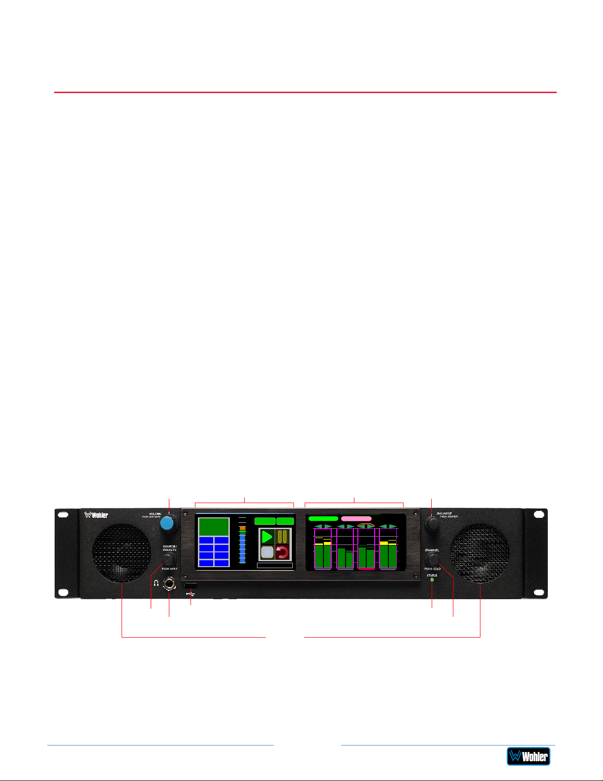
Front Panel
The front panel is shown in Figure 2-1.
Volume
Source
Headphone
Jack
Figure 2–1: iAM2-8 Front Panel
Loudness
-22.5
LKFS
LRA 0.1
PROG -21.5
MAX -20.1
TP -20.0
HD/720p/50HzSDI-1
+6
+3
-24
Ref
-3
-6
-9
-12
-15
-18
-21
LU-M
Audio Meters
1: Stereo 2.0 #1
Menu
+9
USB Status
Speakers
Audio Meter Screen
LKFS-M : -24.6
-00
-20
-30
-40
-60
1
SDI-1
587
4
2
3
S
S
t
t
e
e
r
r
e
e
o
o
Balance
6
-00
S
S
t
t
-20
e
e
r
r
-30
e
e
-40
o
o
-60
Channel
iAM-AUDIO
8 CHANNEL
1. Loudness Screen: A 4.3” LCD touch screen allows monitoring of Loudness
simultaneously with the audio meters.
2. Audio Meter Screen: A 4.3” LCD touch screen allows monitoring high resolution
bar graph meters of up to 8 channels.
Page 10
iAM2-8
Page 11
3. Speakers: Local near field audio monitoring is achieved through the use of class D
amplifiers. There are two (left/right) speakers. The speaker response may be
adjusted with tone controls in the Speaker Options menu. Refer to the Menu /
Option Touchscreen section of Chapter 2.
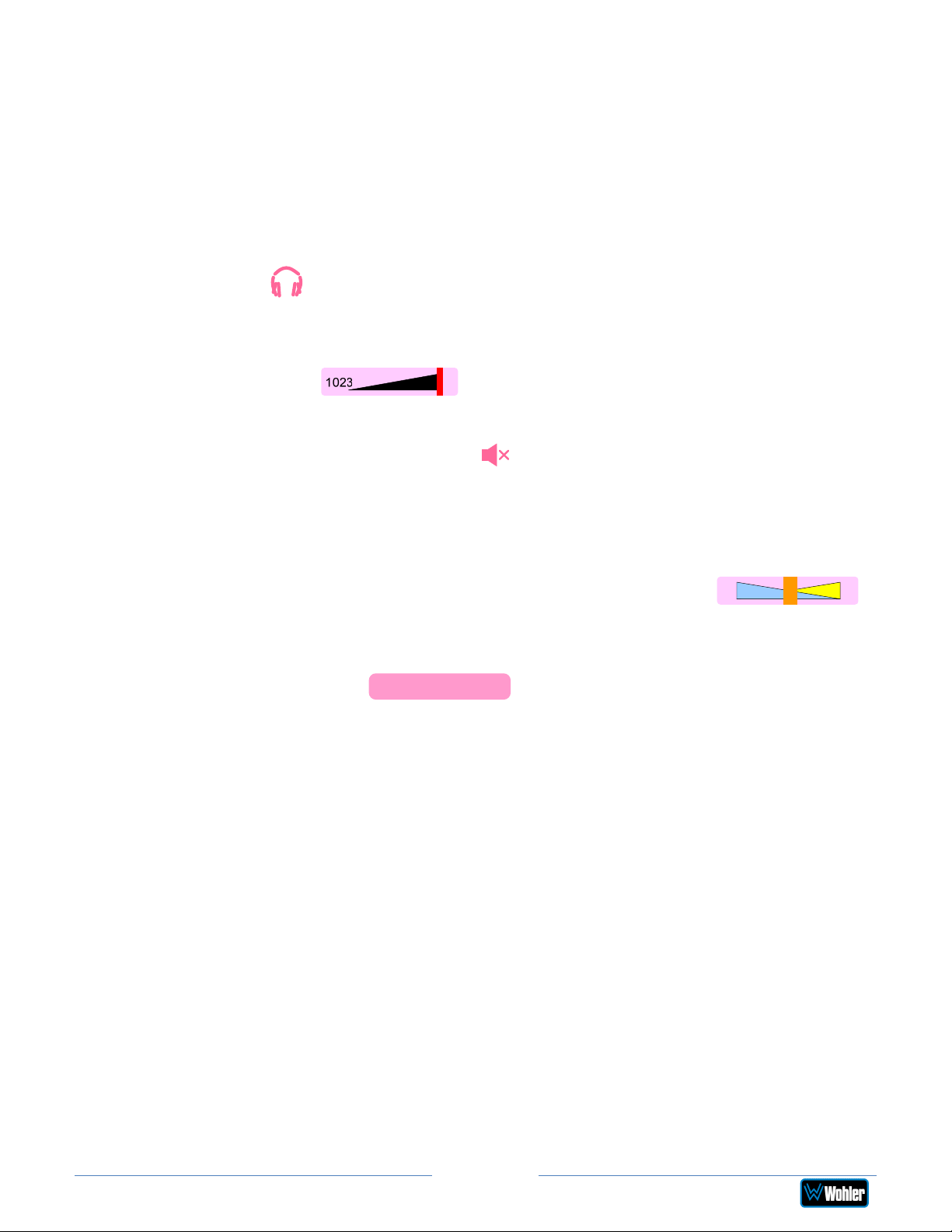
4. Headphone Jack: A 1/4" jack for an optional headphone is provided on the front
panel. Speaker audio can be optioned to either mute or not mute when
headphones are plugged in. This is set in the Speaker Options menu. If the
speaker audio is set to mute with headphone insertion, and a headphone is plugged
into the Headphone Jack, the following icon will appear near the center top of the
Meter Screen:
5. Volume: This controls the speakers, the headphone, and the analog outputs. As
the Volume control is turned, a graphic appears at the center top of the Meter
Screen, as follows:
Pressing the Volume control mutes the audio and a speaker muted icon appears
near the center top the Meter Screen: This icon also displays whenever the
Volume control is turned all the way counterclockwise.
6. Balance: This controls the relative left/right levels for the monitored stereo mix.
Pressing the knob will bring the balance back to center. It controls the speakers,
the headphone, and the analog outputs. As the Balance control is turned, a
graphic appears at the center top of the Meter Screen as follows:
7. Source: Turning this control right or left selects between the available licensed
input sources. The selected Source input is displayed in the center of the Audio
Meters Screen as follows:
SDI-1
Alternatively, the Source control can be used to select from any Preset, or from
any Favorite Preset. Refer to the Source Knob Select setting in the Unit Config
menu. Regardless of this menu setting, when the Loudness Meter Screen is
displayed, the Source knob selects which Loudness Cluster is to be measured and
monitored.
To use the Source/Preset control to change the Channel Gain and Speaker
Assignment of a particular channel, refer to the Channel Gain and Speaker
Assignment paragraph of the Channel Meters and Touch Operations section
of this chapter.
8. Channel: Turning this control moves a white selection box from channel to channel
on the metering screen. Press the control to solo the highlighted channel. The box
will turn blue and any other boxes will disappear. To remove the solo and return to
the previous monitoring configuration, press the Channel control once again.
9. USB: This USB 2.0 Type A connector allows you to use a flash drive (not supplied)
to perform software updates and copy system configurations to another
iAM2-8
or
to a PC. Refer to Appendix A of this manual to learn about performing a software
update.
Page 11
iAM2-8
Page 12
Important:
10. Status: This indicator lights green when the system is powered and ready for use.
A solid or blinking yellow color indicates that the product is starting up. A red color
indicates that a system update is taking place. Refer to Appendix A for procedures
to update software.
Rear Panel
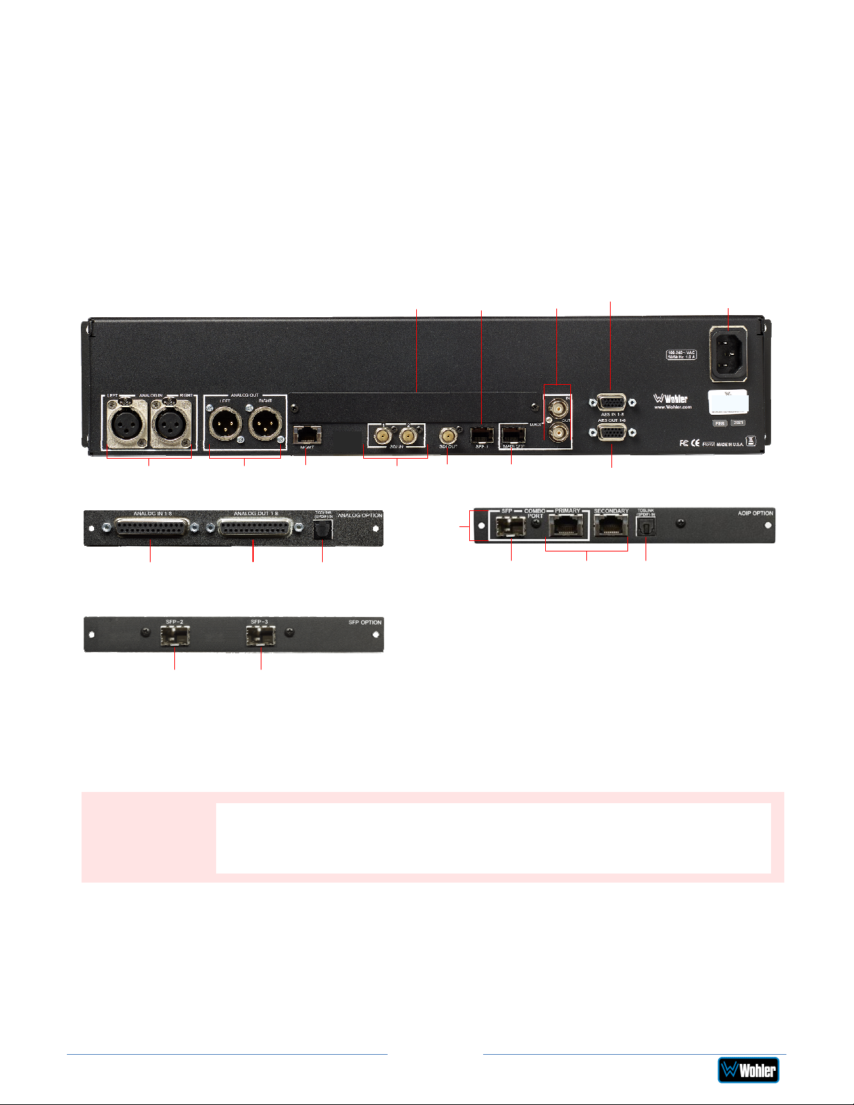
The rear panel is shown in Figure 2-2.
Figure 2-2: iAM2-8 Rear Panel & Option Cards
Power
Connection
Balanced
Analog Inputs
Balanced DB-25
Analog Inputs
SFP Module
Cage
Balanced
Analog Outputs
Balanced DB-
25 Analog
Outputs
SFP Module
Cage
Network
Port
TOSLINK
Optical
Input
Option
Card Slot
SDI
Inputs
SDI
Output
Combo
Port
SFP Module
Cage
MADI
Fiber SFP
AoIP SFP
Module Cage
MADI
AES Inputs
BNC
AES Outputs
Primary /
Secondary
1GB Ethernet
Ports
TOSLINK
Optical
Input
Power Connection: The iAM2-8 receives power from an AC inlet, which is a standard
IEC receptacle for 100 to 240 VAC ±10%, 50/60 Hz power connection. Four regional AC
power cords, supplied according to shipping region, are available.
iAM2-8
By design, the supplied AC mains power cord will only plug into a
three-prong grounded outlet for your safety. If the plug does not fit
into the outlet, contact an electrician to replace the obsolete outlet.
1. SDI Inputs: These two BNC connectors accept the two 3G/HD/SD-SDI
input signals containing the audio to be monitored. This is a standard
feature.
2. SDI Output: This BNC connector outputs the selected 3G/HD/SD-SDI or
SFP module input signal.
Page 12
Page 13
3. Network Port: This Ethernet port can connect to either a LAN or to a PC
to let you perform administrative tasks remotely. The Wohler Web GUI is
described in Chapter 4 of this manual. Third party equipment, connecting to
the iAM2-8 via a LAN plugged into this port and using an API commands, can
view and change product options, as well. This API is described in Appendix E
of this manual.
4. MADI BNC: (optional) The COAX input accepts an AES10 64-channel
signal at 48 kHz sample rate. An optional license key must be purchased to
enable this function. The COAX output is reclocked from the MADI source.
When power to the iAM2-8 is not present, the COAX input and output are
automatically connected together to allow the MADI signal to pass
through. A software license must be installed for this input to function.
Refer to the System Setup section in Chapter 4 to install software
licenses.
5. MADI Fiber SFP: (optional) This input module accepts an optical AES10
64-channel MADI input signal at 48 kHz sample rate. An optional license
key must be purchased to enable this function. A software license must be
installed for SFP ports to function. Refer to the System Setup section in
Chapter 4 to install software licenses.
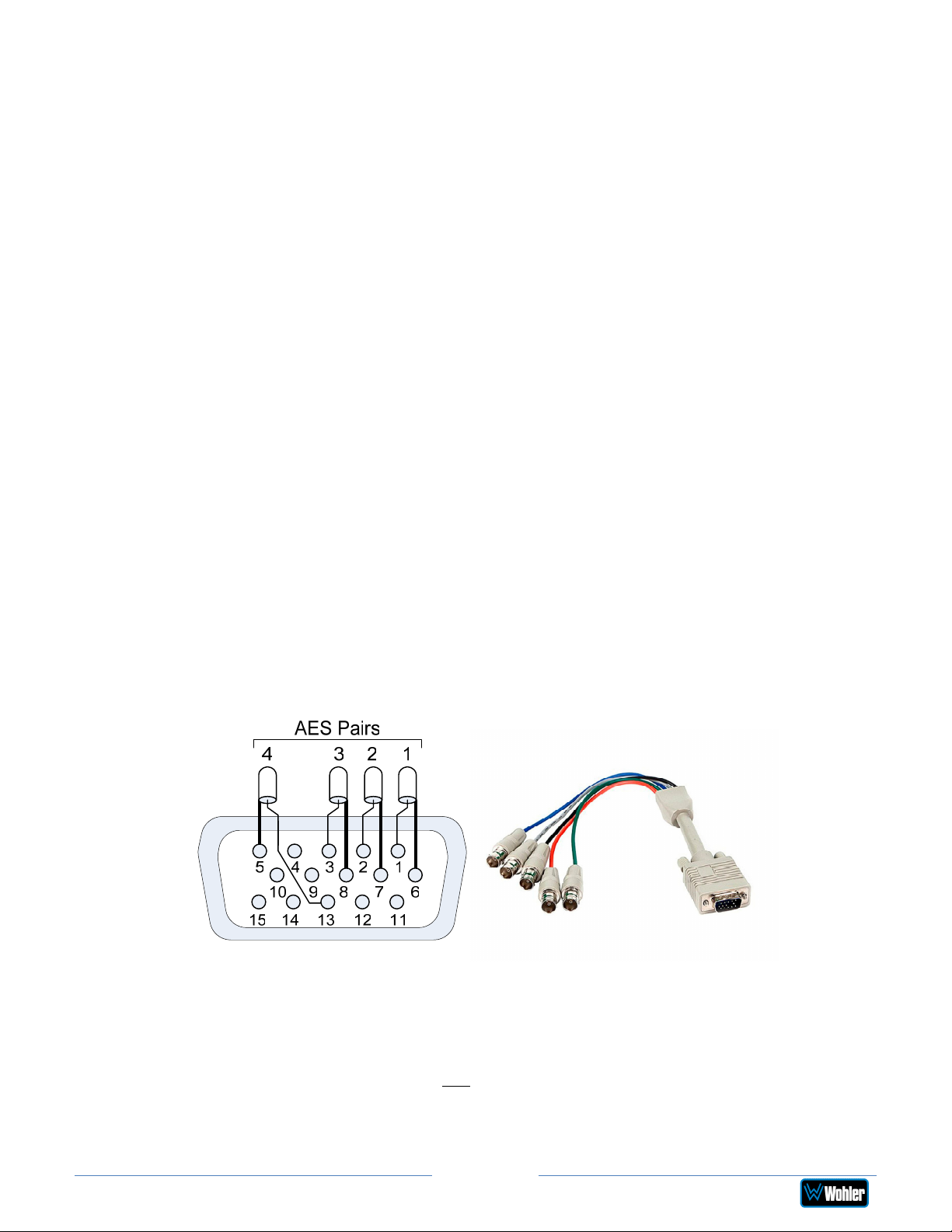
6. AES Inputs: (optional) This HD-15F connector accepts 4 AES3id digital
audio pairs (8 channels) at a 48 kHz sample rate. Refer to Figure 2-3 for
the pinout of this connector. The easiest way to interface with this
connector is to use an HD-15 to VGA adaptor cable. Channels are selected
as AES 1-8. A software license must be installed for these inputs to
function. Refer to the System Setup section in Chapter 4 to install
software licenses.
Figure 2-3: AES HD-15F Connector Pinout
7. AES Outputs: This HD-15F connector provides 4 AES3id digital audio
pairs (8 channels) at a 48 kHz sample rate from selected monitored
sources. Refer to Figure 2-3 for the pinout of this connector. The easiest
way to interface with this connector is to use an HD-15 to VGA adaptor
cable. These outputs are not controlled by the Volume and Balance
controls. Monitored channels 1 and 2 are sent from AES-1, channels 3 and
4 are sent from AES-2, channels 5 and 6 are sent from AES-3, and
Page 13
iAM2-8
Page 14
channels 7 and 8 are sent from AES-4.
8. SFP Module Cage: An SFP cage is provided to accept one optional SFP
module compatible with SDI coaxial or optical signals. The SFP modules
are hot swappable for convenience. An optional license key must be
purchased to enable each module. A software license must be installed for
the SFP port to function. Refer to the System Setup section in Chapter 4
to install software licenses. The following SFP modules are offered:
a. 3G/HD/SD-SDI Single Video Receiver with Active Loopback:
This uses HD-BNC connectors.
b. 3G/HD/SD-SDI Video SFP with Optical Input: This uses LC
fiber connectors. It is a Single-Mode Receiver, Medium Haul, NonMSA, and no output.
c. SMTPE 2022-6 Receiver: This uses Multi-Mode 850 NM, LC fiber
connectors. It allows the iAM2-8 to monitor SDI audio transmitted
in real time over Ethernet. You must use the MN-Set configuration
software to set up this option. It is available from Wohler
Technologies Technical Service.
d. SMTPE 2110 Receiver: This uses Multi-Mode 850 NM, LC fiber
connectors. It allows the iAM2-8 to monitor SDI audio transmitted
in real time over Ethernet. You must use the MN-Set configuration
software to set up this option. It is available from Wohler
Technologies Technical Service.
e. SMTPE 2110 or 2022-6 Receiver: This uses Multi-Mode 850 NM,
LC fiber connectors. It allows the iAM2-8 to monitor SDI audio
transmitted in real time over Ethernet. You must use the MN-Set
configuration software to set up this option. It is available from
Wohler Technologies Technical Service.
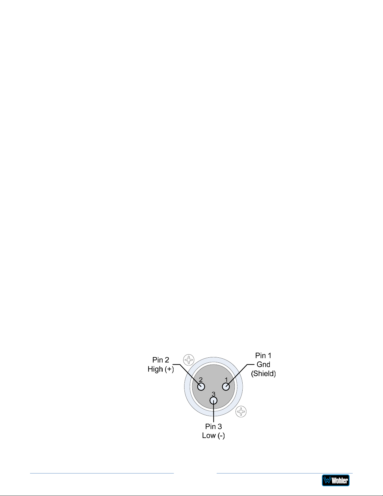
9. Analog Inputs: These female XLR connectors provide two balanced
analog inputs:
Left
and
Right
. The Analog Inputs are standard on the
iAM2-8. Refer to Figure 2-4 for the pinout of this connector.
Figure 2-4: Analog XLR-F Output Connections
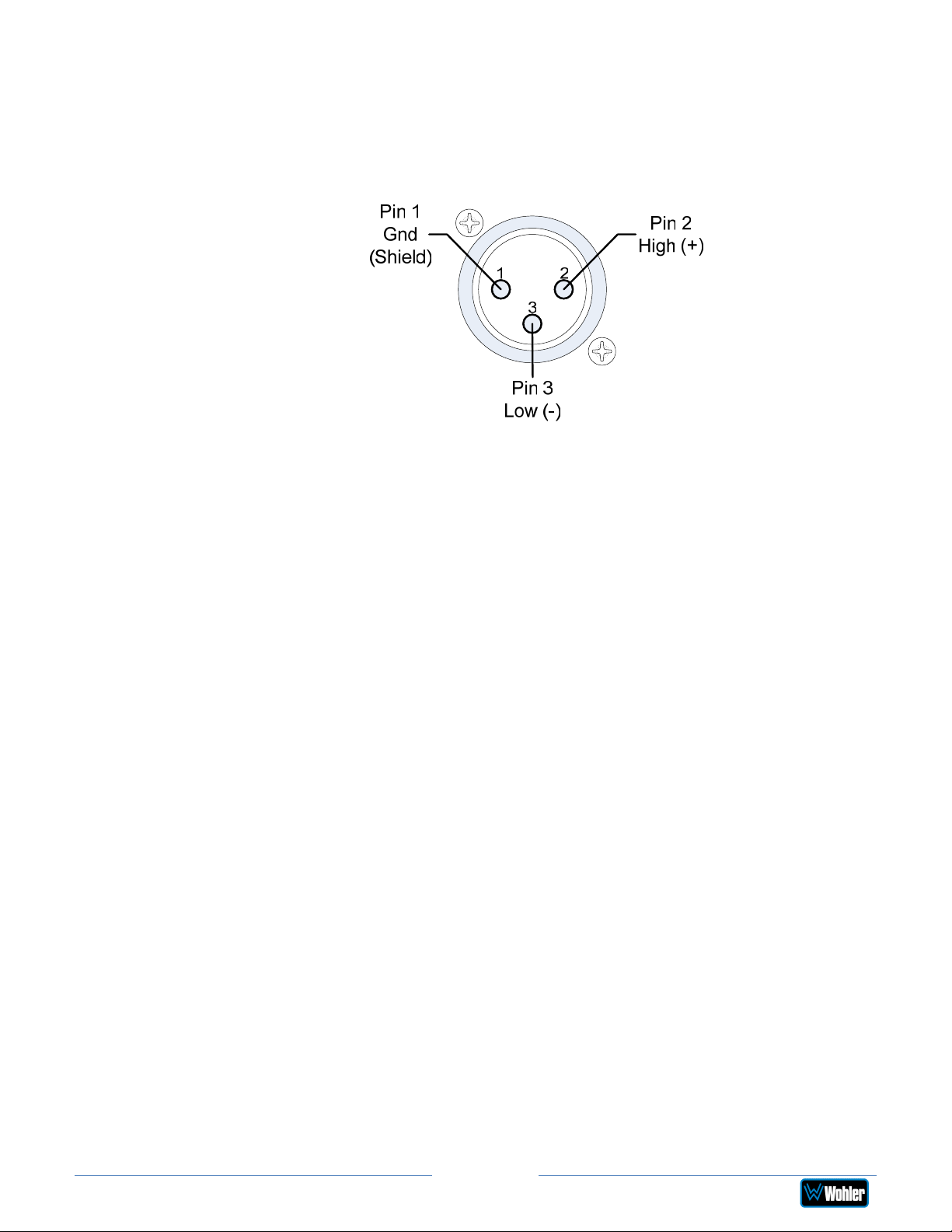
10. Analog Outputs: These male XLR connectors provide two balanced
Page 14
iAM2-8
Page 15
analog outputs:
Left
and
Right
. The source of these signals is the mix of
audio as monitored by the internal speakers and is adjusted by the
Volume and Balance controls. The Analog Outputs are standard on the
iAM2-8. Refer to Figure 2-5 for the pinout of this connector.
Figure 2-5: Analog XLR-M Output Connections
11. Option Card Slot: This metal plate can be removed to reveal a location
in which future optional modules can be installed.
12. TOSLINK Optical Input (optional): This connector is located on the
panel of the optional OPT-iVAM ANALOG Option card, as well as on the
panel of the AoIP Option card. It provides an optical stereo pair input.
13. Balanced Analog DB-25 Outputs (optional): This DB-25 female
connector outputs 8 channels of +10dBu broadcast level balanced audio.
This connector is located on the panel of the optional OPT-iVAM ANALOG
Option card. The source of these signals is the monitored audio channels
as shown on meters 1 - 8. Tascam cables may be used, and can be
purchased by contacting Wohler Sales. Refer to Figure 2-6 for the pinout
of this connector.
Note: PCM channels marked as data channels (such as those containing
encoded Dolby streams) are automatically muted from being sent out to the
external amplifier and speakers.
Note: When these outputs are used to connect to an external amplifier and
speakers, the external amplifier should be muted whenever the iAM2-8 is
being powered up or powered down.
14. Balanced Analog DB-25 Inputs (optional): This DB-25 female
connector inputs 8 channels of up to +10dBu broadcast level balanced
audio. This connector is located on the panel of the optional OPT-iVAM
ANALOG Option card. These signals are monitored on meters 1 - 8 by
default. Tascam cables may be used, and can be purchased by contacting
Wohler Sales. Refer to Figure 2-6 for the pinout of this connector.
Page 15
iAM2-8
Page 16
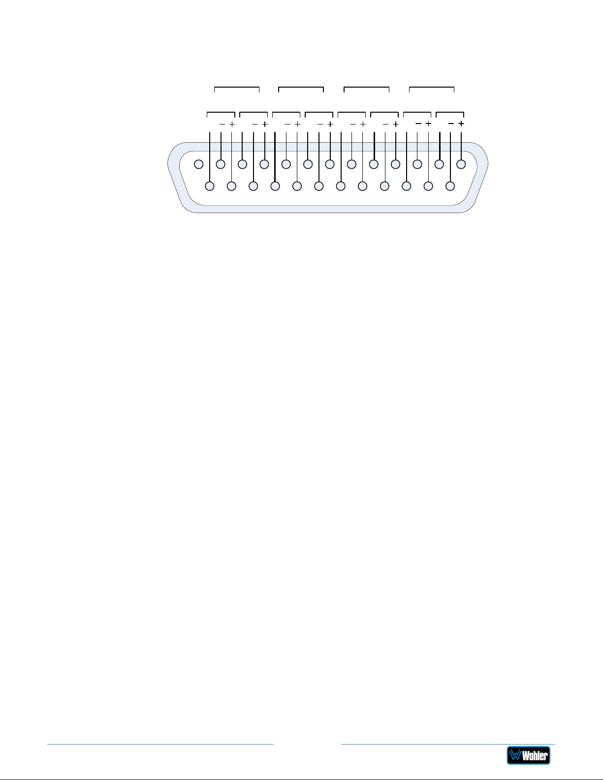
Figure 2-6: Analog DB-25F Input and Output Connections
Pair 1 Pair 2 Pair 3 Pair 4
L R L R L R L R
GG
12345678910111213
141516171819202122232425
N/C
GGGG
GG
15. AoIP SFP Module Cage (optional): This provides a location in which to
insert the AoIP Module supplied with the OPT-DANTE (iVAM) and OPT
RAVENNA 64 options.
16. Primary / Secondary 1GB ENET (optional): Primary and Secondary
Gigabit Ethernet interfaces are provided with the AoIP option module.
17. Combo Port (optional): An optional 1GB Fiber Ethernet SFP module and
the Primary RJ-45 Ethernet port on the option card operate as a combo
port, that is, they provide two different physical layers, optical fiber or
electrical, but share the same Ethernet characteristics. However, the two
different ports cannot be used simultaneously. You must choose to
connect either one or the other.
Page 16
iAM2-8
Page 17
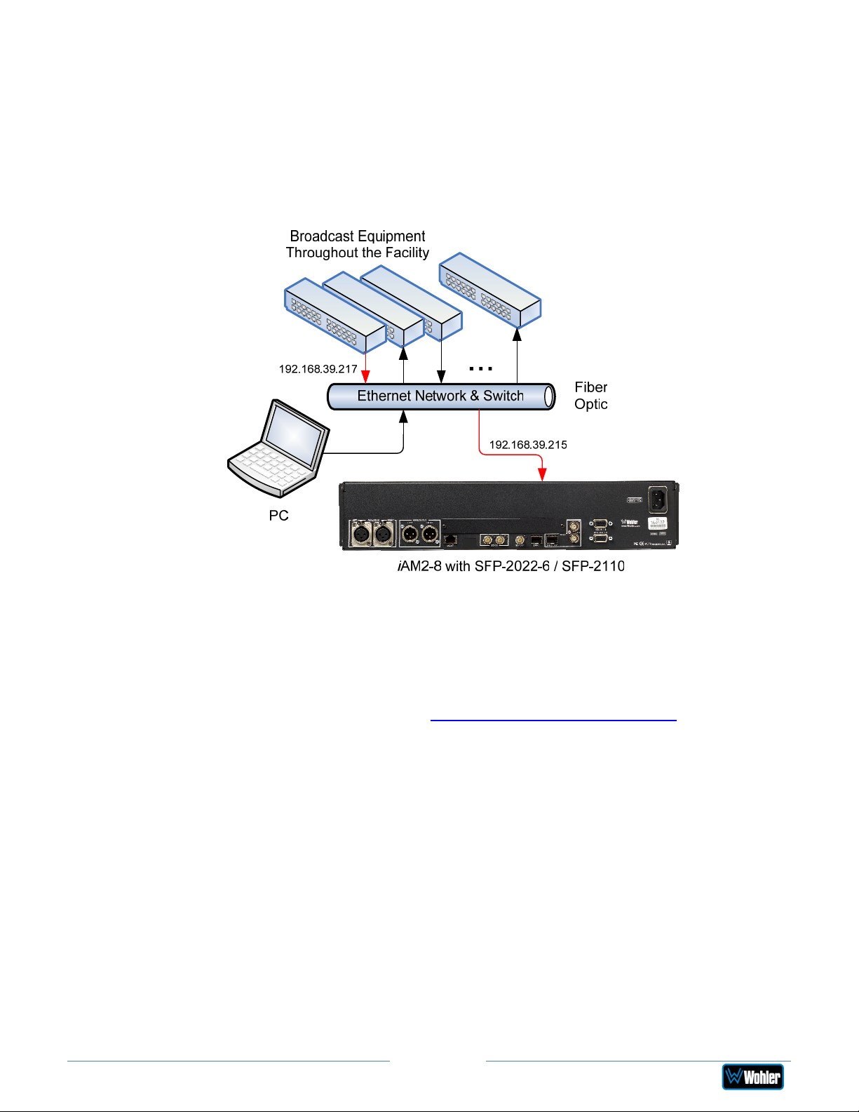
SFP-2022-6 / SFP-2110 Address Setup
While the optional SFP-2022-6 and SFP-2110 modules monitor program audio
created from distinctly different technologies, both are connected to the network in
the same way and have the same requirements for addressing. Figure 2-7
illustrates the network connections they need.
Figure 2-7: SFP-2022-6 and SFP2110 Network Diagram
The optional SFP-2022-6 or SFP-2110 module furnished by Wohler Technologies is
manufactured by Embrionix and comes from the factory with a default IP address.
To integrate it into your digital network, you need to set its address to the source to
be monitored. You must use the MN-Set configuration software to set up this
option. It is available from Wohler Technologies Technical Service. The procedure to
accomplish this is described in the SFP-2022-6 / SFP-2110 Setup Guide (part
number 821822), which is available at https://wohler.com/downloads/ .
Page 17
iAM2-8
Page 18
Channel Meters and Touch Operations
The audio mixer terminology of “solo” is used in this manual when referring to
muting all but a specific audio channel or pair.
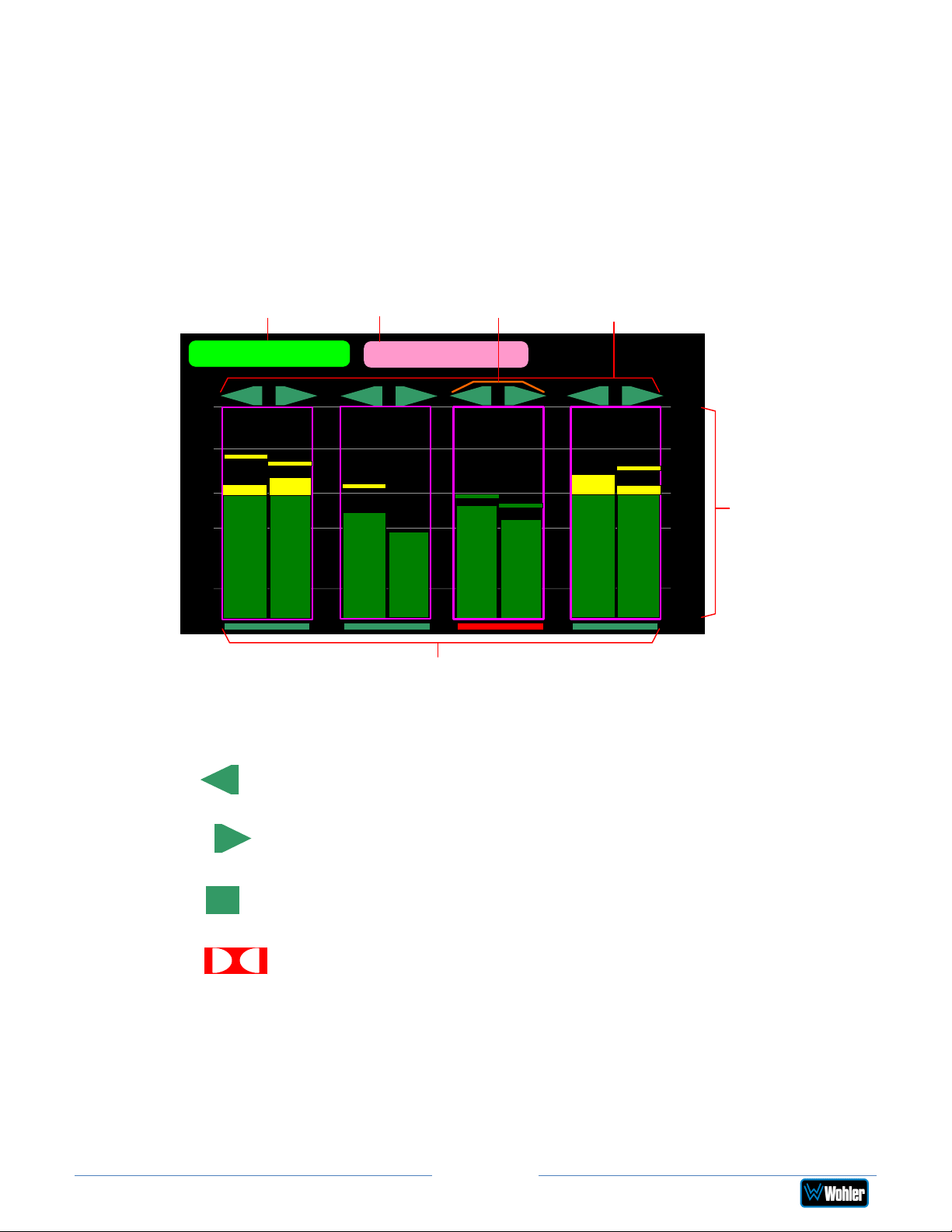
Audio meters are displayed on touchscreen LCD display(s) in up to 8 channel pairs,
as shown in Figure 2-8.
Figure 2-8: Audio Level Meter Screen
Loudness
Reading
LKFS-M : -24.6
1
-00
-20
-30
-40
2
S
t
e
r
e
o
Source /
Preset
3
Loudness Cluster
Marker
SDI-1
4
5
S
t
e
r
e
o
6
Channel
Identifiers
S
t
e
r
e
o
7
8
-00
S
t
-20
e
r
e
-30
o
-40
Channel
Pair Touch
Selection
Area
-60
Phase Indicators
1. Channel Identifiers: Above the level meters are the Channel Identifiers.
They indicate the consecutive channel numbers in the selected source.
-60
1
An arrow pointing to the left indicates that this is a left channel and
will be monitored in the left speaker.
2
An arrow pointing to the right indicates that this is a left channel and
will be monitored in the right speaker.
A square indicates that this is a center channel and will be monitored
3
in both speakers.
This symbol indicates that this channel pair is a Dolby bitstream.
87
Refer to the Dolby Zoom section of this chapter.
2. Source/Preset: This displays the name of the Source or Preset currently
being displayed.
3. Loudness Cluster Marker: This orange bracket marks which cluster is
currently being measured for Loudness.
4. Loudness Reading: This control displays the Loudness of the selected
Page 18
iAM2-8
Page 19

Cluster. It can also be touched to change which Cluster is being
measured. To do this, touch the green Loudness Reading control. It will
temporarily turn orange. You may then touch the meters in any other
cluster. The Loudness Cluster Marker will then move to that cluster and
its measurement will begin and be displayed. You may then touch the
control again to return it to its green color, restoring normal touch
functioning, or wait 15 seconds for it to time out.
5. Channel Pair Touch Selection Area: Touching the meters of any
channel pair will let you mute, un-mute, or solo the associated
channel(s). Colored boxes surrounding the channel pair or channel
indicate what operation is being performed. The following describes each
function:
a. Mute / Un-Mute Selection: A violet box surrounds any channel
pair that is muted. Typically, when the iAM2-8 is first powered, all
of the channel pairs are muted. Touching a muted channel pair unmutes it and removes the violet box. Muting and un-muting by
touching is an alternate action function.
b. Solo Selector: Touch for two seconds any channel pair you would
like to solo. A blue box will then surround the pair and that will be
the only pair you hear. Any violet boxes will disappear. Touching
another channel pair will then move the blue box to it, and it will be
soloed. Touch again to return the combination of monitored channel
pairs to the way they were before you soloed the pair.
c. Channel Solo: Rotating the Channel control will move a white
selection box from channel to channel. Press the Channel control
to solo the selected channel. That channel alone will then be
surrounded by a blue box and it will be the only channel being
monitored. Press the Channel control again or touch anywhere on
the meters to undo the solo and return the combination of
monitored channel pairs to as it was before you soloed the channel.
6. Channel Gain and Speaker Assignment: The channel gain and speaker
assignment of a particular channel can be changed dynamically from the
Front Panel controls. When a channel is soloed (as in the Solo Selector
paragraph above) the Source/Preset knob can be used to perform the
following operations:
a. Adjust Channel Gain: The user can rotate the Source/Preset
knob to adjust the channel gain for the soloed channel. This affects
the input channel gain. Valid range is from -60 to 12 dB. The
selected gain will display at the top of the screen:
Changing channel gain affects all the outputs that have “Volume
Control” enabled.
b. Channel Assignment Change: Press the Source/Preset knob
once to toggle to Channel Assignment Change mode. In this
mode, rotating the Source/Preset knob changes the speaker that
the channel is assigned to. The valid assignments are: Left, Right,
iAM2-8
Page 19
Page 20

Center, LFE, Left Surround, Right Surround, Back Surround Left,
Back Surround Right, Mono Surround. The selected assignment will
appear at the top of the screen: This assignment
only affects the internal speakers and no other outputs.
Note: In Solo mode, the Source/Preset knob cannot be used to
change the source. The changes made to the channel gains and/or
speaker assignments are temporary and revert to the original values
when a Source Select or Preset Recall operation is performed.
7. Phase Indicators: At the bottom of each channel pair is a Phase
Indicator. The indicators light a dull green if the channels in the pair are
in phase or bright red if they are out of phase. You may set which Phase
Indicators appear using the Phase Config Menu or with the System
Preferences: Phase Indicator Configuration tab in the Wohler Web
GUI.
Page 20
iAM2-8
Page 21
Dolby Zoom Screen
Dolby Zoom is a very powerful analysis tool. Much as a camera lens can "zoom"
into a single subject of interest out of many, the Dolby Zoom feature lets you
quickly "zoom" into a single Dolby bitstream, out of multiple encoded Dolby
streams and other channels. You can immediately listen to and meter the contained
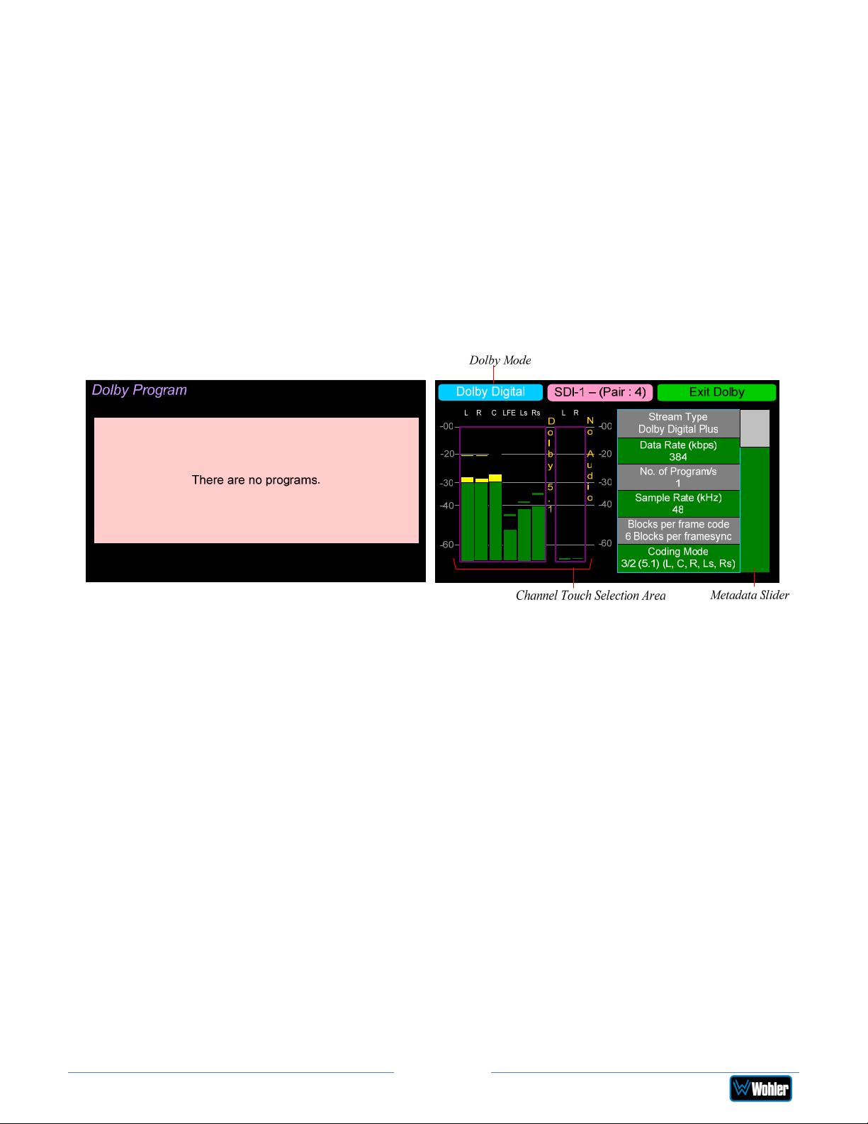
audio channels, as well as view the Dolby metadata. Bitstreams are shown
distinctively along with the normal metering channels, as shown in Figure 2-8. The
Dolby Zoom Screen is shown in Figure 2-9.
Dolby decoding is an optional feature requiring the OPT-DOLBY module. It
allows decoding and monitoring of Dolby® D, DD+, & E streams.
System Setup section in Chapter 4 to install software licenses.
Figure 2-9: Dolby Zoom Screen
Refer to the
When the Dolby Zoom screen appears, up to 8 decoded Dolby channels will appear
on the meters. You may use a Dolby Preset to display the downmix on any pair of
meters. As shown in the figure above, SDI-1 – (Pair : 4) indicates that the meter
bar graphs and metadata are derived from the Dolby bitstream on the fourth pair of
input SDI-1. However, you may solo or mute the individual channels for
troubleshooting or other purposes. Use the left screen to select other Dolby E
channels to be monitored. Touch and slide the control on the Dolby Metadata
screen to scroll through multiple lines of metadata.
A wide range of Metadata is available, which can help you diagnose possible
problems. It will vary according to the type of Dolby signal. For example, for
checking Guard Band, the iAM2-8 will display the Line Position of each Dolby E
bitstream in the Dolby signal.
Touching the Exit Dolby button returns you to the monitoring screen from which
you came.
Page 21
iAM2-8
Page 22
Menu / Option Touchscreen
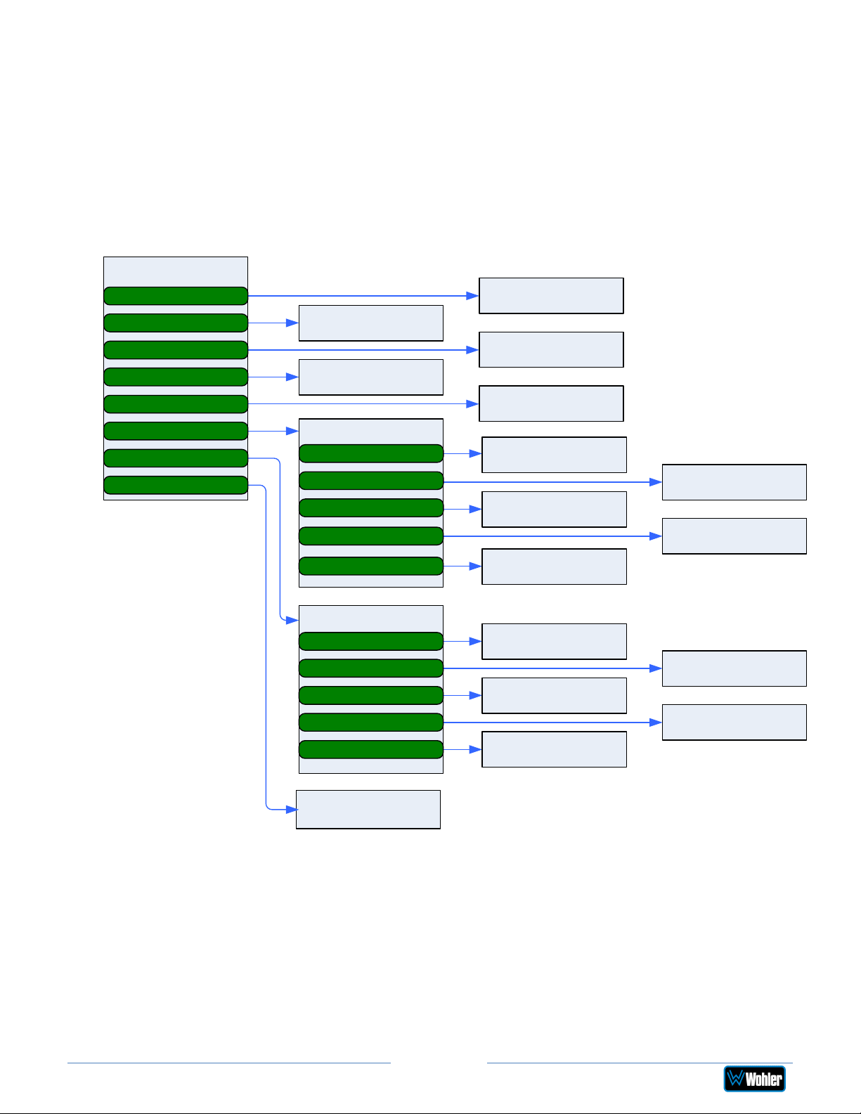
You may set most options or view a variety of system information using the selfcontained menus. Figure 2-10 is a diagram of the menu arrangement, a tree
showing how to reach any menu from the Main Menu. Hold the Source knob
pressed for two seconds to access the Main Menu. Figure 2-11 shows the Main
Menu.
Figure 2-10: Menu Tree
Main Menu
Source Select
Preset Favorites
All Presets
Loudness Meter
Loudness Settings
Unit Settings
System Options
System Details
Preset Favorites
Screen
Loudness Meter
Screen
Unit Settings
Speaker Options
Meter Scales
Unit Configuration
Phase Configuration
Analog Config
Source Selection
Screen
All Presets Screen
Loudness Settings
Screen
Speaker Options
Screen
Unit Configuration
Screen
Analog Config
Screen
Meter Scales
Screen
Phase Configuration
Screen
System Options
Network Settings
System Reboot
System Update
Factory Reset
Passcode Settings
System Details
Screen
Network Settings
Screen
System Update
Screen
Passcode Settings
Screen
System Reboot
Screen
Factory Reset
Screen
Page 22
iAM2-8
Page 23
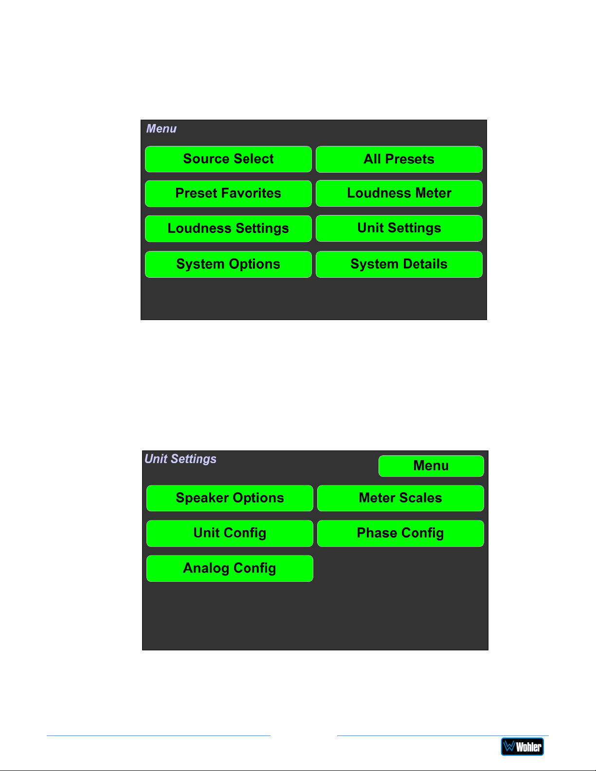
Main Menu
Hold the Source knob pressed for two seconds to access the Main Menu. The
Main Menu is shown in Figure 2-11.
Figure 2-11: Main Menu
Unit Settings
Touching the Unit Settings selection on the Main Menu screen proceeds to the
Unit Settings Menu, which contains additional menu selections. The Unit
Settings Menu is shown in Figure 2-12. This is an intermediary menu which leads
to other menus and screens.
Figure 2-12: Unit Settings Menu
Page 23
iAM2-8
Page 24
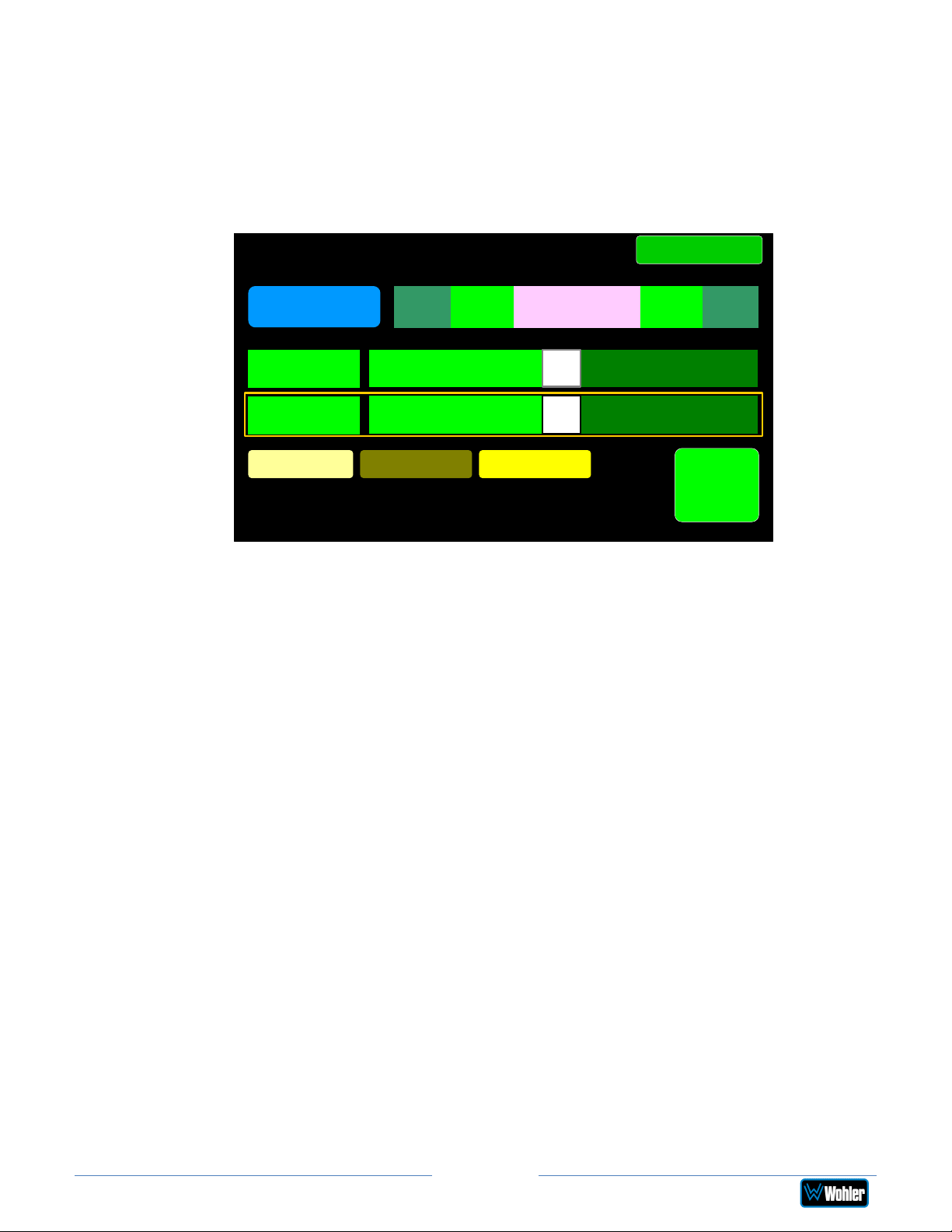
Speaker Options
Touching the Speaker Options selection on the Unit Settings Menu screen
proceeds to the Speaker Options screen. The controls on this screen affect
various characteristics of the monitored audio as heard on the iAM2-8. This screen
is shown in Figure 2-13.
Figure 2-13: Speaker Options Screen
Speaker Options
Volume
Reference
Treble
0 dB
Bass
0 dB
Low Cut On Off
<< >>><
0
Back
12-12
Set to
Flat
The controls function as follows:
1. Volume Reference: The Volume Reference setting controls the
attenuation level of the internal speakers. The value ranges from 0 to -255
dB. 0 results in full volume and -255 causes the speakers to be muted.
2. Treble: This tone control adjusts the high frequency speaker audio response
from -12 dB to +12 dB. Lowering Treble compensates for high frequency
pre-emphasis or removes sibilance effects. Increasing Treble will add
“sizzle” to the sound and bring high-pitched sounds out of the mix. The
control can be touched and moved left or right to adjust in 2 dB increments.
After touching the Treble control, the Channel knob can also be turned to
make the adjustment.
3. Low Cut: Low Cut is provided for cases where unusually deep content
produces audible distortion and interferes with monitoring.
4. Bass: This tone control adjusts the low frequency speaker audio response
from -12 dB to +12 dB. Lowering Bass will unmask midrange band sounds,
while increasing Bass will make the sound “fatter”. The control can be
touched and moved left or right to adjust in 2 dB increments. After touching
the Bass control, the Channel knob can also be turned to make the
adjustment.
5. Set to Flat: This button sets both the Treble and Bass controls to 0 dB,
removing any emphasis or de-emphasis they can provide. Selecting Flat
provides the flattest measured response from the internal speakers.
Touch Back to exit this screen.
Page 24
iAM2-8
Page 25
Meter Scales
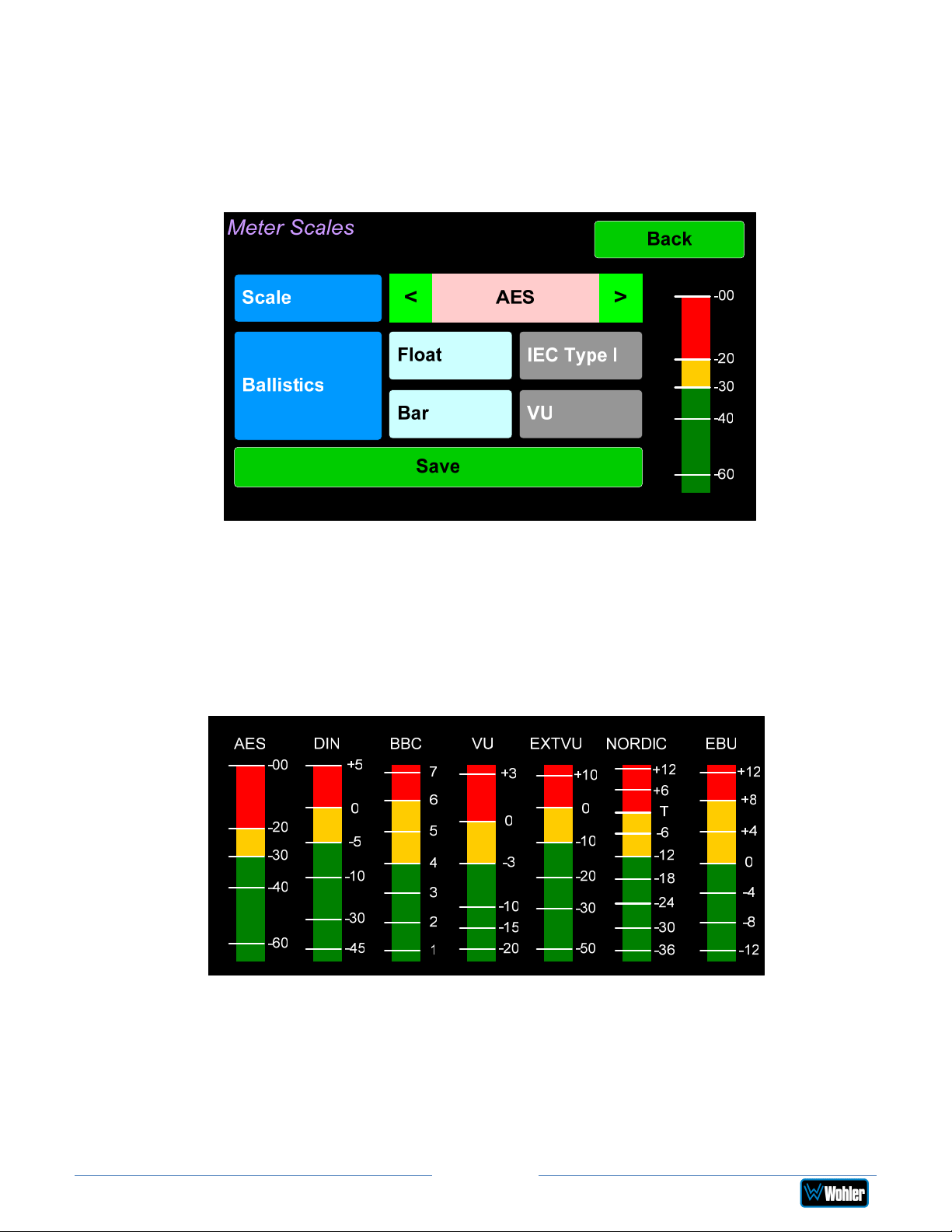
Touching the Meter Scales button on the Unit Settings Menu displays the Meter
Scales screen as shown in Figure 2-14. The controls on this screen select the scale
standards as well as the ballistics that will be applied to the audio meters.
Figure 2-14: Meter Scales Screen
The controls function as follows:
1. Scale: This meter scales standard to be used when displaying audio levels. A
choice of seven scales is available. Touch the left or right arrows to select
the scale. A representation of the chosen scale will be shown at the right.
The possible scales that can be selected are shown in Figure 2-15.
Figure 2-15: Meter Scale Selection
Page 25
iAM2-8
Page 26
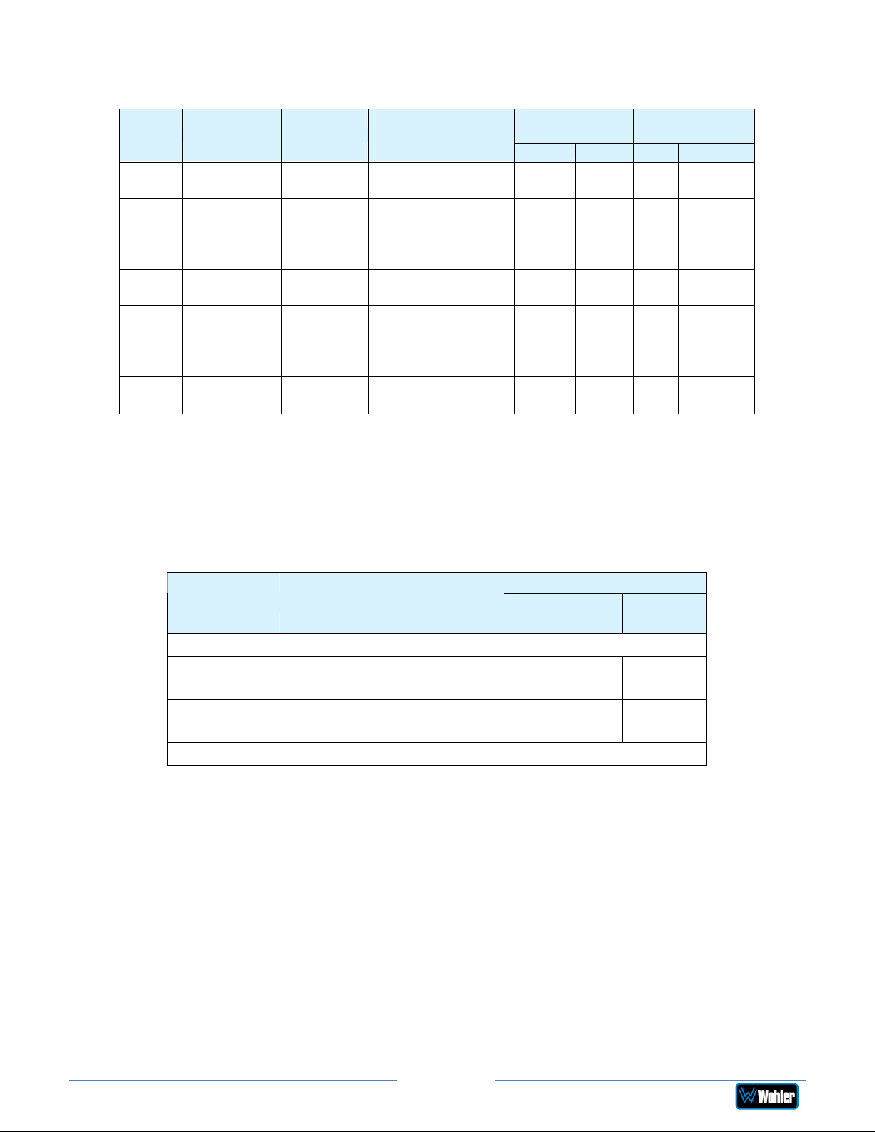
Table 2–4: Meter Limits and References
Scale Bottom Limit Top Limit
AES -72 dBFS 0.0 dBFS 0 dBFS = 0 dBFS -30 dBFS -20 dBFS
DIN -53 dBr +5.5 dBr -15 dBFS = 0 dBr -5 dBr 0 dBr — IEC Type I
BBC
VU -45 dBr +3.5 dBr -20 dBFS = 0 dBr -3 dBr 0 dBr — VU
EXTVU -56 dBr +16.0 dBr -20 dBFS = 0 dBr -10 dBr 0 dBr — VU
NORDIC -44 dBr +12.5 dBr -18 dBFS = 0 dBr -10 dBr 0 dBr — IEC Type I
EBU
-13.25 dBr +13.0 dBr -18 dBFS = 0 dBr 0 dBr 8 dBr — IEC Type I
-13.25 dBr +13.0 dBr -18 dBFS = 0 dBr 0 dBr 8 dBr — IEC Type I
Default
Reference
Default Color
Bounds
Lower Upper Float Bar
Default Ballistics
IEC
Type I
VU
2. Ballistics: The Bar and Float ballistics associated with the selected meter
scale are displayed. Refer to Table 2-5. Ballistic timings are valid only at 48
kHz.
Table 2–5: Meter Timings
Fall
Ballistics Rise
Level
Change
Time
VU Not Specified
IEC Type I
5 ms to reach -2 dB of
-20 dB 1.7 sec.
settled reading
IEC Type II
10 ms to reach -2 dB of
-24 dB 2.8 sec.
settled reading
None Bar or Floating Segment Not Displayed
When you have made your choices, touch Save to retain them. Touch Back to exit
this screen.
Page 26
iAM2-8
Page 27
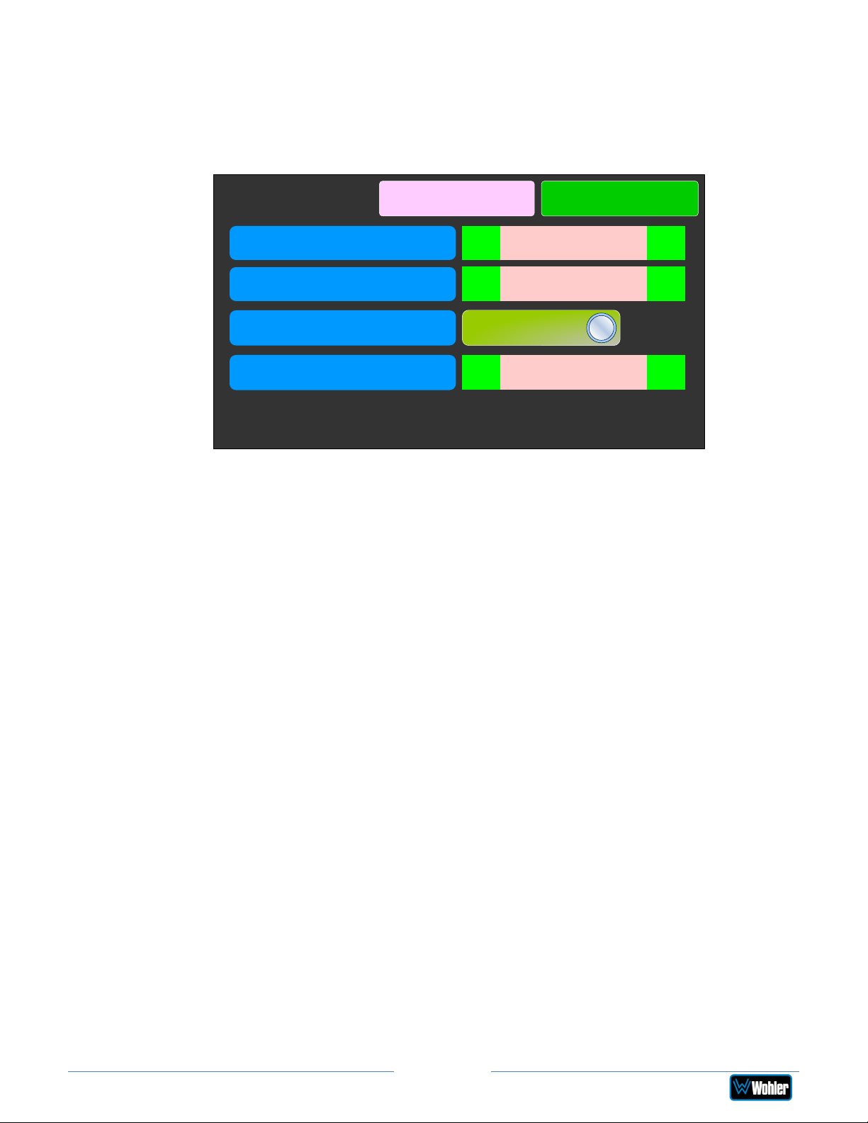
Unit Configuration
Touching the Unit Config selection on the Unit Settings Menu proceeds to the
Unit Configuration Menu. This menu is shown in Figure 2-16.
Figure 2-16: Unit Configuration Menu
Unit Configuration
Right LCD Brightness
Left LCD Brightness
AES Termination
Source Knob Selection
The controls function as follows:
1. Right LCD Brightness: This setting adjusts the brightness of the right
display screen, which is used for meter displays and menus. Touch the left
pointing arrow to dim the brightness or touch the right pointing arrow to
increase the brightness.
Cancel & Exit Save & Exit
< >
< >
50
50
On
Source Select
< >
2. Left LCD Brightness: This setting adjusts the brightness of the left display
screen. Touch the left pointing arrow to dim the brightness or touch the right
pointing arrow to increase the brightness.
3. AES termination: AES signals should have one and only one termination.
This termination should physically be at the last destination of an AES coax
cable. If the iAM2-8 is the last connection in a series of AES connections,
then its terminations should be turned on. A symptom of too many
terminations (or no termination) is that no signal appears to be present on
the AES input. Touch the On - Off switch to change the termination setting.
4. Source Knob Selection: This setting determines the function of the Source
knob on the front panel. It may be set as follows, depending upon your
needs:
a. Source Select: The Source knob will select the input source to be
monitored.
b. Cluster Select: The Source knob will select the Loudness Cluster to
be measured.
c. All Presets: The Source knob will select between any Presets present
in the unit.
d. No Operation: The Source knob will perform none of the above listed
selection operations. If the Source knob is set to No Operation and
iAM2-8
Page 27
Page 28
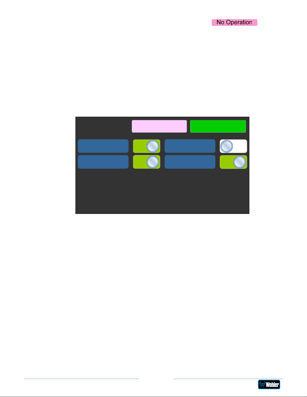
is turned, the Audio Meters screen will display for 3
seconds at the top center, as a reminder.
Note: Regardless of the Source Knob Selection, the Source knob is
used to select clusters when in the Loudness Meter Screen.
Touch Save & Exit or Cancel & Exit to exit this menu.
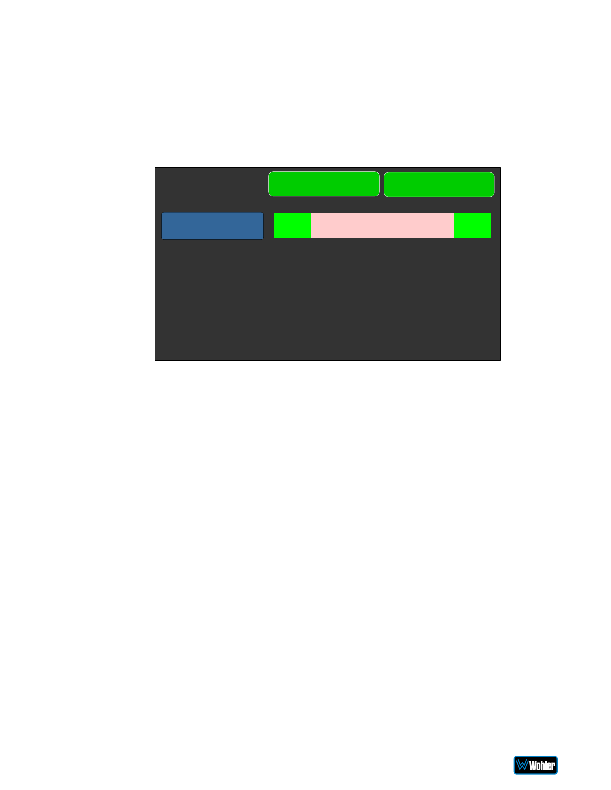
Phase Configuration
Touching the Phase Config selection on the Unit Settings Menu proceeds to the
Phase Config Menu. This menu is shown in Figure 2-17.
Figure 2-17: Phase Configuration Menu
Phase Config
Cancel & Exit
Pair - 1
Pair - 3
The controls function as follows:
1. Pair 1 - 8: These switches allow you to select which channel pairs will
receive a phase meter on the Metering Screen. Generally, it is useful to
monitor the relative phase of stereo pairs. However, sometimes each
channel of a pair is unrelated to each other. This can be because the
channels are used to convey two independent monophonic signals or that
one channel may be a Center channel and the other may be a Low Frequency
Effects channel. In these instances, the Phase Indicator would almost always
indicate an out of phase condition. Because this would be a needless
distraction to the operator, switches are provided on this screen to
individually turn phase monitoring for each channel pair on or off.
On
On
Pair - 2
Pair - 4
Save & Exit
Off
On
2. Cancel & Exit: If you decide that you do not want to keep the settings you
have made on this screen, touch the Cancel & Exit button to discard the
changes and return to the Unit Settings menu.
3. Save & Exit: When you have finished making the changes you want on this
screen, touch the Save & Exit button to save the changes and return to the
Unit Settings menu.
Page 28
iAM2-8
Page 29
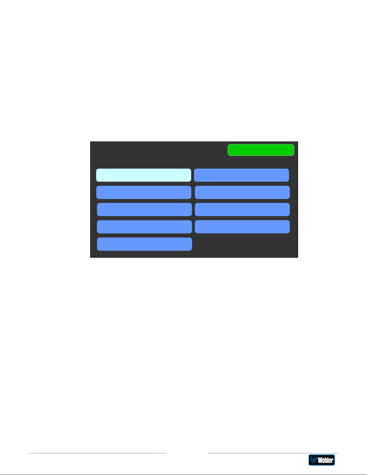
Analog Configuration
Touching the Analog Config button in the System Options Menu displays the
Analog Config screen. Contained in this menu is an Analog Reference as
illustrated in Figure 2-18. The parameters set on this screen pertain to the Analog
Input and Analog Output DB25 and XLR connectors on the rear panel of the
iVAM1-3.
Figure 2-18: Analog Configuration Menu
Analog Config
Save
Cancel
Analog Reference
There is only one setting on the Analog Reference menu:
1. Analog Reference: This setting adjusts the relationship between the
monitored digital signal level and the analog signal level that is output from
both of the DB25 and both of the XLR connectors on the back panel. The
default setting is -20 Dbfs = +8 dBu as shown in Figure 2-18. The range of
possible settings is as follows:
a. -20 dBFS = +8 dBu
b. -20 dBFS = 0 dBu
< >
-20 dBFS = +8 dBu
c. -22 dBFS = +4 dBu
d. 0 dBFS = +15 dBu
e. -16 dBFS = +4 dBu
f. -18 dBFS = +4 dBu
g. -18 dBFS = 0 dBu
h. -20 dBFS = +4 dBu
Touching Save will save any changes made, or touching Cancel will return you to
the System Options menu without saving.
Page 29
iAM2-8
Page 30
Source Select
If you have set the Source Knob Selection setting in the Unit Config menu to
Source Select, you may change the monitored source by simply rotating the
Source knob.
Alternatively, touching the Source Select selection on the Main Menu proceeds to
the Source Select menu, which shows all of the possible sources. The selected
source is shown in a light color. You may simply touch another source in this menu
to switch to it. This screen also shows sources which are unlicensed and therefore
nonfunctional. These sources are shown in a gray color. To license these sources so
that they may be used, contact Wohler Technologies. Figure 2-19 shows the Source
Select Menu.
Figure 2-19: Source Select Menu
Source Select
SDI-1
SFP
MADI-BNC
AoIP
MADI OPTICAL
Analog
Menu
SDI-2
AES
TOSLINK
Touch Menu to exit this menu.
If you touch MADI BNC, MADI Optical, or SFP, an additional selection screen will be
shown, asking you select which 8 MADI channels to monitor or which SFP
functionality to monitor. An example of these screens is shown in Figure 2-20.
Note: AoIP, TosLink and/or Analog (DB25) sources are only available if the
appropriate hardware option cards are installed on the unit. Refer to Table 3-3. If
not installed, then the system will show message Feature is not supported or
requires valid hardware, as illustrated in the last screen shown in Figure 2-20.
Page 30
iAM2-8
Page 31
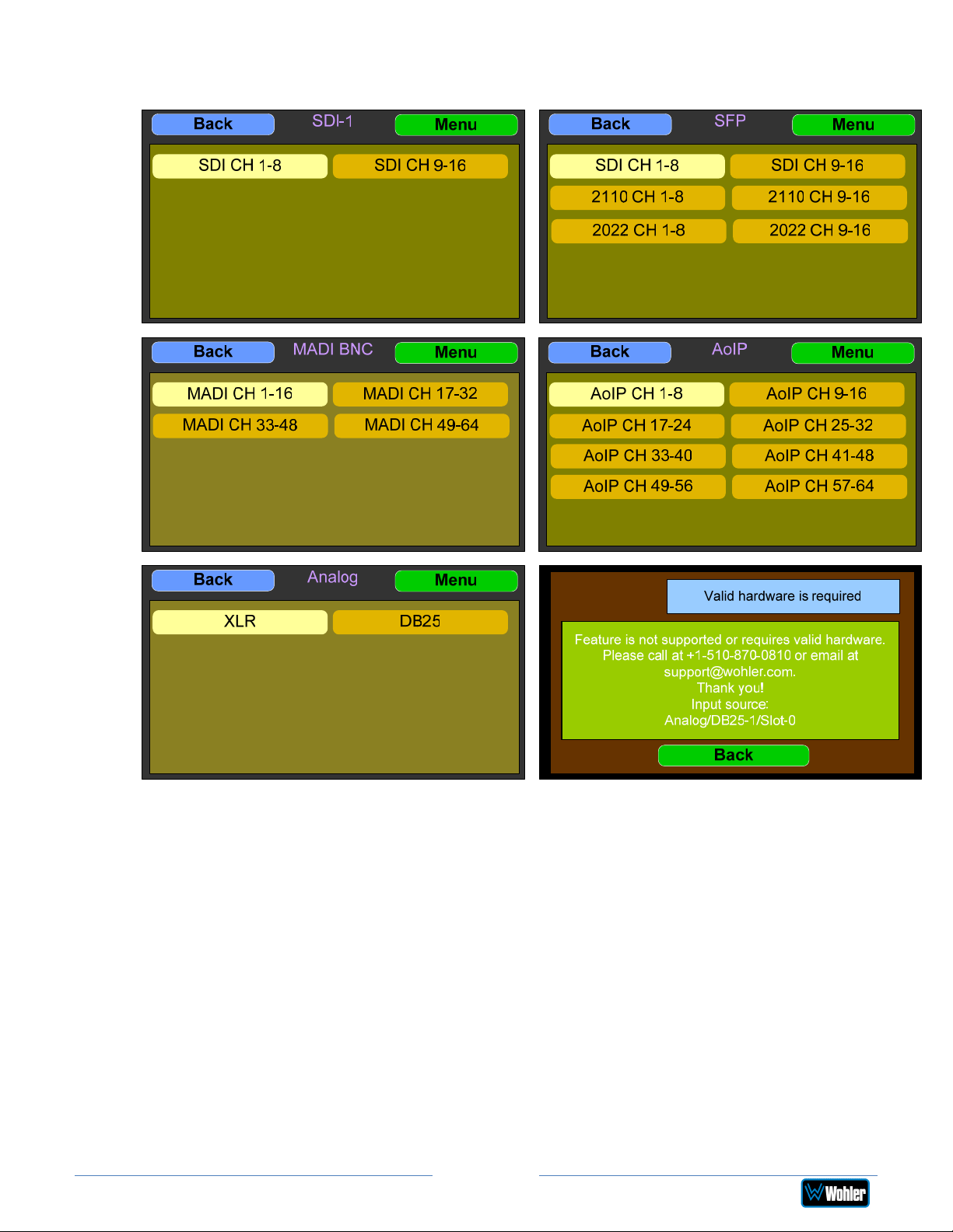
Figure 2-20: SDI, MADI, SFP, Analog, & AoIP Selection Screens:
Touch Back to return to the Source Select menu or touch Menu to return to the
Main Menu.
Presets
Presets are pre-arranged input and monitoring setups that can be used to monitor a
variety of combinations of inputs. They may be set up to allow quick and easy
selection of monitoring configurations for various productions and situations. If you
have not set up any Presets, use the Configure Presets page in the Web GUI to do
so. Refer to Chapter 4. Or, if you prefer not to set up any Presets, simply monitor
the sources directly using the Source Select button in the Menu.
iAM2-8
Page 31
Page 32
Preset Favorites
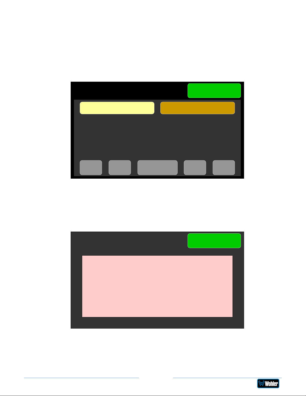
Touch the Preset Favorites button to display the Preset Favorites screen. This
shows the Presets that you have designated as Favorites. Refer to the Dashboard
section of Chapter 4. Generally, these are frequently used Presets that you want to
separate out from the possibly many other Presets in the system. The Preset
Favorites screen is shown in Figure 2-21.
Figure 2-21: Preset Favorites Screen
Preset Favorites
Menu
Comedy Time Satire Today
<- <<- ->> ->1 of 1
In this screen, the currently selected Preset is shown in bright yellow. Touch any
Preset to select it. To exit this screen without making a selection, touch Menu. If
no Favorite Presets have been designated, this screen will appear as shown in
Figure 2-22.
Figure 2-22: Preset Favorites Screen - No Favorites
iAM2-8
Preset Favorites
No favorite presets have been created.
You can create favorite presets using the
Menu
iAM2-8 web interface.
Page 32
Page 33
All Presets
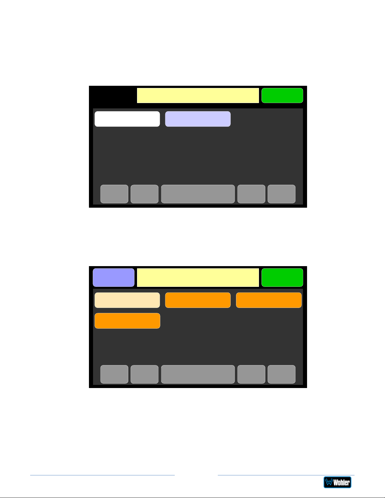
Touch the All Presets button to display the All Presets Group Selection screen as
shown in Figure 2-23. If no Presets have been created, the screen in Figure 2-25
appears instead.
Figure 2-23: All Presets Screen - Group Selection
Active Preset: Operator 1 / Comedy
Menu
Operator 1 Operator 2
<-
<<-
->> ->Group: Page 1 of 1
The Presets are normally arranged into Groups. Use this screen to select which
Preset-containing Group to examine. After selecting one of the Groups, the Preset
Selection screen shown in Figure 2-24 is shown.
Figure 2-24: All Presets Screen - Preset Selection
Groups
Group: Operator 1
Menu
To select a Preset, touch the associated button. After a quick 2-second delay, the
metering screen will display the channels contained in that source.
To return to the All Presets Group Selection screen instead, touch the Groups
button. To return to the Menu without making a selection, touch the Menu button.
iAM2-8
First Show Late Show Evening News
Good Morning!
<-
<<-
Page 33
->> ->Preset: Page 1 of 1
Page 34
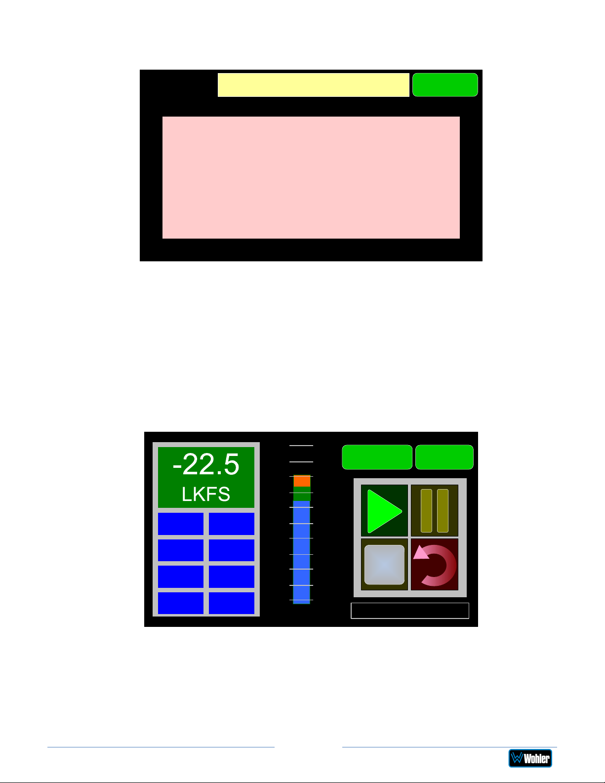
Figure 2-25: All Presets Screen - No Presets
Input Source: SDI-1
Menu
No presets have been created.
You can use source select
OR
Create presets using the
iAM2-8 web interface.
To return to the Menu from this screen, touch the Menu button.
Loudness Meter
Touch the Loudness Meter button to reach the Loudness Meter Screen. The
Loudness Meter Screen is a more detailed view of the Loudness Measurement. It is
displayed along with the channel meter screen. Touching the Loudness Menu button
followed by the Loudness Meter button proceeds to the Loudness Meter Screen, as
shown in Figure 2-26.
Figure 2-26: Loudness Meter Screen
+9
MenuAudio Meters
LRA 0.1
PROG -21.5
MAX -20.1
TP -20.0
-24
LU-M
+6
+3
Ref
-3
-6
-9
-12
-15
-18
-21
1: Stereo 2.0 #1
Note: In order to calculate loudness accurately, it is crucial that you correctly set
the Channel Function for each channel. Depending upon the designated function of
each channel, its signal levels will contribute differently to the Loudness calculation.
Refer to the Configuration | System Preference | Loudness Configuration tab
in the Web GUI.
The following data is available on the Loudness Meter Screen:
Page 34
iAM2-8
Page 35
The Program Loudness (shown as -22.5 LKFS in the figure above) is shown digitally
at the upper left of the screen as well as on the meter in the center. At the base of
the meter in the center, one of three indications appears:
1. LU-M: This means that the Loudness Window is set to Momentary.
2. LU-S: This means that the Loudness Window is set to Short Term.
3. LU-C: This means that the Loudness Window is set to Custom. The Loudness
Window is set in the Loudness tab in the Web GUI.
The LU Meter scale colors have the following meaning:
1. Blue: Loudness is lower than the Reference Level by the Alarm Tolerance.
2. Green: Loudness is within the Alarm Tolerance.
3. Orange: Loudness is greater than the Alarm Tolerance.
Below the digital Loudness meter, in the left column, the following parameters are
also displayed:
1. The Loudness RAnge (LRA) is the measure of variation between the
calculated loudest and softest passage over the program period (shown as
LRA -0.1 above).
2. The Average Loudness is the average of all calculated loudness
measurements made over the Program period (shown as PROG - 20.5
above).
3. The Maximum Loudness is the maximum calculated loudness over the
program period (shown as MAX -20.1 above).
4. The Maximum True Peak Loudness is the absolute loudest peak waveform
over the program period (shown as TP -20.0 above).
Note: Further and more detailed descriptions of all of the above Loudness terms
may be found in the ITU-R BS.1770-3 loudness standard.
The controls available on the Loudness Meter Screen are:
1. Cluster Select: The name of the monitored channel cluster is shown at the
bottom right of the screen. Rotate the Source knob to select any other
monitored channel cluster. Changing clusters with this control will reset the
loudness readings and start a new calculation on the newly selected cluster.
2. Start: When Manual Mode is selected in the Loudness Settings
screen, from a stopped condition, the Start button will reset the
gathered loudness data and begin a new reading. From a paused
condition, data will not reset as monitoring is resumed.
3. Pause: The Pause button will temporarily stop or continue
gathering loudness data. Data will not be reset using this control.
4. Reset: The Reset button will reset the gathered loudness data. If
it is pressed while a loudness measurement is in progress, a new
reading will then immediately begin.
5. Stop: When Manual Mode is selected in the Loudness Settings
screen, the Stop button will stop gathering loudness data. Data will
be held for viewing and not be reset using this control.
6. Back: Touching the Back button to go to the Loudness Menu.
Page 35
iAM2-8
Page 36
7. Audio Meters: Touching the Audio Meters button will proceed to the Audio
Meters screen.
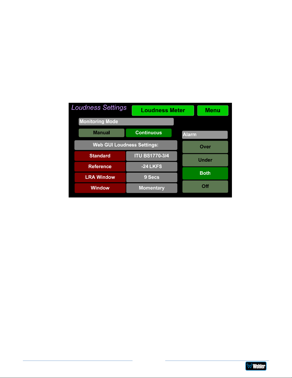
Loudness Settings
Touch the Loudness Settings button to display the Loudness Settings screen.
This screen allows you to change between Manual and Continuous Monitoring
Modes, and also to set the Alarm mode. It also provides a summary of various
Loudness settings, as set in the Configuration | System Preference | Loudness
Configuration tab of the Web GUI. Refer to Figure 2-27.
Figure 2-27: Loudness Settings Screen
The controls and information available on the Loudness Meter Screen are:
Monitoring Mode:
1. Manual: Touch the Manual button to enable Manual Mode. This allows you to
measure the loudness of a specific program or segment of a program, such
as a commercial. In this mode, the Start and Stop button on the Loudness
Meter screen can be manually used to begin and end a loudness
measurement interval. The reading for that interval is then held on the
Loudness Meter.
2. Continuous: Touch the Continuous button to enable Continuous Mode. In
this mode, loudness readings are continually made. The Stop button on the
Loudness Meter screen is not active.
Alarm:
1. Over: The Alarm indication will only appear when Loudness has exceeded
the Reference Level by the Tolerance amount.
2. Under: The Alarm indication will only appear when Loudness is below the
Reference Level by the Tolerance amount.
3. Both: The Alarm indication will only appear when Loudness has exceeded or
is below the Reference Level by the Tolerance amount.
4. Off: The Alarm indication will not appear.
Page 36
iAM2-8
Page 37
Web GUI Loudness Settings: These settings are included on this screen for
reference only. They cannot be changed on this screen.
1. Standard: This is the loudness standard by which the loudness calculation is
made.
2. Reference: This is the set point in the loudness measurement about which
the determination is made as to whether an alarm should be displayed.
3. LRA Window: This is a moving window of time over which the loudness
measurement is made.
4. Window: This may be set to Momentary, Short, or one of 22 values,
ranging from one second to two hours.
Note: Further and more detailed descriptions of all of the above Loudness terms
may be found in the ITU-R BS.1770-3 loudness standard.
When you have completed reviewing or changing the settings, touch the Loudness
Meters button to go the Loudness Meters screen, or touch the Back button to
return to the Loudness menu.
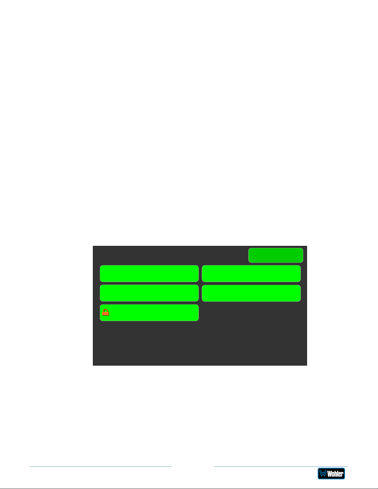
System Options Menu
Touching System Options in the Main Menu proceeds to the System Options
menu, which is an intermediate menu leading to other screens. This menu is shown
in Figure 2-28.
Figure 2-28: System Options Menu
System Options
Network Settings System Reboot
System Update
Passcode Settings
Touch Menu to exit this menu.
Menu
Factory Reset
Page 37
iAM2-8
Page 38
Network Settings
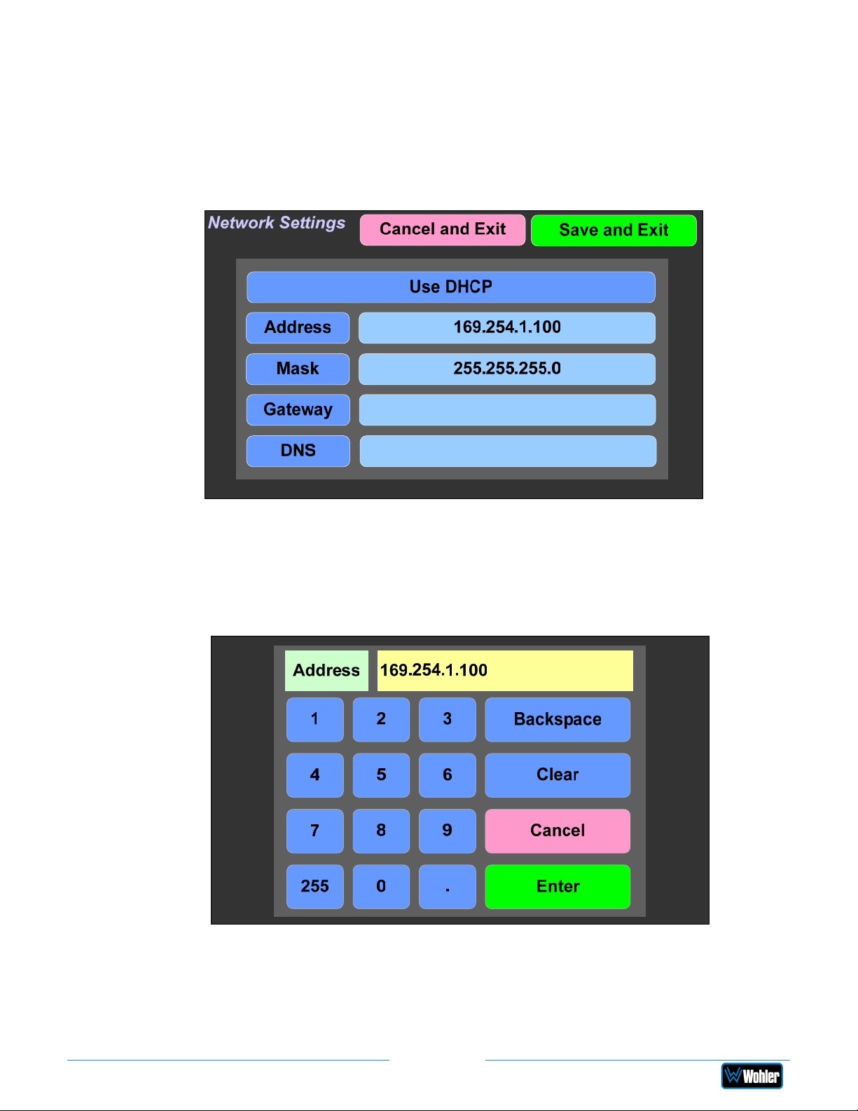
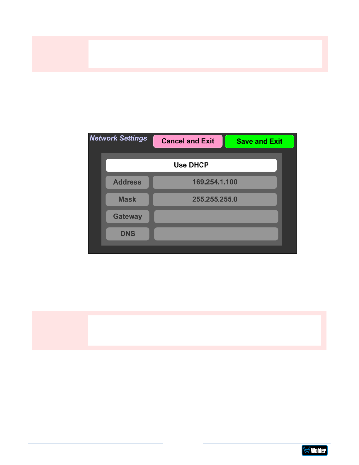
Touch the Network Settings selection on the System Options Menu displays the
Network Settings menu as shown in Figure 2-29. This screen lets you view or
change the product IP, the Net Mask, Gateway and DNS. It also lets you switch
between a static (fixed) or a dynamic (DHCP) network address.
Figure 2-29: Network Settings Screen
1. To change the IP Address, Net Mask, Gateway, or DNS, tap the item you
would like to change. A keypad will appear, as shown in Figure 2-30.
Figure 2-30: Network Configuration: Setting Change
2. Touch the digits to be entered and then touch the Enter button. The Clear
button may be touched to erase any mistyped digits.
3. Now repeat steps 1 and 2 until you have replaced all of the necessary digits.
4. To save the newly entered address, touch the Enter button. Touch the
Page 38
iAM2-8
Page 39
Important:
, so make sure you want to
The system will not need to reboot
this action before taking it. The system does not need to reboot before
Important:
To change from a static (fixed) to a dynamic (DHCP) network address, touch the
DHCP button. The screen will change, as shown in Figure 2-31. To change back to
a static (fixed) network address, touch the DHCP button again. The colors of the
buttons will return to the ones depicted in Figure 2-29.
Cancel button to return to the previous screen without saving any changes.
There is no confirmation for Save, so make sure you want to perform
it is once again ready for operation.
Figure 2-31: Network Settings: DHCP
1. To complete the network addressing scheme change, touch the Save button.
This will save the changes you selected.
2. Touch the Cancel button to return to the previous screen without saving any
changes.
There is no confirmation for Save and Exit
perform this action before taking it.
before it is once again ready for operation.
iAM2-8
Page 39
Page 40
System Reboot
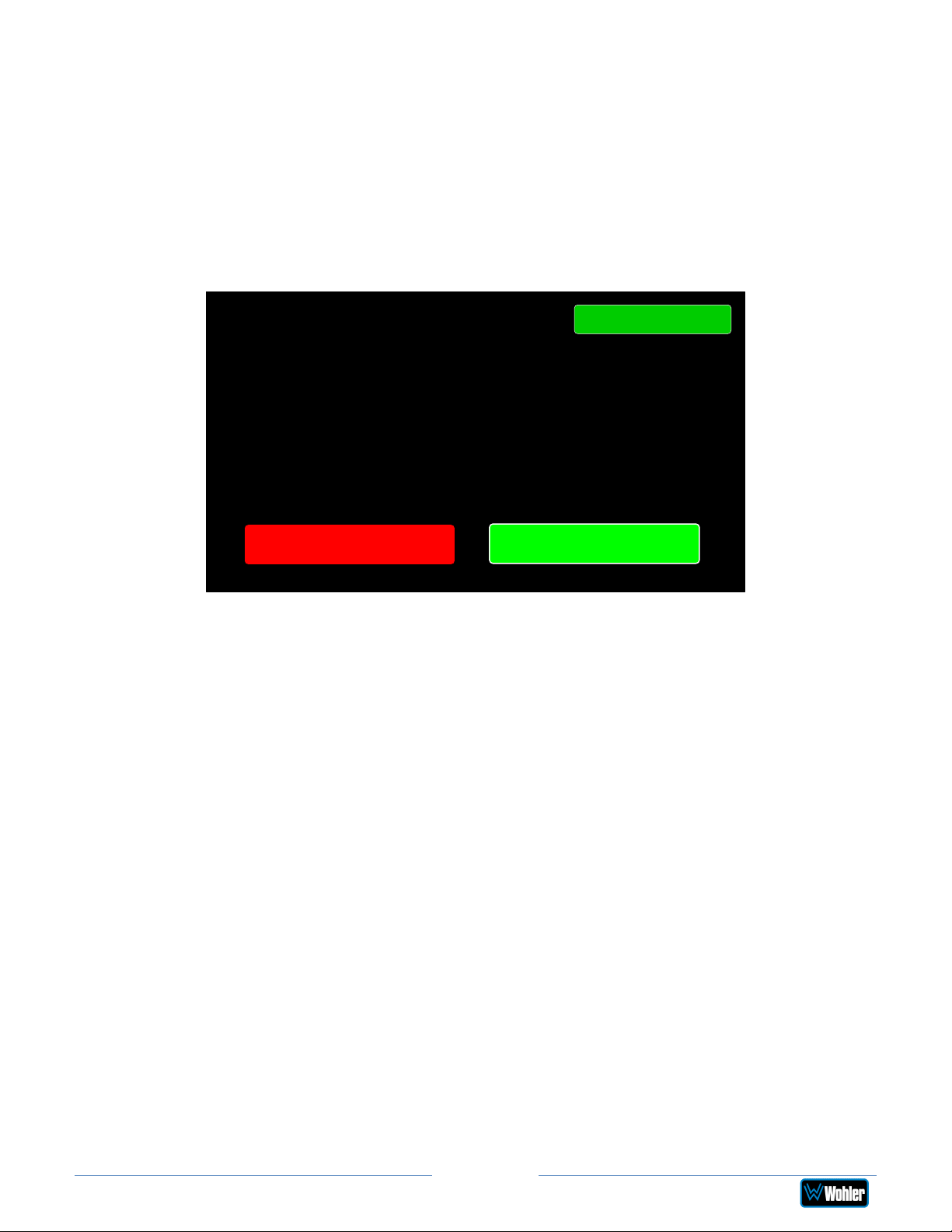
Touching the System Reboot selection on the System Options Menu displays the
System Reboot screen as shown in Figure 2-32. This function is normally only
used upon request from Wohler Technical Service to troubleshoot or correct an
issue.
The System Reboot function should be used with a bit of forethought. It puts the
system out of service for several minutes while it is rebooting.
Figure 2-32: System Reboot
System Reboot
Are you sure?
You wish to Reboot the System?
Back
Yes
No
If you have any doubt as to whether you should press Yes, press Back or No
instead, and contact Wohler Technical Service for advice. Pressing Back or No will
return you to the System Options menu.
Page 40
iAM2-8
Page 41
System Update
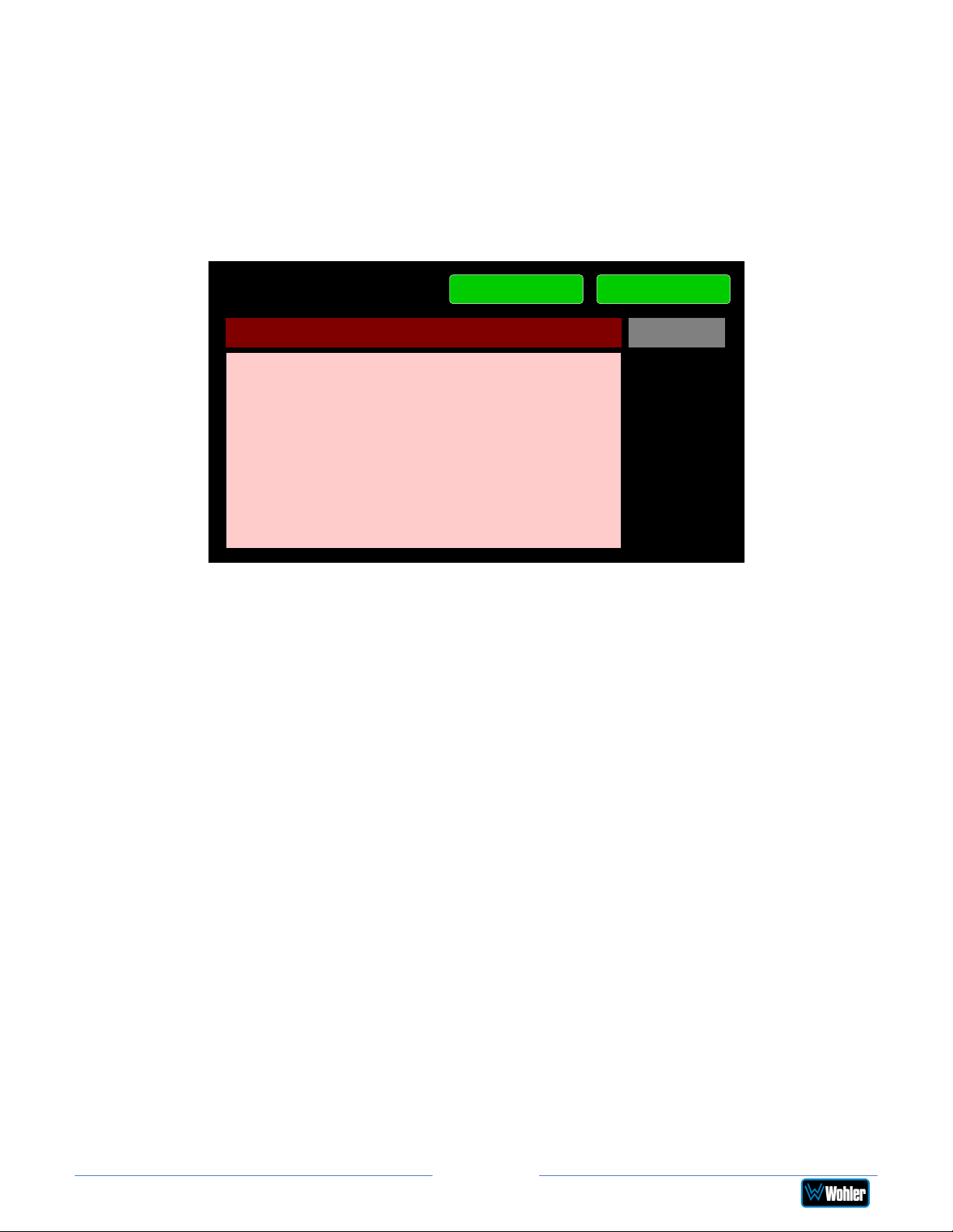
Touching the System Update selection in the System Options Menu displays
System Update screen as shown in Figure 2-33, showing the current software
version of the product. To update the system software locally from the iAM2-8 front
panel, follow the procedure in the Local Update from the Front Panel section of
Appendix A.
Figure 2-33: System Update Screen
System Update
Upgrading System.
There is no USB mounted.
Refresh
Software Version 0.0-0
Back
If you have just inserted a flash drive with a valid software upgrade package, press
Refresh to see that package.
Touch the Back button return to the System Options Menu.
Page 41
iAM2-8
Page 42
Factory Reset
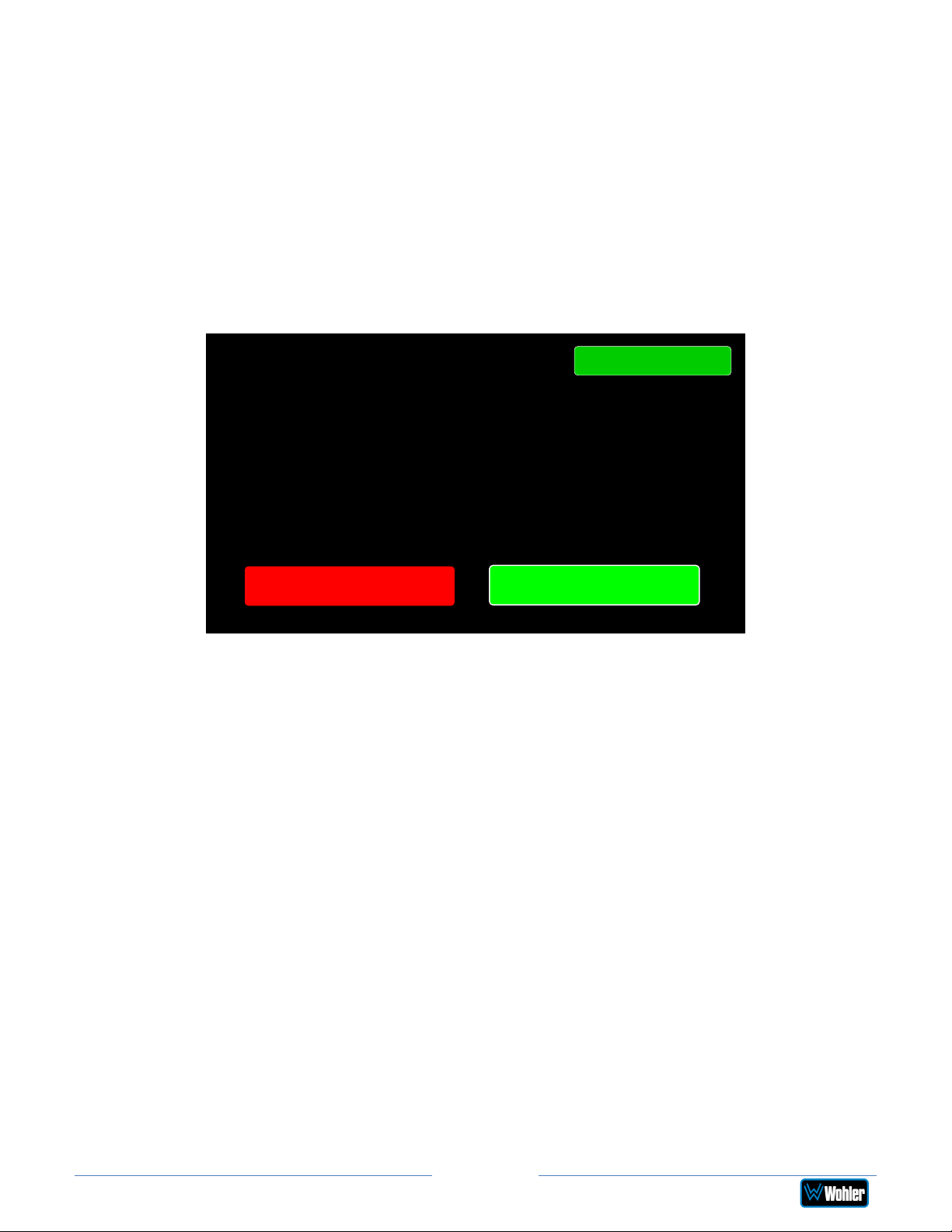
Touching the Factory Reset selection in the System Options menu displays the
Factory Reset screen as shown in Figure 2-34. Because of the large change this
function is about to make to the product, it asks for you for verification that you
really want to proceed.
The Factory Reset function should be used with caution. It deletes all of the
settings you have programmed into the system. It returns the system to the way it
was when received new from the factory. After using this function, you will need to
use the Wohler Web GUI to reprogram everything from the start.
Figure 2-34: Factory Reset
Factory Reset
Set system to factory
default settings?
Back
Yes
No
Note: Factory Reset will also reset your IP address to the default one. After a
Factory Reset, the IP Settings will need to be updated. The default IP address for
the unit is determined based upon the Mac address. It is 169.254.1.xx where xx is
the last octet of the management Mac address. For example, if the Mac address is
b4:ed:54:d0:04:28 then the IP address would be 169.254.1.40 (40 is the decimal
equivalent for the last octet of Mac address 28.)
If you have any doubt as to whether you should press Yes, press Back or No
instead, and contact Wohler Technical Service for advice. Pressing Back or No will
return you to the System Options menu.
Page 42
iAM2-8
Page 43
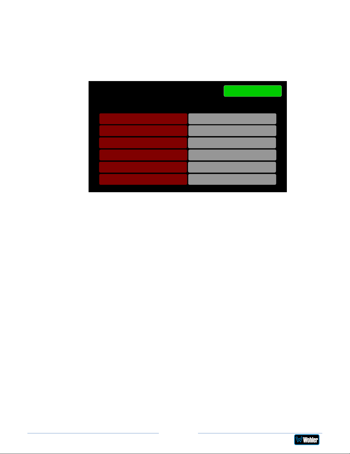
System Details
Touching the System Details selection in the System Options menu displays the
System Details screen as shown in Figure 2-35. This screen lets you view the
product Serial Number, Software Version, and various other information.
Figure 2-35: System Details Screen
System Details
Menu
System State / Mode
System IP Address
Valid / Normal
169.254.1.100
Software 1.0.7
Serial Number 000000
MAC Address b4:ed:54:d0:07:64
Option Card Not Installed
The information shown on this screen is read only and cannot be changed.
Touch Menu to exit this screen.
Page 43
iAM2-8
Page 44
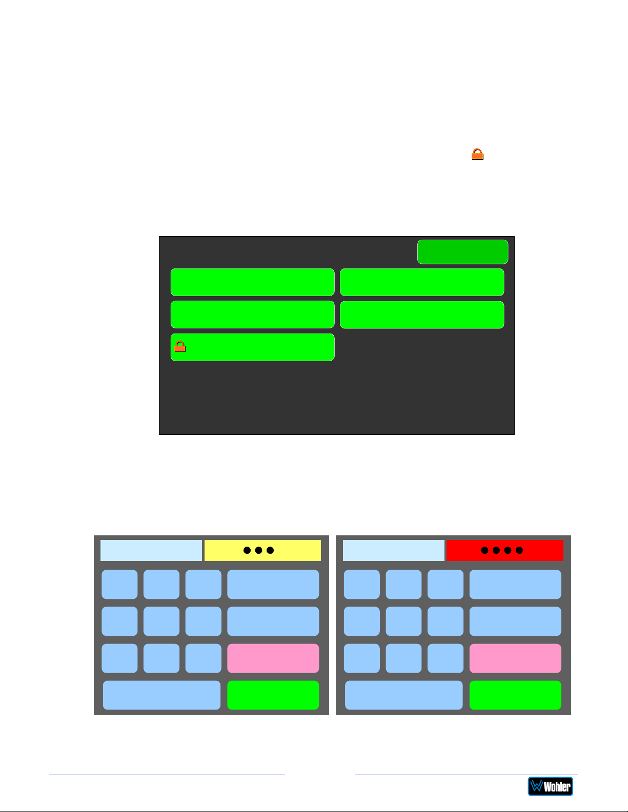
Passcode Settings
To prevent accidental or unauthorized changing of critical settings in some of the
menus, it is possible to block or restrict access to various menus. The Wohler Web
GUI can be used to limit access to the menus of your choice. Refer to Chapter 4,
the Front Panel Configuration tab of System Preferences.
The iAM2-8 contains a Passcode Settings screen. Access to this screen is always
protected by a unique Passcode, which you can set. Note that the protection of the
Passcode Settings selection is indicated by an orange lock icon: The
Passcode Settings button on the System Options screen contains this icon, as
shown in Figure 2-36. The factory default Passcode is 0-0-0-0.
Figure 2-36: System Options - Passcode Settings Lock
System Options
Menu
Network Settings System Reboot
System Update
Factory Reset
Passcode Settings
Touching the Passcode Settings selection in the System Options menu proceeds
to the Passcode Entry screen as shown in the left image of Figure 2-37.
Figure 2-37: Passcode Entry Screen
Enter Passcode
1
2
3
Backspace
Enter Passcode
1
2
3
Backspace
4
7
Enter the Passcode on the keypad and touch Enter. The numbers will display as
5
8
0
6
9
Clear
Cancel
Enter
Page 44
4
7
5
8
0
6
9
Clear
Cancel
Enter
iAM2-8
Page 45
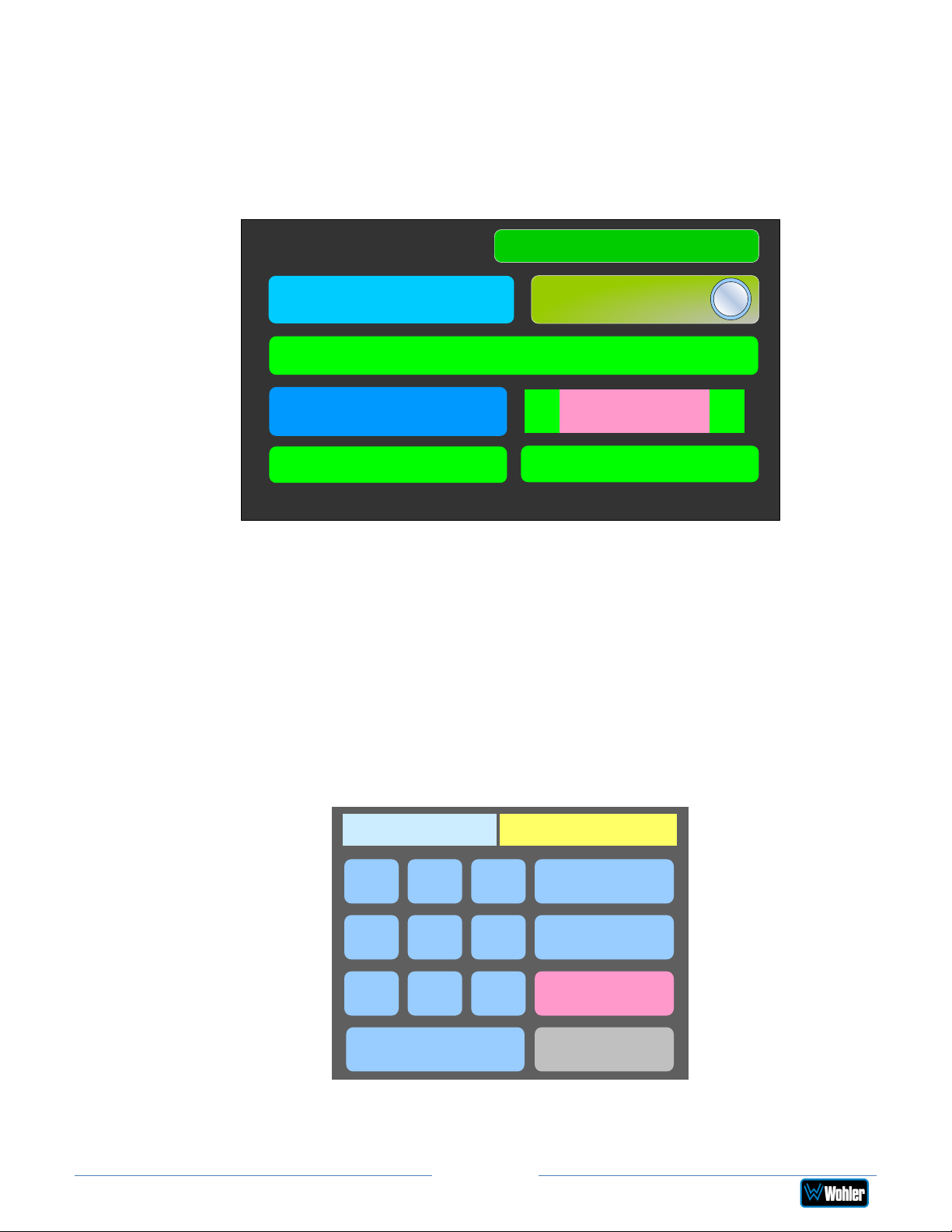
bullets in the field. If you enter the wrong Passcode, the entry field will turn red, as
shown on the right image of Figure 2-37. Press Clear and try again.
When you have successfully entered the Passcode, the Passcode Settings screen
will appear, as shown in Figure 2-38.
Figure 2-38: Passcode Settings Screen
Passcode Settings
Cancel
Restricted
Access
Set Passcode
On
Type
< >
Apply Default
The functions on this screen are as follows:
Restricted Access: This switch will turn ON or OFF protection or blocking of any
menus, except for the Passcode Settings menu, which is always Passcode
protected.
Set Passcode: Touching this button proceeds to a keypad which allows you to
enter a new Passcode. The screen shown in Figure 2-39 will appear. The Passcode
can be any 4-digit number. Touch Enter to save the new Passcode or touch Cancel
to keep the previous Passcode. Be sure to save the Passcode in a safe place for
future reference.
Passcode
Access
Save
Figure 2-39: Set Passcode Screen
Set Passcode
1
4
7
2
5
8
0
Page 45
3
6
9
Backspace
Clear
Cancel
Enter
iAM2-8
Page 46
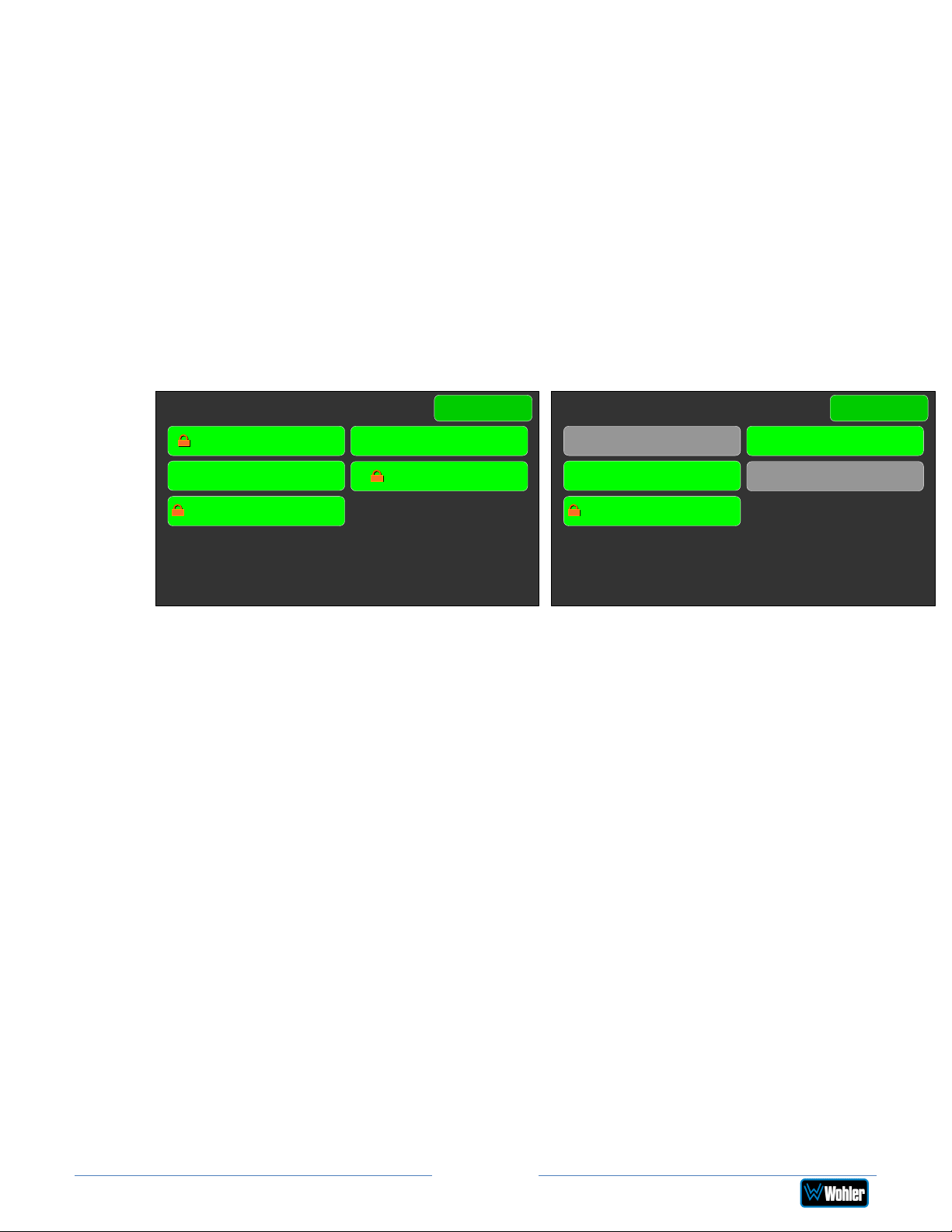
Type: Select the type of disabled button appearance using the Type button. The
choices are:
Passcode Access: The Passcode protected function buttons include a small
orange padlock icon within the buttons. This is shown in the left image of
Figure 2-40. Touching these buttons will cause a Passcode entry screen to
appear, as shown in the left image of Figure 2-37. The correct Passcode must
be entered to proceed.
No Access: If the function buttons are protected by No Access, the buttons
are grayed out and non-functional, as shown in the right image of Figure 2-
40. These buttons cannot be accessed at all unless the restricted protection
is removed by switching OFF the Restricted Access setting in this menu.
Figure 2-40: Examples of Menu Protection
Passcode Access: No Access:
System Options
Menu
System Options
Menu
Network Settings System Reboot
System Update
Passcode Settings
Factory Reset
Network Settings System Reboot
System Update
Passcode Settings
Factory Reset
Apply Default: Touching this button returns the settings in this screen to the
factory default values. The Passcode becomes 0-0-0-0.
Save: Touching this button saves the settings made in this screen and returns to
the System Options screen.
Forgotten Passcode
Although the Passcode should be remembered or securely noted somewhere, it can
happen that it is forgotten. This can be remedied by performing a Factory Reset
from the Wohler Web GUI. Unfortunately, this will also erase all of the menu
settings. You may also contact Wohler Technical Service for help.
Page 46
iAM2-8
Page 47
8
channels from:
CHAPTER 3:
Table 3–1: iAM2-8 Specifications
Specification
Power Requirements
Power Consumption 65 Watts
Dimensions
(H x W x D)
Shipping/Net Weight 12 lbs. (5.44 kg) / 7.95 lbs. (3.61 kg)
Supplied Accessories AC Power Cord
Display Type Two 4.3" Capacitive Touchscreen LCDs
Screen Resolution 480H x 272V
Viewing Angle 160 (H) x 160 (V)
Audio Channels 8 Max
Level Meters Simultaneous Average & PPM
Level Meter Scale
Technical Info
100 VAC to 240 VAC ± 10%, 50/60Hz
3.5” x 19” x 5.5” (88mm x 483mm x
140mm), standard 19” rack mounting
Choice of AES, BBC, DIN, EBU, EXTVU,
NORDIC, or VU
Values/Domains
Sample Rate 48kHz
De-Multiplexing
SDI Inputs / Outputs
MADI Inputs / Outputs
SMPTE 2022-6 Receiver
SMPTE 2110 Receiver
• 16-channel SD/HD/3G-SDI
• 64-channel AES10 MADI
•
2 SDI Inputs and 1 SDI Output
Optional – Single SFP Transceiver:
• HD-BNC Coax 3G/HD/SD-SDI
• Multi-Mode Fiber: 1 SI Optical
SC-Connector, 1300nm
• Single-Mode Fiber: 1 SI Optical SC
Connector, 1310nm
•
1 MADI BNC, Standard Coax I/O
Optional – SFP Transceiver:
• Multi-Mode Fiber: 1 MADI Optical
SC-Connector, 1300nm
• Single-Mode Fiber: 1 MADI Optical
SC Connector, 1310nm
Optional - SFP Receiver:
• Multi-Mode Fiber: LC Connectors,
850nm
Optional - SFP Receiver:
• Multi-Mode Fiber: LC Connectors,
850nm
iAM2-8
Page 47
Page 48
<0.0
1%
THD+N
Analog Output
Reference
Headphone Out
-
Stereo
Specification
Values/Domains
Cable/Fiber Length (max)
COAX (such as Belden 1694A): > 150 m
Single-mode fiber: 10 km
AES Inputs
AES Outputs
Upgrades
SDI Input Termination
AES/EBU Input Termination
AES/EBU/MADI Sampling
Rate
Analog Inputs - Stereo
Analog Input Impedance
Analog Outputs - Stereo
Analog Output Frequency
Response
8 AES channels on HD-15 are optional
8 AES channels on HD-15
Via USB interface
75Ω unbalanced
75Ω unbalanced
48 kHz
XLR-3 Female, balanced
40kΩ balanced
XLR-3 Male, balanced +28 dBU max
40 Hz to 20 kHz (± 1dB)
Analog Output Distortion
Analog Output Dynamic
Range
Level
> 100 dB
-20 dBFS = +4 ± 1.0 dBU
Internal Speakers - Stereo 3” Full Range
Peak Acoustic Output 104 dBA SPL (@ 2 feet)
Hum and Noise Better than -75 dB below full output
Power Output 15 Watts RMS, 30 Watts peak (each side)
Acoustic Frequency
Response
60 Hz to 16 kHz (± 5 dB)
Stereo, 40 Hz to 20 kHz (± 1 dB)
Headphone Load 8Ω to 150Ω
iAM2-8
Page 48
Page 49
to
Enables decoding and monitoring of 4 x AES
Table 3–2: iAM2-8 I/O Options
Option
SFP-Madi-MMFiber
SFP-Madi-SMFiber
Part #
829081
829082
SFP-SDI 829089
SFP-SDI-Fiber 829084
SFP-2022-6 829088
SFP-2110 829086
Description
MADI optical fiber transceiver. Multi-Mode, LC
(fiber) connectors. SFP module with software
activation key.
MADI optical fiber transceiver. Single-Mode,
LC (fiber) connectors. SFP module with
software activation key.
3G/HD/SD-SDI single video receiver with
active loopback, HD-BNC connectors. SFP
module with software activation key.
3G/HD/SD-SDI video SFP optical input; LC
(fiber) connectors; Single-Mode Receiver,
Medium Haul, Non-MSA, no output.
SMTPE 2022-6 receiver; Multi-Mode 850 NM,
LC (fiber) connectors. SFP module with
software activation key. Use MN-Set** to
configure SFP.
SMTPE 2110 receiver; Multi-Mode 850 NM, LC
(fiber) connectors. SFP module with software
activation key. Use MN-Set** to configure
SFP.
SMTPE 2110 or 2022-6 receiver; Multi-Mode
SFP2110+2022-6
829087
850 NM, LC (fiber) connectors. SFP module
with software activation key. Use MN-Set**
configure SFP.
OPT-AES
829080
inputs and outputs on two HD-15
connectors. Requires a software activation
key.
Enables decoding and monitoring of 1 x
OPT-MADI 829092
OPT-OUTPUTROUTING
829159
MADI64 input. BNC connectors.
software activation key.
Requires a
Enables the flexibility to route signals from
any inputs to various outputs.
**MN-Set is configuration software that is necessary so that you can set up this
module. It is available at no cost either from its manufacturer, Embrionix, or by
contacting Wohler Technologies Technical Service.
iAM2-8
Page 49
Page 50
ANLG/TOS
ludes AoIP card. Enables 2 x
Table 3–3: iAM2-8 Option Cards
Option
OPT-DOLBY
D, DD+, E
OPT(iVAM)
OPT-DANTE
(iVAM)
OPT-RAVENNA
64 (iVAM)
Part #
829167
829170
829171
829172
OPT-SFP 829179
Description
Enables decoding and monitoring of Dolby®
D, DD+, & E streams. Hardware card with
software activation key.
Enable monitoring of 8 Analog channels on
DB-25. TOSLINK included.
Enable decoding and monitoring of DanteTM
input streams. Inc
RJ-45 ports for 2022-7 support (for Dante,
Ravenna and 2110-30) + SFP cage allowing
MM and SM SFP’s for AoIP Signals. TOSLINK
included.
Enable monitoring of up to 64 RavennaTM /
AES67 input. NMOS support. TOSLINK
included.
Adds two additional 3G inputs to 3G products,
or two 12G inputs to 12G products.
iAM2-8
Page 50
Page 51
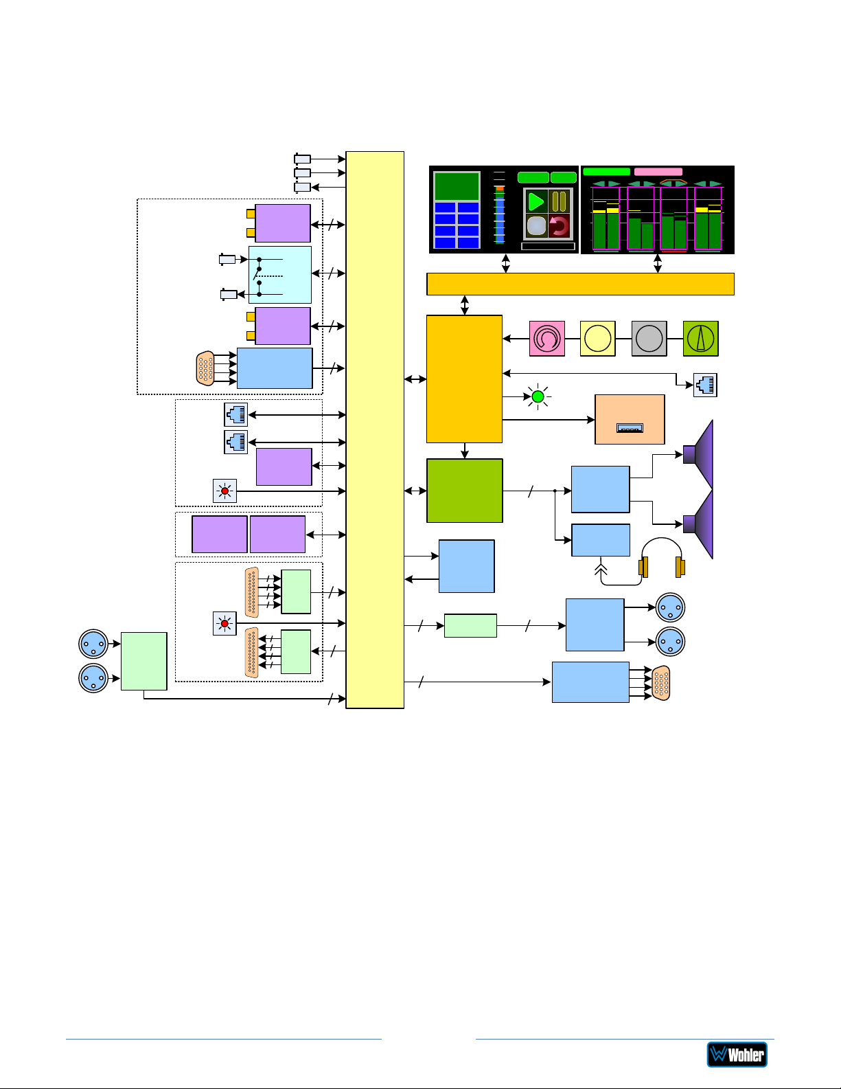
Figure 3–1: iAM2-8 Block Diagram
Monitoring
Upgrades:
2110
2022-6
3G-SDI
Reclocked MADI
Channel Pair
Inputs 1 – 4
on HD-15
AoIP Option Card:
Dante
Ravenna
2110-30
OPT-SFP:
2 SFP Cages
Analog Option Card:
8 Balanced Inputs
8 Balanced Outputs
Toslink SPDIF
Balanced Analog
Stereo Input Pair
L
Stereo
A/D
R
Converter
3G-SDI Input 1
3G-SDI Input 2
MADI
3G-SDI Output
Input
Input
SFP Cage for
Optional
Module
Optional MADI
SFP Cage for
Optional
MADI
Module
Audio & Video from SDI 1, 2, or SFP
Active Loopback
BNC Input
BNC Output
Active Loopback
AES
AES Receiver
Primary
1 GB ENET
Secondary
1 GB ENET
Toslink
(SPDIF)
Input
Additional
SFP Cage 1
Toslink
(SPDIF)
Input
AoIP SFP
Cage for
Fiber Module
Additional
SFP Cage 2
L-R
L-R
Power
4
Stereo
ADCs
4
Stereo
DACs
16
64
64
8
8
8
2
Input
Selector
and
Router
Touchscreens for Audio Meters / Loudness / Control
-22.5
LKFS
LRA 0.1
PROG -21.5
MAX -20.1
TP -20.0
+9
Audio Meters
+6
+3
-24
Ref
-3
-6
-9
-12
-15
-18
-21
1: Stereo 2.0 #1
LU-M
Menu
LKFS-M : -24.6
-00
-20
-30
-40
-60
1
Graphics / Touch Processors
Volume
/ Mute
Source
UI / System
Configuration
and Control
Audio Mixer,
Level, Tone,
and Delay
Power /
Status
S/W Updates /
2
Class D
Amplifier
Controls
Class AB
Optional
Amplifier
Dolby
D/DD+/E
Decoder
2
Stereo D/A
Converter
8
2
Balanced
Line
Drivers
AES Output
Drivers
2
S
t
e
r
e
o
Presets
USB
SDI-1
5
4
6
S
t
e
r
e
o
Balance
/ CenterChannel
Headphone
L
R
any Monitored
AES Channel Pair
Outputs 1 – 4 on HD-15
Audio from any
Monitored Source
73
8
S
t
e
r
e
o
Balanced
Analog
Stereo
Output Pair
Audio from
Source
-
00
S
t
-20
e
r
-30
e
-40
o
-60
Mgmt
Port
Left
Speaker
Right
Speaker
Page 51
iAM2-8
Page 52

CHAPTER 4: The iAM2-8 Web GUI
The self-contained iAM2-8 Web GUI allows you to customize the configuration of
the iAM2-8 to suit your needs. If the default configuration of the iAM2-8 suits your
needs and you prefer to use it that way, then you do not need to use the iAM2-8
Web GUI.
The iAM2-8 Web GUI also allows you to have a remote view of the Meter Screen.
Refer to the Audio Meters section in this chapter.
Web Browser / Control Device
Any web browser application running on any networked device such as desktop or
laptop computer, tablet or smart phone can be used with the iAM2-8 Web GUI.
Tablets with no network connector need to be linked to a copper LAN through a WiFi adapter.
Although they can be used, smart phones are not recommended because their
smaller screen size would require more scrolling, making operation challenging.
The Chrome® web browser is recommended for speed and compatibility.
First Time IP Assignments
The iAM2-8 can operate with a static (fixed) or dynamic (DHCP) IPv4 address. The
default address will be 169.254.1.x where x depends upon the MAC address of the
unit, when received from the factory or when switched from DHCP to static
addressing mode. There two basic types of connections that may be used to
connect the iAM2-8 to a web browser, a Peer-to-Peer Connection or a Network
Connection.
Peer-to-Peer Connection
The most straightforward way to connect the iAM2-8 to a web browser, free of
possible network conflicts, is to establish a static peer-to-peer connection between
the setup computer and the iAM2-8. A 10/100/1000 MHz Ethernet switch may be
used in between, but is not required.
Figure 4-1 shows an example of suitable address settings for the host computer in
a Windows control panel. For Peer-to-Peer the IP address of windows should be in
169.254.1.x domain.
Page 52
iAM2-8
Page 53
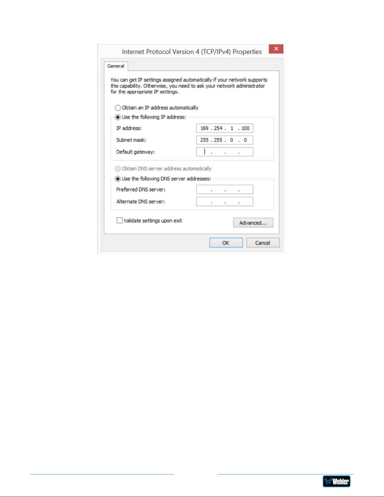
Figure 4–1: Host IP Settings
Close the control panel and reboot the host computer after making an IP address
change to be sure the change takes effect. Either reconnect to the installed network
or continue with this direct connection to access the iAM2-8 Web GUI.
Network Connection
When connected to a network, the iAM2-8 address will need to be changed to
another address in order to be compatible with the address assignments for that
particular network. Immediately after the host setup is complete, change the iAM28’s address. Make the corresponding address, mask and gateway changes in the
iAM2-8 Network Setup page. Refer to the Network Setup section which follows.
Otherwise set the iAM2-8 to DHCP address mode by checking the box for ‘Use
DHCP?’ in Network Setup and have your IT administrator assign rights and settings
for operation on the network. Allow enough time for your network’s DHCP server to
recognize a new network device and assign an address after booting.
The iAM2-8 uses link local addressing for its internal network, so no accommodation
for this need be made in the network.
Page 53
iAM2-8
Page 54
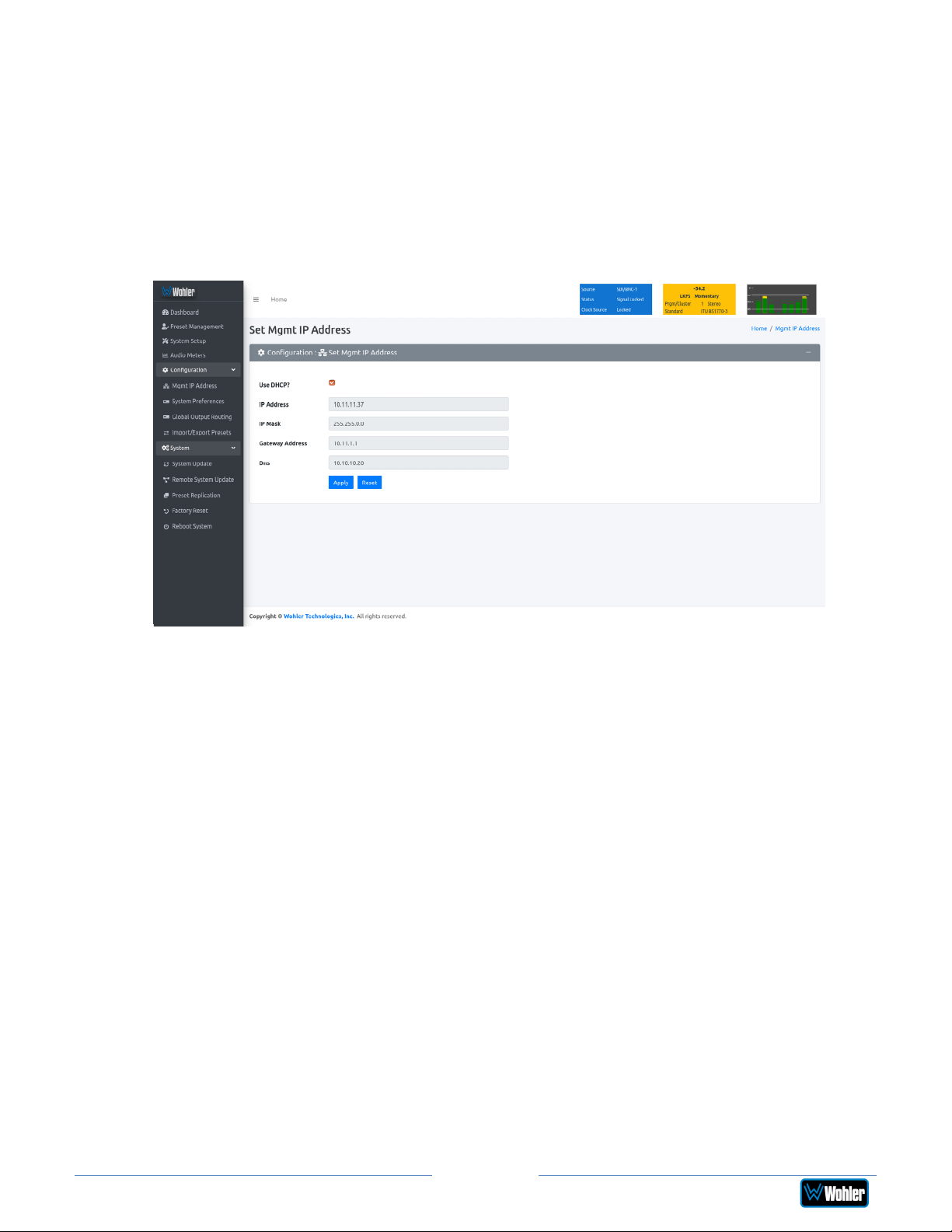
Network Setup
Make network IP Address changes for the local iAM2-8 Management (MGMT)
Port here.
iAM-AUDIO2-8
Figure 4–2: Set IP Addresses
The procedure for changing the IP Address information is as follows:
1. Use DHCP? Check this box if your network has a DHCP server and you want
to use dynamic addressing. Otherwise, you must enter static IP address
entries in the four fields which follow.
2. IP Address: Enter the network address. Leading zeroes are not required.
3. IP Mask: This should usually be 255.255.255.0 unless your network can
work across multiple subnets.
4. Gateway Address: This should usually be the same domain and subnet
address numbers as the IP Address, but with the last octet being .1.
5. DNS-nameserver: A default value is shown for reference only. DNS is not
normally required for basic static IP network configurations to work. Your IT
administrator will specify a value to work with mixed static/dynamic network
setups.
6. Apply: When you have made all of the necessary entries, press Apply to
apply the changes.
7. Reset: If you should start to make changes and then change your mind
about making them, press Reset to return the settings back to where they
were.
Page 54
iAM2-8
Page 55
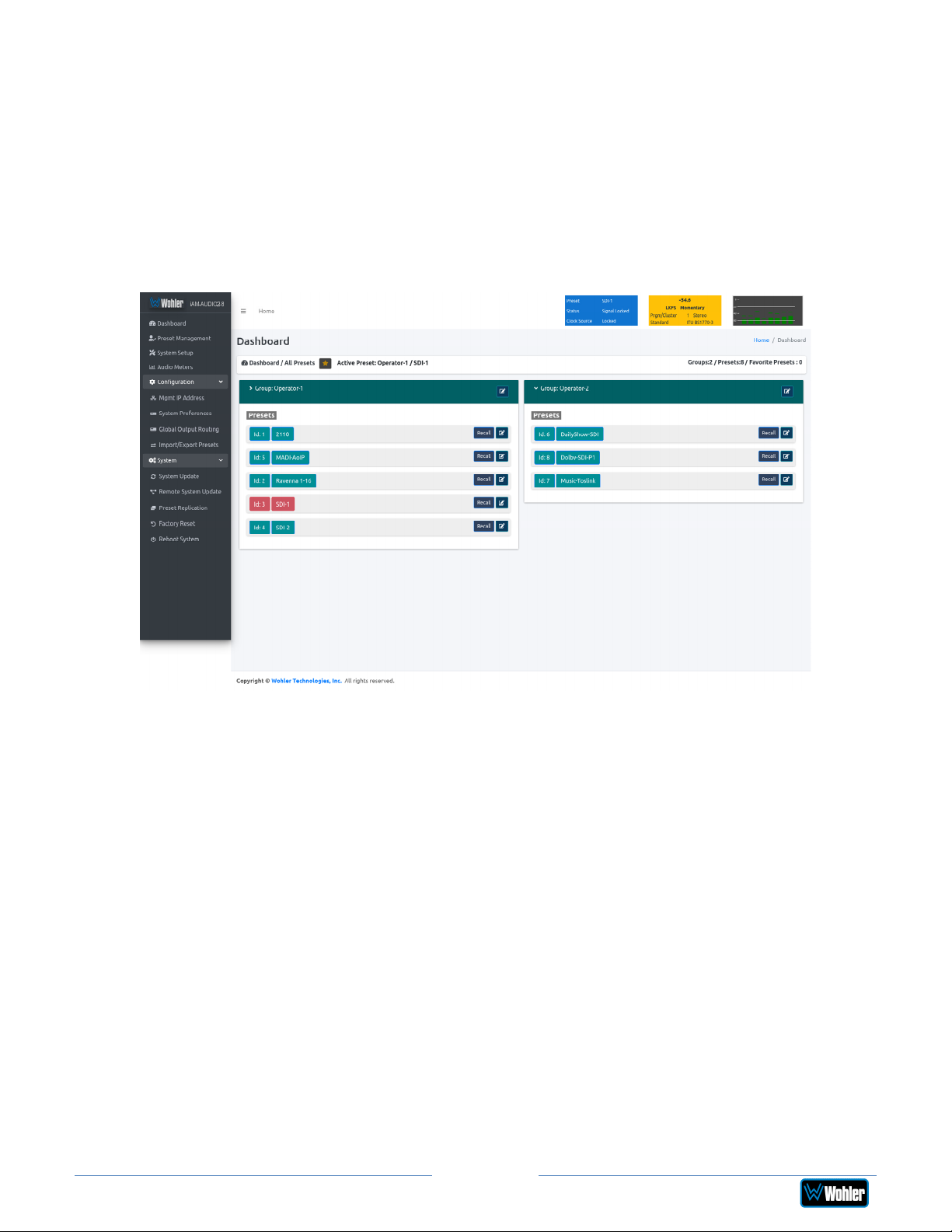
Dashboard
Throughout the Web GUI, pages are a click or two away using the list of selections
on the left side. The Dashboard page shows all of the available Preset
configurations at a glance. The iAM2-8 allows you to assign Presets to particular
groups. In Figure 4-3, two groups, Operator-1 and Operator-2 are shown.
Figure 4–3: Dashboard Preset Overview
To view all of the Presets within a group, click on that group.
Page 55
iAM2-8
Page 56
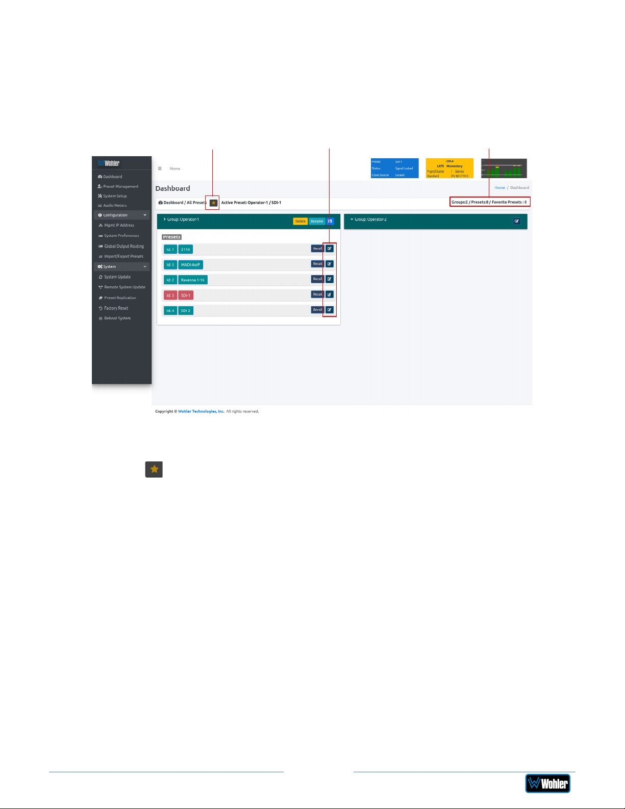
In Figure 4-4, it can be seen that there are five Presets in the Operator-1 group and
no Presets in the Operator-2 group. The currently selected active Preset for local
operation is shown in red. In Figure 4-4, this is the Preset named SDI-1.
Figure 4–4: Dashboard Preset Recall / Edit
iAM-AUDIO2-8
Favorite / All
Preset Selection
Edit Buttons
Group / Preset
Summary
A Group / Preset Summary is shown in the upper right of the screen. This enables
you to see the total number of Groups, Presets and Favorite Presets in the iAM2-8.
Use the button, as shown in Figure 4-4, to toggle between Favorite Presets or
All Presets.
Click the Recall button to recall a Preset. To Edit a Preset, click the Edit icon, as
shown in Figure 4-4, to the right of the associated Recall button.
After clicking the Preset Edit button, the screen shown in Figure 4-5 will appear.
Clicking a Group Edit button will cause the screen in Figure 4-6 to appear.
Page 56
iAM2-8
Page 57
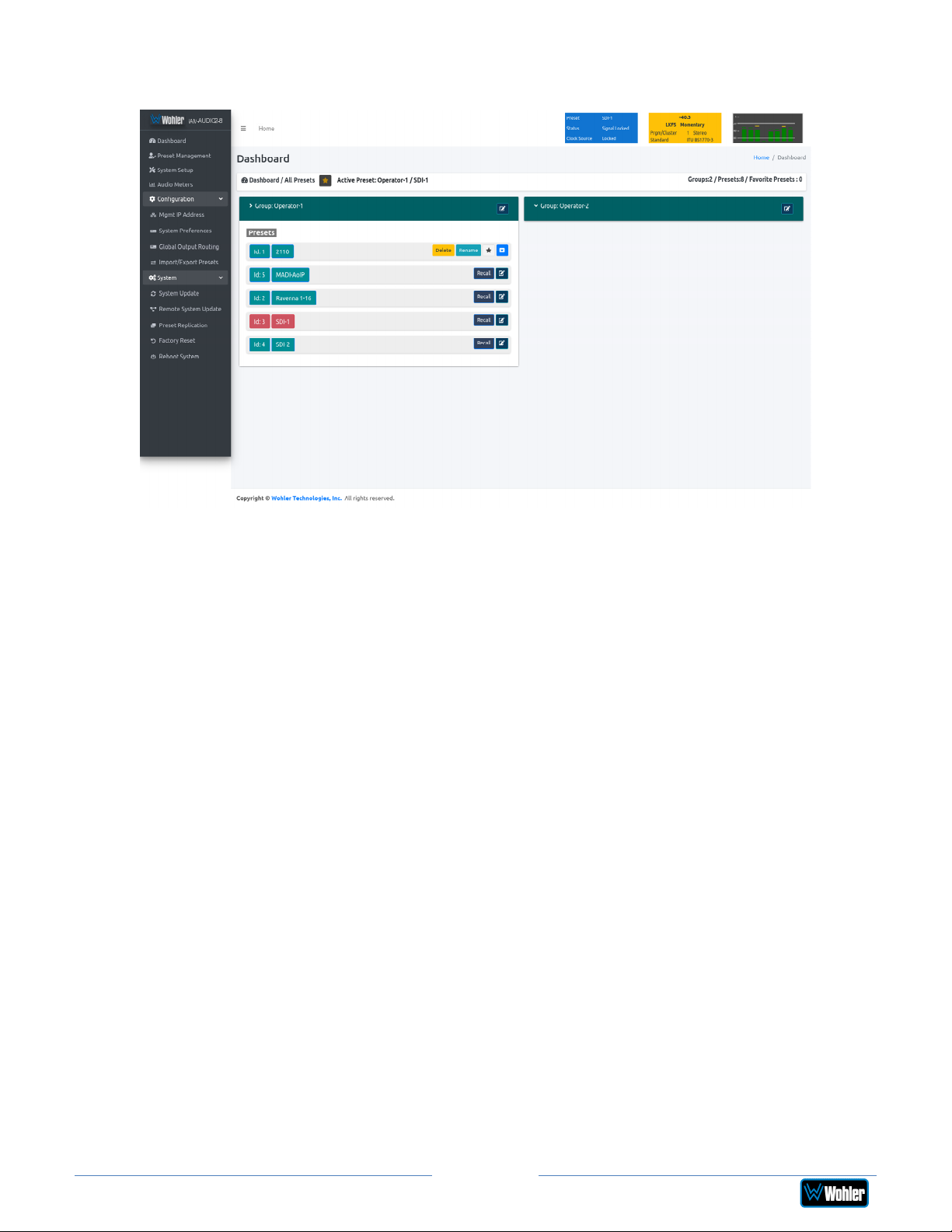
Figure 4–5: Dashboard Preset Edit
The Edit options for a Preset are:
1. Delete: Remove the Preset from the system. Do Not delete the currently
active Preset.
2. Rename: Rename the Preset, but keep all of its other characteristics.
3. Make Favorite: Make this Preset a favorite. This can be done for frequently
used Presets.
Page 57
iAM2-8
Page 58
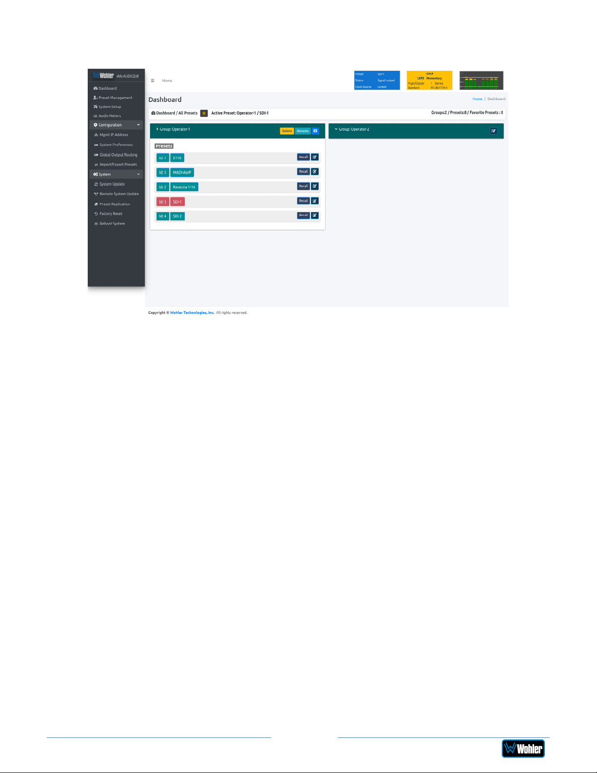
Figure 4–6: Dashboard Group Edit
The Edit options for a Group are as follows:
1. Delete: Delete the Group and all of the Presets it contains.
2. Rename: Rename the Group, but keep all of its other characteristics.
Page 58
iAM2-8
Page 59
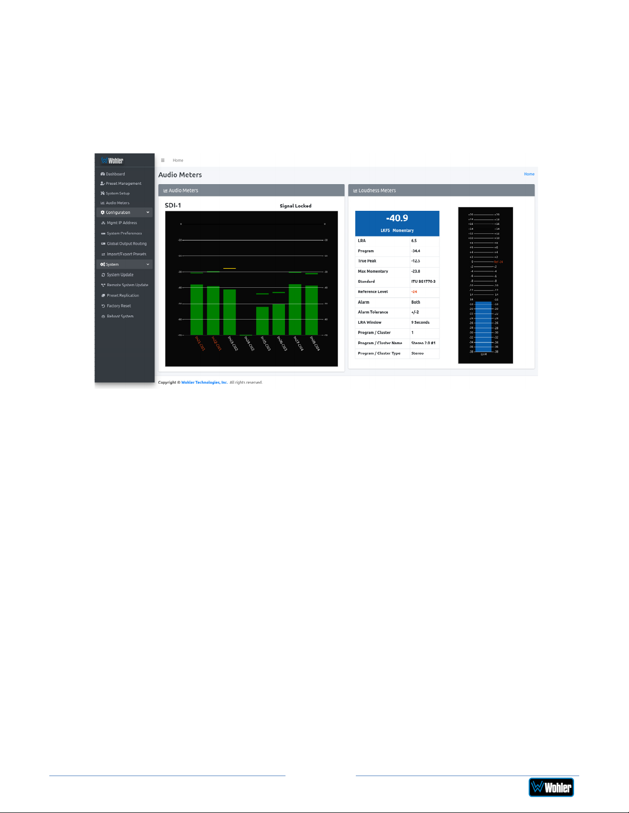
Audio Meters
Click on Audio Meters to remotely display the audio meters of the iAM2-8. This
display is shown in Figure 4-7. Also displayed is the name of the source that the
meters are displaying. In Figure 4-7, this is SDI/BNC-1.
iAM-AUDIO2-8
Figure 4–7: Audio Meters Display
Page 59
iAM2-8
Page 60
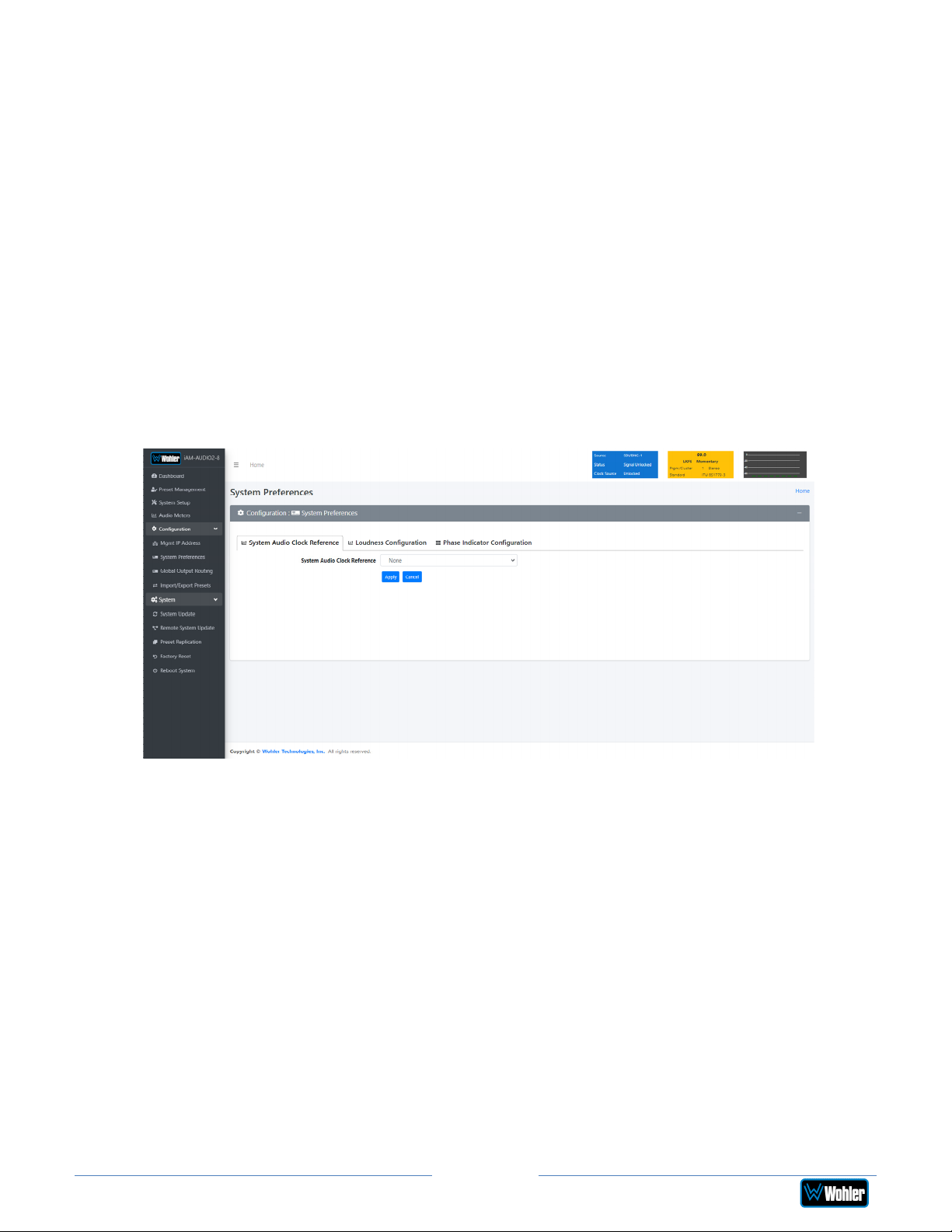
System Preferences
Click on System Preferences to find the System Audio Clock Reference, Loudness
Configuration, Phase Indicator Configuration, and Front panel Configuration tabs.
These are as shown in Figures 4-8, 4-9, 4-10, and 4-11.
System Audio Clock Reference
The System Audio Clock Reference setting provides a way to set the global clock
source for the unit. This setting will be used whenever a source is selected using
the Source Select knob or the Source Select Menu. If the System Audio Clock
Reference is set to None, then the currently selected source acts as the Clock
Reference. This tab is shown in Figure 4-8.
This System Audio Clock Reference setting can be overridden by the optional
System Clock Reference setting in the Preset Management menu when the Preset is
chosen.
Figure 4–8: System Audio Clock Reference Tab
iAM2-8
Page 60
Page 61
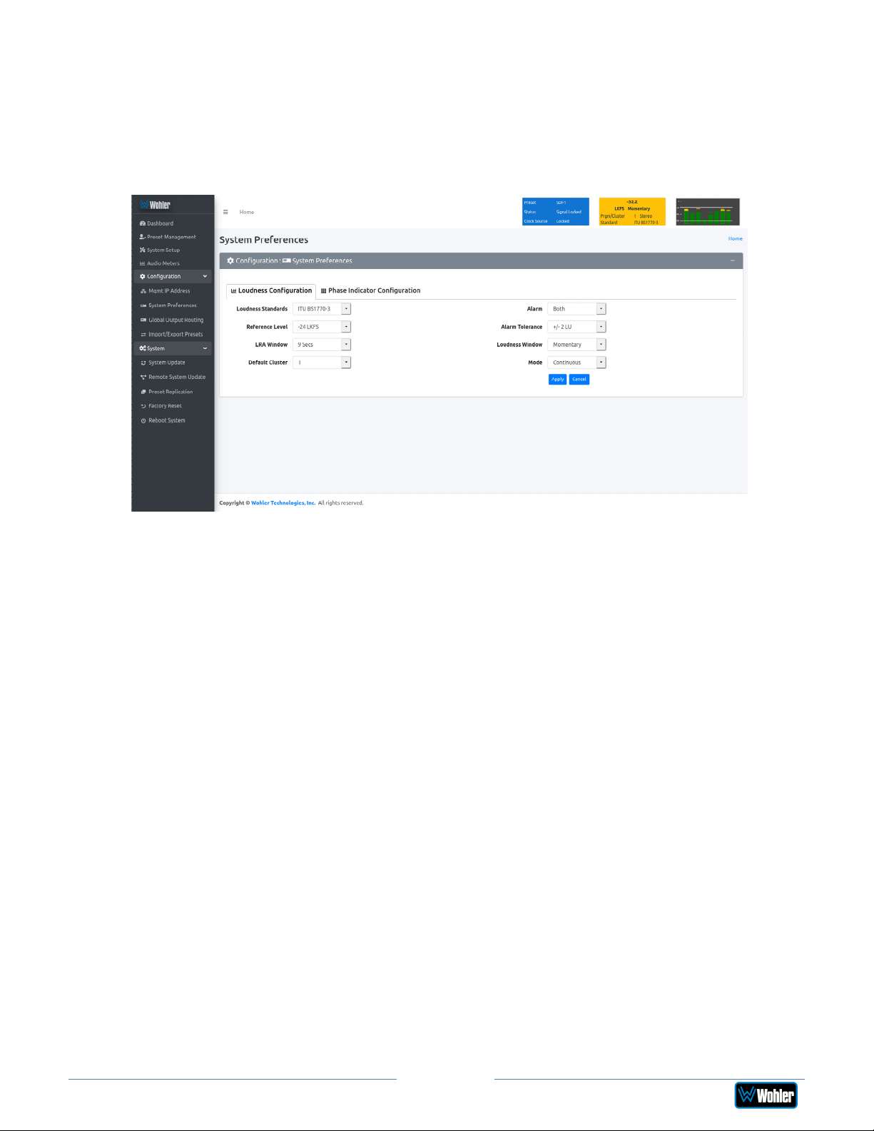
Loudness Configuration Tab
The Loudness Configuration tab allows you to make settings which will determine
how Loudness is to be calculated on the Loudness Meter. This tab is shown in
Figure 4-9.
Figure 4–9: Loudness Configuration Tab
iAM-AUDIO2-8
The following settings can be made on this tab:
1. Loudness Standard: This is the loudness standard by which the loudness
calculation is made.
2. Reference Level: This is the set point in the loudness measurement about
which the determination is made as to whether an alarm should be displayed.
3. LRA Window: This is a moving window of time over which the loudness
measurement is made.
4. Default Cluster: When a Metering Screen is entered, this is the number of
the cluster that will initially be monitored for Loudness.
5. Alarm:
a. Over: The Alarm indication will only appear when Loudness has
exceeded the Reference Level by the Tolerance amount.
b. Under: The Alarm indication will only appear when Loudness is below
the Reference Level by the Tolerance amount.
c. Both: The Alarm indication will only appear when Loudness has
exceeded or is below the Reference Level by the Tolerance amount.
d. Off: The Alarm indication will not appear.
6. Alarm Tolerance: This is the range over which a normal loudness indication
is given. Above or below this range will result in color changes in the graph.
7. Loudness Window: This may be set to Momentary, Short, or one of 22
values, ranging from one second to two hours.
8. Monitoring Mode:
Page 61
iAM2-8
Page 62
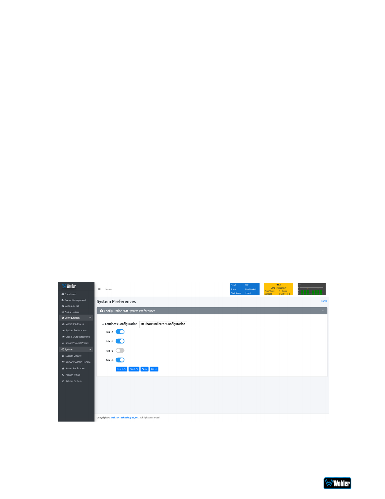
a. Manual: Touch the Manual button to enable Manual Mode. This allows
you to measure the loudness of a specific program or segment of a
program, such as a commercial. In this mode, the Start and Stop
button on the Loudness Meter screen can be manually used to begin
and end a loudness measurement interval. The reading for that
interval is then held on the Loudness Meter.
b. Continuous: Touch the Continuous button to enable Continuous
Mode. In this mode, loudness readings are continually made. The Stop
button on the Loudness Meter screen is not active.
Note: Further and more detailed descriptions of all of the above Loudness terms
may be found in the ITU-R BS.1770-3 loudness standard.
When you have finished making the settings click Apply to save them or click
Cancel to discard them.
Phase Indicator Configuration Tab
The Phase Indicator Configuration tab is as shown in Figure 4-10. It allows you to
select which channel pairs will receive a phase meter on the Metering Screen.
Generally, it is useful to monitor the relative phase of stereo pairs. However,
sometimes each channel of a pair is unrelated to each other. This can be because
the channels are used to convey two independent monophonic signals or that one
channel may be a Center channel and the other may be a Low Frequency Effects
channel. In these instances, the Phase Indicator would almost always indicate an
out of phase condition. Because this would be a needless distraction to the
operator, switches are provided on this tab to individually turn phase monitoring for
each channel pair on or off. Select All and Reset All buttons are also provided.
Figure 4–10: Phase Indicator Configuration Tab
iAM-AUDIO2-8
When you have finished making the settings click Apply to save them or click
Cancel to discard them.
iAM2-8
Page 62
Page 63
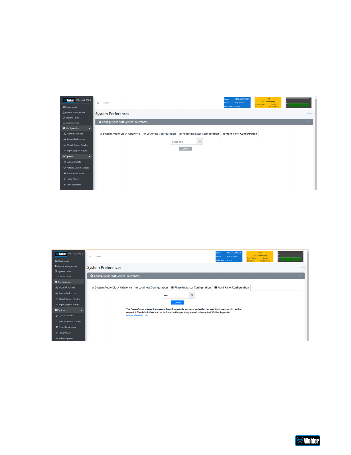
Front Panel Configuration Tab
To prevent accidental or unauthorized changing of critical settings in the local
product menus, it is possible to restrict access. The Front Panel Configuration Tab
entry screen is shown in Figure 4-11. This provides an entryway to the Front Panel
Configuration Tab shown in Figure 4-13. To proceed, you must enter the correct
Passcode. If no Passcode has been set, the default Passcode is 0-0-0-0.
Figure 4-11: Front Panel Configuration Tab – Passcode Entry
If an incorrect Passcode is entered, the screen shown in Figure 4-12 appears. Click
the Continue button to try again. If you have forgotten the Passcode, this can be
remedied by performing a Factory Reset. Unfortunately, this will also erase all of
the menu settings. You may also contact Wohler Technical Service for help.
Figure 4-12: Unrecognized Passcode
When you have successfully entered the Passcode, the Passcode Settings screen
will appear, as shown in Figure 4-13.
Page 63
iAM2-8
Page 64
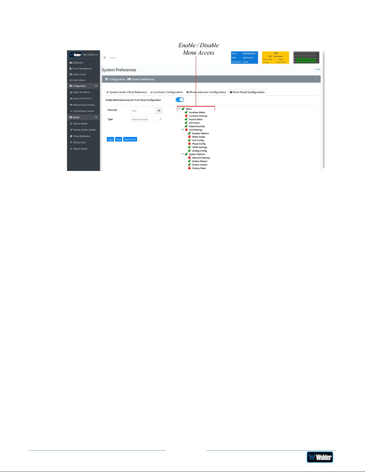
Figure 4-13: Front Panel Configuration Tab
The functions on this screen are as follows:
Enable Restricted Access for Front Panel Configuration: This switch will turn
ON or OFF protection or blocking of any local product menus, except for the
Passcode Settings menu, which is always Passcode protected.
Passcode: You may enter a new Passcode in this field. The Passcode can be any 4digit number. Be sure to save the Passcode in a safe place for future reference.
Type: Select the type of disabled button appearance on the local product menus
using the Type button. The choices are:
Passcode Access: The Passcode protected function buttons include a small
orange padlock icon within the buttons. This is shown in the left image of
Figure 4-14. These buttons can only be accessed using the correct Passcode.
No Access: If the function buttons are protected by No Access, the buttons
are grayed out and non-functional, as shown in the right side of Figure 4-14.
These buttons cannot be accessed.
Apply Default: Clicking this button returns the settings in this screen to the
factory default values. The Passcode becomes 0-0-0-0.
Reset: Clicking this button undoes any settings you have made on this tab.
Enable / Disable Menu Access: This section provides a nested chart of the local
menus that exist in the product. You may set which menus are affected by
restrictions. Click any menu shown to change it between affected (red icon) and
unaffected (green icon).
Apply: When you have completed the desired settings in this tab, click Apply to
put them into effect.
Page 64
iAM2-8
Page 65
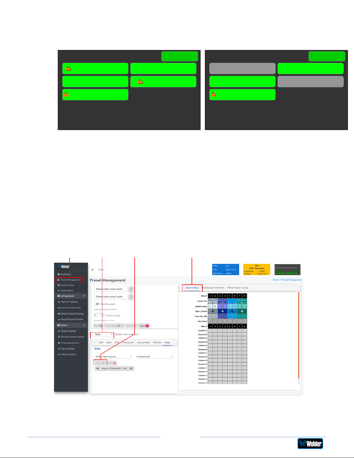
Figure 4-14: Examples of Local Menu Protection
Passcode Access: No Access:
System Options
Menu
System Options
Menu
Network Settings System Reboot
System Update
Passcode Settings
Factory Reset
Preset Management
Presets are monitoring configurations that can be composed of channels from
multiple sources and displayed on the meters in any order. Presets should be set up
to allow operators to quickly shift between setups for monitoring. The Preset
Management screen contains selections of all of the details for a Preset, and is
largely arranged in a matrix format connecting input channels to monitoring
channels. The screen is shown in Figure 4-15.
Figure 4–15: Configure Presets
Network Settings System Reboot
System Update
Passcode Settings
Factory Reset
Preset
Management
iAM-AUDIO2-8
Clock
Selection
Autofill
Selection
Preset Input/Output Matrix:
Preset Input Routing
1. Preset Configuration: You may create a new Preset, adjust an existing
Preset, or create a new Preset from an existing Preset:
Page 65
iAM2-8
Page 66

• To create a new Preset, enter the name for the new Preset in the
field to the left of the word Preset. Then make all of the settings
needed and save it.
• To make changes to an existing Preset, select it from the pull
down list, make the needed changes and save it.
• To create a new Preset starting with an existing Preset, first
select the existing Preset from the pull down list. Next, enter the name
for the new Preset and save it. Then make the needed changes and
save it.
Presets may be created for any licensed inputs, even if the SFP module for an
input is not plugged into its respective socket at the time. This makes it easy
to swap SFP input modules without having to recreate presets after the
insertion or removal of an SFP module. Note that if a licensed SFP module is
not detected, such as when one is removed to be swapped, its monitoring
inputs will be muted. Likewise, if the required license has not been entered
for an SFP module that is inserted, its monitoring inputs will also be muted.
Refer to the Licenses section in this chapter to install software licenses.
2. System Clock Reference: There must be a system clock reference for
monitoring to take place. Select a reference from the pull down list. The best
choice is a stable, always present clock source locked to house sync. Second
to that, use the selected input as the clock. Generally speaking, Internal is
not the best choice.
3. Speaker Delay: If desired, an audio delay may be inserted ahead of the
monitor speakers. This delay may range from 0 to 170 mS. Typically, delay is
used to align the monitored audio with a video monitored signal.
4. Input Selection: Audio from any of the input sources may be applied to the
monitoring scheme in any way. For example, you may have 6 channels from
an SDI stream, along with 2 AES channels, and along with 2 analog channels
assigned your choice of meters. A Preset Input/Output Matrix is provided
on the lower right side of the screen to allow you to assign each channel.
Simply select each input source, one at a time, and then check the boxes in
the Matrix to apply each input channel number to a metered channel
number. They do not have to be applied in any specific order. The order of
assignment should be chosen to make it easy for the operator to understand.
If there are more than 8 channels in a source, the desired group of 8 can
also be selected from the box in the lower left of the screen.
5. Autofill Selection: If you simply want to map all 8 input channels to all 8
meters in the same order, click the Autofill button. The Preset
Input/Output Matrix will automatically fill out. To remove all mapping,
click the Reset button that is adjacent to the Autofill button.
6. Cluster Definition and Naming: Channel Clusters are a series of channels
that are all associated with monitoring the same signal. For example, a
Stereo Cluster consists of two channels that together monitor a stereo signal.
A Surround 5.1 Cluster consists of 6 channels that together monitor a 5.1
surround sound signal. Clicking a Cluster Info box opens a Cluster
selection box.
In the Cluster box, you can select the type of Cluster from a pull down
selection. The available Cluster Type selections are:
Page 66
iAM2-8
Page 67

• Mono 1.0: The channel will appear within a single-channel cluster.
• Stereo 2.0: The channels will appear within a two-channel cluster.
• Surround 5.1: The channels will appear within a 6-channel cluster.
• Surround 7.1: The channels will appear within an 8-channel cluster.
• Custom: You may define a 0 to 8 channel cluster.
Multichannel clusters will expand to the right and overwrite any clusters on
overlapping meter positions.
By default, all odd numbered channels will map to the left speakers and all
even numbered channels will map to the right speakers. You may change this
using the crosspoint selections in the Input/Output Matrix.
A default name will be chosen and it will appear on the metering screen. You
may name the Cluster anything you want by simply changing the words
within the Cluster Name field.
When finished, click Update. To undo your change, click Reset. To undo all
of the Cluster changes for the 8 channels, click Reset All.
7. Speaker Assign: Speaker assignments are made automatically when a
cluster is set. However, it can be that in an actual signal, the channel
assignments may be different than what the automatic assignment assumes.
A speaker assignment adjustment is provided for each channel, should you
need to override the automatic settings. It is important to accurately assign
the function of each channel so that the Loudness calculations will be
accurate. Clicking a Speaker Assign button on a channel opens a box that
lets you change the current setting.
8. Mute/Unmute: A Mute/Unmute control is provided for each channel,
although the adjustment will affect all channels in the Cluster. This allows the
operator to just see the meters for certain channels and not hear the audio.
This is an alternate action control.
9. The Global Phase Indicators tab is as shown in Figure 4-16. It allows you
to select which channel pairs will receive a phase meter on the Metering
Screen in this Preset. Generally, it is useful to monitor the relative phase of
stereo pairs. However, sometimes each channel of a pair is unrelated to
each other. This can be because the channels are used to convey two
independent monophonic signals or that one channel may be a Center
channel and the other may be a Low Frequency Effects channel. In these
instances, the Phase Indicator would almost always indicate an out of phase
condition. Because this would be a needless distraction to the operator,
switches are provided on this tab to individually turn phase monitoring for
each channel pair on or off. By default, the settings for a Preset are the same
as the system-wide configuration set on the System Preference tab.
However, to make unique settings for this Preset, uncheck Apply Global
Phase Indicator Settings and then simply click each switch to the desired
on or off position. Select All and Reset All buttons are also provided.
Page 67
iAM2-8
Page 68
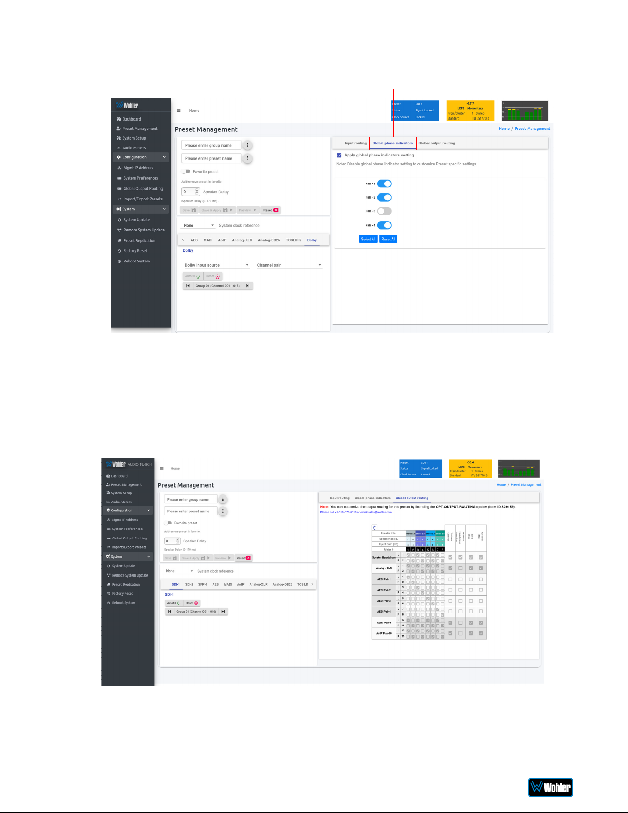
Figure 4–16: Global Phase Indicator Enable / Disable
Global Phase Indicators
iAM-AUDIO2-8
10. The Output Routing tab is shown in Figure 4-17 when the OPT-OUTPUTROUTING capability was not purchased and licensed. This tab shows how
signals from the inputs are routed to the outputs. It allows you to view, but
not change this default routing.
Figure 4-17: Default Output Routing
However, if the OPT-OUTPUT-ROUTING license is installed, this tab allows
you to determine exactly which input channels are routed to which outputs.
It then appears as shown in Figure 4-18. This very flexible capability allows
you to route signals according to Preset or as a default for the whole system.
Page 68
iAM2-8
Page 69
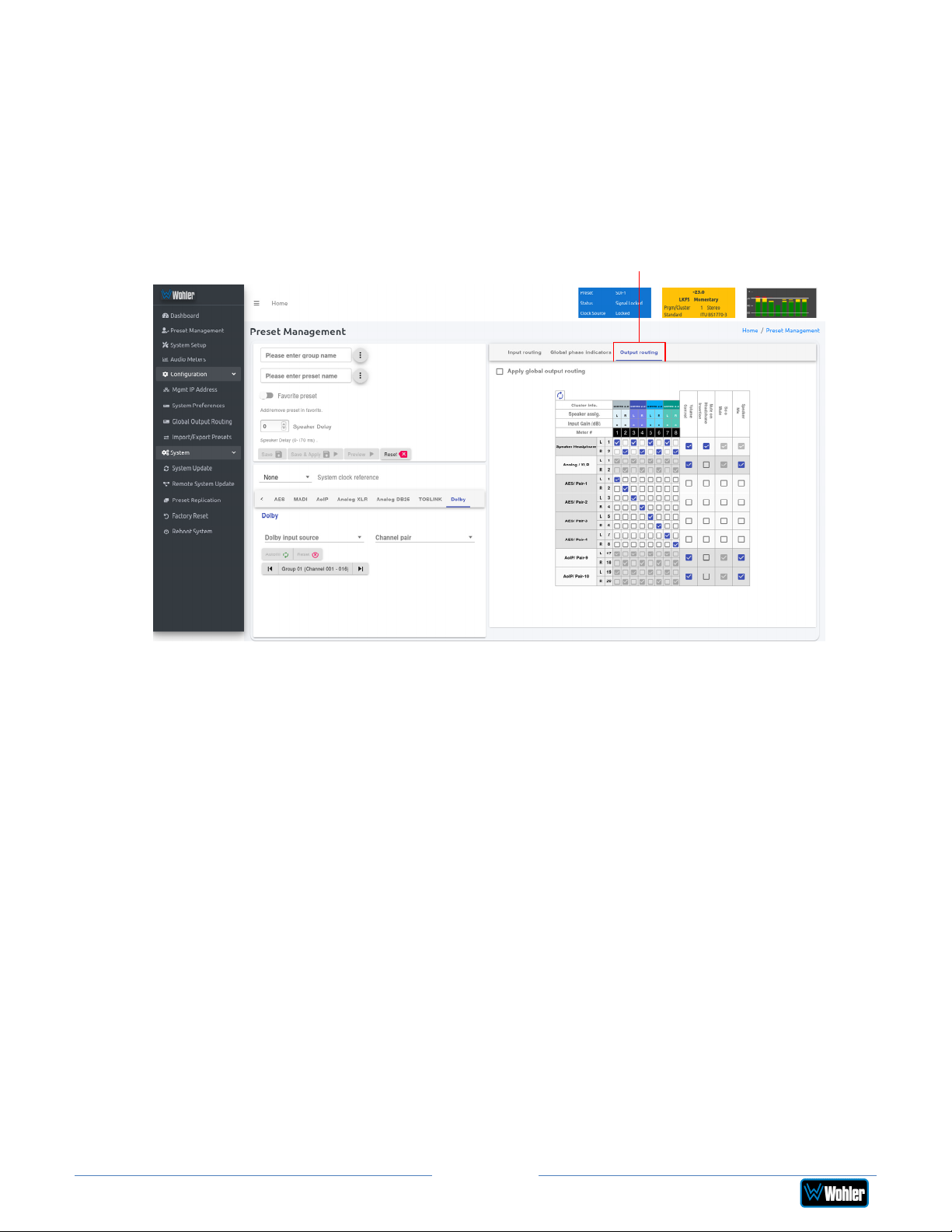
Refer to the Global Output Routing section in this chapter to learn the
function of each of the checkboxes and of the matrix in this tab.
To set up a different input to output routing scheme for the Preset you are
creating, click the Global Output Routing tab and uncheck the Apply
Global Output Routing checkbox. You may then adjust the output routing
as you desire on this tab and it will only apply to this Preset.
Figure 4-18: Output Routing Preset Tab
Output Routing
iAM-AUDIO2-8
11. When you have finished creating a Preset or making changes to a Preset,
either click the Save button to save the Preset, click the Save & Apply
button to save the Preset and make it the current Preset, or click the Reset
button to discard the changes just made. These selections are shown in
Figure 4-18.
Page 69
iAM2-8
Page 70
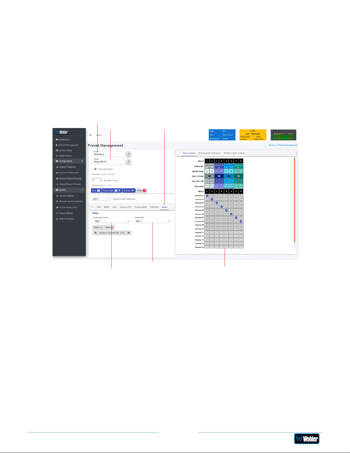
Dolby Presets
Dolby Presets are useful for customers who want to simultaneously monitor both
Dolby decoded channels and other inputs or want to have an auto-zoom to monitor
a certain pair that is known to be carrying Dolby encoded audio.
Creating a Dolby Preset is in many ways very similar to creating any other Preset.
Refer to the Preset Input Routing section of this chapter. Figure 4-19 shows a
Dolby Preset being created.
Group Name
iAM-AUDIO2-8
Preset Name Dolby Source
Figure 4-19: Creating a Dolby Preset
Channel Pair
Dolby Source List
Preset Input/Output Matrix
After clicking Preset Management in the list on the left, and selecting or creating
a Group name and Preset name, as shown in Figure 4-19, use the following steps to
set up a Dolby Preset:
1. Click the Dolby Input Source, as indicated in Figure 4-19. A list of all of
your physical inputs will display. Select the one containing the Dolby signal
that you are interested in monitoring.
2. Click the Channel Pair. A list of all of the channel pairs in your selected
source appears. Select the one that contains the Dolby signal to be
monitored.
3. Using the Preset Input/Output Matrix, select which decoded Dolby
channels should appear on which meters. To automatically fill out this matrix,
mapping channels 1 - 8 to meters 1 - 8, simply click the Autofill button.
Note that by default, channels 9 and 10 are a downmix of the decoded Dolby
channels and can be mapped to any of the metering channels.
When you have finished making all of the settings for this Dolby Preset, click Save
& Apply.
iAM2-8
Page 70
Page 71
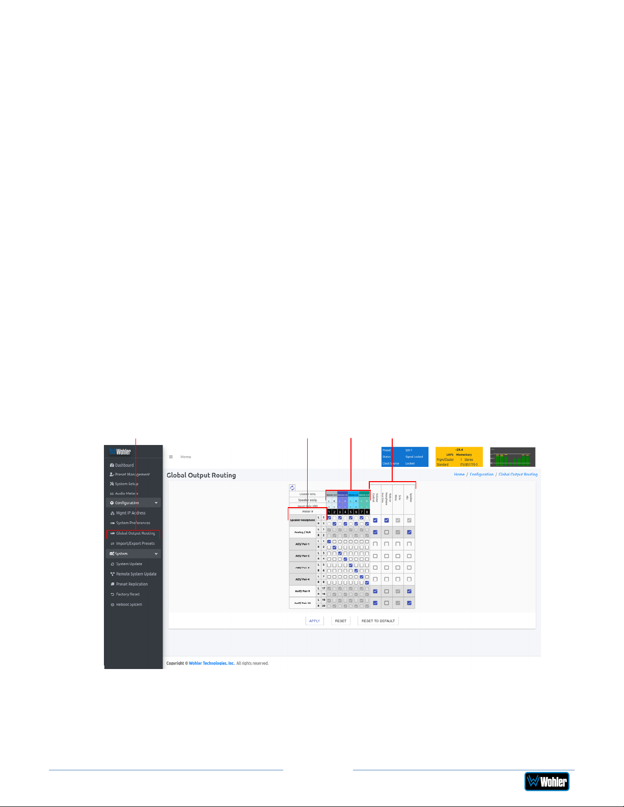
Output Routing
The Output Routing licensed feature (OPT-OUTPUT-ROUTING) allows channels to
be routed or combined and routed in custom ways to various destination outputs.
Output Routing is applied to:
1. Signals monitored using "Input Source select" from the Front Panel,
2. Presets that have been created to apply the Output Routing.
Any change to the routing will affect the Presets that have "Apply Output Routing"
selected. For example, multiple channels of a 7.1 channel program can be
combined and directed to the left or right internal speakers. Six or eight channels
could be directed to the AES outputs, which could feed an external surround sound
system. Contact Wohler Sales to purchase the license for the OPT-OUTPUTROUTING feature.
If Output Routing is not licensed, then any of the inputs can be monitored in
stereo or mono only through the internal speakers. The headphone jack, the analog
XLR outputs, and the first AES output will follow whatever is directed to the
speakers.
When licensed, select Global Output Routing under Configuration. This will
display the Global Output Routing screen. This screen contains a matrix of
checkboxes which are an easy way for you to set up the wide variety of input to
output routing and mixing capabilities. The Global Output Routing screen is
shown in Figure 4-20.
Global Output
Routing
iAM-AUDIO2-8
Figure 4-20: Global Output Routing Option
Destination
Outputs
Source
Inputs
Output
Options
Page 71
iAM2-8
Page 72

Destination Outputs
On the left of the Global Output Routing screen are listed the Destination
Outputs. These are the outputs to which any input can be routed. They are as
follows:
1. Speaker/Headphone: Selected inputs will be sent to the left and right
speakers. The default routing is set as per the Speaker Assignment, left
channels are sent to the left speaker and right channels are sent to Right
speaker.
2. Analog XLR: Selected inputs will be mixed to the left and right channels and
played through the two Analog XLR Outputs.
3. AES/Pair-1: Selected inputs will be mixed to the left and right channels and
played through the AES Pair 1 Output.
4. AES/Pair-2: Selected inputs will be mixed to the left and right channels and
played through the AES Pair 2 Output.
5. AES/Pair-3: Selected inputs will be mixed to the left and right channels and
played through the AES Pair 3 Output.
6. AES/Pair-4: Selected inputs will be mixed to the left and right channels and
played through the AES Pair 4 Output. The four AES outputs can be used
together to output, for example, 5.1 or 7.1 surround channels to an external
surround sound monitor system.
7. AoIP/Pair-9 (DANTE / RAVENNA): Selected inputs will be mixed to AoIP
transmit channels 17 and 18. Note that configuration for channels 1 - 16 is
not supported. Use a Dante Controller or Anneman/Zman web interface to
route these channels appropriately.
8. AoIP/Pair-10 (DANTE / RAVENNA): Selected inputs will be mixed to
Channel 19 and Channel 20. Use a Dante Controller or Anneman/Zman web
interface to route the remaining pairs appropriately.
Source Inputs
The source inputs which may be routed are described in this section.
1. Cluster Information: Cluster information show type of cluster and cluster
name.
2. Speaker Assignment: Speaker assignment can be used to configure to
which speakers the audio is routed to. The possible options are:
L Left
R Right
C Center
LFE Low Frequency Effects
Ls Left Surround
Rs Right Surround
Bsl Back Surround Left
Bsr Back Surround Right
Page 72
iAM2-8
Page 73

S Mono Surround
3. Input/Output Matrix: By checking the various boxes in this matrix, any
input channels can be freely routed to any output channels. This flexible
channel assignment is called a Free Mix. However, when the Speaker Mix
box is checked in the Output Options section, the associated row within the
matrix is automatically set to the speaker mix and the checkboxes are
grayed out indicating that you may not change them with a Free Mix
assignment.
Output Options
The optional settings in this section allow for customization.
1. Speaker Mix: This option selects whether an output has the Speaker Mix
or a Free Mix as set in the Routing Input section. The Speaker/Headphone
output is always in the Speaker Mix.
2. Solo/Mute: This setting determines whether or not the outputs are affected
by solos and mutes. The Speaker/Headphone output is always affected by
solos and mutes. Note also, that all outputs in Speaker Mix mode also are
affected by solos and mutes.
3. Mute on Headphone Insertion: This option controls whether the outputs
should be muted upon a headphone insertion. This setting can be adjusted
even for outputs whether they are in Speaker Mix or Free Mix modes.
4. Volume Control: This setting determines whether each output pair is
adjusted by the Volume Control knob. Speaker/Headphone outputs are
always affected by the volume control knob, as are any outputs that are in
Speaker Mix mode.
Typical Questions Regarding Output Routing
The questions and thoughts in this section are commonly asked by people when
setting up the licensed Output Routing capability.
What signal outputs can be controlled using the Output Routing
feature?
All the outputs on the iAM2-8 can be controlled using the Output Routing feature.
This includes – Internal Speakers, Analog XLR outputs, all 4 pairs of AES outputs on
HD-15, and AoIP Pair 9 and Pair 10.
How do the outputs behave if I do not purchase OPT-OUTPUTROUTING license?
If Output routing license is not purchased, the outputs are configured as follows:
1. Speakers: All monitored channels are always available on the internal
speakers. The left and right speaker assignment is determined by the
Speaker Assignment. Audio on the speakers is controlled by the Volume
iAM2-8
Page 73
Page 74
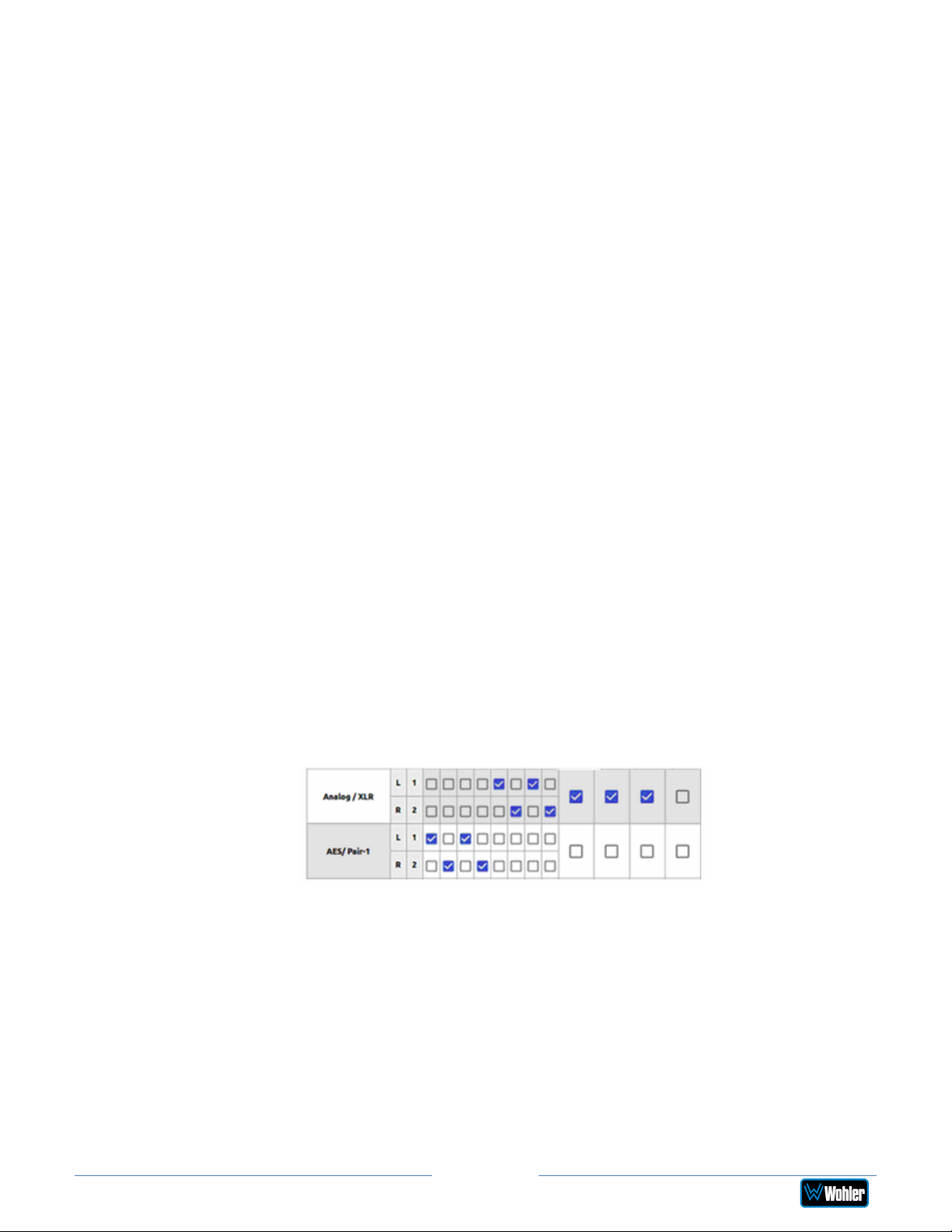
and Balance knobs and is muted whenever a headphone is inserted into the
Headphone jack.
2. Analog XLRs: These outputs follow the same configuration as the internal
speakers. They are controlled by the Volume and Balance knobs and are
muted whenever a headphone is inserted into the Headphone jack. These
outputs also follow the solo/mute selections on the Audio Meter screen.
3. AES Pairs 1 through 4: The first 8 channels appear on these outputs in
numeric order. They are pre-fade, so they are unaffected by the Volume and
Balance knobs or headphone insertion. They are also unaffected by the
solo/mute selections on the Audio Meter screen.
4. AoIP Pairs 9 and 10: These outputs follow the same configuration as the
internal speakers. They are controlled by the Volume and Balance knobs
and are muted whenever a headphone is inserted into the Headphone jack.
These outputs also follow the solo/mute selections on the Audio Meter
screen.
What is the difference between Global Output Routing and Output
Routing in Presets?
Both are used to configure the unit outputs. Global Output Routing is applied by
default when you select a source or when creating presets and when you don’t
change the Output Routing unique to any Preset. Changes to either of these are
disabled if the OPT-OUTPUT-ROUTING license is not purchased.
How do I route whatever is being monitored to the XLR and AES
outputs?
Using Global Output Routing (optional licensing upgrade), you may route any
signals to the XLR & AES outputs. You may route signals to the XLR outputs using
the Analog/XLR checkboxes and route signals to the AES outputs by using the
AES/Pair 1 to Pair 4 checkboxes.
As shown in the above example, signals appearing on Audio Meter channels 1
through 4 are routed to AES Pair 1 and signals from Audio Meter channels 3 to 8
are routed to the Analog XLR outputs.
How do I have a downmixed pre-fade output on AES Pair-1
combined with a post-fade output on the Analog XLRs?
To downmix a pre-fade output on AES Pair-1, uncheck the Volume Control
checkbox for that AES pair. For a Post-fade output on the Analog XLRs, check
Volume Control checkbox.
Page 74
iAM2-8
Page 75
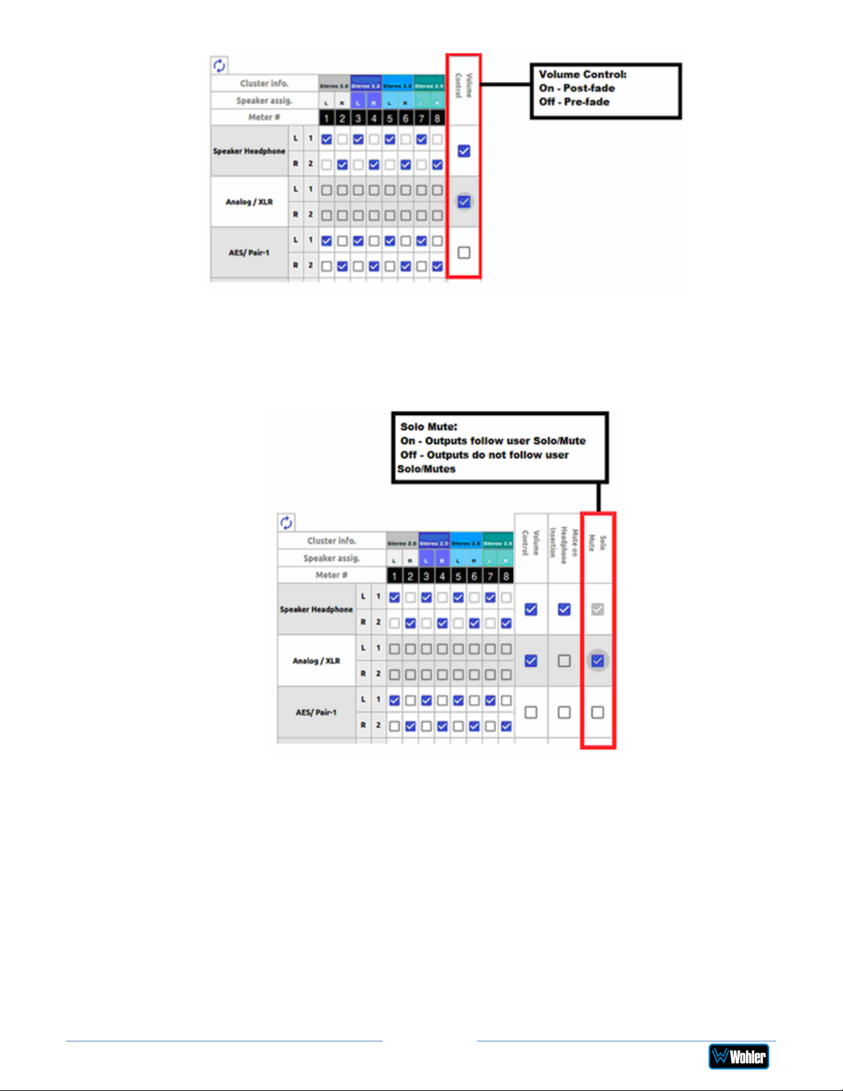
How do I make the XLR outputs follow the Audio Meter screen
solos & mutes while the AES Pair-1 does not?
Make the settings shown in the Solo / Mute column:
The setting shown above determines that outputs will follow the Audio Meter screen
solos & mutes for the XLR outputs because the checkbox is checked. It is not
checked for the AES outputs, so they will not be affected by the solo & mute
choices. This feature requires the optional OPT-OUTPUT-ROUTING output routing
license.
Page 75
iAM2-8
Page 76
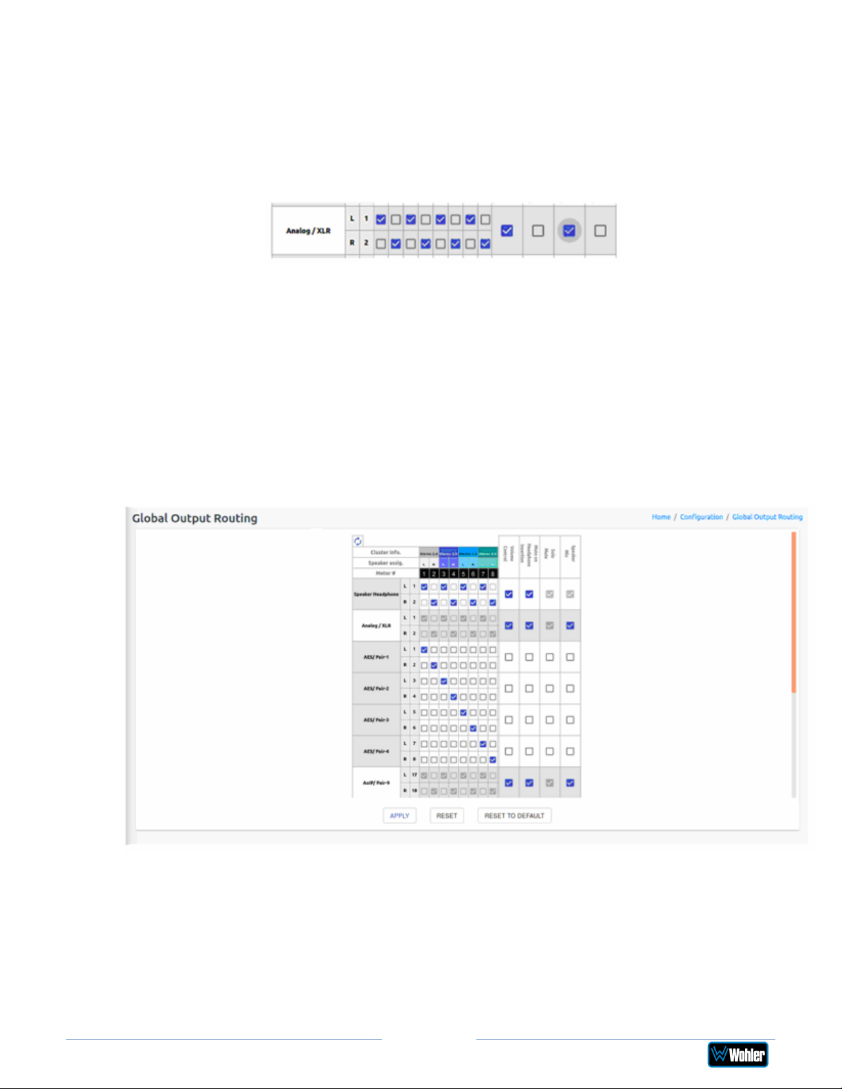
How do I route only specific monitored channels to the Analog
XLR outputs?
When the optional OPT-OUTPUT-ROUTING license is purchased, you may route
specific channels as shown below. Here Audio Meter channels 1, 3, 5, and 7 are
routed to the left analog XLR output and Audio Meter channels 2, 4, 6, and 8 are
routed to the right analog XLR output. Unchecked channels are not routed. Make
sure the Speaker Mix selection is turned off to enable this selection.
The optional Global Output Routing feature works great. But what
if we don't want to create any Presets and want to monitor audio
only using Source Select? How would I configure different outputs
for Source Select choices?
Use the Global Output Routing settings to determine how the outputs are
configured for source select options.
The Global Output Routing feature allows channels to be routed or combined and
routed to various destinations. For example, channels 1 to 8 can be routed to AES
outputs:
How do I keep the internal speakers muted and have audio only
on the analog XLR outputs?
When the optional OPT-OUTPUT-ROUTING license is purchased, in the Global
Output Routing configuration, do not select any Speaker Headphone
checkboxes for any meter channels as shown below, and then select the desired
meters for Analog XLR. In this way, the internal speakers will always be muted, but
iAM2-8
Page 76
Page 77
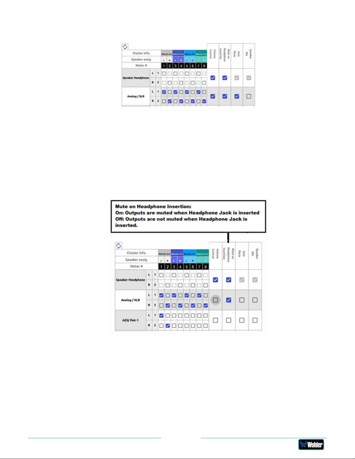
the audio will appear on the Analog XLR outputs (for amplified external speakers).
Make sure that the Speaker Mix checkbox selection is unchecked for Analog/XLR.
How do I ensure that the outputs are automatically muted when
the Headphone jack is inserted?
When the optional OPT-OUTPUT-ROUTING license is purchased, in the Global
Output Routing configuration, if the Mute on Headphone Insertion checkbox is
ON then the outputs get automatically muted when a headphone is inserted into
the Headphone jack.
As shown below, if a headphone is inserted then the output on the Analog XLRs will
be muted, while the audio on AES Pair 1 will remain on.
What are AoIP-Pair 9 and AoIP Pair 10?
AoIP-Pair 9: Selected inputs will be mixed to AoIP transmit channels 17 and 18.
Note that configuration for channels 1 - 8 is not supported. Use a Dante Controller
or Zman web interface to route these channels appropriately.
AoIP-Pair 10: Selected inputs will be mixed to Channel 19 and Channel 20. Again,
use a Dante Controller or Zman web interface to route the remaining pairs
appropriately.
iAM2-8
Page 77
Page 78
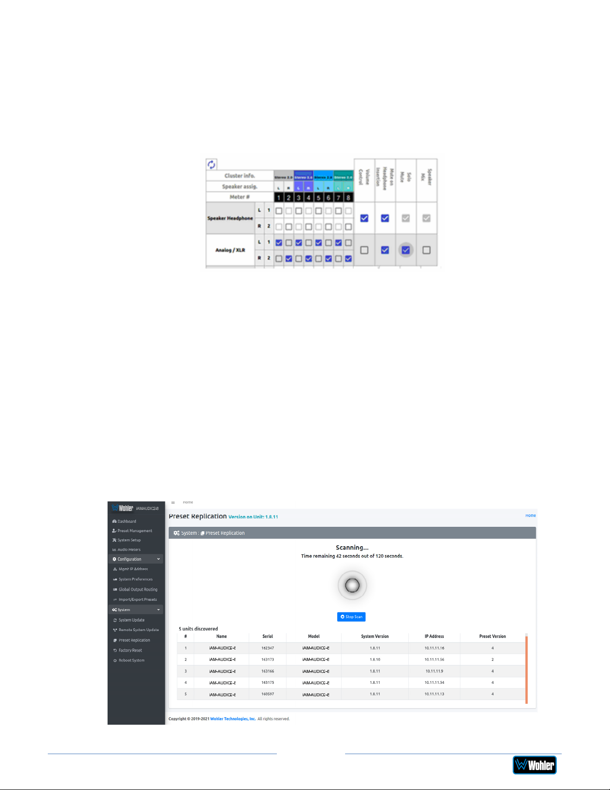
How do I ensure that my outputs are pre-faded but follow the
solo-mutes on the web interface? This will allow us to monitor
only the unmuted/solo Audio Meter channels on amplified stereo
speakers connected to the Analog XLR’s.
In the Output Routing setting, for the Analog XLR outputs, keep the Volume
Control checkbox unchecked and the Solo/Mute checkbox checked. This ensures
that the Volume Control is not applied to the outputs, while the Solos/Mutes are.
Preset Replication
Preset Replication allows you to copy presets from a master unit to multiple iAM2-8
units. This can save a lot of setup time if multiple units all need basically the same
setup.
To start Preset Replication, click on the Preset Replication tab on the master unit.
This will start the unit discovery process and will list all the iAM2-8 units that you
currently have on your network. The discovery process will continue for a period of
2 minutes. However, you may stop the discovery process sooner if you believe all
the units in the network have been discovered. Simply click the Stop Scan button.
Figure 4-21: Preset Replication Scanning Screen
Page 78
iAM2-8
Page 79
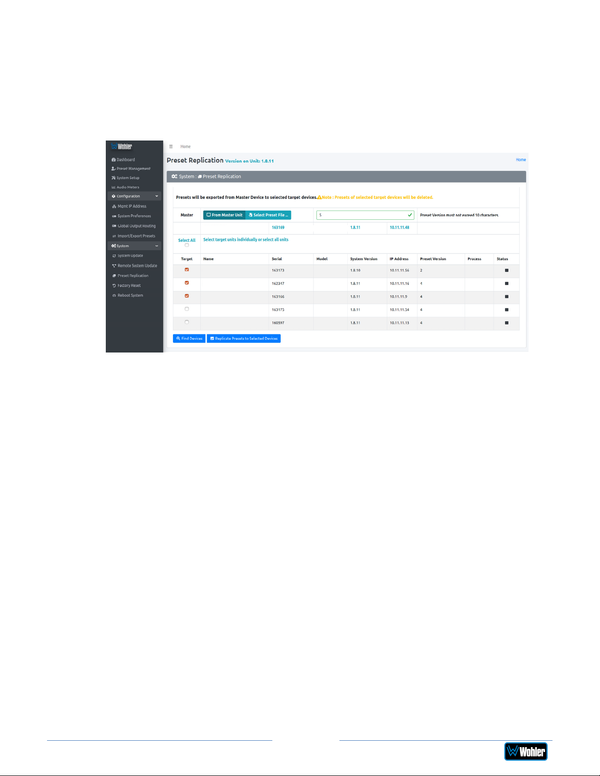
Once all the units are discovered you may either copy the presets that are currently
created on the Master unit or can use an external preset file that you want to copy
to any or all of the Target units. Note that any and all of the Presets that may
already be contained in each Target unit will be erased by copying the new
Presets.
Figure 4-22: Preset Replication Target Selection Screen
iAM-AUDIO2-8
iVAM
iAM-AUDIO2-8 iAM-AUDIO2-8
iAM-AUDIO2-8
iAM-AUDIO2-8
iAM-AUDIO2-8
iAM-AUDIO2-8
iAM-AUDIO2-8
iVAM
iAM-AUDIO2-8
iAM-AUDIO2-8
iAM-AUDIO2-8
iAM-AUDIO2-8
iAM-AUDIO2-8
Click either From Master Unit or Select Preset File. This determines the source
of the Presets to be copied. Preset Files would be files that you have previously
stored in the computer running the Web GUI.
You may add a descriptive name or version to the Presets being copied. This may
aid in remembering what tag or version of the presets are available on the unit. The
Preset name or version may be up to 10 characters in length.
Next, select the Target units from the list of units shown by checking or unchecking
each of the Target boxes at the left. Alternatively, you may click Select All to
select all of the units. Then select the Replicate Presets to Selected Devices
button. The progress of the Preset replication for each unit, as the Presets are being
copied, will be displayed in the Process column. When all of the Presets have been
copied to each of the selected units, you may leave this screen.
Page 79
iAM2-8
Page 80
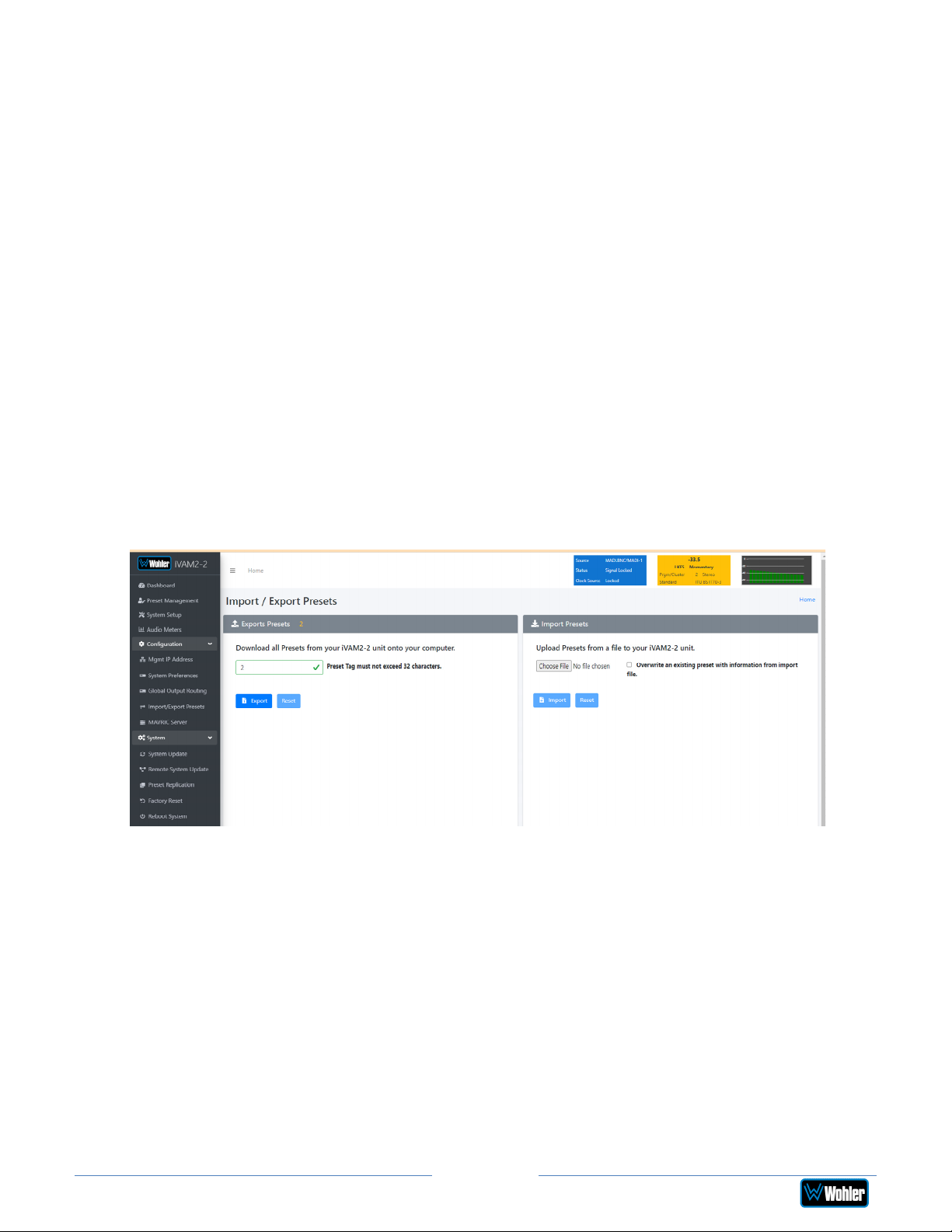
Import/Export Presets
Use the Import / Export Presets page to manage the Preset database in the
iAM2-8. You may export the Preset database onto the computer hard drive for
security backup purposes or as a means to transfer it to another iAM2-8. Likewise,
it can be used to import a Preset database from the computer hard drive into the
iAM2-8. In this way, a Preset configuration may be only devised once and then
duplicated into all of the iAM2-8 units in a system, saving significant effort.
The iAM2-8 will create Preset Tags for the each set of Presets. Refer to Figure 4-
23. You may also change these Preset Tags, using the Preset Change Field. They
allow you to quickly resolve questions about which Presets on various units are the
most up to date. They will also allow you to determine whether Presets have been
modified. If the Preset Tag displayed contains the suffix "-dirty" then at least one
Preset has been changed in some way.
While exporting the file, the Preset Tag is appended to the filename, this allows you
to store multiple Preset files with different file name. For example, if the Preset Tag
is v1.0.0 then for iAM2-8 the default filename would be "wohler_presets_iAM2-8v1.0.0.pdb" Do not change the file suffix and prefix (marked in red). However, you
may change the Preset Tag to any number or text to suit your requirements.
Figure 4–23: Database Export
Export Configuration
Use the following steps to save the Preset configuration in the iAM2-8 to the
computer hard drive:
1. If you need to, revise the Preset Tag name, observing the advice in the
advice in the previous section.
2. Click the Export button on the Import / Export Presets page, as shown in
Figure 4-24.
3. A small Verify window will appear:
Page 80
iAM2-8
Page 81
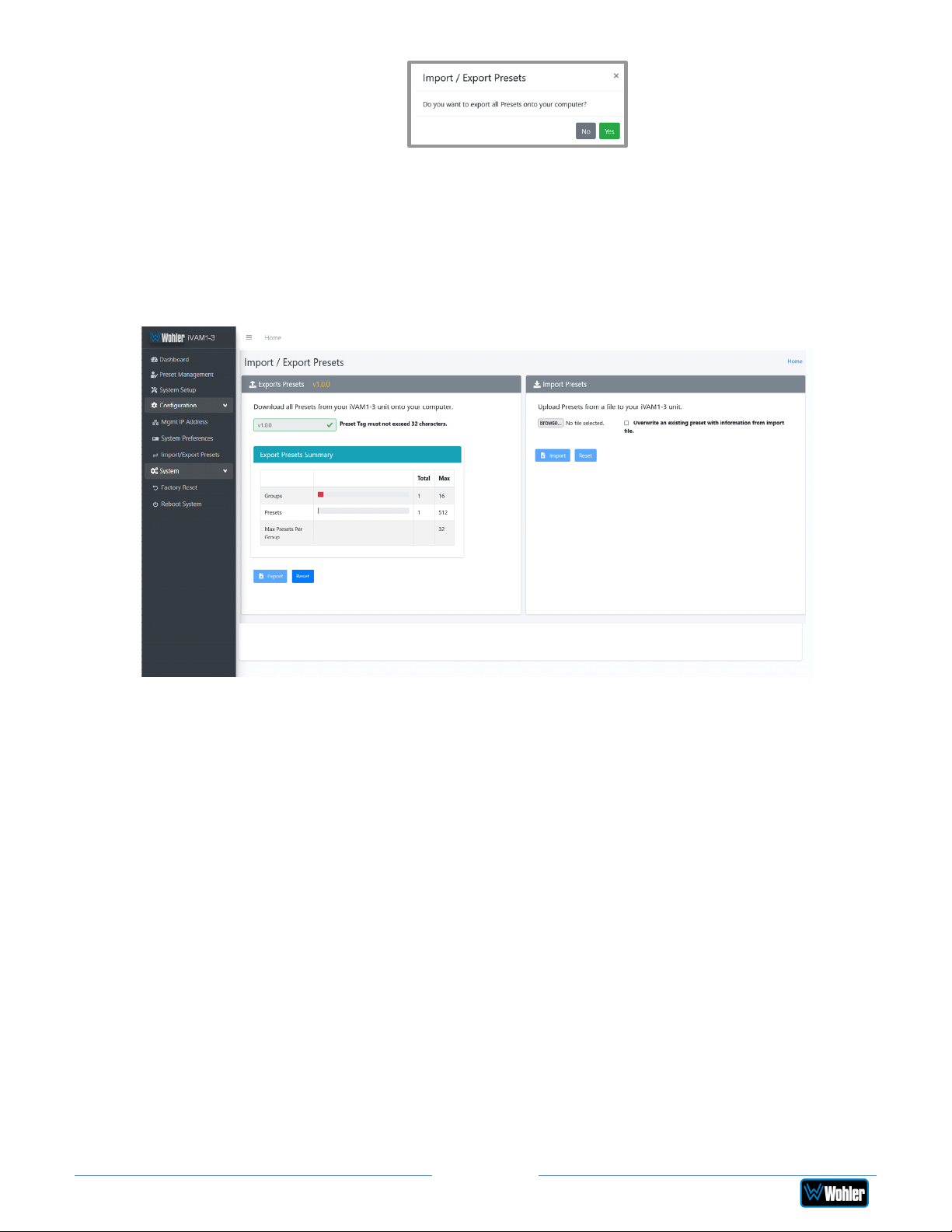
4. Click Yes to proceed with writing the Preset data to the hard drive. The
copying will proceed. After the Preset data has been written, the screen in
Figure 4-24 will appear, explaining what has been exported in an Export
Presets Summary. It will also note whether there were any errors in the
process. If there were any errors, repeat these steps to try again.
Figure 4–24: Database Export
Import Configuration
Use the following steps to copy the Preset configuration into the iAM2-8:
1. Click the Browse button as shown in Figure 4-24 and select the Preset Tag
you would like to import.
2. If you want to allow existing Presets to be overwritten with imported Presets
of the same name, check the Overwrite an existing Preset box. It is a
good idea to do this.
3. Click the Import button. The copying will proceed. When complete, the
screen in Figure 4-25 will appear, explaining what has been imported in an
Import Presets Summary. It will also note whether there were any errors in
the process. If there were any errors, repeat these steps to try again.
Page 81
iAM2-8
Page 82
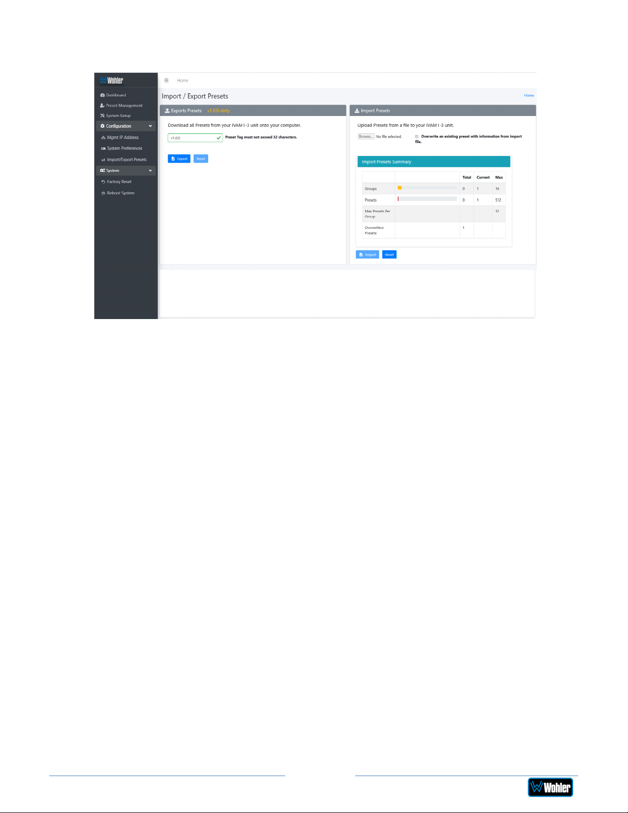
Figure 4–25: Database Import
iVAM1-3
Page 82
iAM2-8
Page 83
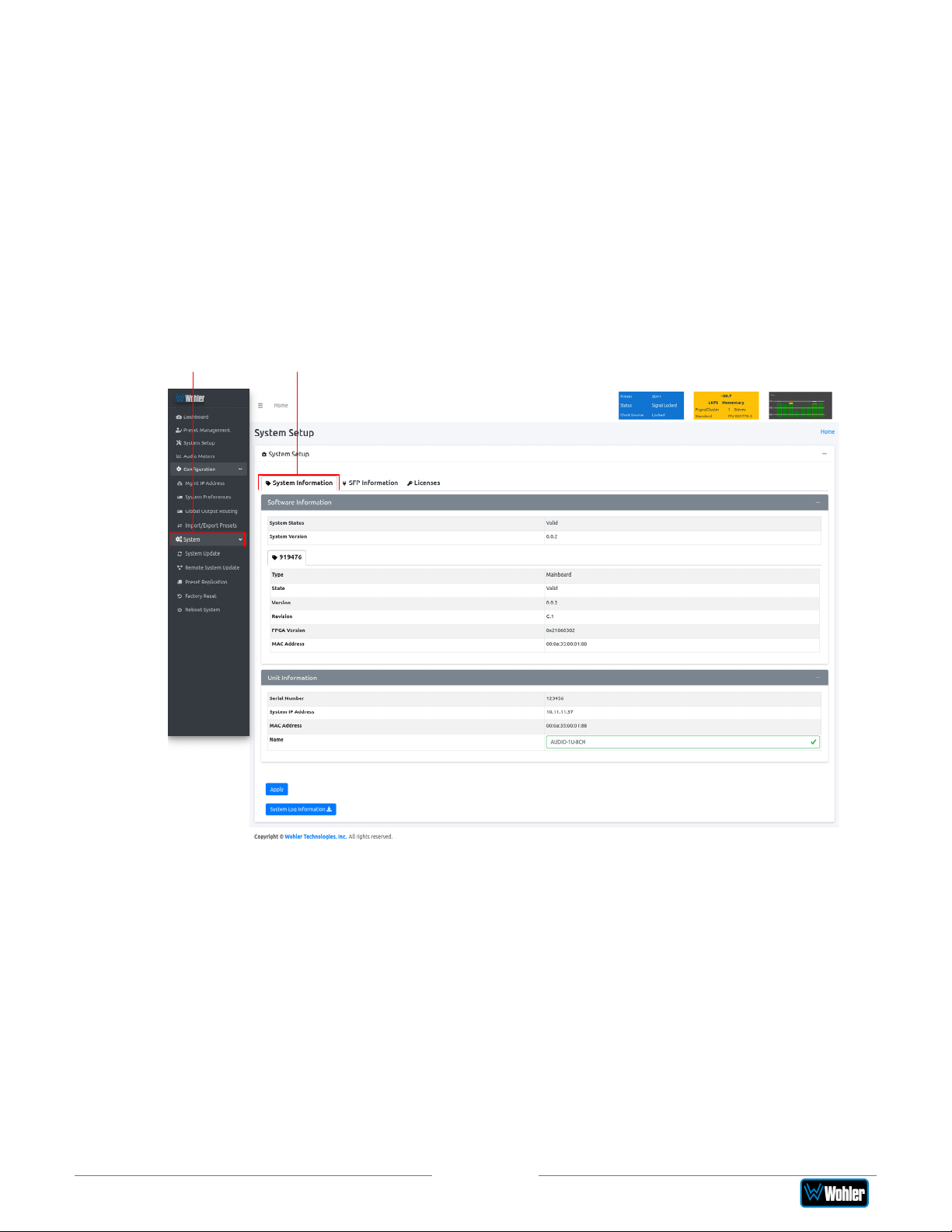
System
Click on System to find three tabs, each containing important information about
the iAM2-8. These tabs are explained in the following three sections.
System Information
This tab displays a variety of information about the iAM2-8. It is shown in Figure 4-
26. This information could be useful to view if you are contacting Wohler Technical
Service.
Figure 4–26: System Information Tab
System
System Information
iAM-AUDIO2-8
Page 83
iAM2-8
Page 84
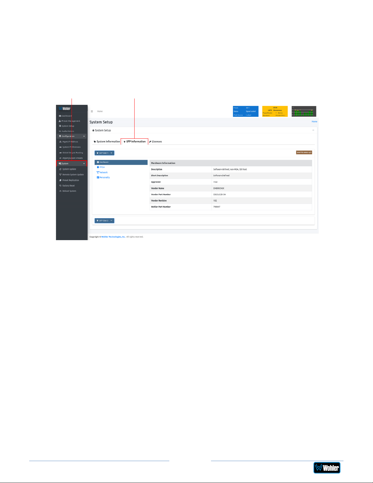
SFP Information
This tab displays a variety of information about the module inserted into the SFP
slot on the rear panel of the iAM2-8. It is shown in Figure 4-27. This information
could be useful to view if you need to ascertain what module, if any, is installed, or
if you are contacting Wohler Technical Service.
Figure 4-27: SFP Information Tab
System SFP Information
iAM-AUDIO2-8
Note: SFP Information, as shown in lower half of Figure 4-27, can be used to
retrieve the 2110 or 2022 SFP Module network configurations. This is useful if the
customer forgets the IP address assigned to these SFP modules.
Page 84
iAM2-8
Page 85
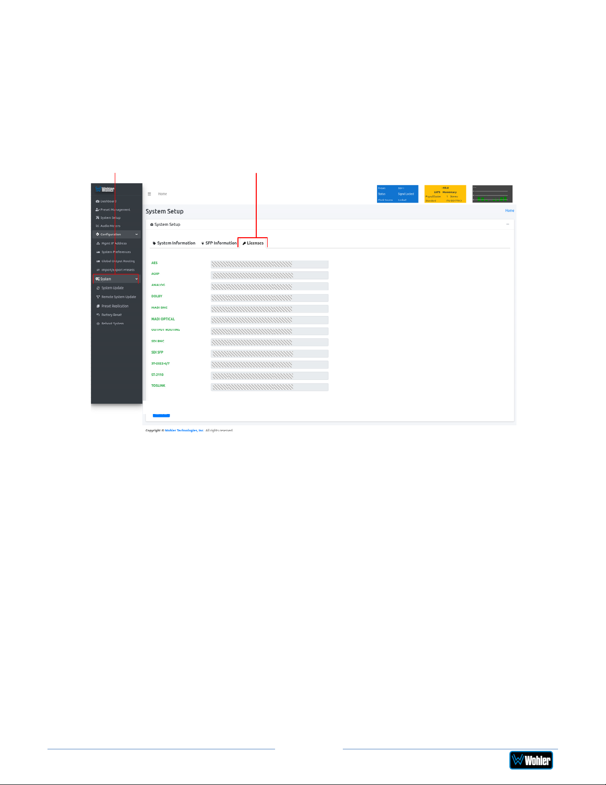
Licenses
This tab displays the license number for each of the modules or features in the
iAM2-8. It is shown in Figure 4-28. You will use this tab to enter any new license
numbers that you purchase. Contact Wohler Sales to obtain new license numbers.
If you need help, Wohler Technical Service will be happy to assist you in installing
these numbers.
Figure 4-28: Licenses Tab
System Licenses
iAM-AUDIO2-8
The example above shows an iAM2-8 with license keys for inputs and license keys
for SFP modules installed.
To enter the license key provided to you by Wohler Customer Service, use the
following steps:
1. Click the field to the right of the input or module desired.
2. Enter the license key in the box.
3. Repeat Steps 1 and 2 for any other license keys that you want to enter.
4. Click the Refresh button to save the information. Each new license will be
immediately available for use.
Page 85
iAM2-8
Page 86
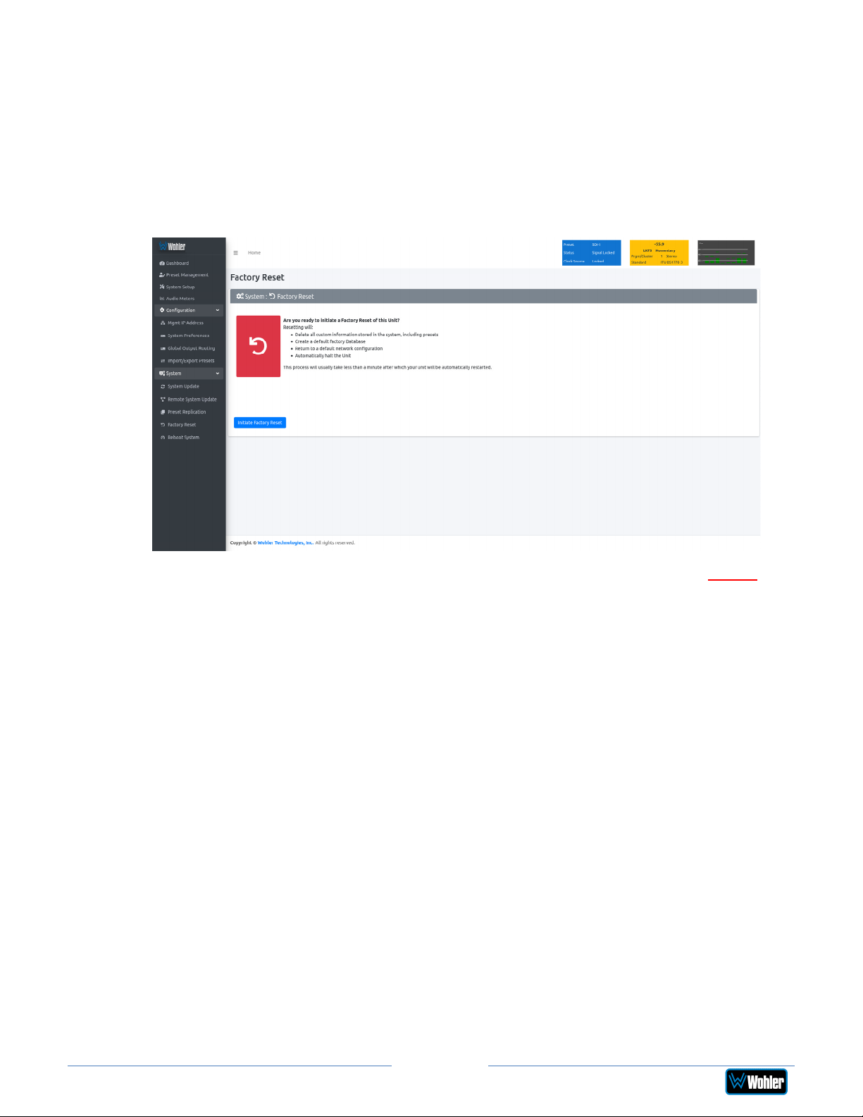
Factory Reset
The Factory Reset function should be used with caution. It deletes all of the
settings you have programmed into the system. It returns the system to the way it
was when received new from the factory. After using this function, you will need to
reprogram everything from the start.
iAM-AUDIO2-8
Figure 4–29: Factory Reset
If you have any doubt as to whether you should perform a Factory Reset, do not
click the Initiate Factory Reset button. Contact Wohler Technical Service for
advice.
Note: Factory Reset will also reset your IP address to the default one. After a
Factory Reset, the IP Settings will need to be updated. The default IP address for
the unit is determined based upon the Mac address. It is 169.254.1.xx where xx is
the last octet of the management Mac address. For example, if the Mac address is
b4:ed:54:d0:04:28 then the IP address would be 169.254.1.40 (40 is the decimal
equivalent for the last octet of Mac address 28.)
Page 86
iAM2-8
Page 87
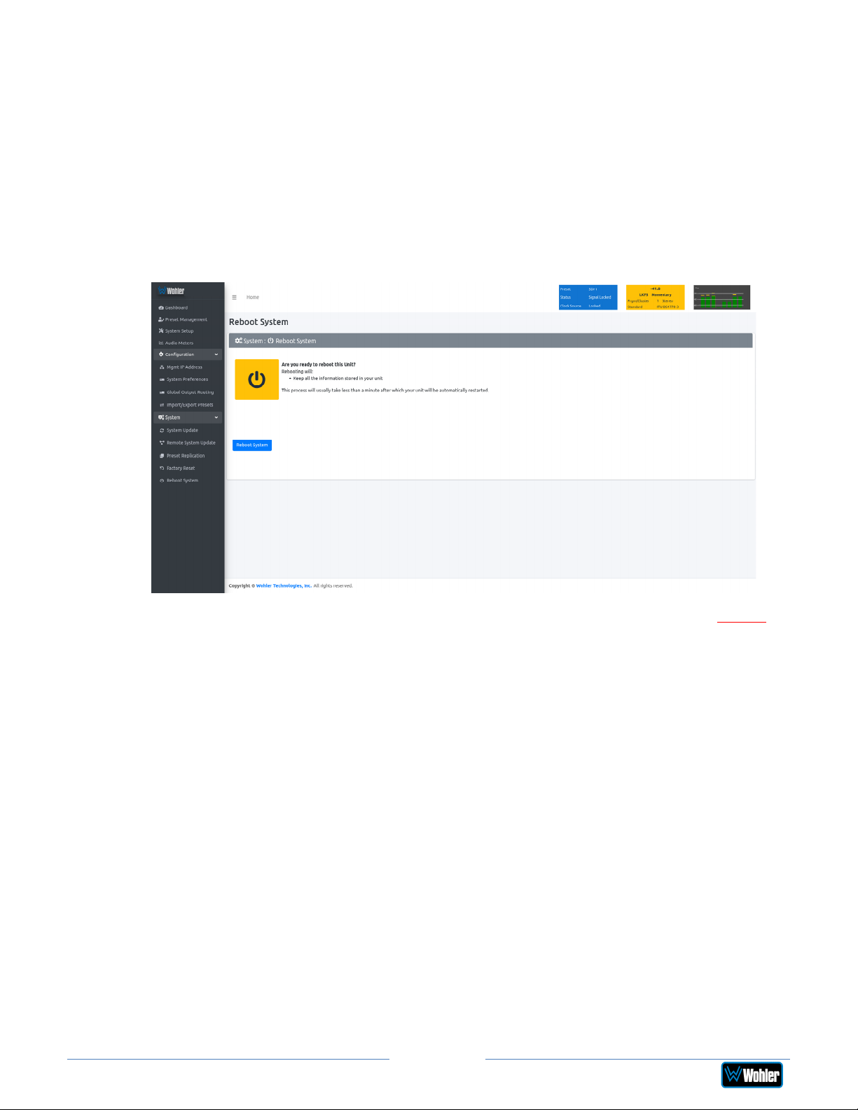
Reboot System
The Reboot System page allows you to reboot an iAM2-8 remotely. The Reboot
System page is shown in Figure 4-30. This function is normally only used upon
request from Wohler Technical Service to troubleshoot or correct an issue.
The Reboot System function should be used with a bit of caution. It puts the
iAM2-8 out of service for several minutes while it is rebooting, and this may
unexpectedly interfere with the use of the product by the remote operator.
iAM-AUDIO2-8
Figure 4–30: Reboot System
If you have any doubt as to whether you should reboot the remote iAM2-8, do not
click the Reboot System button. Contact Wohler Technical Service for advice.
Page 87
iAM2-8
Page 88

APPENDIX A: Software Upgrades
Introduction
This chapter describes how to download a software update file to your computer,
transfer it to a USB flash drive and install the updated into an iAM2-8.
Download the Software
The iAM2-8 software update can be found at http://www.wohler.com, under
Product Downloads on the Products > iAM2-8 page, in Support > Downloads >
Drivers & Software, or contact Wohler Customer Support for more information.
Unzip the downloaded update files to reveal two files. One will have a suffix of .wx
and the other will have a suffix of .md5sum. Both files are needed for the upgrade.
Update Methods
There are several software update methods. Select one of them, depending upon
your needs:
1. Local update from the front panel of the iAM2-8: This straightforward method
does not require the use of the Web GUI. A flash drive containing the update
is plugged into the front panel USB socket and the update is then
accomplished using the self-contained menu system. If this method seems
most suitable, then refer to the Local Update from the Front Panel section of
this chapter.
2. Remote update using the Web GUI with a flash drive connected to the iAM28: It may be more convenient to update the product using a flash drive
plugged into its front panel USB socket, but controlled remotely via the Web
GUI. To update the product this way, refer to the Updating via the Web GUI
section of this chapter.
3. Remote update without a flash drive: This method allows you to update a
networked iAM2-8 remotely without plugging a flash drive into its front panel
USB socket. To update the product this way, refer to the Updating an iAM2-8
Remotely section of this chapter.
4. Update multiple units remotely at once: This method allows you to update
multiple networked iAM2-8 units at once, without plugging flash drives into
their front panel USB sockets. To update products this way, refer to the
Updating Multiple iAM2-8 Units Remotely section of this chapter.
Page 88
iAM2-8
Page 89
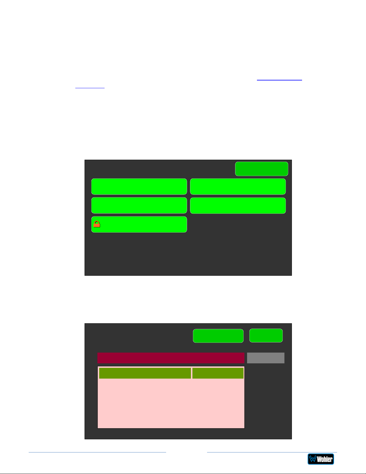
Local Update from the Front Panel
Use the following steps to update the iAM2-8 software:
1. Copy the unzipped Wohler Update Package file(s) from your computer to the
root directory (not inside of a folder) of a USB flash drive. It must be FAT32
file type, and does not need to be empty. Refer to the Download the
Software section of this chapter for the specifics of download and file transfer
to the USB flash drive.
2. Insert the USB flash drive with iAM2-8 update package(s) into the front panel
USB jack.
3. From the Menu screen, touch System Options. The screen shown in Figure
A-1 will appear.
Figure A-1 - System Options Screen
System Options
Menu
Network Settings System Reboot
System Update
Factory Reset
Passcode Settings
4. In the System Options menu, touch System Update. The Software
Upgrade screen will appear, as shown in Figure A-2.
Figure A-2 - Software Upgrade Screen
System Update
Refresh
Back
Software Version 1.1.3
WOHLER iAM-AUDIO2-8 1.1.3
Page 89
iAM2-8
Page 90
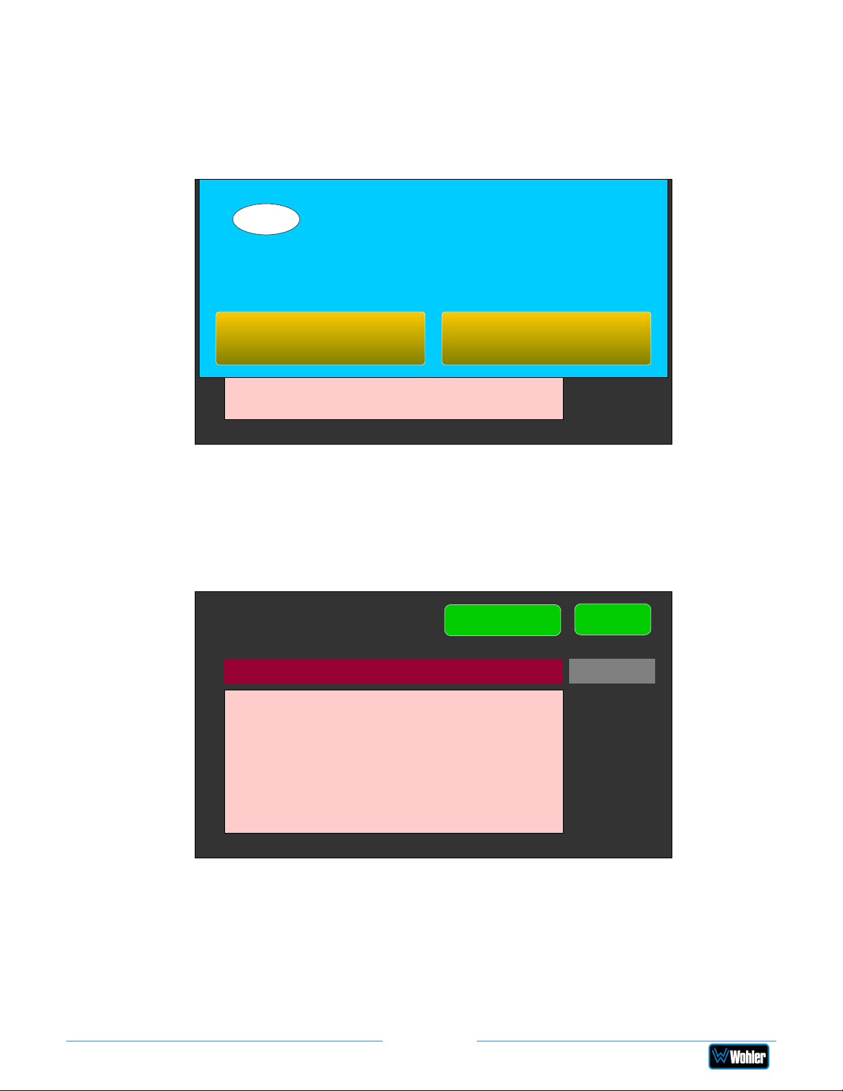
5. The new software version that is in the flash drive will be shown in the
Software Version screen. To cancel the upgrade at this point for any
reason, touch Back. To proceed, touch the software version entry in the
Software Version screen. A screen will appear, as shown in Figure A-3.
Figure A-3 - Upgrade Verify
Software Upgrade
?
Are you sure?
Do you want to Update your System to
Software Version 3.4-39
1.1.3?
Wohler iAM-AUDIO 3.4-56
Yes No
Back
6. To proceed, touch Yes. To back out, touch No. After you touch Yes, the
screens will change, as shown in Figure A-4. The message on this screen will
change as the upgrade progresses. The left screen will display, "Software
Upgrade in Progress" until the upgrade is complete.
Figure A-4 - Upgrading System
System Update
Refresh
Software Version 1.1.3
Upgrading System.
Installing Package
Back
7. After the software update starts, the text on the left screen will change
periodically to indicate the progression of the upgrade. The upgrade will take
5 minutes or more, after which the iAM2-8 will restart. After the system has
completed its restart cycle and is once again operational, you may then
remove the flash drive.
Page 90
iAM2-8
Page 91
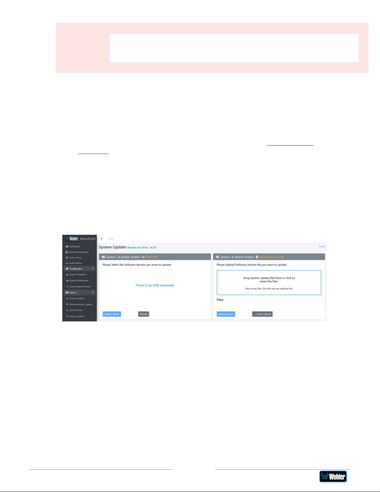
Important:
d crash the
Do not interrupt or remove power to the iAM2-8, or remove the
USB drive during the installation process. Doing so coul
iAM2-8 software.
Updating via the Web GUI using a Flash Drive
Use the following steps to update the iAM2-8 software:
1. Copy the unzipped Wohler Update Package file(s) from your computer to the
root directory (not inside of a folder) of a USB flash drive. It must be FAT32
file type, and does not need to be empty. Refer to the Download the
Software section of this chapter for the specifics of download and file transfer
to the USB flash drive.
2. Connect to the iAM2-8 with the Wohler Web GUI. Navigate to the System |
System Update menu, as shown in Figure A-5. If the iAM2-8 has recently
been powered and it contains the Dolby Decoder option, then a message may
appear asking you to wait for a number of seconds so that the decoder will
be operational.
Figure A-5 – System Update Menu
3. Click on the Refresh button.
4. Available software update(s) are shown as in Figure A-6. Click the one you
want, followed by clicking the System Update button.
iAM2-8
Page 91
Page 92
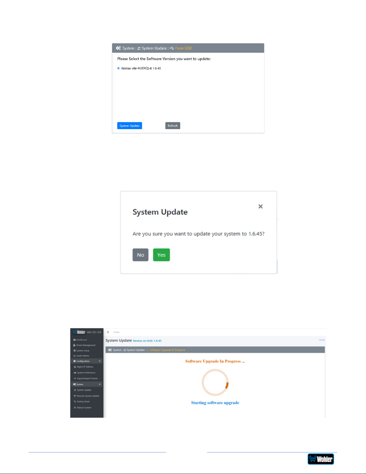
Figure A-6 – Available Software Updates
5. After clicking the System Update button, a verification screen displays as
shown in Figure A-7. If you agree that the correct update version has been
selected, click the Yes button.
Figure A-7 – System Update Verification
6. Next, the update begins, showing the screen in Figure A-8. The circle in the
center of the screen, along with status messages below it, will indicate the
progress of the update.
Figure A-8 – Software Upgrade in Progress
7. At this point, wait for the update to complete. It may take several minutes,
but it is critical not to disturb the iAM2-8 or the Web GUI until the
iAM2-8
Page 92
Page 93
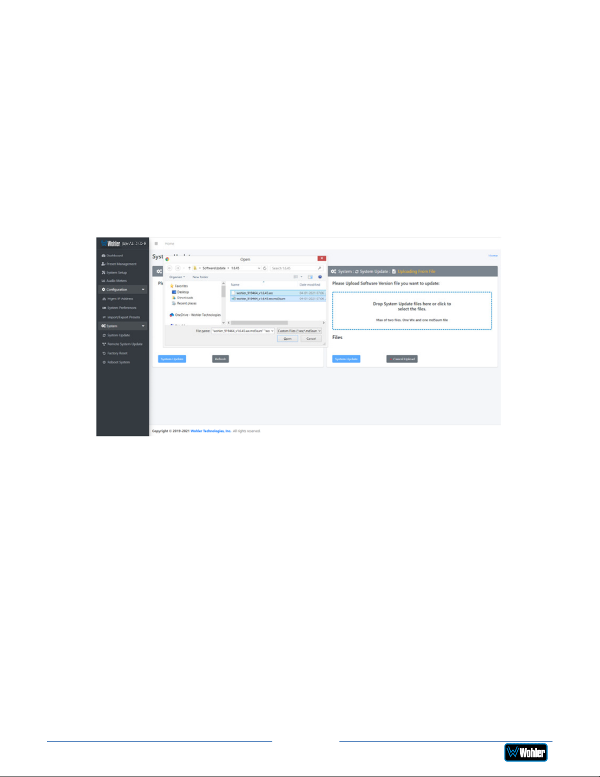
update process is complete. When it is complete, the iAM2-8 will restart.
Updating an iAM2-8 Remotely
Use the following steps to update the iAM2-8 software:
1. The Software Update files you downloaded earlier must be in the same
computer that is running the Web GUI. Connect to the iAM2-8 with the
Wohler Web GUI. Navigate to the System | System Update menu. Click
within the large blue dotted line rectangle at the right of the screen. A file
selection window will open, as shown in Figure A-9.
Figure A-9 – System Update Menu
2. Click the two update files. One will have a suffix of .wx and the other will
have a suffix of .md5sum. If you make a mistake and click the wrong file(s),
click the Cancel Upload button and try again. When the files have uploaded,
the System Update button will be enabled. Click it. If there is a problem
with the files as this point one of the screens shown in Figures A-10 or A-11
will appear. In that case follow the directions on the screen to retry. If there
are no problems, the update will proceed and the screen shown in Figure A-8
will appear.
iAM2-8
Page 93
Page 94
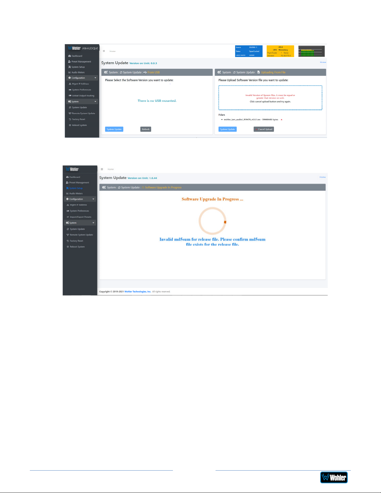
Figure A-10 – Invalid System File Version
Figure A-11 – Invalid Checksum
iAM-AUDIO2-8
iAM2-8
3. At this point, wait for the update to complete. It may take several minutes,
but it is critical not to disturb the iAM2-8 or the Web GUI until the
update process is complete. When it is complete, the iAM2-8 will restart.
Page 94
Page 95
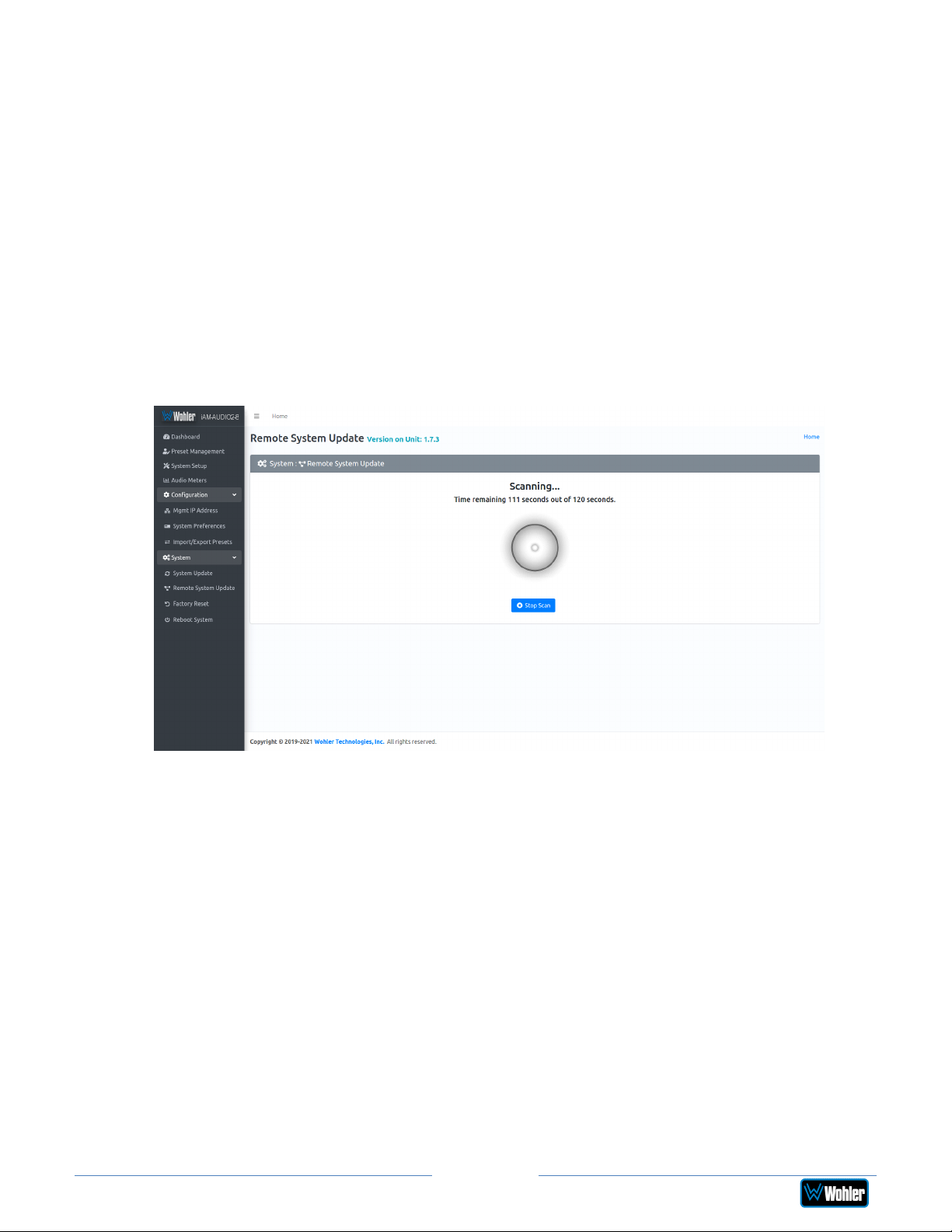
Updating Multiple Units Remotely
Use the following steps to update one or more iAM2-8 units remotely by
transferring the software from a previously updated iAM2-8:
1. If any of the iAM2-8 units that you intend to update remotely may be in use,
contact the people using them and let them know what you will be doing.
The iAM2-8 units being updated will be temporarily out of service.
2. Use the Wohler Web GUI to connect to an iAM2-8 already containing the
latest update. This will be referred to as the Master Unit. Navigate to the
System | System Update | Remote System Update menu. The screen
shown in Figure A-12 will appear and the Web GUI will scan the network for
any active iAM2-8 units.
Figure A-12 – Scanning for iAM2-8 Units
iAM2-8
Note: The scanning process will take 2 minutes. Progress is shown on the
screen. If for some reason you would like to stop the scan prematurely, click the
Stop Scan button.
Important: Do not run the scanning or updating process from more than one
Master Unit at a time, to avoid problems. Although you may be updating
multiple units at the same time, never attempt this process from more than one
Master Unit.
3. When the scanning is complete, a list of found iAM2-8 units will be shown as
in Figure A-13. Click either Select All or click only the Target units that you
want to update.
Page 95
Page 96
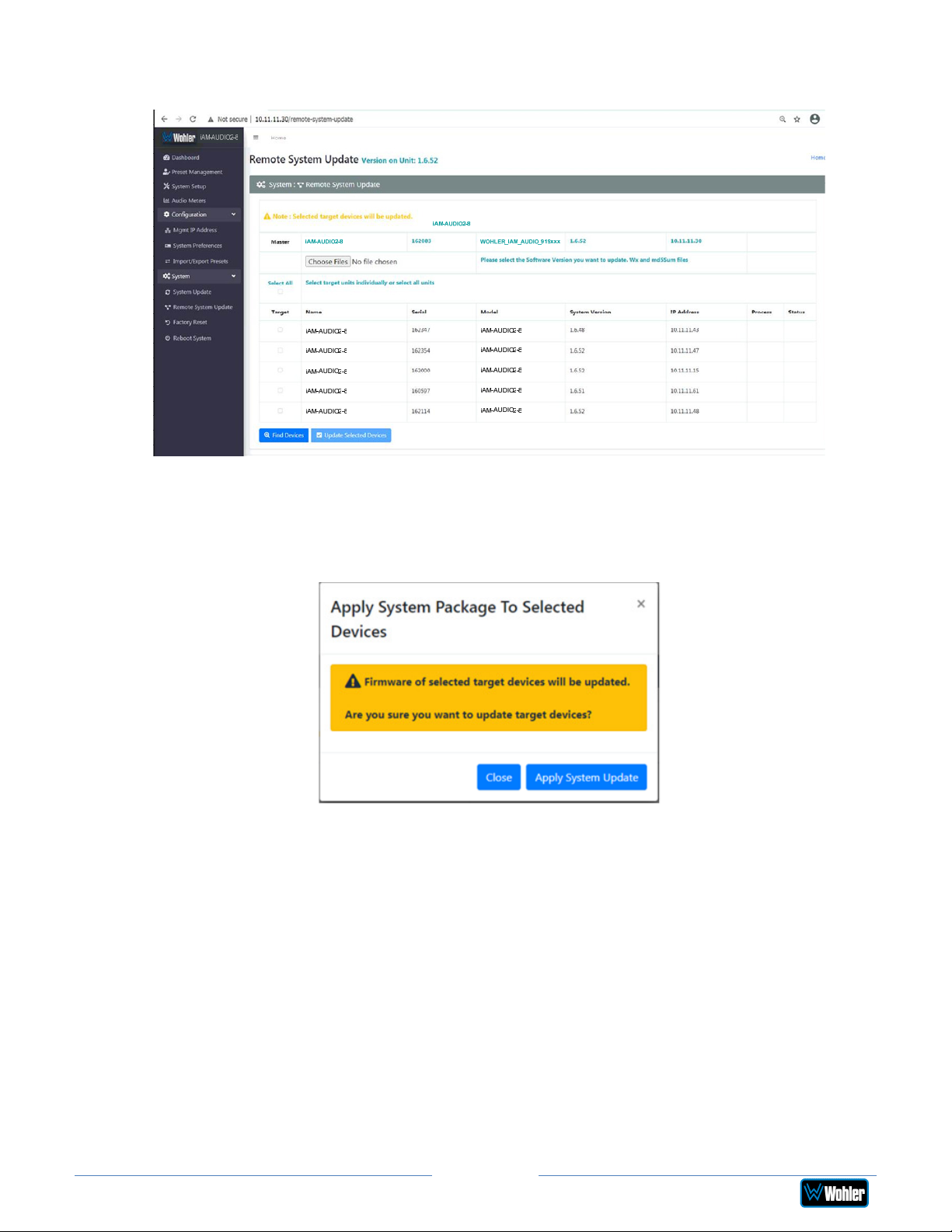
Figure A-13 – List of Found iAM2-8 Units
4. Then click Update Selected Devices. The window shown in Figure A-14 will
appear.
Figure A-14 – Apply System Package
5. Click Apply System Update. The screen shown in Figure A-15 will appear.
This screen contains a table showing the update progress of each of the
iAM2-8 units being updated.
Page 96
iAM2-8
Page 97
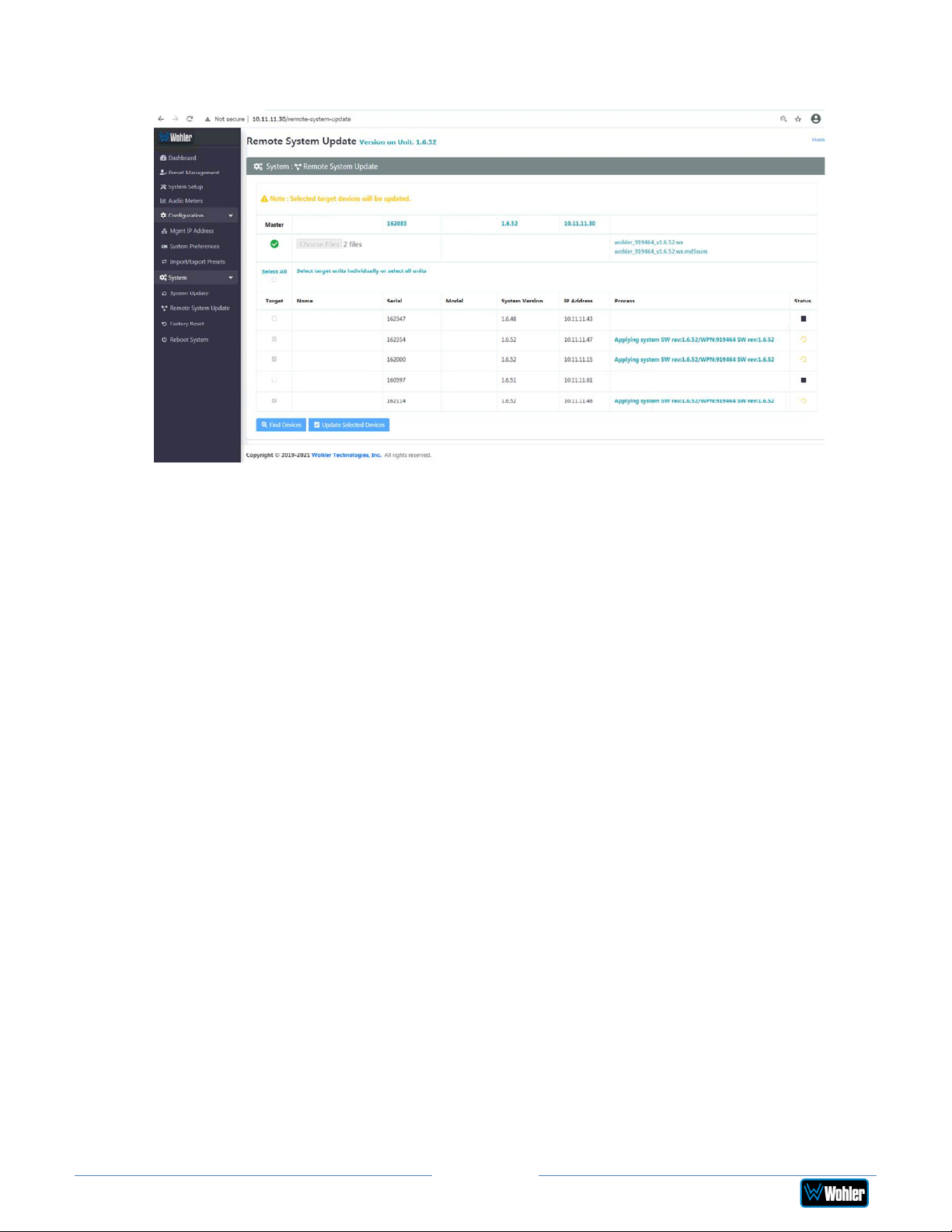
Figure A-15 – System Update Progress
iAM-AUDIO2-8
iAM-AUDIO-2 PLUS iAM-AUDIO2-8
Wohler iAM-AUDIO2-8 version 1.6.52 will be applied.
iAM-AUDIO2-8
iAM-AUDIO2-8
iAM-AUDIO2-8
iAM-AUDIO2-8
iAM-AUDIO2-8
iAM-AUDIO2-8
iAM-AUDIO2-8
iAM-AUDIO2-8
iAM-AUDIO2-8
iAM-AUDIO2-8
6. At this point, wait for each update to complete. It may take several minutes,
but it is critical not to disturb any of the iAM2-8 units or the Web GUI
until the update process is complete. When it is complete, each iAM2-8 will
restart.
Page 97
iAM2-8
Page 98

APPENDIX B: Dante Network Setup
Introduction
Installing the iAM2-8 into an existing and functioning Dante network is virtually
plug and play. The iAM rear panel AoIP jack supports 1Gb/s and 100Mb/s Ethernet
devices in Dante Audio over IP network configurations.
The AoIP option on the iAM2-8 supports Hitless and has 2 RJ-45 interfaces, a
primary interface and a secondary interface.
Additionally, an SFP slot is provided to receive the AoIP signal using network fiber
SFPs. These are 1G SFP slots. The SFP slot always acts as a primary interface.
On iAM2-8, the AoIP source can be selected through the Source Select option.
The iAM2-8 is set up at the Wohler factory to be used as a slave rather than a
master within the Dante network. Other devices or software, such as a Dante
Controller, are expected to be responsible for most device configurations and all
audio routing.
Please refer to the Dante Controller User Guide or other control device
documentation for specific network and device setup information. The next section
provides a guide to configuring the card and AOiP port.
What is in the iAM2-8 for Dante?
The Dante AOIP option consists of an Audinate Brooklyn II card directly connected
to the AOIP port. This port is dedicated to the card and should not be confused
with the Wohler unit Management port. These two ports must be on two different
subnets, one for the AOIP network and the other for access to the Wohler Web GUI
for management of the Wohler unit itself. Either one can be configured to have
static or DHCP addresses. The Wohler Web GUI indicates the presence of the Dante
card and the AOIP license but does not provide access to the various configuration
parameters internal to the card. The speed of the AOIP port is 1G default or
100Mbps.
The Audinate® Brooklyn II card has a simple process to set its initial IP address.
The initial factory setting for the card’s AOIP port is DHCP. When connected to a
DHCP based Dante network and the unit powered on, the Dante card sets the DHCP
server provided address as its default address.
Therefore, if the Dante network has a DHCP server, the unit can be inserted into
the network and can be configured further using the Audinate application, Dante
Controller, running on a host on the same DHCP based subnet.
If the Dante network is static based or if DHCP fails, the card sets a static Link Local
arbitrary address in the format 169.254.x.y, where x and y are each in the range 0
to 255. The mask is set to 255.255.0.0 to provide a ~65000 entry address space.
The Dante Controller host must also have a Link Local address to communicate with
the card over the unit’s AOIP port. Connect the AOIP port directly to a host (e.g.
laptop) running the Dante Controller, where the host address is preconfigured to an
Page 98
iAM2-8
Page 99
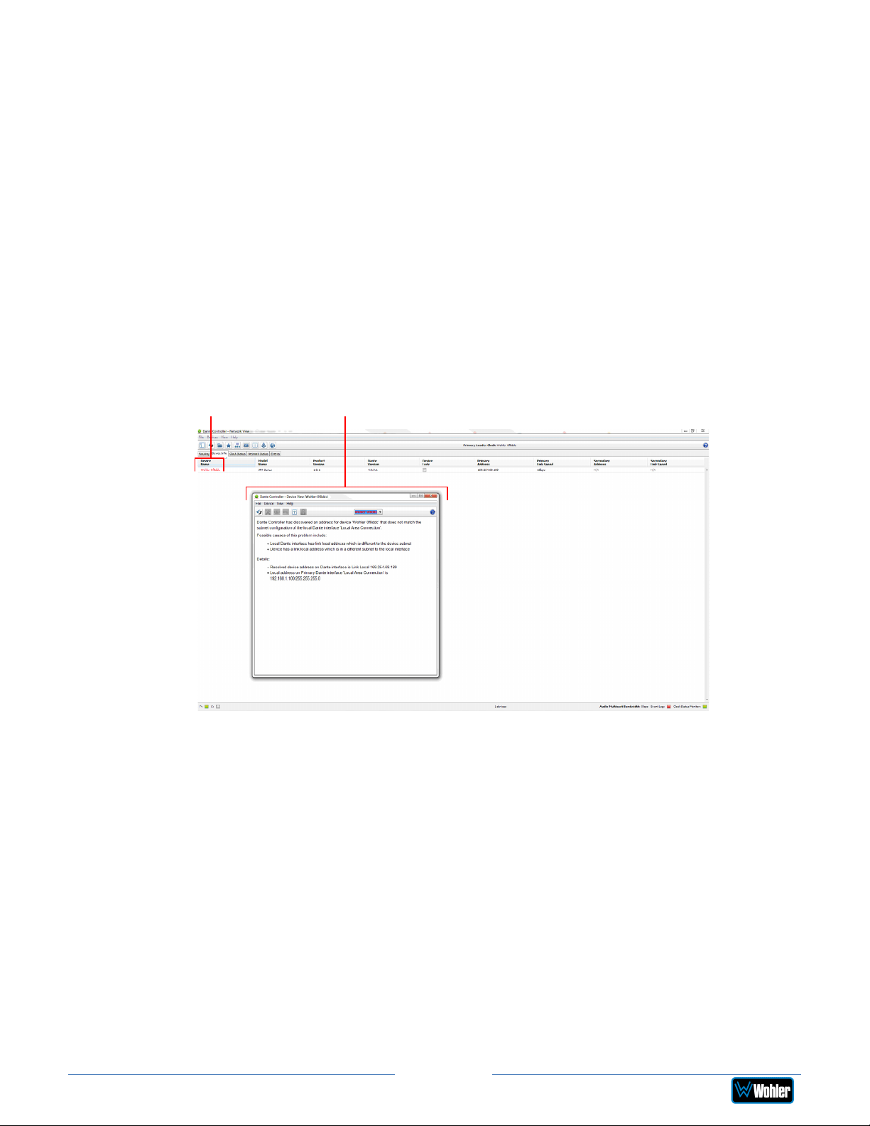
arbitrary Link Local address (169.254.x.y, mask 255.255.0.0). The connection can
be direct cable or through a switch. The Dante Controller Device Info tab shows
the card’s default static address, speed, etc. By double clicking its entry line,
additional settable parameters on the card can be reconfigured to be compatible
with the Dante network addressing and other parameters as necessary. When the
unit is rebooted on the Dante network, the card will be seen by the Dante Controller
used to manage the overall network.
If the Dante Controller Device Info tab detects the card but does not allow
modification and full presentation of card internals, the Card ID will be shown in
red, e.g. Wohler-xxxxxx where xxxxxx is the last 6 hex digits of the card MAC
address as shown in B-1. This usually indicates that the IP address of the card is
not in the same subnet as the Dante Controller host. By double clicking the ID, a
Device View screen will appear as also shown in Figure B-1 with further details
about the two incompatible addresses. Change the address of the host or move the
unit to another host with an address compatible with the Dante card.
Figure B-1 – Dante Controller Device Info Tab
Card ID Device View
Up to 8 of the 64 AoIP receive channels can be monitored at once in the iAM2-8.
The iAM2-8 transmits up to 20 channels. 1 to 8 are the monitored channel in
prefade mode. The remaining four are reserved for future use. Currently they are
mapped to channels being monitored on meter 1 to 4 in post-fade mode. The eight
iAM2-8 monitored channels are transmitted to the Dante network.
The iAM2-8 DanteTM AoIP is configured by the iAM2-8 to receive up to 64
channels and transmit 8 channels of Dante AoIP at 48 kHz or 44.1 kHz
audio sample rates. 48 kHz is the iAM default rate.
Sample rate selection is left up to the DanteTM Controller device or software. All
devices connected to each other through a Dante network must be set to the same
sample rate. Slight ticking may be heard in the iAM2-8 monitor when monitoring
different input types at different sample rates or if sources are asynchronous.
Page 99
iAM2-8
Page 100
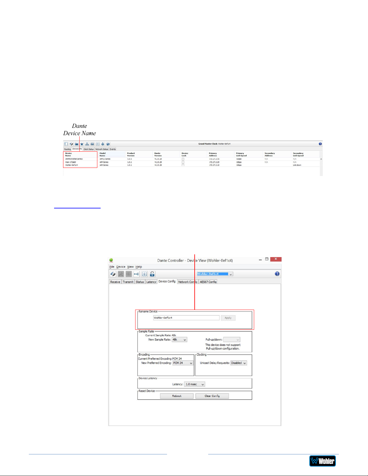
DanteTM Device Setup
The iAM2-8’s default Dante Device Name is “Wohler- …” followed by the last 6
digits of the Dante port MAC address, as shown in Figure B-2. This name can be
changed by the Dante Controller to appear that way on the network, but that will
not change the iAM2-8 unit name appearing on GUI pages and iAM2-8 Remote
Metering or Discovery pages.
Figure B–2: iAM2-8 Name
During initial setup, you may want to manually change the iAM unit Name in the
System Setup page to match the reassigned Dante Device Name for consistency.
Refer to Figure B-3.
Figure B–3: Rename iAM
Change the iAM
AoIP Name
Page 100
iAM2-8
 Loading...