

Page 1

AMP2-VSD and AMP2-VSDA
2U Digital Audio Speaker Monitor
With SDI Input and Output on BNC, Two AES Inputs on
BNC and XLR, Two AES Outputs From SDI on BNC, Four
Analog Inputs on XLR (-VSDA Only), Two Selected Analog
Stereo Outs on XLR, Four High-Res 53-Segment Level Meters,
Summable Channel Assignment, and Phase Indication
Document P/N 821581 Rev-B
User Manual
CONTENTS
Title and Contents ........................................................................
Important Safety Instructions and Introduction .................................................
Section 1: Features, Specs, and Installation ...................
Description and Features ...........................................................................
Applications and Specifications ..................................................................
Installation ...............................................................................................
Section 2: Operation ...................................................................
Front Panel Features ................................................................................
Rear Panel Features ..................................................................................
Audio Amplifier and Speaker Configuration ................................................
Balance Control Characteristics .................................................................
Section 3: Technical Information .........................................
General Technical Observations .................................................................
SDI to AES Converter Module (919096) ..................................................
AES to Analog Converter Module PCB (919050) ......................................
AES Digital Gain Calibration Fine Adjustment (919050) .............................
1
2
3
4
5
6
7
8
12
16
16
17
18
19
20
21
AES Error Jumper Locations (919050) ......................................................
Level Meter Rear Panel 6-Position DIP Switch Settings ..............................
Level Meter Internal 10-Position DIP Switch Settings .................................
Level Meter DIP Switch Locations ............................................................
Level Meter Alternative Scales ..................................................................
Level Meter Phase Correlation Featrure .....................................................
AMP2-VSD Interconnect Block Diagram ..................................................
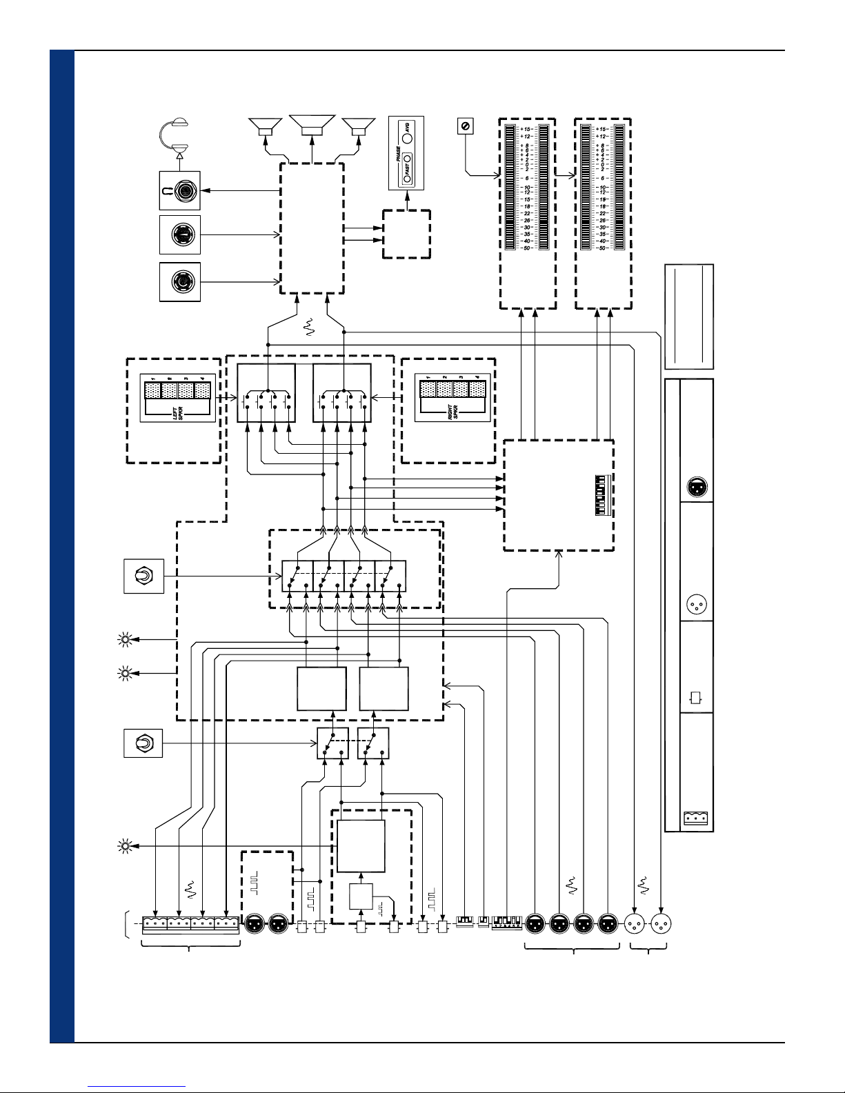
AMP2-VSDA Interconnect Block Diagram ...............................................
© 2004 Wohler Technologies Inc. ALL rights reserved
22
23
24
25
26
26
27
28
1
Page 2

Important Safety Instructions
1) Read these instructions.
2) Keep these instructions.
3) Heed all warnings.
4) Follow all instructions.
5) Do not use this apparatus near water.
6) Clean only with dry cloth.
7) Do not block any ventilation openings. Install in accordance with the manufacturer's instructions.
8) Do not install near any heat source such as radiators, heat registers, stoves, or other apparatus (including
amplifiers) that produce heat.
9) Do not defeat the safety purpose of the polarized or grounding-type plug. A polarized plug has two blades
with one wider than the other. A grounding type plug has two blades and a third grounding prong. The
wide blade or the third prong are provided for your safety. If the provided plug does not fit into your outlet,
consult an electrician for replacement of the obsolete outlet.
10) Protect the power cord from being walked on or pinched, particularly at plugs convenience receptacles
and the point where they exit from the apparatus.
11) Only use attachments/accessories specified by the manufacturer.
12) Use only with the cart stand, tripod, bracket, or table specified by the manufacturer, or sold with the
apparatus. When a cart is used, use caution when moving the cart/apparatus combination to avoid injury
from tip-over.
13) Unplug this apparatus during lightning storms or when unused for long periods of time.
14) Refer all servicing to qualified service personnel. Servicing is required when the apparatus has been
damaged in any way, such as when power-supply cord or plug is damaged, liquid has been spilled or
objects have fallen into the apparatus, the apparatus has been exposed to rain or moisture, does not
operate normally, or has been dropped.
15) Do not expose this apparatus to rain or moisture.
16) The apparatus shall be connected to a mains socket outlet with a protective earthing connection.
CAUTION!
In products featuring an audio amplifier and speakers, the surface at the side of the
unit, where the audio amplifier heat sink is internally attached, may get very hot after
extended operation. When operating the unit excercise caution when touching this
surface and ensure that external materials which may be adversely affected by heat
are not in contact with it. There is a Hot Surface label (see diagram) attached to the
aforementioned surface of the product.
Introduction
Congratulations on your selection of a Wohler Technologies product. We are confident it represents the best performance and value
available, and we guarantee your satisfaction with it.
If you have questions or comments you may contact us at:
Phone: (510) 870-0810 Fax: (510) 870-0811
www.wohler.com [email protected]
2
© 2007 Wohler Technologies, Inc. ALL rights reserved
Wohler Technologies, Inc.
31055 Huntwood Avenue
Hayward, CA 94544
US Toll-Free: 1-888-596-4537
Page 3

AMP2-VSD and AMP2-VSDA User Manual P/N 821581 Rev-B
Section 1
General Features
and Specifications
Description
Features
Applications
Specifications
Installation
Sect. 1: General Features and Specifications
Congratulations on your selection of a Wohler Technologies AMP2-VSD or AMP2-VSDA audio monitor unit. We are confident it
represents the best performance and value available, and we guarantee your satisfaction with it.
If you have questions or comments you may contact us at:
© 2004 Wohler Technologies Inc. ALL rights reserved
3
Page 4

AMP2-VSD and AMP2-VSDA User Manual P/N 821581 Rev-B
Section 1: Features, Specs, and Installation
AMP2-VSD and AMP2-VSDA
Powered Audio Monitors
AMP2-VSD Front Panel
AMP2-VSDA Front Panel
Description
The AMP2-VSD and AMP2-VSDA are monitors capable of audibly monitoring up to four source channels through a stereo
speaker system while simultaneously visually monitoring all four channels of the selected source via four high-resolution 53-segment
LED bargraph level meters. Both models process digital AES and SDI audio signals, while the AMP2-VSDA is also capable of
processing up to four analog audio signals. Two banks of four buttons on the front panel are used to independently assign from one
to four (summed) channels to each of the two (left and right) speaker channels. AES signal status is indicated by two bi-color (red/
green) LEDs. SDI signal status is indicated by one bi-color (red/green) LED. Features include a ganged stereo volume control and
balance pot, power indication LED, and headphone output. Output limiter circuits are incorporated to protect the speakers, and
extensive magnetic shielding allows placement immediately adjacent to video monitors with no color impurities. Wohler Technologies
proprietary three-LED stereo phase indication feature allows monitoring of phase relationships of the selected stereo inputs.
Rear panels for these monitors feature an SDI input and loop-through on BNC connectors, two AES inputs on unbalanced BNC
connectors, two alternate AES inputs on balanced XLR connectors, two AES outputs (converted from the SDI input) on BNC
connectors, and a stereo analog output of the channels assigned to the left and right speakers on two balanced XLR connectors. The
AMP2-VSDA additionally features four analog inputs on balanced female XLR connectors.
All AMP2 Series units contain three audiophile-quality drivers and three power amplifiers; two amplifiers (and two speakers) that
reproduce midrange and high frequency information in stereo, and a third amp/driver combination (and speaker) that handles
summed Low Frequency (LF) information below the 500 Hz crossover point. The AMP2 Series unique audio design has two
important advantages. First, it provides optimally focused sound in an Ultra Near Field tm (1 to 3 feet) environment. This allows
higher SPL for the operator while reducing overall ambient sound and adjacent bay crosstalk. Second, electronic rather than
acoustic cancellation of bass frequencies provides positive audible detection of reversed polarity (“out of phase”) audio feeds.
• 104 dB SPL at two feet
• Only two rack spaces high
• Excellent high frequency response for positive detection of
background whine and noise
• Audible and visual indication of phase/polarity problems
• Thorough magnetic shielding for placement next to video monitors
•
Four 53-segment high-resolution tri-color bargraph level meters:
-Selectable Input Referrence Level (0, +4, +6, or +8 dBu)
-Selectable Display Mode (VU Only, VU/PPM, or PPM Only)
-Selectable Peak Hold (Manual, 3-Second, 10-Second, or Off)
-Selectable PPM Ballistics (Type I, Type II, DIN 45406, or
SSRT)
-Selectable alternate Bargraph Scales (Extended VU, VU, BBC,
NORDIC, or DIN)
-Selectable Phase Correlation feature
• SDI input and loop-through on unbalanced BNC connectors
4
© 2004 Wohler Technologies Inc. ALL rights reserved
Features
• Two AES/EBU inputs on unbalanced BNC connectors
• Two alternate AES/EBU inputs on balanced XLR connectors
• Four analog inputs on balanced XLR connectors (AMP2-VSDA
only)
• Two AES outputs (converted from SDI input) on BNC
• Four analog outputs (from selected digital source) on Phoenix
• Stereo analog output of the channels monitored by the left and
right speakers on two balanced XLR connectors
• Two banks of four push buttons for assigning single or
summed channels to the left and right speaker
• Select AES or SDI input source via a front panel toggle switch
• Select analog or selected digital source via front panel switch
• One SDI signal status/error indication LED
• Two AES signal status/error indication LEDs
• Headphone output
• Power indication LED
Page 5
AMP2-VSD and AMP2-VSDA User Manual P/N 821581 Rev-B Section 1: Features, Specs, and Installation
Applications
The AMP2-VSD and AMP2-VSDA are ideally suited for use in VTR bays, mobile production vehicles, teleconferencing installations,
multimedia systems, satellite links and cable TV facilities, and on-air radio studios. Designed and manufactured in the U.S., both
models are backed by a strong warranty and a satisfaction guaranteed return policy.
General Specifications
Input Connectors:
Analog Input Impedance:
Digital Input Impedance:
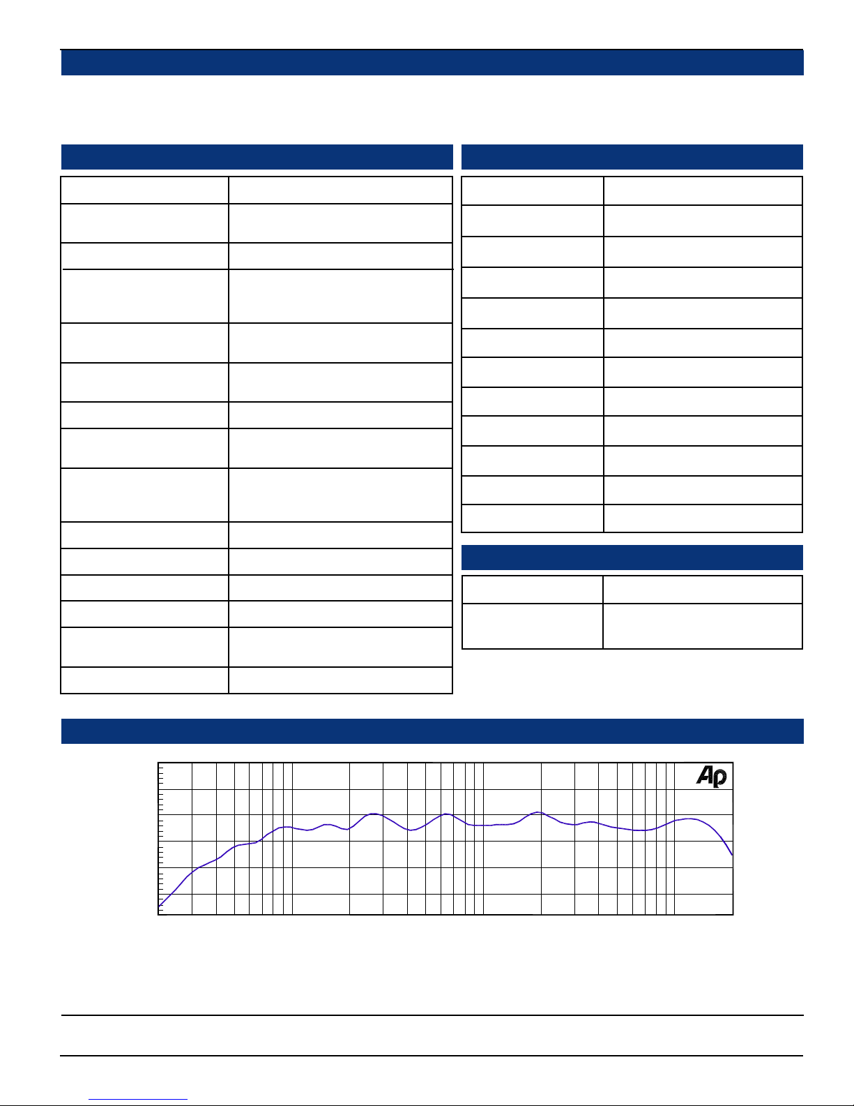
Peak Acoustic Out (@ 2 ft.):
Power Output,
RMS Each Side (4
RMS Bass (4
Frequency Response,
Sixth Octave:
Input Level for Maximum
Output (Volume Full On):
Hum and Noise (analog):
Distortion, Electrical:
Distortion, Acoustic:
Input Overload:
Converted Analog Out S/N:
ΩΩ
Ω):
ΩΩ
ΩΩ
Ω):
ΩΩ
SDI: BNC, AES: BNC/XLR, Analog: XLR
XLR: 70K Ω, bal. (AMP2-VSDA Only)
BNC: 75 Ω, unbal., XLR: 110 Ω, bal.
104 dB SPL
14 W transient / 10 W continuous
35 W transient / 25 W continuous
80 Hz - 16 kHz ± 5 dB)
(-10 dB @ 40 Hz, 20 kHZ)
0 dBv balanced / -10 dB unbalanced
Better than -68 dB below full output
Less than 0.15% at any level below
input threshold
6% or less at worst case frequencies
above 120 Hz, including cabinet
resonance; typically less than 1.5%
+26 dBv balanced
>90 dB
Level Meter Specifications
Level Meter Type:
Display Modes (select):
Peak Hold (select):
PPM Ballistics (select):
Reference Levels:
Phase Correlation:
Bargraph Scales:
Dynamic Range:
Midscale Resolution:
Segment Colors:
Scale:
Segment Size:
Physical Specifications
53-Segment tri-color (R,A,G) LED
VU, PPM, or VU/PPM
Manual, 3-sec, 10-sec, or OFF
Type 1, Type 2, DIN 45406, or SSRT
0, +4, +6, +8 dBu (DIP selectable)
ON or OFF
VU, Ext. VU, BBC, NORDIC, or DIN
65 dB
1 dB
Tricolor (green, amber, red)
+16 to -50 dB
.158" x .04" (4.0132 x 1.016 mm)
Converted Analog Out THD:
Magnetic Shielding:
Power Consumption
(Average Maximum):
AC Mains Input:
+10
0
d
-10
B
-20
-30
<0.008%
<0.8 Gauss any adjacent surface
45 W
100-240VAC, 50-60 Hz Universal
Audio Response Curve
Typical 1/6 Octave Audio Response Curve
Weight:
Dimensions (HxWxD):
18 lbs. (8.2 kg)
3.5 x 19 x 12 inches
(89 x 483 x 305 mm)
NOTE: For SDI specifications see page 19.
For AES specifications see page 20.
2k1k50020010050 20k20
Hz
5k
10k
Units are designed to meet, at time of manufacture, all currently applicable product safety and EMC requirements, such as those of
CE. 0 dbV ref. 0.775V RMS. Features and specifications subject to improvement without notice.
© 2004 Wohler Technologies Inc. ALL rights reserved
5
Page 6

AMP2-VSD and AMP2-VSDA User Manual P/N 821581 Rev-B
Section 1: Features, Specs, and Installation
Installation
Mounting
The unit should be mounted where convenient for operating persons, ideally at approximately ear/eye level for best high frequency
response and visual observation of the level meters. Its superior magnetic shielding eliminates concerns about locating it adjacent to most
types of CRT monitors, including even high-resolution color monitors.
Heat Dissipation
Heat dissipated by the speaker amps is conducted directly to the left side of the chassis; no special considerations for cooling are
necessary as long as the ambient temperature inside the rack area does not exceed approximately 40°C (104°F).
Sympathetic Vibration
Sympathetic vibration from other equipment (cables, etc.,) in the rack may be serious enough to interfere with the unit’s sound quality out
in the listening area. The use of thin card stock and/or felt or foam weather-stripping type materials between adjacent vibrating surfaces,
or tying up loose cables, etc., may be required to stop vibrations external to the unit.
Mechanical Bracing
Even though the unit is fairly heavy, the chassis is securely attached to the front panel at eight points along its surface, not just at the four
corners of the chassis ears. This feature will reduce or eliminate rear bracing requirements in many mobile/portable applications. The
weight of internal components is distributed fairly evenly around the unit.
Audio Connections
Connection of the audio feeds is straightforward. Please refer to the system interconnect block diagram on pages 27 and 28 for
clarification of the general signal paths into and out of the unit.
Care should be exercised to avoid mismatched cable types and other similar causes of undesired reflections in RF signal systems. If
severe enough, such reflections can result in corruption of the digital datastream.
AC Power
The unit's AC mains connection is via a standard IEC inlet, with safety ground connected directly to the unit's chassis. The
universal AC input (100-240VAC, 50/60Hz) switching power supply is a self-resetting sealed type, with automatic over-voltage
and over-current shutdown. There is no user-replaceable fuse in either the primary or secondary circuit.
6
© 2004 Wohler Technologies Inc. ALL rights reserved
Page 7

AMP2-VSD and AMP2-VSDA User Manual P/N 821581 Rev-B
Section 2
Operation
Front Panel Features
Rear Panel Features
Audio Amplifier and Speaker Configuration
Balance Control Characteristics
© 2004 Wohler Technologies Inc. ALL rights reserved
7
Page 8

AMP2-VSD and AMP2-VSDA User Manual P/N 821581 Rev-B
Section 2: Operation
Front Panel Features
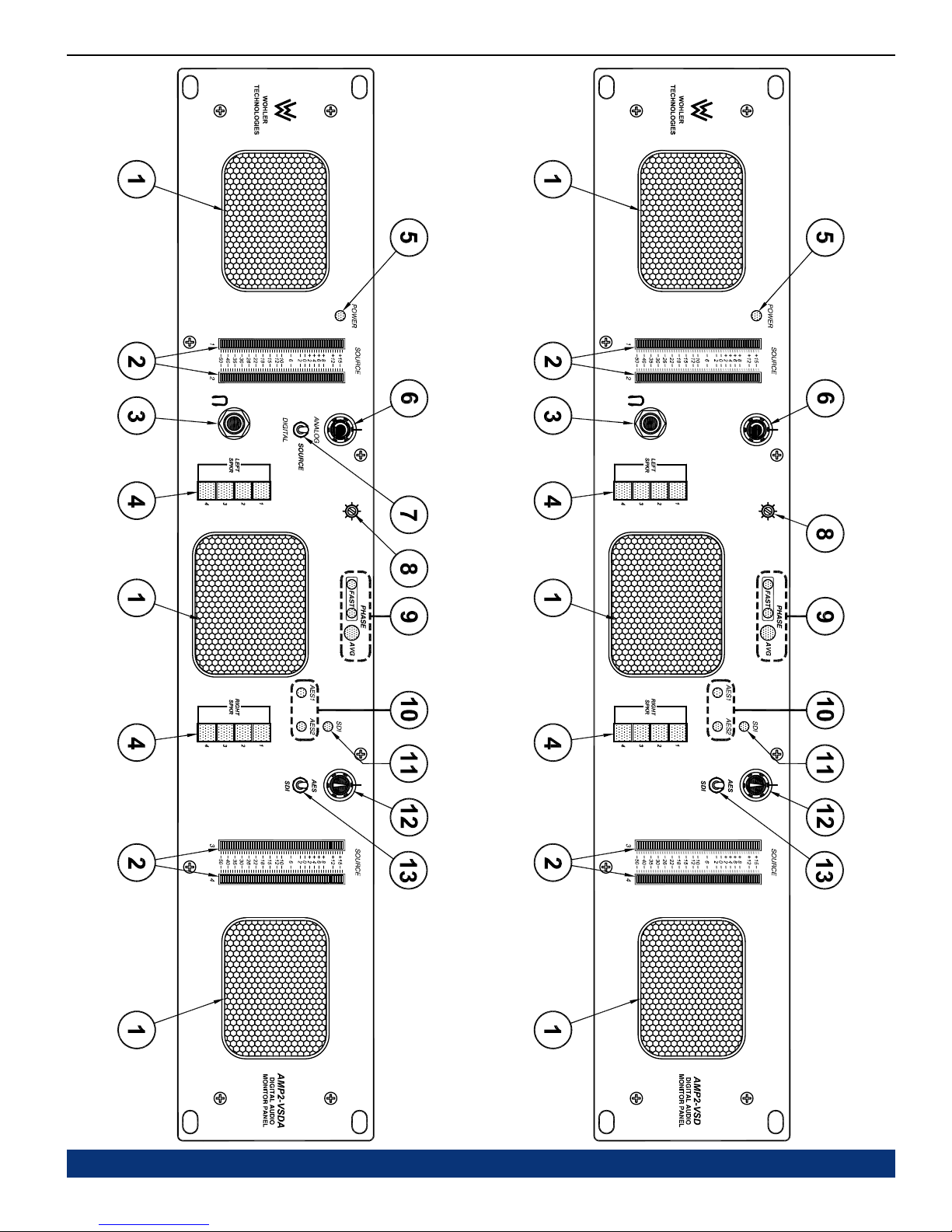
Please refer to Figure-2a on the facing page to familiarize yourself with the front panel features of the AMP2-VSD and
AMP2-VSDA units. The following sections describe these features and are referenced, by number, to Figure-2a.
Speakers
1
The AMP2 Series monitors feature two mid-range speakers (left and right) and one woofer speaker. Two amplifier/driver
combinations handle midrange and high frequency information in the left and right (stereo) speaker channels, while the third
channel reproduces and sums the left and right channel information below the 500 Hz crossover point in the woofer (bass)
speaker. Note that the woofer channel is NOT a dedicated LFE (subwoofer) or Center channel. See page 16 for more
information concerning the AMP2 Series audio amplifier/speaker configuration.
Audio Level Meter LED Bargraph Displays (1-4)
2
Audio levels for the four selected source channels are displayed via these four tri-color LED bargraph meters. The four
bargraph meters display audio levels for the digital or analog audio sources selected for monitoring. All bargraph LED
segments are of the tri-color type (GREEN, AMBER, RED) and are user adjustable for Referrence Level, Display Mode,
Peak Hold, PPM Ballistics, Alternate Bargraph Scales, and Phase Correlation via DIP switches on the rear panel and
inside the unit. For factory set and user adjustable level meter DIP switch settings, see pages 23 and 24. For more
information about the Phase Correlation feature, see page 26. For meter specifications, see page 5.
Headphone Jack
3
This jack accepts a standard 1/4” phone type stereo headphone plug. Select the headphone audio sources as you would for
the internal speakers. When you plug in headphones, the speakers will mute.
Speaker Assign Channel Buttons (Left and Right)
4
Use the left bank of four buttons to assign one to four of the four available channels for monitoring from the left speaker
channel. Use the right bank of four buttons to assign one to four of the four available channels for monitoring from the
right speaker channel. Channel buttons toggle On/Off and will light up BLUE to indicate they are selected.
Operation for channel selection for each bank of four buttons is as follows:
1)
Single Channel Select: Press and release a single channel button to select that channel (and deselect any previous
selection). Pressing and releasing the selected channel button again will deselect it.
Multi-Channel Select (Summing): Press and hold down a desired channel button, then press other channel buttons to
2)
add (sum) additional channels (or press any again to deselect). Release all buttons to accept the selection set. When
multiple channels are selected, pressing and holding an already selected channel button will allow further modification to
the selection set. Releasing all buttons accepts the new selection set. Pressing and immediately releasing an already
selected channel button will select only it and deselect all other channel selections. Note that if channels assigned to
either the left or right level meters are multi-channel (summed), then the respective level meter will indicate summed audio
levels.
If the user presses a previously selected (lighted) channel button, but then decides not to make any changes to the selection
set, the user should keep the button depressed for at least 1.5 seconds before releasing it. This will preserve the current
selection set as though the button was never pushed.
Power LED
5
This LED glows GREEN to indicate the unit is connected to mains power and an operation voltage is present.
Volume Control
6
This controls the loudness of the audio reproduced by the internal speakers or connected headphone. Clock-wise rotation
of this control increases the loudness of the monitored audio.
Analog/Digital Source Select Switch (AMP2-VSDA Only)
7
This two position toggle switch, featured only on the AMP2-VSDA, allows the operator to choose between the two primary
input sources; ANALOG or DIGITAL. When this toggle switch is set to ANALOG, the unit will monitor the signals as
input on the rear panel ANALOG IN XLR connectors (Item K, page 14). When this toggle switch is set to DIGITAL, the
unit will monitor the digital source (AES or SDI) as selected by the AES/SDI Digital Source Select Switch (Item 13,
page 10).
Bargraph Brightness Trim Pot
8
This control is recessed into the front panel and can be accessed using a small screwdriver. Turning it clockwise will
increase the relative brightness of all bargraph display LED segments. Adjusting this one control will simultaneously affect
the brightness of all bargraph displays on the front panel.
8
© 2004 Wohler Technologies Inc. ALL rights reserved
(Continued)
Page 9
AMP2-VSD and AMP2-VSDA User Manual P/N 821581 Rev-B Section 2: Operation
AMP2-VSDA AMP2-VSD
Figure-2a: Front Panel Features
© 2004 Wohler Technologies Inc. ALL rights reserved
9
Page 10

AMP2-VSD and AMP2-VSDA User Manual P/N 821581 Rev-B Section 2: Operation
Front Panel Features
(Continued)
Phase Indication LEDs
9
These three LEDs indicate the instantaneous and average phase (polarity) conditions between the two signals in the channel
pair (or downmix) assigned to the left and right speaker channels. The two smaller LEDs labeled FAST show instantaneous
phase relationships in the signal. The larger LED labeled AVG will indicate the average phase condition. Indication is as
follows:
• The left FAST LED glows (or blinks) GREEN for in-phase signals.
• The right FAST LED glows (or blinks) AMBER for out-of-phase signals.
• The large AVG LED indicates the average phase condition by glowing GREEN for in-phase signals, or RED for
out-of-phase signals.
In general, observing the AVG LED alone is sufficient for proper phase monitoring. While it is normal for stereo signals to
contain some intermittant instantaneous out-of-phase and in-phase conditions (FAST LEDs), a steady RED glow of the
AVG LED indicates an out-of-phase alarm condition.
AES Status LEDs (AES 1 and AES 2)
10
These two bi-color GREEN/RED LEDs (AES1 and AES2) indicate the input presence and status of the two AES input
signals. Either LED glows GREEN as long as a valid AES/EBU digital datastream for the associated input channel is
being received. Either LED glows RED to indicate errors in signal reception or data errors (if the data has been tagged
as inappropriate for conversion to analog by having the validity bit set). These LEDs function whether or not the AES
digital signals are selected for monitoring through the unit.
SDI Status LED
11
This bi-color (GREEN/RED) LED, labeled SDI, glows GREEN as long as a valid SDI digital datastream is being
received. It glows RED if TSR errors are present in the signal. If there is no SDI signal present the LED will be unlit.
This LED functions whether or not the SDI digital signal is selected for monitoring through the unit.
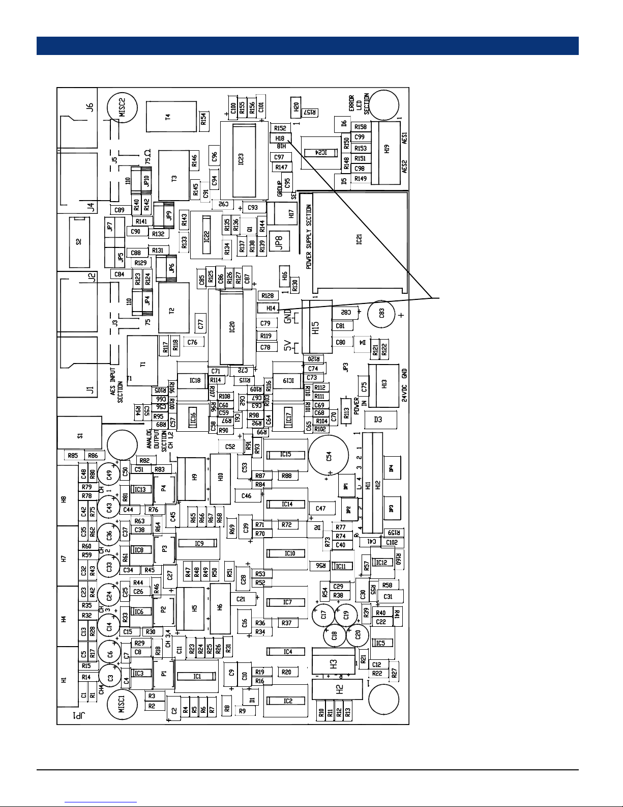
Note: If you wish to disable data error indication (and leave only indication of signal reception errors) you can place
jumpers on H14 and H18 of the 919050 AES-to-Analog conversion PCB. See page 22 for component locations.
Balance Control
12
This control changes the volume balance between the left and right speaker channels. Note that this control attenuates the
signal from the source, so that the left and right bass frequencies (summed together and reproduced in the woofer channel)
will respond to balance adjustments in tandem with the left and right speaker channels. See page 16 for more information
concerning the balance control characteristics.
AES/SDI Digital Source Select Switch
13
This two position toggle switch allows the operator to choose between the two digital input sources; SDI or AES.
When this toggle switch is set to AES, the unit will monitor the AES signals as input on the AES IN BNC or XLR
connectors (IN 1 and IN 2) on the rear panel (Item C or G, page 12). When this toggle switch is set to SDI, the unit will
monitor the SDI signals as input on the SDI IN BNC connector on the rear panel (Item D, page 12).
10
© 2004 Wohler Technologies Inc. ALL rights reserved
Page 11
AMP2-VSD and AMP2-VSDA User Manual P/N 821581 Rev-B Section 2: Operation
AMP2-VSDA AMP2-VSD
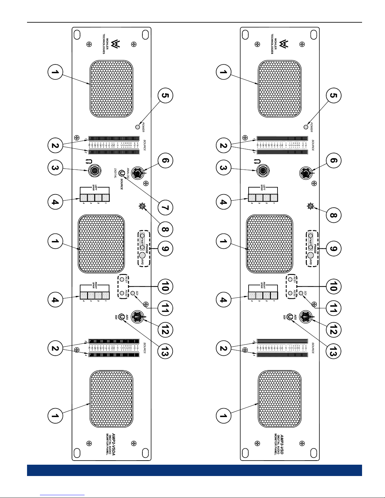
Figure-2a: Front Panel Features
© 2004 Wohler Technologies Inc. ALL rights reserved
11
Page 12
AMP2-VSD and AMP2-VSDA User Manual P/N 821581 Rev-B
Section 2: Operation
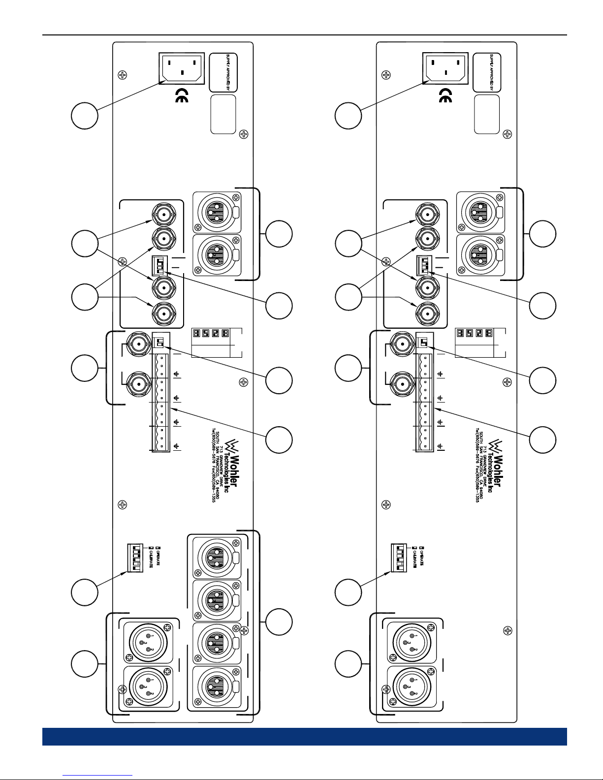
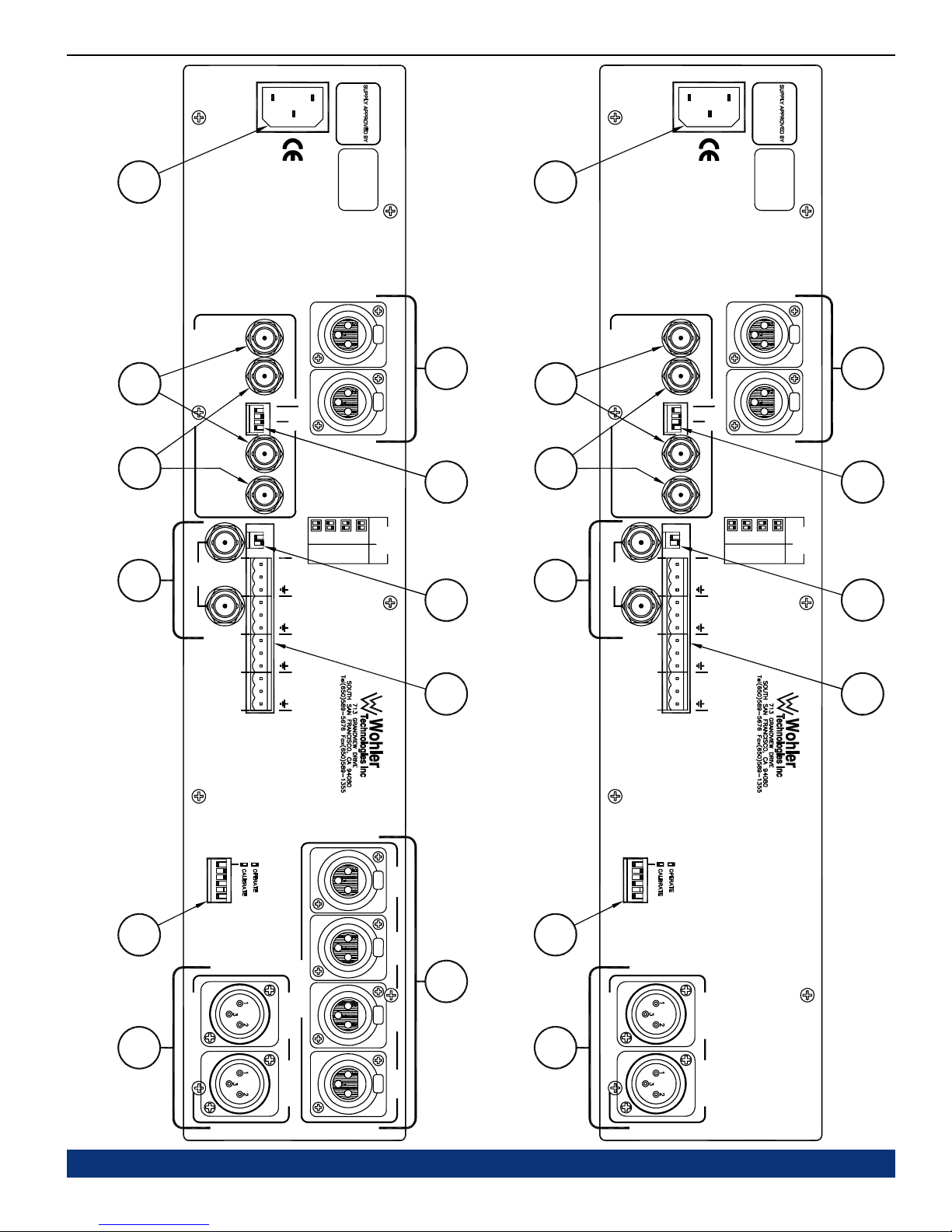
Rear Panel Features
Please refer to Figure-2b on the facing page to familiarize yourself with the rear panel features of the AMP2-VSD and AMP2-
VSDA unit. The following sections describe these features and are referenced, by letter, to Figure-2b.
Power Connector
A
Attach a standard IEC-320 power cord between this connector and mains power (100 - 250VAC, 50/60 Hz). The front panel
Power LED (Item 5, page 8) will glow GREEN to indicate operating voltages are present.
AES Input Unbalanced BNC Connectors (AES IN 1 and AES IN 2)
B
These two female BNC input connectors (AES IN 1 and AES IN 2) are meant to receive standard AES signals and are
configured for unbalanced, 75 Ω connections. Note that the unit will monitor these inputs only when the Analog/Digital
Source Select Switch (Item 7, page 8) is set to DIGITAL and the AES/SDI Digital Source Select Switch (Item 13,
page 10) is set to AES.
Note: Do not input signals simultaneously to the BNC and XLR AES input connectors of the same channel (i.e. BNC
connector AES IN 1 and XLR connector AES IN 1).
AES Output (From SDI Input) Connectors (1 and 2)
C
These two "AES OUT-FROM SDI" BNC connectors output an AES digital signal as converted from the SDI IN input
connector (Item D) and function regardless of any monitor selection settings. The left AES OUT-FROM-SDI connector
(next to AES IN 1) outputs a signal converted from SDI sub-group 1 (channels 1/2) and the right AES OUT-FROM-SDI
connector (next to AES IN 2) outputs a signal converted from SDI sub-group 2 (channels 3/4).
SDI Input and Output Connectors
D
The SDI IN input connector is meant to receive a standard SDI signal. This female BNC connector is configured for an
unbalanced, 75 Ω connection. The unit monitors sub-group 1 (channels 1/2) and sub-group 2 (channels 3/4) of SDI Group
ID #1. Note that the unit will monitor the SDI input only when the Analog/Digital Source Select Switch (Item 7, page 8)
is set to DIGITAL, and the AES/SDI Digital Source Select Switch (Item 13, page 10) is set to SDI.
E
G
12
The SDI OUT loop-through connector outputs a reclocked (regenerated) copy of the signal entering the SDI IN input
connector. This female BNC connector is configured for an unbalanced, 75 Ω connection.
Level Meter DIP Switch
This DIP switch sets the Line Level Calibration, Reference Level, and PPM/VU Display Mode for the level meter LED
bargraph displays on the front panel. See page 23 for for setting information.
Selected Analog Output Connectors
F
These two 3-pin male XLR connectors are analog outputs of the selected source(s) as assigned to the left and right
speakers. The left connector outputs the left channel (Channel A) and the right outputs the right channel (Channel B).
Both connectors are configured for low impedance connections and the output signals are not affected by the volume/
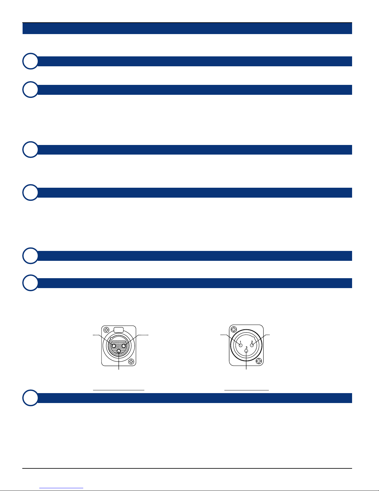
balance controls or headphone mute. For XLR pinout information see the diagram below.
Pin-2
High (+)
Pin-3
Low (-)
Female XLR Pinout Male XLR Pinout
Pin-1
Gnd
(Shield)
Pin-1 Pin-2
Gnd
(Shield)
Pin-3
Low (-)
High (+)
AES Input Balanced XLR Connectors (AES IN 1 and AES IN 2)
These two 3-pin female XLR input connectors (AES IN 1 and AES IN 2) are meant to receive standard AES signals and
are configured for balanced, 110 Ω connections. Note that the unit will monitor these inputs only when the Analog/Digital
Source Select Switch (Item 7, page 8) is set to DIGITAL, and the AES/SDI Digital Source Select Switch (Item 13,
page 10) is set to AES. For XLR pinout information see the diagram under Selected Analog Output Connectors (Item
F).
Note: Do not input signals simultaneously to the XLR and BNC AES input connectors of the same channel (i.e. XLR
connector AES IN 1 and BNC connector AES IN 1).
(Continued)
© 2004 Wohler Technologies Inc. ALL rights reserved
Page 13
AMP2-VSD and AMP2-VSDA User Manual P/N 821581 Rev-B Section 2: Operation
A
B
C D
100-240 VAC
50/60 Hz
AES
IN 1
AES/EBU PORTS
OUT-FROM
AES
1 234
AES
IN 2
OUT-FROM
AES
SDISDI
1 2
OUT
SDI
1
2
IN
ANALOG OUT FROM
DIGITAL SOURCE
3
SELECTED
4
2
CALIB.
HI
LO
HI
LO
HI
LO
HI
LO
TERM 1
GAIN
-180
AMP2-VSDA
253358
LABEL ON SIDE
-9
-20
UNDERWRITERS LABS
SEE POWER SUPPLY
INTERNAL POWER
NUMBER
SERIAL
GAIN CALIB
DIGITAL
+8+6+4
dB
dBFS
-20
AES IN 1
AES IN 2
G H
I
J
100-240 VAC
50/60 Hz
LABEL ON SIDE
A
AES AES
IN 1
AES/EBU PORTS
OUT-FROM
B
SDI
IN 2
AES
TERM 1
1 234
2
CD
OUT-FROM
AES
SDI
CALIB.
GAIN
OUT
SDI
IN
DIGITAL SOURCE
SELECTED
1 2
1
2
ANALOG OUT FROM
3
4
0
-18
-9
HI
LO
HI
LO
HI
LO
HI
LO
AMP2-VSD
253536
UNDERWRITERS LABS
SEE POWER SUPPLY
INTERNAL POWER
NUMBER
SERIAL
+8+6+4
dB
dBFS
-20
-20
AES IN 2AES IN 1
GAIN CALIB
DIGITAL
GH
I
J
123456
4321 65
E
ANALOG IN
SEL. ANALOG OUT
F
CH B (R)CH A (L)
AMP2-VSDA
Figure-2b: Rear Panel Features
© 2004 Wohler Technologies Inc. ALL rights reserved
CH. 1 CH. 2
CH. 3 CH. 4
K
E
F
AMP2-VSD
21
4321 65
534
6
SEL. ANALOG OUT
CH A (L)
CH B (R)
13
Page 14
AMP2-VSD and AMP2-VSDA User Manual P/N 821581 Rev-B
Rear Panel Features
(Continued)
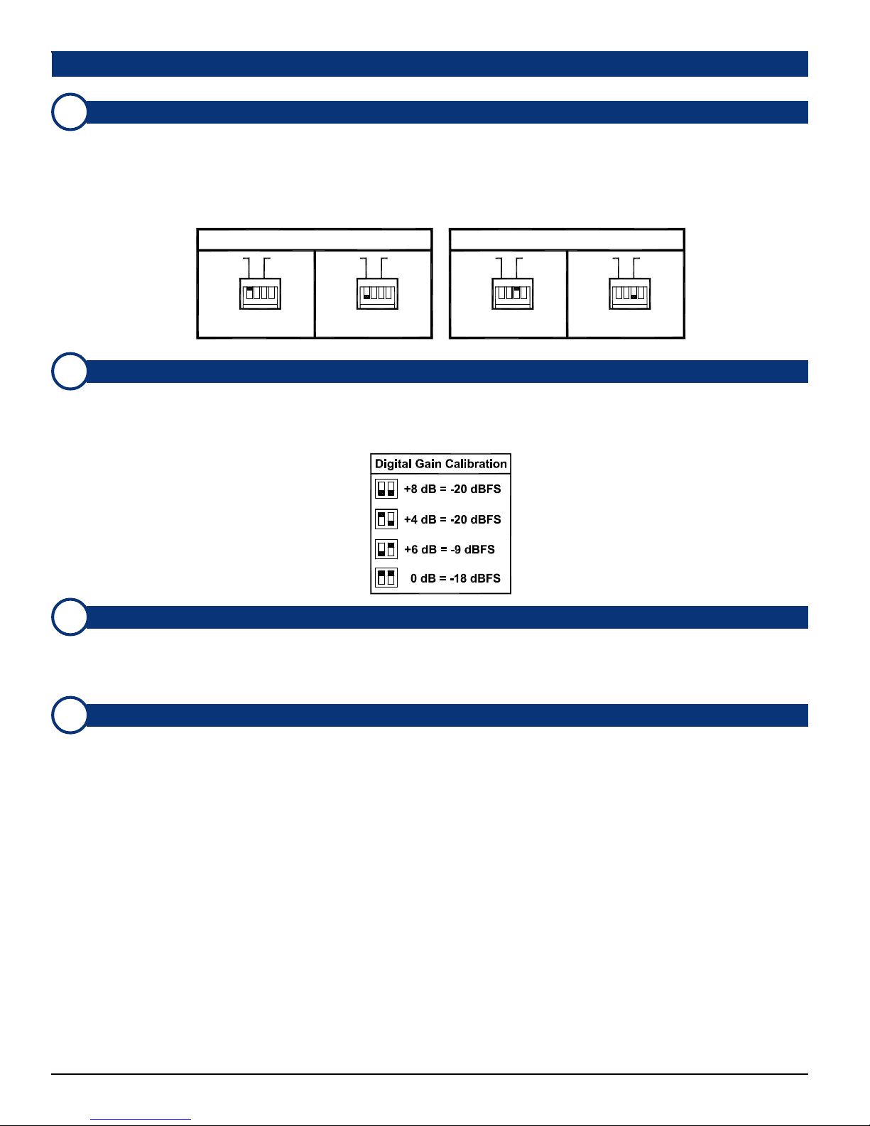
AES Input Termination DIP Switch
H
This 4-position DIP switch module is used to set the termination characteristics for the AES inputs. In the event that either
of the two AES input channels is fed to downstream equipment, the associated DIP switch section (section 1 = AES IN 1
and section 3 = AES IN 2) must be placed in the UP (Unterminated) position. If there is no downstream equipment
connected, then the associated DIP switch section must be placed in the DOWN (Terminated) position. See below for a
diagram of termination settings. Note: Sections 2 and 4 of the DIP module are not used.
Section 2: Operation
AES Input 1 Termination (919050)
Term. 1 Term. 2Term. 1 Term. 2Term. 1 Term. 2Term. 1
Unterminated
AES Input Level Gain Calibration DIP Switch
I
Term. 2
2344
1
IN 1
Note: Positions S2 and S4 of DIP switch are not used.
32
1
IN 1
Terminated
AES Input 2 Termination (919050)
2
41
3
IN 2
Unterminated
1 234
IN 2
Terminated
Input Level Gain Calibration, the analog level which corresponds to a given digital input value, is settable via this DIP
switch. The factory setting is +4 dB (analog) = -20 dBFS (digital). See the silk-screened chart on the rear panel or the
diagram below for settings.
Converted Analog Out Connectors (1-4)
J
These four Phoenix connectors output Analog signals converted from the selected digital inputs (but not the analog
inputs). These ouputs are not affected by the position of the Analog/Digital Source Select Switch (Item 7, page 8).
These 3-pin male Phoenix connectors are configured for a balanced low impedance connection. Phoenix connector pin-out
information is silk-screened just above these connectors on the rear panel (see Figure-2b).
Analog Input Connectors (CH. 1 - CH. 4)
K
These four 3-pin female XLR connectors accept standard analog audio signals and are configured for balanced 70K Ω
connections. For XLR connector pin-out information, see the diagram under Item F on page 12. Note that the Analog
inputs are monitored only when the Analog/Digital Source Select Switch (Item 7, page 8) is set to ANALOG.
14
© 2004 Wohler Technologies Inc. ALL rights reserved
Page 15
AMP2-VSD and AMP2-VSDA User Manual P/N 821581 Rev-B
Section 2: Operation
A
B
C D
100-240 VAC
50/60 Hz
AES
IN 1
AES/EBU PORTS
OUT-FROM
AES
1 234
AES
IN 2
OUT-FROM
AES
SDISDI
1 2
OUT
SDI
1
2
IN
ANALOG OUT FROM
DIGITAL SOURCE
3
SELECTED
4
2
CALIB.
HI
LO
HI
LO
HI
LO
HI
LO
TERM 1
GAIN
-9
-180
AMP2-VSDA
253358
UNDERWRITERS LABS
SEE POWER SUPPLY
INTERNAL POWER
LABEL ON SIDE
NUMBER
SERIAL
+8+6+4
dB
dBFS
-20
-20
AES IN 1
AES IN 2
GAIN CALIB
DIGITAL
G H
I
J
100-240 VAC
50/60 Hz
LABEL ON SIDE
A
AES AES
IN 1
AES/EBU PORTS
OUT-FROM
B
SDI
IN 2
AES
TERM 1
1 234
2
CD
OUT-FROM
AES
SDI
CALIB.
GAIN
OUT
SDI
IN
DIGITAL SOURCE
SELECTED
1 2
1
2
ANALOG OUT FROM
3
4
0
-18
-9
HI
LO
HI
LO
HI
LO
HI
LO
AMP2-VSD
253536
UNDERWRITERS LABS
SEE POWER SUPPLY
INTERNAL POWER
NUMBER
SERIAL
GAIN CALIB
+8+6+4
dB
dBFS
-20
-20
GH
AES IN 2AES IN 1
DIGITAL
I
J
123456
4321 65
E
ANALOG IN
SEL. ANALOG OUT
F
CH B (R)CH A (L)
AMP2-VSDA
Figure-2b: Rear Panel Features
© 2004 Wohler Technologies Inc. ALL rights reserved
CH. 1 CH. 2
CH. 3 CH. 4
K
E
F
AMP2-VSD
21
4321 65
534
6
SEL. ANALOG OUT
CH A (L)
CH B (R)
15
Page 16
AMP2-VSD and AMP2-VSDA User Manual P/N 821581 Rev-B Section 2: Operation
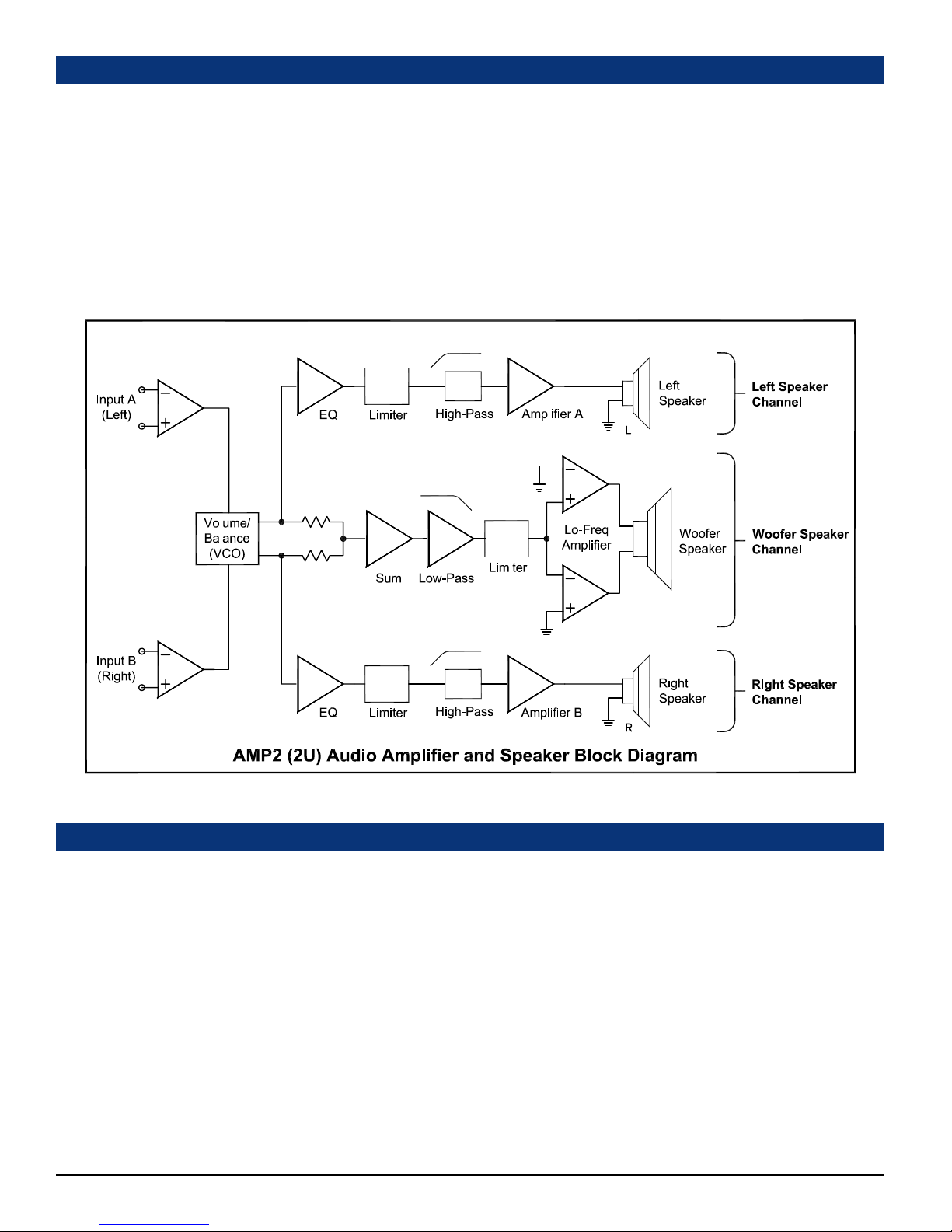
Audio Amplifier and Speaker Configuration
General Description
All models in the AMP Series contain high performance transducers (speakers) driven by three power amplifiers; two amplifier/
driver combinations handle midrange and high frequency information in the left and right (stereo) speaker channels, while the third
amplifier channel sums the left and right channel information below the 500 Hz crossover point in the woofer (bass) speaker(s). Note
that the woofer channel is NOT a dedicated LFE (subwoofer) or Center channel.
Speaker Configuration
All AMP2 (2U) products are configured with two speaker channels (left and right) to reproduce midrange and high-range audio
frequencies (in stereo) and one woofer speaker channel to reproduce the summed (combined) low-range audio frequencies from
the left and right speaker input channels.
See below for a simplified diagram of the AMP2 audio amplifier/speaker configuration.
Balance Control Characteristics
The balance control attenuates the signal from the source, so that the left and right bass frequencies (summed together and
reproduced in the woofer channel) will also respond to the balance control.
Example:
If an audio signal of a voice speaking English is fed to the left (A) input and a voice speaking Spanish is fed to the right
(B) input, then the left speaker channel will reproduce the midrange and high-range frequencies of the English speaking
voice, the right speaker channel will reproduce the midrange and high-range frequencies of the Spanish speaking voice,
and the woofer speaker channel will reproduce the summed (combined) low-range frequencies of both voices.
If the balance control is rotated to the left (English), then the Spanish speaking voice in the right speaker channel will
diminish in volume and the Spanish speaking voice in the woofer speaker channel will also diminish.
Note that if the balance control is rotated completely to the left, the volume in both the left speaker channel and woofer
speaker channel will increase slightly to maintain overall output level. See the simplified diagram below for placement of
the balance control in the audio amplifier circuit.
The converse of the above is true if the balance control is rotated to the right.
16
© 2004 Wohler Technologies Inc. ALL rights reserved
Page 17

AMP2-VSD and AMP2-VSDA User Manual P/N 821581 Rev-B
Section 3
Technical Information
General Technical Observations
SDI to AES Converter Module PCB (919096)
AES to Analog Converter Module PCB (919050)
AES Digital Gain Fine Adjustment (919050)
AES Error Jumper Locations (919050)
Level Meter Rear Panel 6-Position DIP Switch Settings
Level Meter Internal 10-Position DIP Switch Settings
AMP2-VSD Interconnect Block Diagram
AMP2-VSDA Interconnect Block Diagram
© 2004 Wohler Technologies Inc. ALL rights reserved
17
Page 18

AMP2-VSD and AMP2-VSDA User Manual P/N 821581 Rev-B Section 3: Technical Information
General Technical Observations
General Mechanical Observations
Elimination of cabinet and component sympathetic vibrations (resonances) requires considerable attention to mechanical details.
Because of this, and the physical constraints of the speaker’s acoustic enclosures, even minor changes to any of the mechanical
details of the unit can seriously impair its acoustic performance. This especially applies to the speaker baffles. If mechanical
work on the unit is necessary, be sure to make adequate notes to permit accurate reassembly.
Unfortunately, the unusual and wholly proprietary method of magnetic shielding is usually degraded slightly by any disassembly of
the unit, except removal of the rear panel. Almost any maintenance or repair will require removal of the cover. If an immediately
adjacent video monitor shows magnetic interference after reassembly of the unit, it must be returned to the factory to restore the
shielding completely.
General Audio Circuitry Observations
Since a single-sided power supply is used, all amplifier sections are “biased” with a 1/2 supply reference, so all opamp signal
terminals on the main board should have a DC level of +12V, +/-0.7V. Signal inputs to the main audio board from any of the input
select circuits are via the balanced input stage, in lieu of the XLR analog inputs on the basic unit. Signal feed points for level
meters and the phase indicator are immediately after the input stage, and before the volume control section.
The signal pick-off for the headphones is after the volume and balance controls. Speaker muting is controlled by circuitry that
senses connection of headphones to the jack.
The power amps are attached to an aluminum heatsink plate (which is also connected to the circuit common for these devices).
The heatsink plate forms an operational module separate from the chassis, which allows access to the solder side of the circuit
board while power is applied to the circuitry. To avoid thermal shutdown of the power amp(s), they should NOT be operated
without their tabs being fastened to the heatsink plate.
Variations in the frequency response of different production runs of drivers has sometimes required minor adjustments in the
equalization/crossover components in individual runs of units. Some of these components may have values slightly different than
those indicated in the schematic, which are the nominal ones. If any of the drivers (speakers) are replaced, it may be helpful to
change some of these components to achieve maximum flatness of response.
The operating threshold of the woofer limiter is critical to both satisfactory reproduction of musical transients and preventing
damage to, or destruction of, the speaker itself. The side speaker output limiter circuits are similarly important, though not as
critically adjusted.
The woofer power amps are arranged in a bridge configuration; care must be taken to avoid letting EITHER speaker terminal
contact the chassis (common) OR THE GROUNDED LEAD OF ANY TEST EQUIPMENT so as not to short out the power amps.
The side speaker outputs are single-ended, so these precautions are not necessary for them.
18
© 2004 Wohler Technologies Inc. ALL rights reserved
Page 19
AMP2-VSD and AMP2-VSDA User Manual P/N 821581 Rev-B
Section 3: Technical Information
SDI to AES Converter Module PCB (919096)
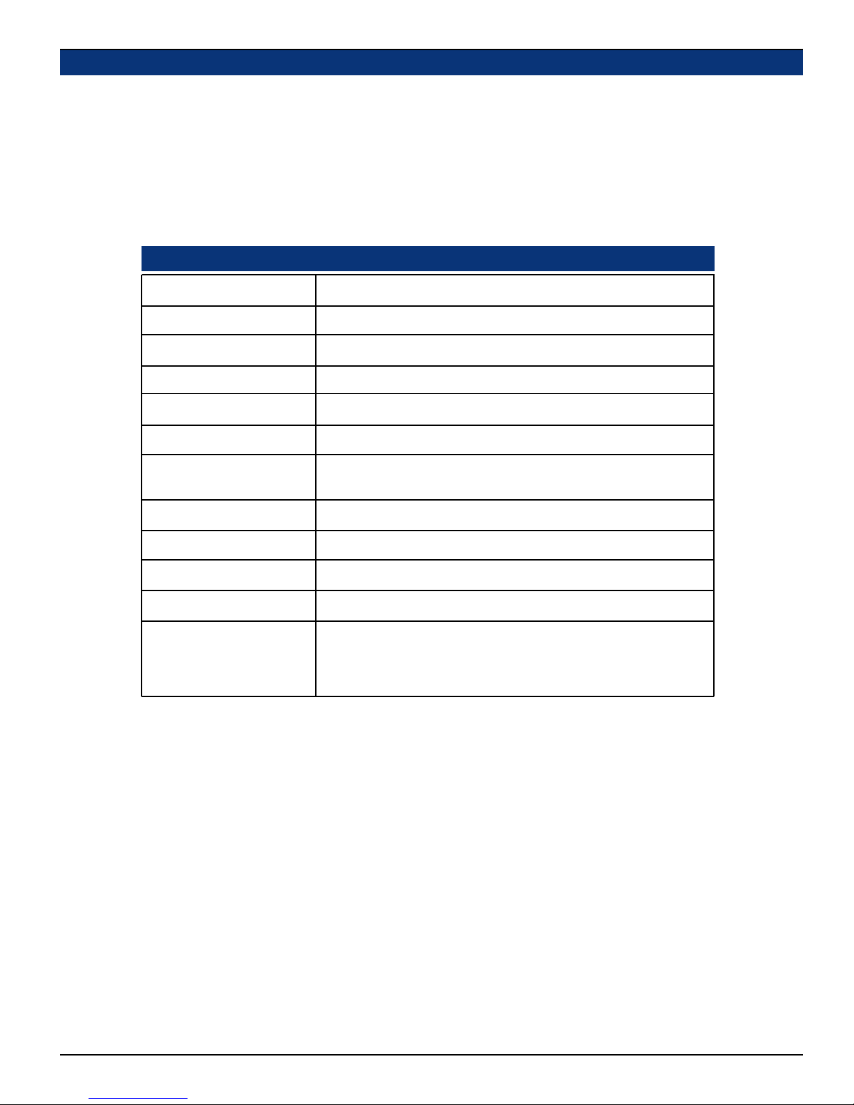
The 919096 (Serial Digital to AES Converter) module allows selected Wohler Technologies audio monitoring systems to be
connected directly to a serial digital video signal containing embedded audio. Two levels of component signals (eg., D1, D5, and
Digi Betacam type) are currently supported; synchronous audio at 48 KHz with either 20-bit data packets or audio and extended data
packets. The 919096 module demultiplexes (extracts) the audio data from the video data, reformatting it to the AES standard. A
companion digital-to-analog converter module (919050) is used to convert the AES signal to analog audio.
In the AMP Digital Series units, channels 1 and 2 (first subgroup) and channels 3 and 4 (second subgroup) from SDI Group ID
#1 are demuxed before being input to the AES to analog conversion module (919050). Access to SDI Group ID #2, #3, and #4
is optional and should be specified at time of order.
919096 Specifications
Input characteristics:
Receiver type:
Sensitivity performance:
SDI input level:
Input formats:
Audio sampling rate:
SDI output type:
SDI output:
SDI output level:
AES from SDI output:
AES data bits:
Error Indication:
75 Ohm (BNC), AC coupled, 15 dB minimum return loss, 10-270 MHz
Auto equalizing with clock regeneration
Tolerates cable loss of at least 30 dB @ 135 MHz
400 - 1000 mV
Component, either 525 or 625 lines w/ 48 KHz audio
48 KHz
Fully regenerated copy of SDI input signal (equalized and regenerated,
scrambled NRZI)
15 dB minimum return loss, risetime 0.75-1.5 ns (20-80%)
800 mV +/-10%
75 Ω BNC
20
Bi-color LED (red/green)
Off = no signal
Green = signal present
Red = Error
© 2004 Wohler Technologies Inc. ALL rights reserved
19
Page 20
AMP2-VSD and AMP2-VSDA User Manual P/N 821581 Rev-B Section 3: Technical Information
AES to Analog Converter Module PCB (919050)
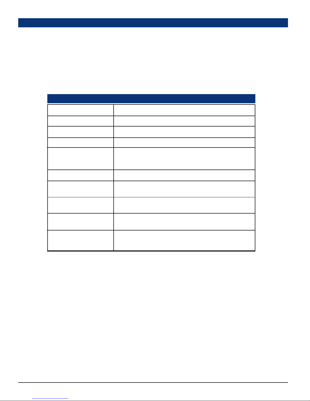
Description
The 919050 Digi-2 (Dual Input AES to Analog Converter) module allows selected Wohler Technologies products to receive
input signals in the AES or SPDIF digital audio data formats. Sampling rate and format selection are sensed and set automatically.
Two front panel mounted bi-color (RED/GREEN) LEDs provide visual indication of input signal status. The LEDs light GREEN
when receiving a valid, error-free data stream, but turn RED when errors are detected. See Item 10 on page 10 for more information
about error detection and indication.
There are two AES inputs, which are configured with unbalanced 75 Ω BNC connectors and balanced 110 Ω XLR connectors. This
module also features a four-channel balanced analog line-level output, which can be configured with unbalanced 75 Ω BNC
connectors or balanced 110 Ω Phoenix or XLR connectors.
919050 Specifications
Input formats:
Digital-to-Analog Conversion:
Sampling rate:
Termination:
Analog out (of digital source),
S/N:
THD (full output):
Max output of analog out:
D to A gain calibration,
(dB = dBFS):
Standard input connectors:
Optional input connectors:
Standard output connectors:
Optional output connectors:
Error Indication:
AES/EBU or SPDIF
24-bit low jitter
31 kHz to 48 kHz
Removable (DIP switch selectable)
Greater than 96 dB
Less than 0.008%
+24 dBv (0 dBv = 0.775 vRMS)
+8 = -20, +4 = -20, +6 = -9, 0 = -18 (DIP switch selectable)
BNC: 75 Ω, unbalanced
Phoenix or XLR: 110 Ω, balanced
BNC: 75 Ω, unbalanced
Phoenix or XLR: 110 Ω, balanced
Two Bi-Color LEDs (on front panel):
Green = OK
Red = Error, no lock to signal, or no signal.
20
© 2004 Wohler Technologies Inc. ALL rights reserved
Page 21
AMP2-VSD and AMP2-VSDA User Manual P/N 821581 Rev-B
Section 3: Technical Information
AES Digital Gain Calibration Fine Adjustment (919050)
The digital gain calibration is set at the factory for +4 dB (Analog) = -20 dBFS (Digital). Three other values (+8 = -20, +6 = -9, and
0 = -18) may also be user selected via a DIP switch on the rear panel (Item I, page 14). However, if a fine adjustment of the
calibration is desired, perform the following procedure:
1) Remove the top cover. Save screws for later reassembly.
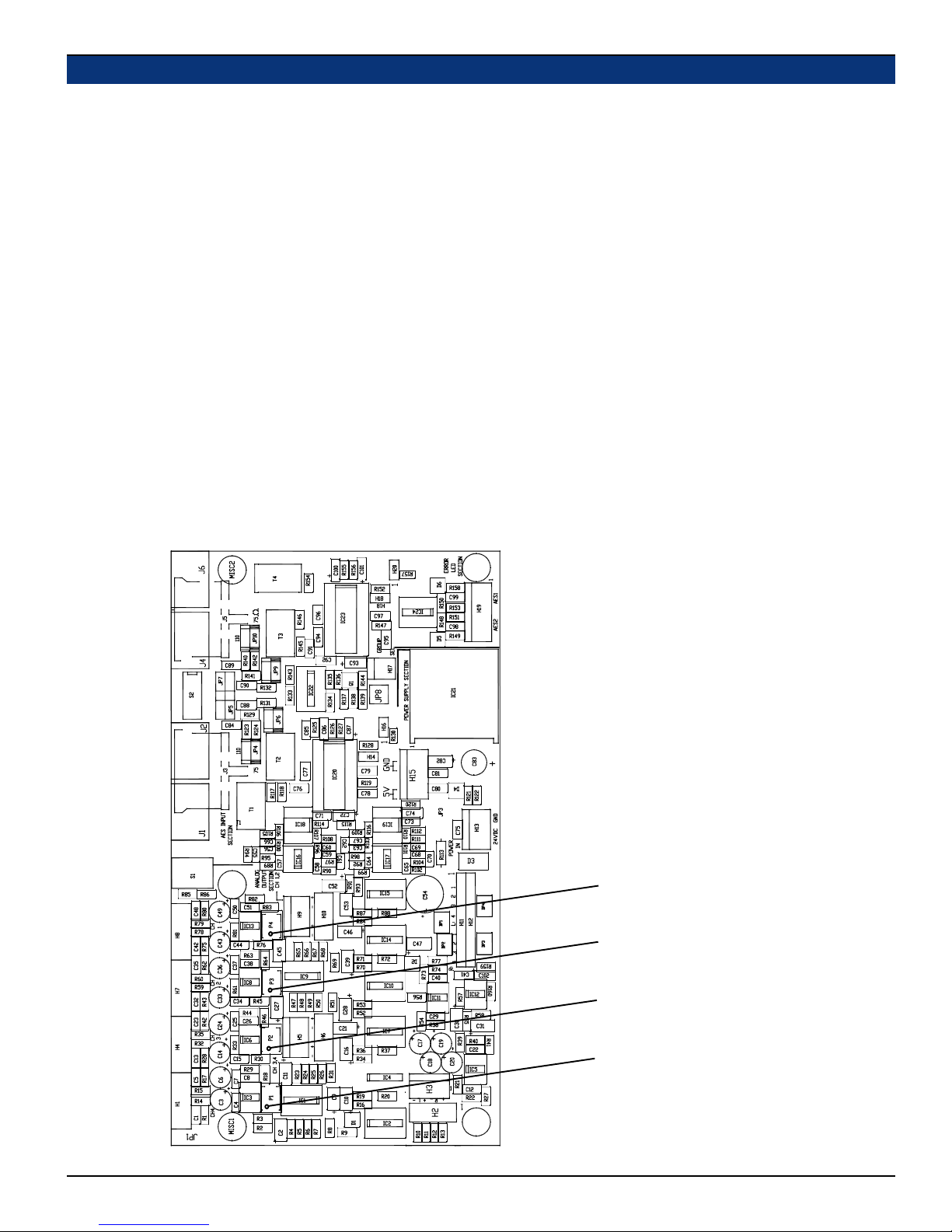
2) You must remove the 919083 PCB to access the trim pots (P1-P4) on the 919050 PCB (see Figure-3a below for trim pot
locations).
3) Connect a digital (AES) source of known digital amplitude and set the unit’s controls to monitor that source. For convenience
sake, it would be best to use your facility’s digital reference level, but any nearby level may be used with appropriate scaling of
output level required.
4) Using an accurate DMM (preferably one having direct reading in dBv/dBu), measure the level on the Converted Analog Output
phoenix connectors (Item J, page 14). Be sure to make measurement of the FULL balanced output, NOT just between one of
the outputs and ground!
5) Locate trim pots P1, P2, P3, and P4 (see Figure-3a below). Adjust P4 (channel 1) through P1 (channel 4) for the desired analog
level corresponding to the digital signal amplitude being supplied to the unit. For example, if your “house” Analog/Digital
correspondence is for a -18 dBfs digital level to correspond to an Analog level of +0dBu, it would be easiest to set the digital source
to -18 dBfs, set the gain calibration DIP switch for -18dBFS = 0dBu and then set P1 through P4 for 0dBu outputs on the phoenix
Analog Output connectors. But, if a digital source of -20dBfs is applied, even though the facility references are for -18dBfs, then
the analog output levels should be adjusted for a -2.0 dBu analog output level on the phoenix connectors.
Note: If the meter being used to measure the analog outputs is not so accurate at those relatively low signal levels, you may wish to
increase the digital signal amplitude by some convenient factor like 10 or even 20 dB. (However, you should not increase above
digital full scale.)
Figure-3a:
AES/EBU to Analog Module PCB (919050)
Digital Gain Calibration Trim Pot Locations
P4 - Adjusts Channel 1
P3 - Adjusts Channel 2
P2 - Adjusts Channel 3
© 2004 Wohler Technologies Inc. ALL rights reserved
P1 - Adjusts Channel 4
21
Page 22
AMP2-VSD and AMP2-VSDA User Manual P/N 821581 Rev-B
AES Error Jumper Locations (919050)
Section 3: Technical Information
To disable indication of faulty
AES data (and leave only indication of faulty reception),
place jumpers on both H14 and
H18. See Item 11, page 10 for
more information.
22
© 2004 Wohler Technologies Inc. ALL rights reserved
Page 23
AMP2-VSD and AMP2-VSDA User Manual P/N 821581 Rev-B Section 3: Technical Information
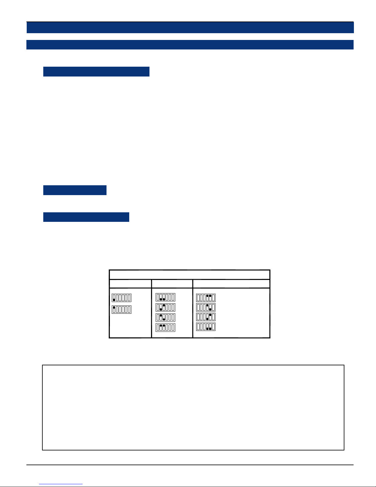
Level Meter Rear Panel 6-Position DIP Switch Settings
Line Level (Auto) Calibration, Reference Level, and Display Mode
This DIP switch sets the Line Level Calibration, Reference Level, and PPM/VU Display Mode. See the descriptions
and diagram below for setting information.
Line Level (Auto) Calibration:
The unit is calibrated at the factory. To recalibrate:
1) Turn on the power.
2) Apply the desired reference level (nominal 0) signal to all channels.
3) Make sure the Reference Level DIP sections (2 and 3) are set to the nearest level of the input signal being applied
for calibration (i.e., 0, +4, +6 or +8). The user should make sure that the signal applied to all four channels is within
+/- 4 dB of the reference level selected by DIP switch sections 2 and 3.
4) Place DIP section 1 in the DOWN position.
5) Wait 10 seconds. The unit will remove the previous calibration and the new calibration will be applied.
6) Place DIP section 1 in the UP position and return unit to service.
7) Only ONE auto-calibration attempt may be made for each cycling of AC power to the unit. Once the Line Level
Calibration DIP switch has been placed in the CAL position, it is necessary to cycle the power before that DIP
switch will be functional again, EVEN if a calibration attempt was unsuccessful.
If one wishes to calibrate again, turn off the power to the unit and repeat steps 1 through 6.
Reference Level:
DIP switch sections 2 and 3 determine the Reference Level, which adjusts the level of the input signal and the
resultant level displayed on the LED bargraphs. Factory setting is +4 dB. See DIP switch diagram below for settings.
Bargraph Display Mode:
DIP switch sections 4 and 5 determine how peak levels are displayed for the associated meters on the front panel.
There are four possible settings; VU Only, VU-PPM Floating Segment, PPM Only, and PPM-PPM Floating
Segment.
The VU Only selection has a VU floating segment when a Peak Hold value is selected using the Internal 10-Position
DIP Switch Module (see page 24). The factory default setting is VU-PPM Floating Segment. See diagam below for
settings.
AMP Series Level Meter Rear Panel DIP Switch Settings
21
Display Mode
x
54
VU Only
VU-PPM
PPM Only
PPM-PPM
534 6
Floating Segment
Floating Segment
Meter Calibration Reference Level
x
2
1
123456
x
Calibrate
Operate
3
+8 dB
+6 dB
+4 dB
0 dB
312 654
Note: Position-6 of DIP switch is NOT used.
See AMP Series Level Meter Internal 10-Position DIP Switch Settings on page 24 for setting the Peak Hold and PPM
Ballistics characteristics.
Meter Calibration NOTE:
For more accurate indication of signal levels, meters are tuned to effect a “rounding” function, which occurs
BETWEEN the thresholds of any two bargraph segments. This means the level meter zero LED segment will turn
on at one-half the smallest spacing between LED segments (mid-scale resolution) before that segment's scale
indication. Below are the offset amounts.
53-Segment Meters: The “rounding offset” is 0.5 dB for the Analog (extended VU), Digital, Nordic, and
DIN scales. It is 0.25 dB for the BBC scale and 0.125 dB for the VU scale.
Example: Using the Analog (extended VU) scale, a meter calibrated for a +4 dBu nominal level will actually
turn the zero LED segment of the level meter on at +3.5 dBu (and so all segments will turn on at 0.5 dBu before
each ones associated silk-screened scale indication).
© 2004 Wohler Technologies Inc. ALL rights reserved
23
Page 24
AMP2-VSD and AMP2-VSDA User Manual P/N 821581 Rev-B
Section 3: Technical Information
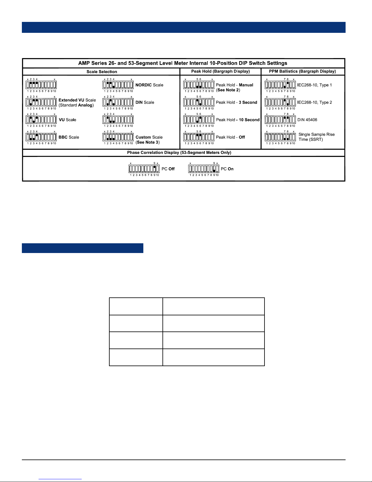
Level Meter Internal 10-Position DIP Switch Settings
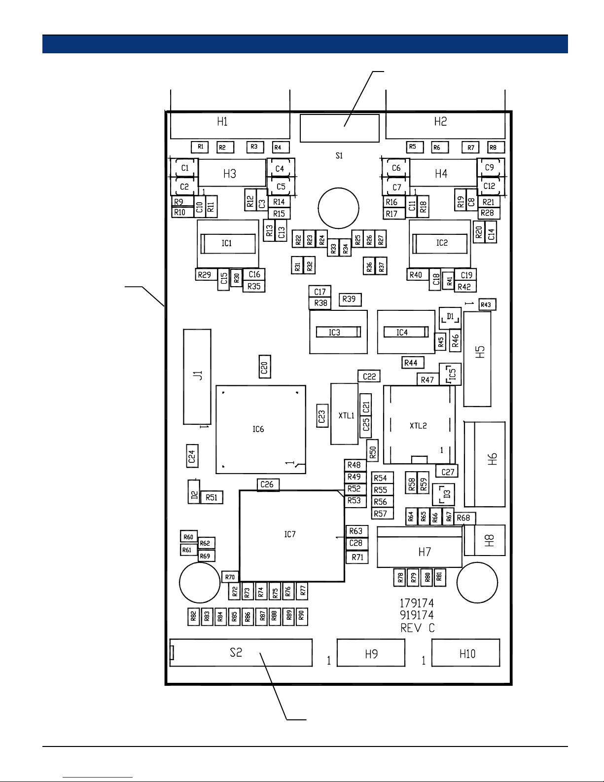
This 10-position DIP switch is accessed by removing the top cover of the AMP unit and is located on the 919174 PCB (the same
PCB on which the 6-position rear panel DIP switch is located). See page 25 for a diagram of the 919174 PCB and the DIP switch
location.
Do Not Use
Do Not Use
NOTES:
1)
Switch positions 1 and 10 are NOT used and should be left at the factory set position.
2)
The Peak Hold - Manual setting allows the bargraph display meters to indefinitely maintain the peak hold value until it is reset by
the operator, either by pressing a reset button (a special option specified at time of order) or by removing power and then
reapplying power to the unit (unplug/replug power cord). Contact Wohler Technologies for more information about this feature.
3)
Contact Wohler Technologies for information about custom scales.
PPPM Characteristics (Ballistics):
The PPM characteristics determine the Integration Time (rise time) and Return Time (fall time) of the level meter. The
Integration Time is the time it takes for the lighted segments of the level meter, after application of a 5 Khz tone at a certain
reference level, to rise within a specified number of dB of that level. Return Time is the time it takes for the lighted segments of
the level meter to fall a certain number of dB after removal of a 5 Khz tone of a certain reference level. The PPM characteristics
available for selection using DIP switch sections 7 and 8 of the 10-position Internal DIP Switch (as shown in the above diagram)
are as follows:
IEC268-10, Type 1:
IEC268-10, Type 2:
DIN 4506:
Single Sample:
Integration (Rise) Time is 5 ms (-2 dB),
Return (Fall) Time is 1.7 seconds (20 dB)
Integration (Rise) Time is 10 ms (-2 dB),
Return (Fall) Time is 2.8 seconds (24 dB)
Integration (Rise) Time is 5 ms (-2 dB),
Return (Fall) Time is 1.5 seconds (20 dB)
Integration (Rise) Time is a single sample,
Return (Fall) Time is 1.5 seconds (20 dB)
24
© 2004 Wohler Technologies Inc. ALL rights reserved
Page 25
AMP2-VSD and AMP2-VSDA User Manual P/N 821581 Rev-B
Level Meter DIP Switch Locations
919174 PCB
Section 3: Technical Information
Level Meter Rear Panel 6-Position
DIP Switch Module
(see page 23)
© 2004 Wohler Technologies Inc. ALL rights reserved
Level Meter Internal 10-Position
DIP Switch Module (see page 24)
25
Page 26
AMP2-VSD and AMP2-VSDA User Manual P/N 821581 Rev-B Section 3: Technical Information
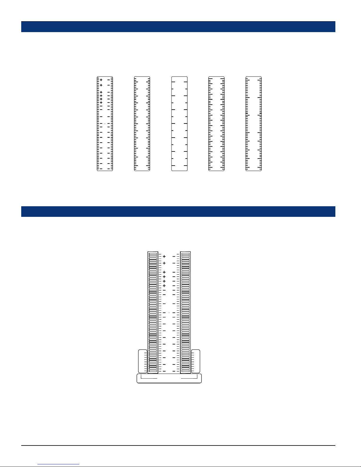
Level Meter Alternative Scales
The standard scale used on the AMP2A-VSD/-VSDA level meters (53-segment) is the Extended VU scale (see diagram below).
However, if alternative scale characteristics are selected for the level meters using the Level Meter Internal 10-Position DIP
Switch (page 24), it is recommended that a label with the appropriate scale be applied to the front panel LED bargraph level meters.
See the diagram below for scale comparison. Scale selection includes the Extended VU (standard Analog), VU, BBC, NORDIC,
DIN, and Custom (not shown) scales. Contact Wohler Technologies for information about alternative scale labels.
0
2
4
7
10
13
16
18
20
22
25
28
31
34
38
42
46
51
56
66
AES
(Digital)
Scale
(standard)
15
12
8
6
4
2
0
2
6
10
12
15
18
22
26
30
35
40
50
Extended VU
(Analog)
Scale
(standard)
+3
+2
+1
0
-1
-2
-3
-5
-7
-10
-15
-20
VU
Scale
7
6
5
4
3
2
1
BBC
Scale
+12
+9
+6
+3
T
-3
-6
-9
-12
-15
-18
-21
-24
-27
-30
-33
-36
-42
NORDIC
Scale
+5
0
-5
-10
-20
-30
-40
-50
DIN
Scale
Level Meter Phase Correlation Feature
Since it is sometimes helpful to observe phase relationships between two signals being monitored, a Phase Correlation
feature can be implemented within the lower section of an existing bargraph pair in the 53-segment LED bargraph level
meters used in the AMP2 units. This feature may be turned ON and OFF by setting the Level Meter Internal 10-Position
DIP Swich module (page 24). Below is an illustration of the level meter bargraphs with the Phase Correlation label applied.
15
12
8
6
4
2
0
2
6
10
12
15
18
22
26
-1
.5
0
30
35
40
50
correlation
+1
.5
0
When the audio level in BOTH channels is high enough, the Phase Correlation display occupies the lower few segments of
both bargraphs of a stereo pair. Behavior of the Phase Correlation indication is as follows:
Positive correlation = ascending AMBER bar in the right bargraph
Negative correlation = ascending RED bar in the left bargraph
The bottom nine (9) segments are used by the 53-segment LED bargraph display for Phase Correlation indication. One
additional segment above the active correlation region is always OFF, to serve as a marker. The Phase Correlation display
is visible ONLY so long as the VU audio level is above this blank segment (tenth from the bottom).
26
© 2004 Wohler Technologies Inc. ALL rights reserved
Page 27
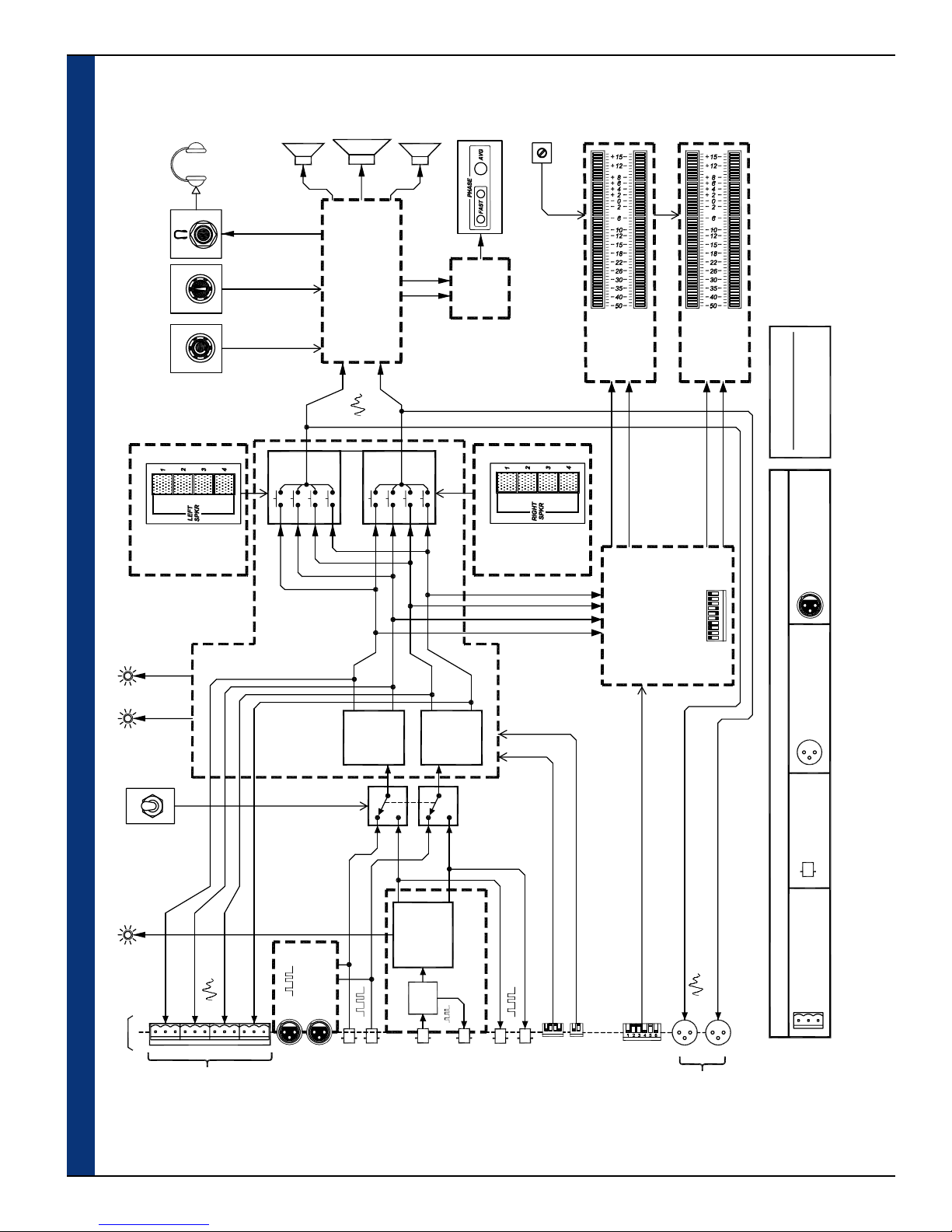
AMP2-VSD and AMP2-VSDA User Manual P/N 821581 Rev-B Section 3: Technical Information
Volume Balance
919202 PCB
LEFT
Headphone
Select
Source
Speaker
1
Channel
Left
L
2
Woofer
Channel
Speaker
Audio Amplifier PCB
L
Left
4
3
Speaker
919209-2
R
1
2
Right
Right
3
Channel
Speaker
R
4
Phase
Phase
Indication
Indication
Bargraph
PCB
919084
919202 PCB
RIGHT
brightness
Disply
Select
Source
Speaker
Adjust
53-Segment
Level Meters
1
53-Seg
Bargraph
CH.2
CH.1
1-2
243
919190
Driver PCB
53-Segment
3-4
Level Meters
53-Seg
Bargraph
Driver PCB
CH.3
CH.4
919190
(Rev-A, 06/30/04)
Balanced
Ω,
Unbalanced
Ω,
XLR-F = 110
Digital Input Impedances:
BNC = 75
AES 2
AES
LEDs
Status
AES 1
SDI
AES
AMP2-VSD Interconnect Block Diagram
SDI
Status LED
Rear
Panel
1
3
2
4
919050
Converter
Dual Input
AES to Analog
919111
AES BAL. IN
D/A 1
Converter
AES
SDI
D/A 2
Converter
SDI
AES
Converter
SDI to AES
Re-
Clock
Digital Input
Source Select
919096
SDI/AES Converter
8 91023 75641
(919174)
Level Meter
Alt. Scales,Peak Hold,
Correlation DIP Switch
Analog Input, 4-Channel
Level Meter Engine PCB
PPM Ballistics and Phase
= XLR-M, 3-Pin, Male = XLR-F, 3-Pin, Fem.
Connector Legend
AMP2-VSD Interconnect Block Diagram
= BNC, Female
Chan. B (Right)
Chan. A (Left)
3412
21
= Phoenix, 3-Pin, Male
1-4
OUT
ANALOG
CONVERTED
© 2004 Wohler Technologies Inc. ALL rights reserved
AES IN 1
AES IN 1
AES IN 2
AES IN 2
SDI IN
SDI OUT
AES Term
(From-SDI)
AES OUT 1
AES OUT 2
DIP Switch
DIP Switch
AES Gain Calib.
L-R
OUTPUT
SELECTED
Mode, Auto-Calib. DIP Switch
Level Meter Ref. Level, Display
27
Page 28
AMP2-VSD and AMP2-VSDA User Manual P/N 821581 Rev-B
Section 3: Technical Information
Volume Balance
919202 PCB
LEFT
Headphone
Select
Source
Speaker
1
Channel
Left
L
2
Woofer
Channel
Speaker
Audio Amplifier PCB
L
Left
4
3
Speaker
919209-2
R
1
2
Right
Right
3
Channel
Speaker
R
4
Phase
Phase
Indication
Indication
PCB
919084
919202 PCB
RIGHT
Bargraph
Disply
Source
Speaker
Adjust
brightness
Select
53-Segment
Level Meters
1
53-Seg
Bargraph
CH.2
CH.1
1-2
243
919190
Driver PCB
53-Segment
3-4
Level Meters
53-Seg
Bargraph
Driver PCB
CH.3
CH.4
8 91023 75641
919190
(Rev-A, 06/28/04)
Balanced
Balanced
Ω,
Ω,
Unbalanced
Ω,
Analog Input Impedances:
XLR-F = 70K
XLR-F = 110
Digital Input Impedances:
BNC = 75
Analog/
Source
Digital
ANALOG
AES 2
AES 1
AES
Select
DIGITAL
LEDs
Status
919050
Converter
Dual Input
AES to Analog
A
1
1
2
DAD
2
D/A 1
Converter
4
3
ADD
A
4
3
D/A 2
Converter
AMP2-VSDA Interconnect Block Diagram
SDI
AES
SDI
SDI
AES
Converter
SDI to AES
Re-
Clock
SDI IN
Digital Input
SDI/AES Converter
SDI OUT
28
SDI
Status LED
Rear
Panel
1
CONVERTED
2
ANALOG
3
OUT
1-4
AES
919111
AES BAL. IN
4
AES IN 1
AES IN 1
AES IN 2
AES IN 2
© 2004 Wohler Technologies Inc. ALL rights reserved
919083
Plugin Module
2/4 Switch PCB
Source Select
919096
(From-SDI)
AES OUT 1
AES OUT 2
3412
AES Term
DIP Switch
AES Gain Calib.
(919174)
Analog Input, 4-Channel
Level Meter Engine PCB
21
1
DIP Switch
Mode, Auto-Calib. DIP Switch
Level Meter Ref. Level, Display
Level Meter
Alt. Scales,Peak Hold,
Correlation DIP Switch
PPM Ballistics and Phase
2
3
1-4
INPUT
ANALOG
4
Connector Legend
Chan. B (Right)
Chan. A (Left)
L-R
OUTPUT
SELECTED
= XLR-M, 3-Pin, Male = XLR-F, 3-Pin, Fem.
= BNC, Female
AMP2-VSDA Interconnect Block Diagram
= Phoenix, 3-Pin, Male
Page 29

AMP2-VSD and AMP2-VSDA User Manual P/N 821581 Rev-B
NOTE:
PCB layout and schematic support documentation is available upon request.
© 2004 Wohler Technologies Inc. ALL rights reserved
29
Page 30
AMP2-VSD and AMP2-VSDA User Manual P/N 821581 Rev-B
Wohler Technologies, Inc.
Wohler Technologies, Inc.
1-888-596-4537 Fax: (510) 870-0811
Phone: (510) 870-0810 Fax: (510) 870-0811
31055 Huntwood Avenue
31055 Huntwood Avenue
Hayward, CA 94544
Hayward, CA 94544
web: www.wohler.com
US Toll-Free: 1-888-596-4537
e-mail: [email protected]
www.wohler.com [email protected]
30
© 2004 Wohler Technologies Inc. ALL rights reserved
 Loading...