

Page 1

AMPx-S8 Series
• AMP1-S8DA • AMP1-S8MDA-3G
• AMP2-S8DA • AMP2-S8MDA-3G
8-Channel, Multi-Format, Analog/Digital
Audio Monitors
User Guide
Part Number 821030, Revision E
Page 2

© 2011 Wohler Technologies, Inc. All rights reserved.
This publication is protected by federal copyright law. No part of this publication may be
copied or distributed, stored in a retrieval system, or translated into any human or computer
language in any form or by any means electronic, mechanical, manual, magnetic, or otherwise,
or disclosed to third parties without the express written permission of Wohler Technologies.
Reproduction
Licensed users and authorized distributors of Wohler Technologies, Inc. products may copy
this document for use with Wohler Technologies., Inc. products provided that the copyright
notice above is included in all reproductions.
Customer Support
Wohler Technologies, Inc.
31055 Huntwood Avenue
Hayward, CA 94544
www.wohler.com
Phone: 510-870-0810
FAX: 510-870-0811
US Toll Free: 1-888-596-4537
(1-888-5-WOHLER)
Web: www.wohler.com
Sales: [email protected]
Support: [email protected]
Disclaimers
Even though Wohler Technologies, Inc. has tested its equipment and software, and reviewed
the documentation, Wohler Technologies, Inc. makes no warranty or representation, either
express or implied, with respect to software, documentation, their quality, performance,
merchantability, or fitness for a particular purpose.
Wohler Technologies, Inc. reserves the right to change or improve our products at any time and
without notice.
In no event will Wohler Technologies, Inc. be liable for direct, indirect, special, incidental, or
consequential damages resulting from any defect in the hardware, software, or its
documentation, even if advised of the possibility of such damages.
Some states do not allow the exclusion or limitation for incidental or consequential damages, so
the above exclusion or limitation may not apply to you.
Printing
This document is intended to be printed on a duplex printer, such that the copy appears on
both sides of each page. This ensures that all new chapters start on a right-facing page.
This document looks best when printed on a color printer since some images may be indistinct
when printed on a black and white printer.
Other Technologies and Products
Microsoft Windows, and Internet Explorer are registered trademarks of Microsoft Corporation.
The Tascam trademark is owned by Teac, Inc.
Last Update
June 06, 2011
821030: AMPx-S8 Series User Guide
ii
© 2011 Wohler Technologies, Inc. All rights reserved.
Page 3

Table of Contents
Preface . . . . . . . . . . . . . . . . . . . . . . . . . . . . . . . . . . . . . . . vii
Introduction ................................................................. vii
Overview................................................................ vii
Topics.................................................................... vii
What’s New................................................................. viii
Functionality Enhancements .......................................... viii
3G........................................................................ viii
Software Termination.............................................. viii
Rear Panel Connector Arrangements ...........................ix
Chapter 1. Installation . . . . . . . . . . . . . . . . . . . . . . . . . . . .1
Introduction ...................................................................1
Overview..................................................................1
Topics......................................................................1
Unpacking......................................................................2
Safety ...........................................................................2
Important Safety Instructions ..................................... 2
Safety Symbols.........................................................3
FCC Compliance..............................................................3
Installation Recommendations...........................................4
Mounting..................................................................4
Heat Dissipation........................................................4
Sympathetic Vibration................................................4
Mechanical Bracing....................................................5
Connections and Cable Recommendations.....................5
Electrical Interference ................................................5
Power ......................................................................6
821030: AMPx-S8 Series User Guide
© 2011 Wohler Technologies, Inc. All rights reserved.
iii
Page 4

Installation.................................................................... 6
Intial Setup.............................................................. 6
Power Up................................................................. 6
Chapter 2. System Overview . . . . . . . . . . . . . . . . . . . . . . . 7
Introduction................................................................... 7
Overview................................................................. 7
Topics ..................................................................... 7
Front Panel Controls........................................................ 8
Features and Simple Controls..................................... 8
LCD Screen.............................................................10
User Interface.........................................................11
Multi-Mode Color Codes ......................................11
Menu Navigation................................................12
Rear Panel Connectors ...................................................13
Input Connectors.....................................................13
Output Connectors...................................................15
Programming and Remote Access Connectors..............18
RS-232 Connectors ............................................18
Remote Connector .............................................18
Rotary Switch Connectors.........................................19
Monitoring Inputs..........................................................20
System Overview.....................................................20
Monitoring an Analog Input.......................................20
Monitoring an AES Input...........................................21
Monitoring an SDI Input ...........................................21
Channel Selection and Mixing .........................................22
Chapter 3. Audio Configuration . . . . . . . . . . . . . . . . . . . . 23
Introduction..................................................................23
Overview................................................................23
Topics ....................................................................23
821030: AMPx-S8 Series User Guide
iv
© 2011 Wohler Technologies, Inc. All rights reserved.
Page 5

Analog Output Preference...............................................24
Monitoring and Mixing Modes..........................................25
Arbtrary Mixing .......................................................25
Single....................................................................26
Pairs......................................................................26
Downmix................................................................27
Muting the Speakers......................................................29
Phase Correlation..........................................................30
SDI Inputs ...................................................................31
Selecting SDI Groups and Subgroups .........................31
Configuring for SDI Delay ........................................32
Selecting the Input Signal ..............................................33
Setting the Monitor’s Startup Configuration.......................34
Terminating/Unterminating Inputs ...................................35
Chapter 4. Presets. . . . . . . . . . . . . . . . . . . . . . . . . . . . . . .37
Introduction .................................................................37
Overview................................................................37
Topics....................................................................37
What are Presets? .........................................................38
Methods of Accessing the Presets ....................................38
Setup Menu............................................................38
Preset Mode............................................................38
Enabling/Disabling Preset Mode ...........................39
Recalling a Preset ..............................................39
Speaker Assign/Preset Buttons
(Presets 1 through 4 Only) .......................................39
Saving a Preset .................................................40
Recalling a Preset ..............................................40
Overwriting a Preset ..........................................40
821030: AMPx-S8 Series User Guide
© 2011 Wohler Technologies, Inc. All rights reserved.
v
Page 6

Chapter 5. Setup Menu . . . . . . . . . . . . . . . . . . . . . . . . . . . 43
Introduction..................................................................43
Overview................................................................43
Topics ....................................................................43
Accessing Setup Mode....................................................44
Analog Output Preference Mode.......................................46
Recalling a Preset..........................................................46
Saving a Preset.............................................................47
Creating a New Preset .............................................48
Overwriting an Existing Preset...................................49
Preset Mode..................................................................51
Erasing a Preset ............................................................51
SDI Delay.....................................................................52
Startup ........................................................................53
Surround Gain ..............................................................53
Bitstream Detection.......................................................54
Phase Bits ....................................................................55
Chapter 6. Features and Specifications . . . . . . . . . . . . . . 57
Introduction..................................................................57
Overview................................................................57
Topics ....................................................................57
Features.......................................................................58
Common Features....................................................58
Model Dinstinctions..................................................58
Specifications................................................................59
Technical Functional Overview.........................................60
821030: AMPx-S8 Series User Guide
vi
© 2011 Wohler Technologies, Inc. All rights reserved.
Page 7

Introduction
Overview
The preface lists the new features and functionality for this release.
Topics
Topics Page
What’s New viii
Preface
Functionality Enhancements viii
821030: AMPx-S8 Series User Guide
© 2011 Wohler Technologies, Inc. All rights reserved.
vii
Page 8
Preface
What’s New
What’s New
This release provides several changes and functionality enhancements:
• 3G functionality (now available in 1RU!)
• Signal termination moved to software control
• Bitstream Detection on page 54
• Phase Bits on page 55
Functionality Enhancements
3G
In adding the 3G functionality, we have also discontinued the MDA
models as shown in the following table:
Old Version
AMP1-S8MDA AMP1-S8MDA-3G
AMP2-S8MDA AMP2-S8MDA-3G
Moreover, we are replacing some similar products as well that may also
include other changes.
Old Version
AMP1-S8DA (PN 8101-0030) AMP1-S8DA (PN 8101-0110)
AMP2-S8DA (PN 8103-0020) AMP2-S8DA (PN 8102-0060)
Software Termination
New Version Replacement
Suggestions
New Version Replacement
Suggestions
In this release, all terminations are no longer on the rear panel; they are
now controlled by the software. Refer to Terminating/Unterminating
Inputs on page 35 for details.
821030: AMPx-S8 Series User Guide
viii
© 2011 Wohler Technologies, Inc. All rights reserved.
Page 9

Functionality Enhancements
Rear Panel Connector Arrangements
Note that in the process of redesigning the AMPx-S8 Series monitors,
we have rearranged the rear panels. Refer to Appendix A on page 67
for remapping information.
Preface
821030: AMPx-S8 Series User Guide
© 2011 Wohler Technologies, Inc. All rights reserved.
ix
Page 10

Page 11

Introduction
Overview
This chapter describes the front panel controls and the rear panel
connectors in detail. It also describes how to use the front panel user
interface for data display and system configuration. Configuration
procedures are covered in detail in Chapter 3 on page 23.
CHAPTER 1
Installation
Topics
Topics Page
Introduction 1
Unpacking 2
Safety 2
FCC Compliance 3
Installation Recommendations 4
Installation 6
821030: AMPx-S8 Series User Guide
© 2011 Wohler Technologies, Inc. All rights reserved.
1
Page 12

Chapter 1 Installation
Unpacking
Unpacking
Unpack the AMPx-S8 Series monitor and inspect for any apparent physical
damage that may have occurred in transit. If the unit has been damaged,
contact Wohler customer support for assistance. (Wohler’s contact
information is on page ii of this document.)
In addition to the monitor, the package should contain:
• A CDROM containing the product’s user guide,
• A power cord, and
• A warranty card
Note:
We recommend you retain the shipping carton for future
use.
Safety
Important Safety Instructions
1. Read, keep, and follow all of these instructions; heed all warnings.
2. Do not use this equipment near water, rain or moisture.
3. Use only a dry cloth to clean the equipment.
4. Do not block any ventilation openings. Install only in accordance
with the instructions in Installation Recommendations on page 4.
5. Do not install near any heat source such as a radiator, heat register,
amplifier, or stove.
6. Do not attempt to plug the unit into a two-blade outlet (with only
two prongs of equal width).
IMPORTANT:
821030: AMPx-S8 Series User Guide
2
© 2011 Wohler Technologies, Inc. All rights reserved.
By design, these monitors will only plug into a three-prong outlet for
your safety. If the plug does not fit into your outlet, contact an
electrician to replace the obsolete outlet.
Page 13
Chapter 1 Installation
FCC Compliance
7. Protect the power cord from being walked on or pinched,
particularly at plug’s source on the equipment and at the socket.
8. Use only the attachments/accessories specified by the
manufacturer.
9. Unplug the equipment during lightning storms or when unused
for long periods of time.
10. Use of a cart is neither recommended nor approved by Wohler.
11. Refer all servicing to qualified service personnel. Servicing will be
required under all of the following conditions:
• The equipment has been damaged in any way, such as when
the power-supply cord or plug is damaged.
• Objects have fallen onto the equipment; or the equipment has
been exposed to rain or moisture, or liquid has been spilled
onto the equipment.
• The equipment does not operate normally.
• The equipment has been dropped.
Safety Symbols
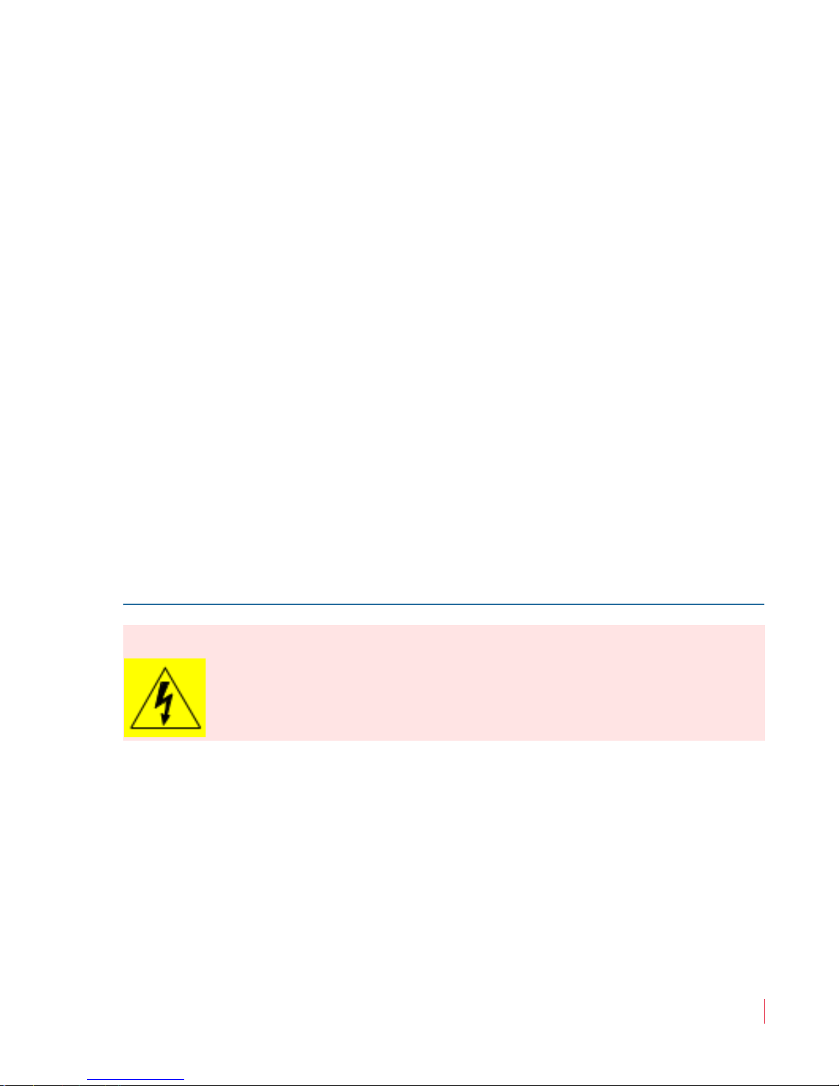
WARNING:
The symbol to the left warns of electric shock hazard inside the unit.
Disconnect the power cord before removing access panels when
installing upgrades. Only qualified service personnel are to operate the
equipment with covers removed, and are to exercise caution to avoid
personal injury.
FCC Compliance
This equipment has been tested and found to comply with the limits for
a Class A digital device, pursuant to part 15 of the FCC Rules. These
limits are designed to provide reasonable protection against harmful
interference when the equipment is operated in a commercial
environment. This equipment generates, uses, and can radiate radio
frequency energy and, if not installed and used in accordance with the
821030: AMPx-S8 Series User Guide
© 2011 Wohler Technologies, Inc. All rights reserved.
3
Page 14
Chapter 1 Installation
Installation Recommendations
instruction manual, may cause harmful interference to radio
communications. Operation of this equipment in a residential area is
likely to cause harmful interference in which case the user will be
required to correct the interference at his own expense.
Installation Recommendations
Mounting
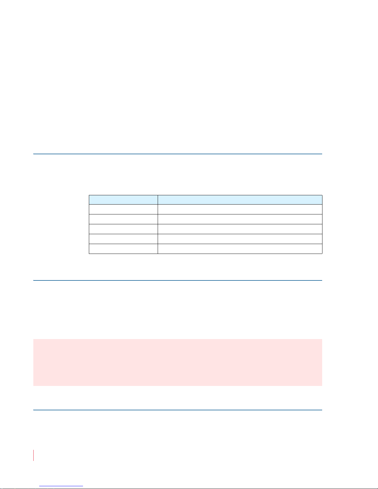
The unit is designed to install into a standard 19" rack mounted at ear
level for best high frequency response and visual observation of the
monitor screen. Please adhere to the following clearances:
Clearance Surface
24” Front
3” Rear
2” Sides
1.75” Top and Bottom (if either radiates heat)
0” Top and Bottom (if no heat)
Heat Dissipation
The ambient temperature inside the mounting enclosure should not
exceed 40° Celsius (104° Fahrenheit). Adjacent devices can be rack
mounted (or stacked) in proximity to the unit if this temperature is not
exceeded. Otherwise, allow a 1RU (1.75”/44.45mm) space above and
below the unit for air circulation.
Important:
To reduce noise, the monitor does not have any fans. As a result, the
heat generated by the class D power amplifiers, power supplies, and
other components is vented by slots in the side of the unit. Therefore,
as a safety precaution, you must allow proper ventilation on both sides
of the unit.
Sympathetic Vibration
Sympathetic vibration from other equipment (cables, etc.,) in the rack
may be serious enough to interfere with the unit’s sound quality. The
821030: AMPx-S8 Series User Guide
4
© 2011 Wohler Technologies, Inc. All rights reserved.
Page 15
Chapter 1 Installation
Installation Recommendations
use of thin card stock and/or felt or foam weather-stripping type
materials between adjacent vibrating surfaces, or tying up loose cables,
etc., may be required to stop vibrations external to the unit.
Mechanical Bracing
Even though the 2U models are fairly heavy, the chassis is securely
attached to the front panel. In addition, the chassis has mounting tabs
through which you attach it to the rack rail. This feature will reduce or
eliminate rear bracing requirements in many mobile/portable
applications. The weight of internal components is distributed fairly
evenly around the unit.
Connections and Cable Recommendations
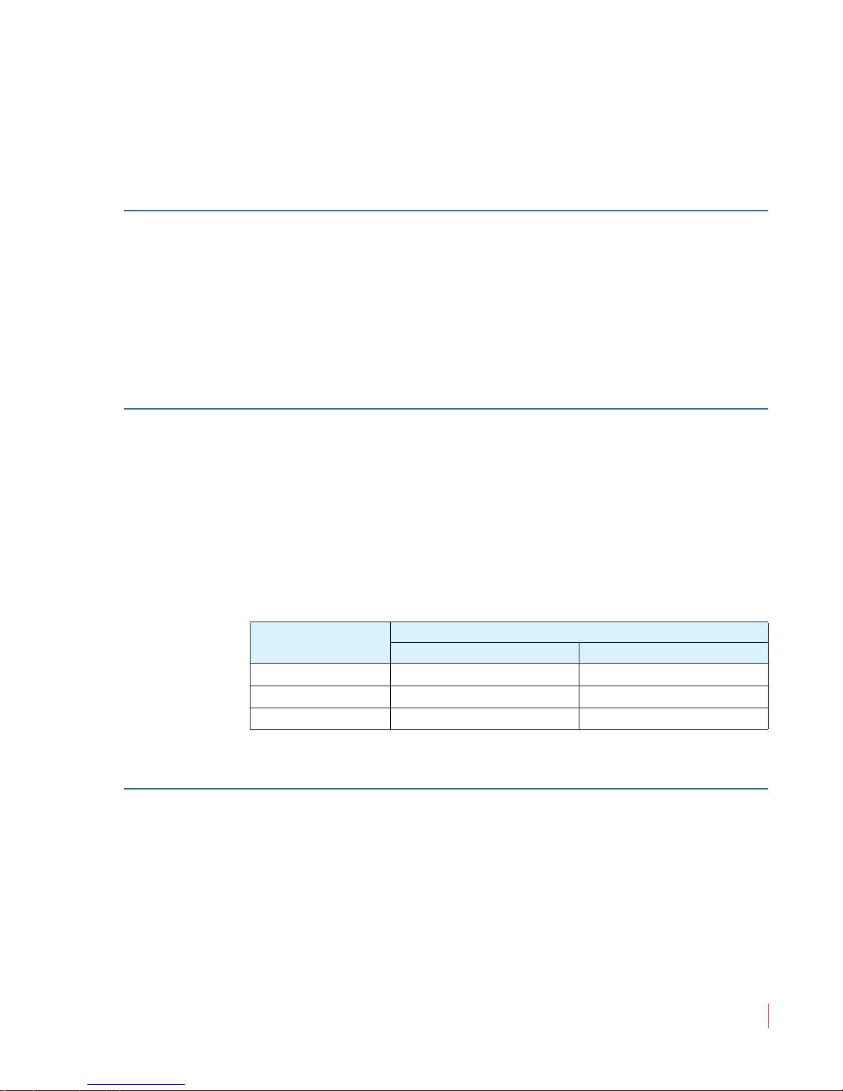
We recommend that you limit the length of the cables that you use for
feeding HD-SDI signals sources to the HD-SDI inputs of the AMPx-E8
Series units and that you use a Belden 1694A cable (or equivalent).
Note:
The connections of all DB-25 connectors are compatible with
Tascam DB-25 to XLR cable assemblies. Consult the factory
for availability. All rear panel connectors are female except
for the XLR connectors.
Table 1–1 Cable Length Limit Recommendations
Signal Type
SD 300 984
HD 150 492
3G 22 75
Electrical Interference
Be careful to apply proper input termination settings and avoid
mismatched cable types and other similar causes of undesired
reflections in digital signal systems. If severe enough, such reflections
can result in corruption of the digital data stream. As with any audio
equipment, maximum immunity from electrical interference requires
the use of shielded cable; however, satisfactory results can sometimes
be obtained without it. The internal circuitry ground is connected to the
chassis.
Maximum Length
Meters Feet
821030: AMPx-S8 Series User Guide
© 2011 Wohler Technologies, Inc. All rights reserved.
5
Page 16

Chapter 1 Installation
Installation
Power
The unit comes with a standard 24VDC/3.0 A internal power supply
and connects an A/C mains power source (65W, 100 to 240 VAC, 50/
60Hz) through the IEC connector provided on the rear panel of the unit.
When the mains plug or appliance coupler is used as the disconnect
device, the disconnect device should remain operable.
Installation
Intial Setup
Power Up
1. Carefully install the monitor into a standard 19”-rack.
2. Connect all signal cables to and from associated equipment.
3. Connect the power cord from the monitor to A/C mains.
The AMPx-S8 Series monitors are factory-configured so that all settings
are non-volatile. When power to the unit is cycled (off/on), the unit will
restore itself so that each setting such as channel selection(s), input
type, and so on, are automatically restored to the unit’s previous
factory setting. However, you can custom configure the monitor to
automatically restore your configuration settings on power up. Refer to
Setup Menu on page 43 for details.
821030: AMPx-S8 Series User Guide
6
© 2011 Wohler Technologies, Inc. All rights reserved.
Page 17

Introduction
Overview
This chapter describes how to install the AMPx-S8 Series monitor into a
standard 19”-rack and how to connect the audio cables.
Topics
CHAPTER 2
System Overview
Topics Page
Introduction 7
Front Panel Controls 8
Rear Panel Connectors 13
Monitoring Inputs 20
Channel Selection and Mixing 22
821030: AMPx-S8 Series User Guide
© 2011 Wohler Technologies, Inc. All rights reserved.
7
Page 18

Chapter 2 System Overview
Front Panel Controls
Front Panel Controls
Features and Simple Controls
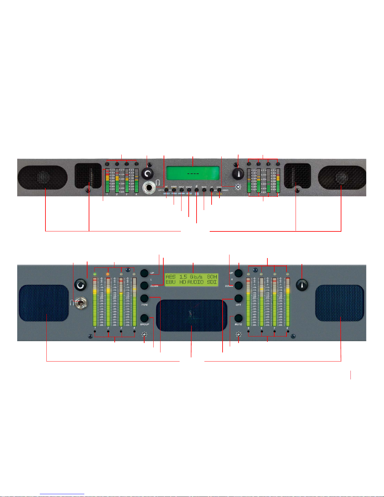
Refer to the images in Figure 2–1 and Figure 2–2 on the next page.
In addition, on the AMP1s, the top LED segment of each bar graph
serves as the speaker assign LED for the respective channel.
• Speakers: The AMP2s features two mid-range speakers (left and
right) and one woofer speaker. The AMP1s have two woofers. All
models of the AMPx-S8 Series contain high performance
transducers driven by three power amplifiers. Two amplifier/
driver combinations handle midrange and high frequency
information in the left and right (stereo) speaker channels, while the
third channel reproduces and sums the left and right channel
information below the crossover point in the woofer (bass) speaker.
Note that the woofer channel is not a dedicated LFE (sub-woofer) or
center channel.
• Level Meters (1 through 8): Source channels 1 through 8 are
displayed through eight audio level meters, four on the left side;
four on the right side. These level meters, high-resolution LED bar
graph displays and feature a dynamic range of 66 dB with PPM dot
over VU bar ballistic characteristics.
• Headphones (1/4” Jack): Select the headphone audio sources as
you would for the internal speakers. When you plug in headphones
the speakers will mute.
• Volume (Rotary Knob): This control adjusts the loudness of the
audio reproduced by the internal speaker channels or connected
headphones.
• Balance (Rotary Knob): This control adjusts the volume balance
between the left and right speaker channels. Note that this control
attenuates the signal from the source, so that the left and right bass
frequencies (summed together and reproduced in the woofer
channel) will respond to balance adjustments in tandem with the
left and right speaker channels.
821030: AMPx-S8 Series User Guide
8
© 2011 Wohler Technologies, Inc. All rights reserved.
Page 19
821030: AMPx-S8 Series User Guide
© 2011 Wohler Technologies, Inc. All rights reserved.
9
Chapter 2 System Overview
Front Panel Controls
Figure 2–1 The AMP1-S8 Series Front Panel
Figure 2–2 The AMP2-S8 Series Front Panel
CH1 AES1 CH2
Speakers
Level
Meters
Headphones Speaker AssignVolume LCD Screen Balance
Left Down/Pairs
Left Up/Single
Right Down/Enter
Right Up/Escape
Brightness
Mute
Phase/Function
Group/Setup
Input/Downmix
Speaker Assign/ Presets
Top segment of
each level meter
acts as a speaker
assign indicator.
Speakers
Speaker Assign/ Presets
Meters/Speaker Assign LEDs
Speaker Assign
Headphones
Meters/Speaker AssignLEDs
Volume
LCD Screen
Balance
Brightness (R)
Pairs/Left Down
Left/Single/Up Right Down/Enter
Right/Escape
Brightness (L)
Mute
Phase/Function
Group/Setup
Input/Downmix
Page 20

Chapter 2 System Overview
Front Panel Controls
• Level Meter Brightness (Potentiometers, Left and Right): Use a
small slot screwdriver to adjust the brightness of the bar graph
meters using these two recessed trim pot controls. The left control
adjusts the brightness of the left four LED bar graphs and the right
control adjusts the brightness of the right four bar graphs.
Clockwise rotation increases the brightness.
• Speaker Assign LEDs (1 through 8, Left and Right): These LEDs
• Speaker Assign/Preset Buttons (Speaker Assign, 1 through 8;
LCD Screen
The LCD screen displays various parameters and settings, and is also
used to configure/program the monitor. The features of the LCD
screen (shown in Figure 2–3 through ) include:
Note:
The AMP1s only have one brightness control.
indicate the speaker mix of selected channels. The speaker assign
LEDs are located above each of the 53-segment bar graphs.
Note:
In the AMP1s, the speaker assign LEDs are the top
segment of the meters.
Preset Buttons, 1 through 4): Pressing any of these buttons selects
the channels to be summed into either or both speaker channels, or
to create and recall presets when used in conjunction with the
FN
button. Refer to Chapter 4 on page 37 for more information about
presets.
10
• Mix Status: Displayed on the top right and top left corners of the
LCD screen, the
Mix Status indicates how the current input signal
is mixed to the internal speakers.
• Source Status: Displayed in the top center of the LCD screen, the
Source Status indicates the current signal type and current input
currently audible in the internal speakers. If a preset has been
recalled, this area displays the name of the preset until a monitoring
or input change is made.
• SDI Groups: Displayed in the bottom left and bottom right corners
of the LCD screen, these groups indicate the SDI channels that are
currently mixed to the internal speakers.
• Input Lock Status (Digital Inputs Only): Displayed in the center of
bottom line, the
Input Lock Status shows the lock status of the
selected digital input(s). If any input channel pairs are not locked,
821030: AMPx-S8 Series User Guide
© 2011 Wohler Technologies, Inc. All rights reserved.
Page 21

Chapter 2 System Overview
MIX HD.SDI1 MIX
5 7
-- 6 8
GP3
GP4
Source Status
(HD-SDI Input 1)
Mix Status
(Custom)
Mix Status
(Custom)
Input Lock Status
(Channels 1 through 4 Not Locked;
Channels 5 through 8 Locked)
SDI Group
(Group #4)
SDI Group
(Group #3)
Front Panel Controls
then they will display as short dashes. Each dash (-) indicates a
position for displaying the channel pairs available for monitoring
from left to right: 1/2, 3/4, 5/6 and 7/8. The unit updates the Input
Lock Status
whenever it detects a signal change. See Figure 2–3
and below for an example.
Figure 2–3 Status Display Example: Standard Input
Source - HD-SDI Input 1
User Interface
Multi-Mode Color Codes
Most of the user interface buttons are multi-functional. They affect the
unit differently depending on whether they are used alone or in
combination with another button. The monitor’s front panels have
color-coded legends to help identify the different functions of each
button:
• White indicates normal operation.
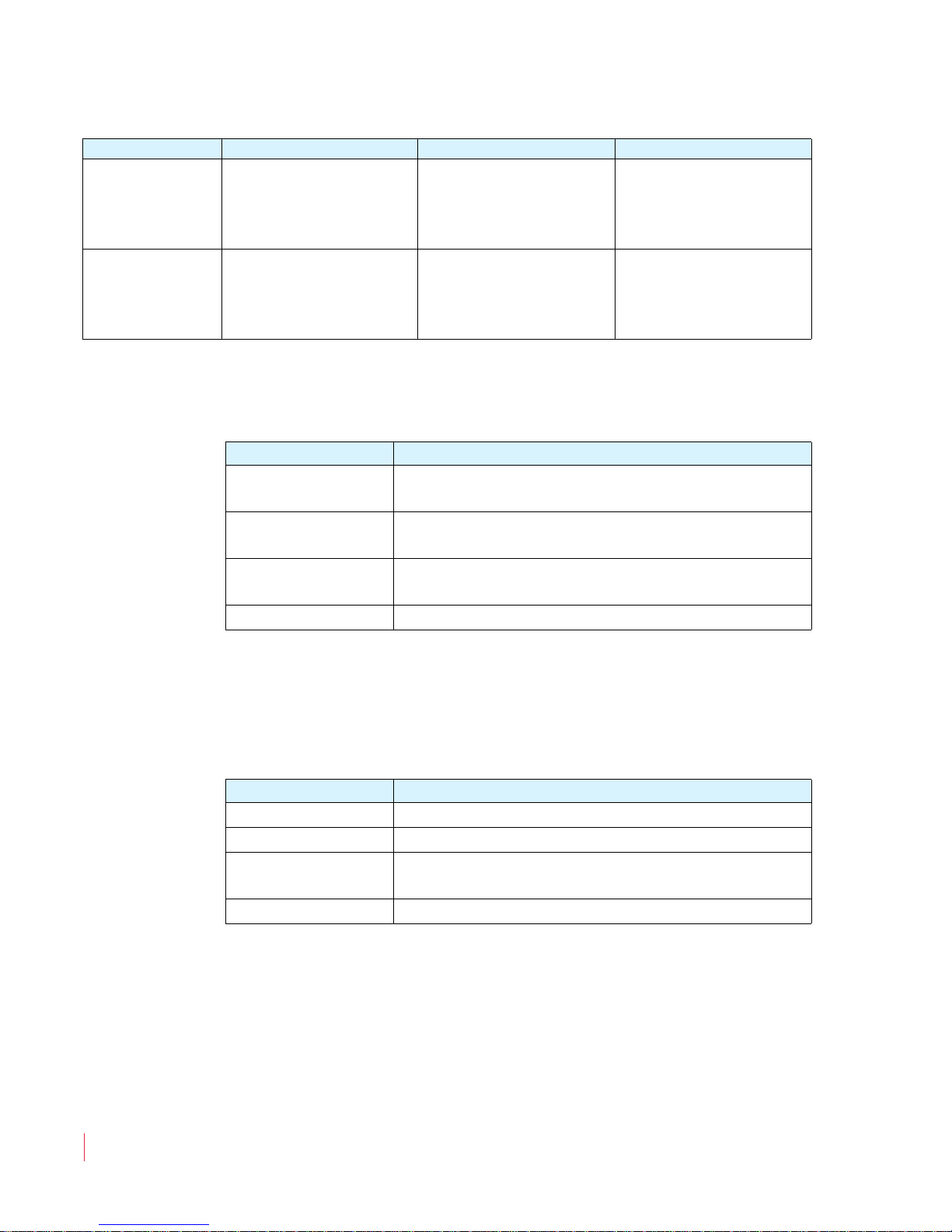
Table 2–1 White Control Functionality
Button Setup Mode Single-Channel Mode Pair Mode
Attaches the left
Left Up
Left Down
Selects the next option
for any given menu.
Selects the previous
option for any given
menu.
speaker to the next
higher-numbered
channel.
Attaches the left
speaker to the next
lower-numbered
channel.
Selects the next
higher-numbered
pair.
Selects the next lowernumbered pair.
© 2011 Wohler Technologies, Inc. All rights reserved.
821030: AMPx-S8 Series User Guide
11
Page 22
Chapter 2 System Overview
Front Panel Controls
Table 2–1 White Control Functionality (Continued)
Button Setup Mode Single-Channel Mode Pair Mode
Right Up
Right Down
Like an “Escape” key:
Cancels and returns to
the previous menu
option
Like an “Enter” key:
Accepts changes, or
drills deeper into the
menu structure.
Attaches the right
speaker to the next
higher-numbered
channel.
Attaches the right
speaker to the next
lower-numbered
channel.
Selects the next
higher-numbered
pair.
Selects the next lowernumbered pair.
• Blue for functions controlled by the Fn button.
Table 2–2 Blue Control Functionality
Button Functionality
Fn + Single
Fn + Pairs
Fn + Downmix
Fn + Setup
Selects single channel monitoring mode: one
channel per speaker, selected independently
Selects pair monitoring mode: one channel per
speaker, selected pair by pair
Selects downmix mode: one of several available
downmixes
Displays the Setup menu
• Yellow indicates the button functions for the
Setup menu. Refer to
Chapter 5 on page 43 for more details about using the Setup menu
for system configuration.
Table 2–3 Yellow Control Functionality
Button Functionality
Esc
Enter
Displays the previous menu item
Displays the next menu item
Returns to the previous menu and cancels
changes
Returns to the previous menu and saves changes
Menu Navigation
When making changes to the Setup menu, you will generally press the
Enter button to select menu options and settings, and press the Esc
(Escape)
normal operation.
button to back out of the menu, setting, or display to return to
821030: AMPx-S8 Series User Guide
12
© 2011 Wohler Technologies, Inc. All rights reserved.
Page 23
Rear Panel Connectors
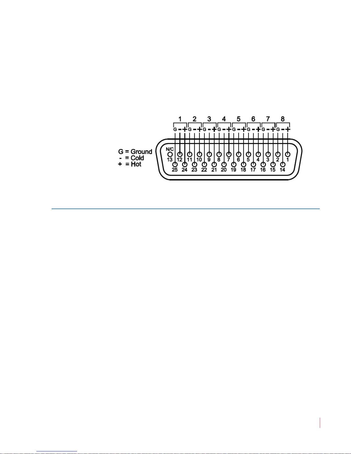
• Analog In (DB-25-F): This connector accepts balanced, low
impedance, line level analog signals. See Figure 2–4 below for pinout information.
Figure 2–4 Analog Input Connector Pin-Out
Chapter 2 System Overview
Rear Panel Connectors
Input Connectors
• Power: Attach a standard IEC-320 power cord between this
connector and AC mains power.
• AES/PCM In (1 through 4, BNC-F): These connectors accept
unbalanced (75 ) PCM (AES/EBU) formatted signals. These inputs
appear as AES1 in the LCD screen.
If you are not connecting downstream equipment, then you should
terminate the selected input connector. Otherwise, unterminate
them.
• AES/PCM In (and Loop Out) (DB-25-F): This connector accepts
balanced (110 ) AES signals. Inputs are internally connected to the
loop-through outputs. These inputs are referred to as AES2 in the
LCD screen. If you are connecting downstream equipment to the
AES loop-through outputs of this connector, then you should
unterminate this connector. If you are not connecting downstream
equipment, then you should terminate them. Refer to Terminating/
Unterminating Inputs on page 35 for details.
Note:
The pin-out for this connector is compatible with
Tascam DB-25 to XLR cable assemblies. Contact your
Wohler sales representative for availability. (Wohler’s
contact information is on page ii of this document.)
821030: AMPx-S8 Series User Guide
© 2011 Wohler Technologies, Inc. All rights reserved.
13
Page 24
821030: AMPx-S8 Series User Guide
© 2011 Wohler Technologies, Inc. All rights reserved.
14
Chapter 2 System Overview
Rear Panel Connectors
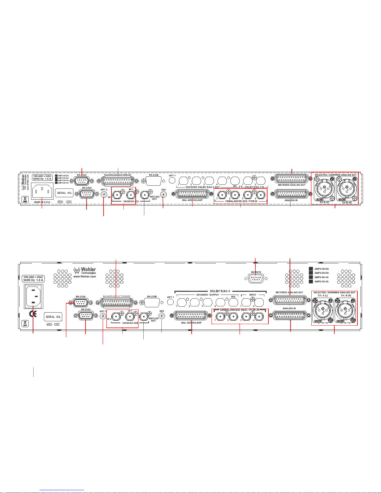
Figure 2–5 The AMP1-S8MDA-3G Rear Panel
Figure 2–6 The AMP2-S8MDA-3G Rear Panel
Power
SDI Option 2
SDI In (1 & 2)
SDI Re-Clocked Out
Reference
AES Bal In & Loop Out
AES/PCM In (1 thru 4)
Analog In
Selected/Downmix
Analog Out (L&R)
Standard Unbalanced AES Out (HD-15) can be replaced
with Balanced AES Out from SDI (DB-25) shown.
Metered Analog Out
RS-232C
RS-232 A
Power
RS-232C
SDI In (1 & 2)
SDI Re-Clocked Out
Ref
AES Bal In &
Loop Out
Analog In
Selected/Downmix
Analog Out (L&R)
Remote
Metered Analog Out
AES/PCM In (1 thru 4)
RS-232A
Opt 2
Standard Unbalanced AES Out (HD-15) can be replaced
with Balanced AES Out from SDI (DB-25) shown.
Page 25
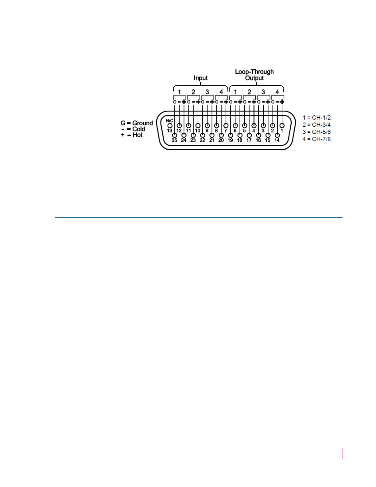
Chapter 2 System Overview
Rear Panel Connectors
Figure 2–7 AES/PCM Input and Loop-Through
DB-25 Pin-Out
• 3G/HD/SD-SDI In (1 and 2, BNC-F): These inputs accept SDI video
signals for the 3G models.
Note:
Output Connectors
• Metered Analog (DB-25): This connector outputs the analog signal
that is displayed on the front panel level meters. The pin-out
information for this DB-25 is identical to that of the Analog Input
connector. See Figure 2–5 on page 14.
Note:
The DA model does not feature SDI capability.
The Analog Output Preference (AOutputPref) entry
within the Setup Menu determines how this connector
outputs the speaker assignment when a DM1, DM2, or
DM3 downmix selection is enabled. The default setting
is Downmix, which outputs the metered signal with
individual channel scaling (gain settings) intact as
determined by the selected downmix (DM1, DM2, or
DM3). If Discrete is selected, then all metered
channels are output from these connectors at unity gain.
See Analog Output Preference Mode on page 46 for
information on how to set this parameter.
• 3G/HD/SD-SDI Re-Clocked Out (BNC): This connector outputs a
re-clocked copy of the SDI signal fed to the SDI input connector
selected for monitoring. When an SDI input is not selected for
monitoring in the unit,
this output by default.
• AES Unbalanced Out from SDI (HD-15): This connector outputs
de-embedded audio. The last SDI input and group selection
SDI In 2 will be reclocked and connected to
821030: AMPx-S8 Series User Guide
© 2011 Wohler Technologies, Inc. All rights reserved.
15
Page 26
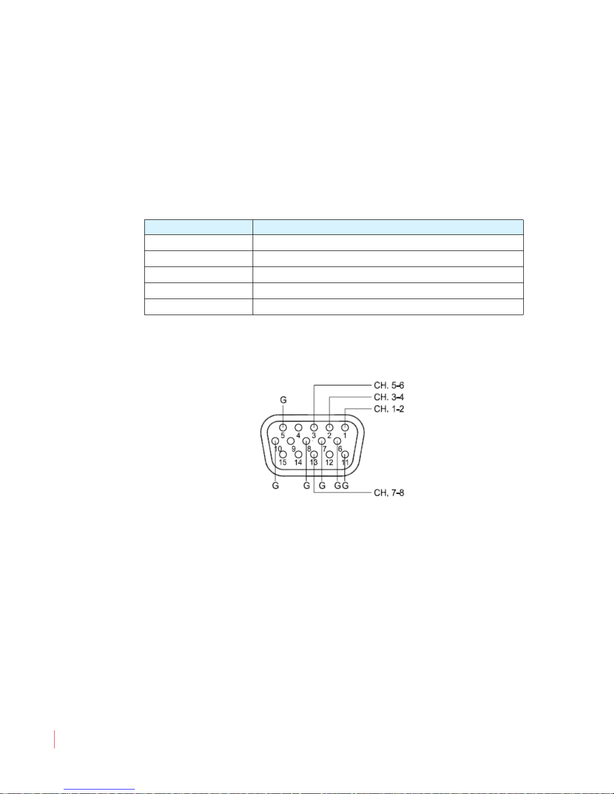
Chapter 2 System Overview
Rear Panel Connectors
determine which audio pairs are de-embedded on these 75 ,
unbalanced, AES outputs. No other monitoring function affects
these outputs.
The pinout of this connector is the same as that for a standard VGA
cable. VGA cables may be used to break out the HD-15 connectors
into separate BNCs.
Note:
The DA model does not feature SDI capability.
Table 2–4 VGA Connector Pin-Out
SDI Channels Cable Color/Function
1 and 2 Red
3 and 4 Green
5 and 6 Blue
7 and 8 Grey/H-Sync.
Not Used Black/V-Sync.
Figure 2–8 AES Unbalanced Out from SDI
HD-15 Pin-Out
Note:
You must specify either the balanced (DB-25) or the default
unbalanced (HD-15) output connector at the time you place
your order.
• (Optional) Balanced AES Output from SDI Input (DB-25): This
connector outputs de-embedded audio. The last SDI input and
group selection determine which audio pairs are de-embedded on
these 110 , unbalanced, AES outputs. No other monitoring
function affects these outputs.
The pin-out for this connector is compatible with Tascam DB-25 to
XLR cable assemblies. Contact your Wohler sales representative for
availability. (Wohler’s contact information is on page ii of this
document.).
821030: AMPx-S8 Series User Guide
16
© 2011 Wohler Technologies, Inc. All rights reserved.
Page 27
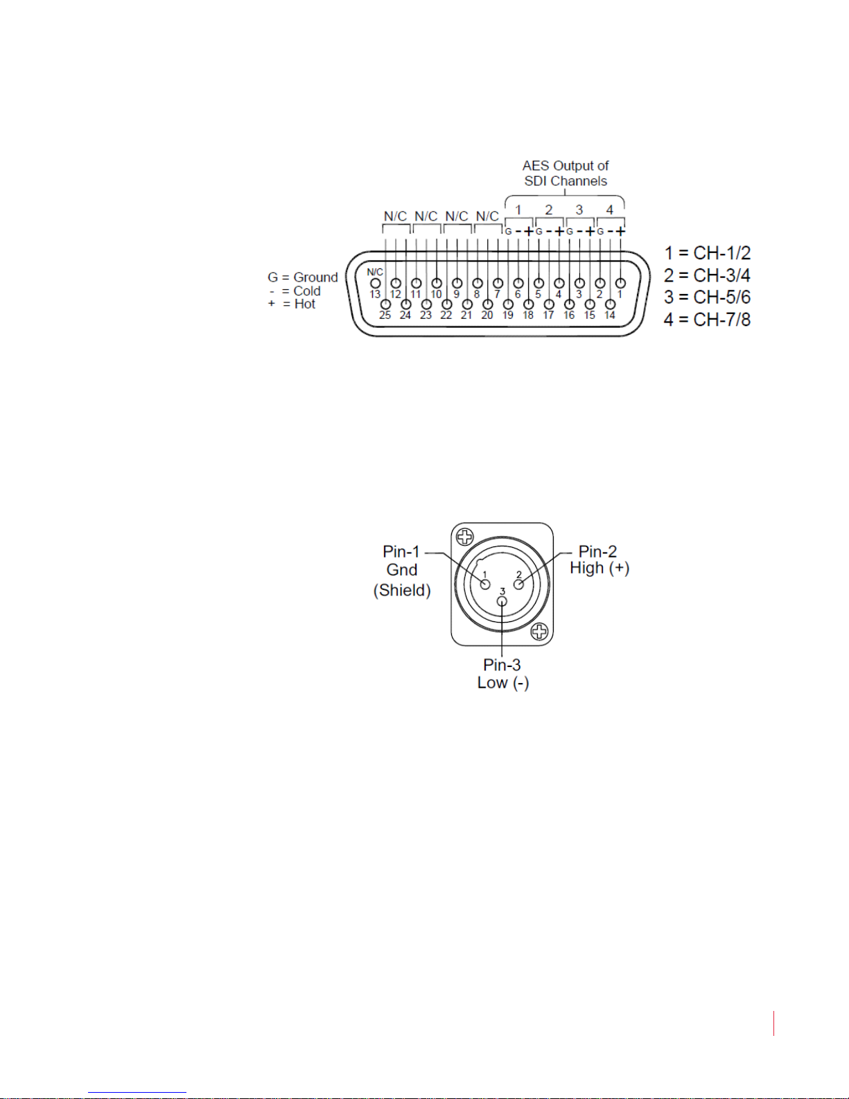
Chapter 2 System Overview
Rear Panel Connectors
Figure 2–9 AES Balanced Out from SDI
DB-25 Pin-Out
• Selected Downmix/Analog Out (Left and Right, XLR-M): These
connectors are balanced analog outputs of the speaker assign (or
downmix) source as selected for the left and right speaker channels.
See the pin-out diagram in Figure 2–10 on page 17.
Figure 2–10 XLR-M Pin-Out
• AES Bal In/Loop Out (DB-25): This connector contains both inputs
and looped outputs. Refer to AES/PCM In (and Loop Out), page 13
for a full description.
821030: AMPx-S8 Series User Guide
© 2011 Wohler Technologies, Inc. All rights reserved.
17
Page 28
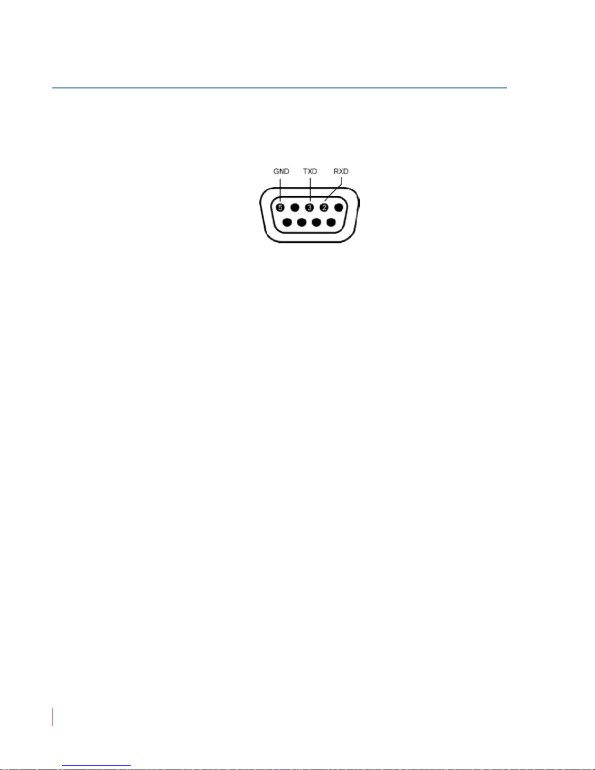
Chapter 2 System Overview
Rear Panel Connectors
Programming and Remote Access Connectors
RS-232 Connectors
Figure 2–11 RS-232 Pin-Out
• RS-232 A (DB-9): This connector is used for downloading
programming, setup, and diagnostic information into and out of the
main board.
• RS-232 B (DB-9): Not Used
• RS-232 C (DB-9) (not available on the DA models): This connector
is used for downloading programming, setup, and diagnostic
information into and out of the 3G card.
Remote Connector
Remote (DB-9) (2RU models only): When equipped with the optional
RC4-4 interface board and configured in software, this connector (not
RS-232) provides limited remote control and status reporting with
GPI/O signals: four inputs (Controls 1 through 4) and four outputs
(Status 1 through 4).
Note:
For more complete information about the functionality of
the Remote connector, contact your Wohler technical
support representative and ask for the documents with part
numbers 824016 and 824017.
821030: AMPx-S8 Series User Guide
18
© 2011 Wohler Technologies, Inc. All rights reserved.
Page 29
Rotary Switch Connectors
• OPT 2 (10-Position Rotary Switch): This recessed 10-position rotary
switch allows for standard operation and software upgrades. Refer
to Table 2–5 for the position values.
Table 2–5 OPT 1 and OPT 2 Option Settings and
Descriptions
Position Setting Description
0 thru 7 Operational Mode (Default=1)
8 thru 9 Software Upgrade
• SDI Option (10-Position Rotary Switch): This recessed 10-position
rotary switch that is reserved for future use and should be left at the
factory position of 1.
Table 2–6 SDI Option Settings and Descriptions
Chapter 2 System Overview
Rear Panel Connectors
Position Setting Description
0 Not Used - Reserved for Future Use
1 Operational Mode
2 thru 8 Not Used - Reserved for Future Use
9 Software Upgrade
• Ref (10-Position Rotary Switch): This recessed 10-position rotary
switch allows you to set the analog and digital reference levels for
the unit’s level meters, as well as to select the software upgrade
function. In Table 2–7 below, the analog reference level (analog, left
column) is the analog input level needed to activate the bar graph
segment at the associated digital reference level (digital, right
column) value. This is usually the location on the bar graph level
meter where the color transitions from green to amber.
Table 2–7 Reference Setting Values and Definitions
Position
Analog (dBu) Digital (dBFS)
Reference Level Function
0+8
-201+4
20
30 -18
4+6 -9
5+4 -18
821030: AMPx-S8 Series User Guide
© 2011 Wohler Technologies, Inc. All rights reserved.
19
Page 30
Chapter 2 System Overview
Monitoring Inputs
Table 2–7 Reference Setting Values and Definitions
Position
6 Custom Settings for Alternate Scales
7Not Used
8
9
Example: Choosing position 2 (0 dBu = -20 dBFS) means an analog input level of
0 dBu will light up the LED segment associated with the digital -20
dBFS value on the bar graph meter and also transition from green to
amber at that segment.
Analog (dBu) Digital (dBFS)
Reference Level Function
For software Upgrades Only
Monitoring Inputs
System Overview
The following simple instructions will allow you to get your AMPx-S8
Series monitor up and running quickly; that is, you will be able to
monitor any single input through the monitor’s internal speakers.
Referring to the AMPx-S8 Series rear panel diagrams (Figure 2–5 and 2–
6 on page 14) and the front panel controls (Figure 2–1 and 2–2 on page
9) follow the instructions below by signal/connector type.
Note:
For a complete description of each front panel control, refer
to Front Panel Controls on page 8.
For a complete description of each rear panel connector,
refer to Rear Panel Connectors on page 13.
Monitoring an Analog Input
1. To monitor an analog signal, connect the analog input to the rear
panel Balanced Analog In (DB-25) connector.
2. On the front panel, press the Input button until the LCD screen
displays Analog.
821030: AMPx-S8 Series User Guide
20
© 2011 Wohler Technologies, Inc. All rights reserved.
Page 31
3. Continue on to Channel Selection and Mixing on page 22.
Monitoring an AES Input
1. To monitor an AES signal, do one or both of the following:
• Connect an unbalanced AES signal to the rear panel AES/
PCM In
• Connect a balanced AES signal to the rear panel AES Bal In
& Loop Out
2. On the front panel, press the Input button until the LCD screen
displays the corresponding input you want to monitor:
• AES1 for an unbalanced signal (connected to BNC 1).
• AES2 for a balanced signal (connected to the DB-25).
1 (BNC), and/or
(DB-25).
Chapter 2 System Overview
Monitoring Inputs
Table 2–8 AES Input to Channel Relationship
AES BNC Connector Channel Outputs
1 1 and 2
2 3 and 4
3 5 and 6
4 7 and 8
3. Refer to Terminating/Unterminating Inputs on page 35 to check/
set your termination settings.
4. Continue on to Channel Selection and Mixing on page 22.
Monitoring an SDI Input
1. To monitor an SDI signal, do one or both of the following:
• Connect an SDI signal to the rear panel SDI In 1 (BNC), or
• Connect an SDI signal to the rear panel SDI In 2 (BNC).
2. On the front panel, press the
the corresponding input you want to monitor:
• SDI1 for a signal to the
• SDI2 for a signal to the
Input button until the LCD displays
SDI In 1 (BNC), or
SDI In 2 (BNC).
821030: AMPx-S8 Series User Guide
© 2011 Wohler Technologies, Inc. All rights reserved.
21
Page 32
Chapter 2 System Overview
Channel Selection and Mixing
3. Continue on to Channel Selection and Mixing immediately below.
Channel Selection and Mixing
AES
Example:
Note:
The level meters will operate automatically, displaying
volume levels for each channel carrying an input signal.
To produce audio through the internal speakers, press each of the
Speaker Assign buttons ( on page 20) until each channel is output
through the speaker of your choice. See Table 2–9.
Table 2–9 Speaker Assign Button Functionality
Button Press LED Color Speaker
1st Steady Green Left
2nd Flashing Green/Amber Both
3rd Steady Amber Right
4th Off Neither
Suppose you are monitoring an AES pair connected to the unbalanced
AES/PCM In 1. When AES1 is selected for input, the left channel of
the AES pair will appear on the meter for Channel 1, and the right on
Channel 2. Press the Speaker Assign button for Channel 1 until the
Channel LED turns green. Press the Speaker Assign button for
Channel 2 until the Channel LED turns amber. The left channel of the
AES pair now sounds in the left speaker, and the right channel in the
right speaker..
821030: AMPx-S8 Series User Guide
22
© 2011 Wohler Technologies, Inc. All rights reserved.
Page 33

Audio Configuration
Introduction
Overview
This chapter is the “how to” chapter. All topics listed below are sorted
alphabetically for easy reference. For information about presets refer to
Chapter 4: Presets on page 37.
Topics
CHAPTER 3
Topics Page
Introduction 23
Analog Output Preference 24
Monitoring and Mixing Modes 25
Muting the Speakers 29
Phase Correlation 30
SDI Inputs 31
Selecting the Input Signal 33
Setting the Monitor’s Startup Configuration 34
Terminating/Unterminating Inputs 35
821030: AMPx-S8 Series User Guide
© 2011 Wohler Technologies, Inc. All rights reserved.
23
Page 34
Chapter 3 Audio Configuration
848131 3.03
Setup: AOut Pref
-- Setup --
Aout Pref: Discr
-- Setup --
Aout Pref: D-mix
Analog Output Preference
Analog Output Preference
The Analog Output Preference determines how the Selected/
Downmix Analog Output
Output
DM2, or DM3 downmix options are selected. Refer to Rear Panel
Connectors on page 13.
The default setting is Downmix, which outputs the speaker assign with
individual channel scaling (gain settings) intact as determined by the
selected downmix. However, if you select Discrete, then all channels
with the downmix are output from these connectors at unity gain
without scaling of the channels as determined by the selected downmix.
To change the analog output settings:
1. Hold the Fn button while pressing the Setup button.
connector output the metered signals when either the DM1,
connectors and the Metered Analog
2. Press the Down button until the LCD screens AOutPref as shown
in Figure 3–1 below.
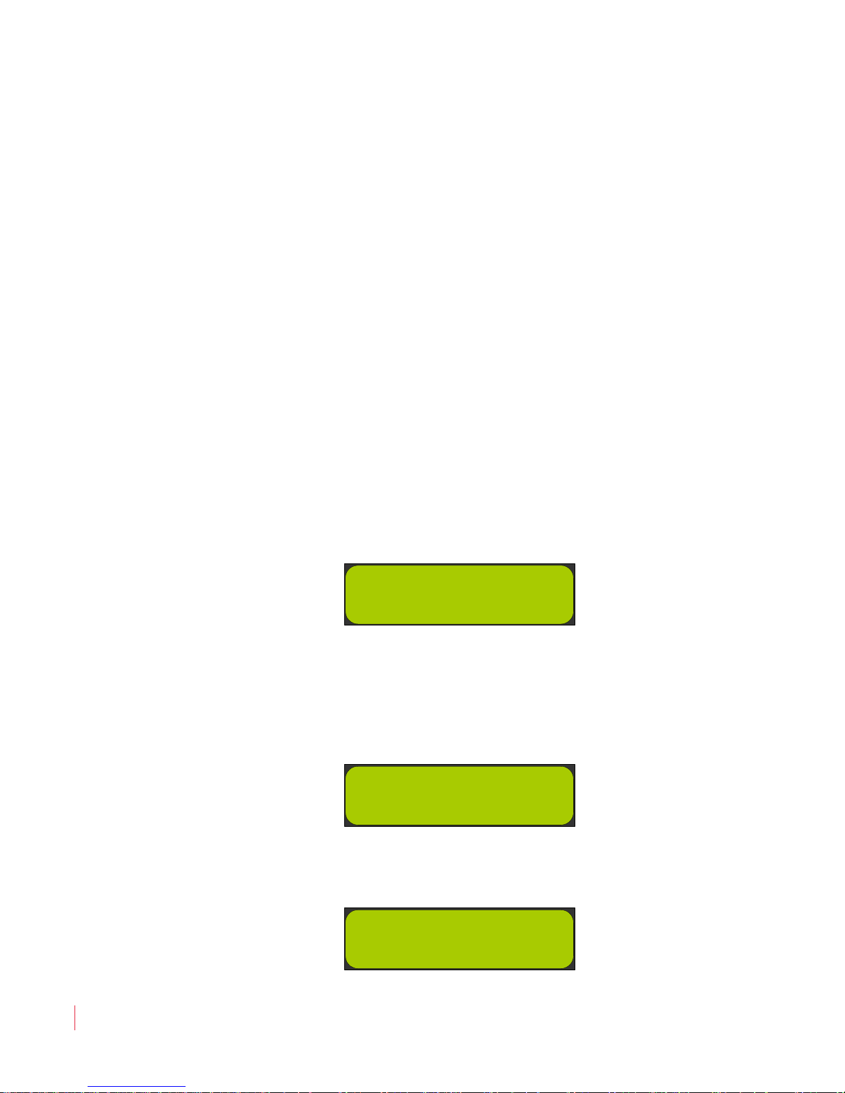
Figure 3–1 Analog Output Preference LCD screen
3. Pressing the Enter button displays either Figure 3–2 or Figure 3–3
depending on the current setting.
Figure 3–2 Analog Output Preference Setting -
Discrete
Figure 3–3 Analog Output Preference Setting -
Downmix
821030: AMPx-S8 Series User Guide
24
© 2011 Wohler Technologies, Inc. All rights reserved.
Page 35
Chapter 3 Audio Configuration
MIX AES1 MIX
1 3
2 4 - -
Monitoring and Mixing Modes
4. Press either the Up or Down arrow followed by the Enter button
to change the setting, or press the Escape button to leave it as is.
5. Press the Escape button again to return to normal operation.
Monitoring and Mixing Modes
Arbtrary Mixing
1. Press any of the eight speaker assign buttons to activate the mixing
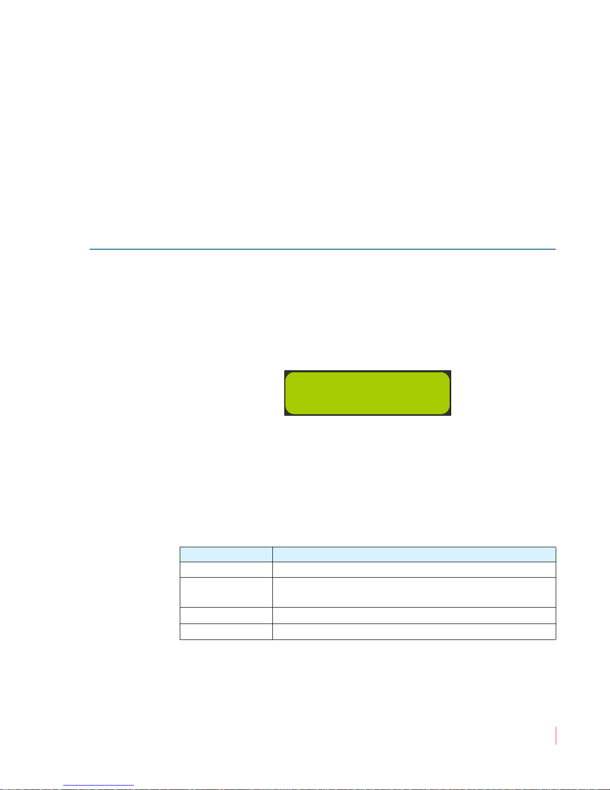
(summing) feature. This mode is indicated by the LCD screen
showing MIX in the upper right and left of the display. See Figure
3–4 below for an example.
Figure 3–4 LCD screen: Speaker Assign
2. Each subsequent press of a speaker assign button assigns the
selected channel to the left, both, right or neither speaker channel.
All eight channels may be mixed/summed in this way. With each
successive button press, the color of the associated speaker assign
LED, and the mixing/routing of that channel, cycles through the
following sequence
Table 3–1 Speaker Assign Selection
Button Press Results
1st Green (routed to left speaker only)
2nd
Alternating Green and Amber
(routed to both left and right speakers)
3rd Amber (routed to right speaker only)
4th Off (not mixed or routed into either speaker)
821030: AMPx-S8 Series User Guide
© 2011 Wohler Technologies, Inc. All rights reserved.
25
Page 36
Chapter 3 Audio Configuration
CH1 AES1 CH2
----
CH7 AES1 CH8
----
Monitoring and Mixing Modes
Single
This mode allows you to select one and only one signal for each speaker
independently of the other speaker and is most useful when you are
monitoring mono sources.
To select channels individually for each speaker:
1. Press the Fn + Single buttons to enable single channel selection.
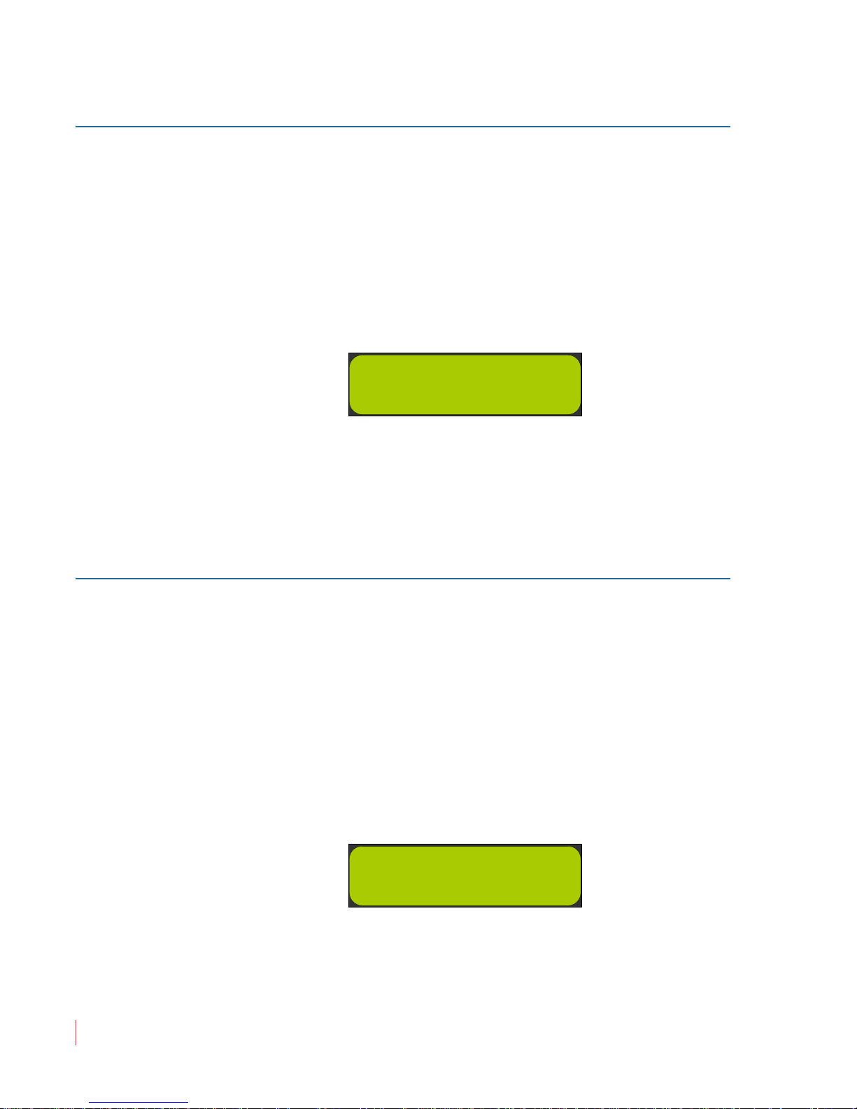
Figure 3–5 Single Channel Selection
2. Press the Left Up or Left Down buttons to cycle through the
channel selections for the left speaker. Likewise, press the Right
Up
or Right Down buttons to cycle through the channel
selections for the right speaker.
Pairs
This mode allows you to quickly assign one pair of channels to the
speakers. The selections are limited to Channels 1-2, 3-4, 5-6, and 7-8.
In all cases, the odd channel is sent to the left speaker, and the even
channel to the right. This mode is most useful when you are
monitoring stereo sources.
To select channel pairs for each speaker:
1. Press the Fn + Pair buttons to enable channel pair selection.
Figure 3–6 Channel Pair Selection
2. Use the
Left Up, Left Down, Right Up or Right Down buttons
to cycle through the channel pair selections.
821030: AMPx-S8 Series User Guide
26
© 2011 Wohler Technologies, Inc. All rights reserved.
Page 37

Downmix
Chapter 3 Audio Configuration
Monitoring and Mixing Modes
This mode is most useful when multiple signals need to be mixed
together and monitored at the same time. DM1-3 are designed for 5.1
surround sound signals, and assume a channel arrangement of
(Channels 1-6 respectively):
• Left Front, Right Front,
• Center, LFE (Subwoofer),
• Left Surround, Right Surround.
4+4 Mode, Mix A, and Mix B are provided for other types of multichannel monitoring needs.
1. Press the Fn + Downmix buttons to enable Downmix mode.
2. Press the Left or Right button to cycle through the seven
available Downmix types to monitor through the speakers:
Note:
None of the available DM downmix modes include
Channel 4 because it normally carries the LFE channel
which is below 200 Hz.
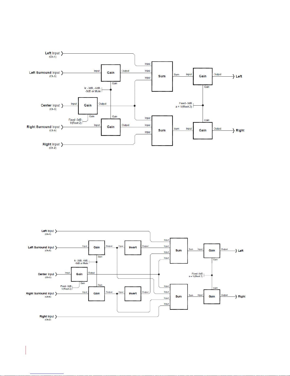
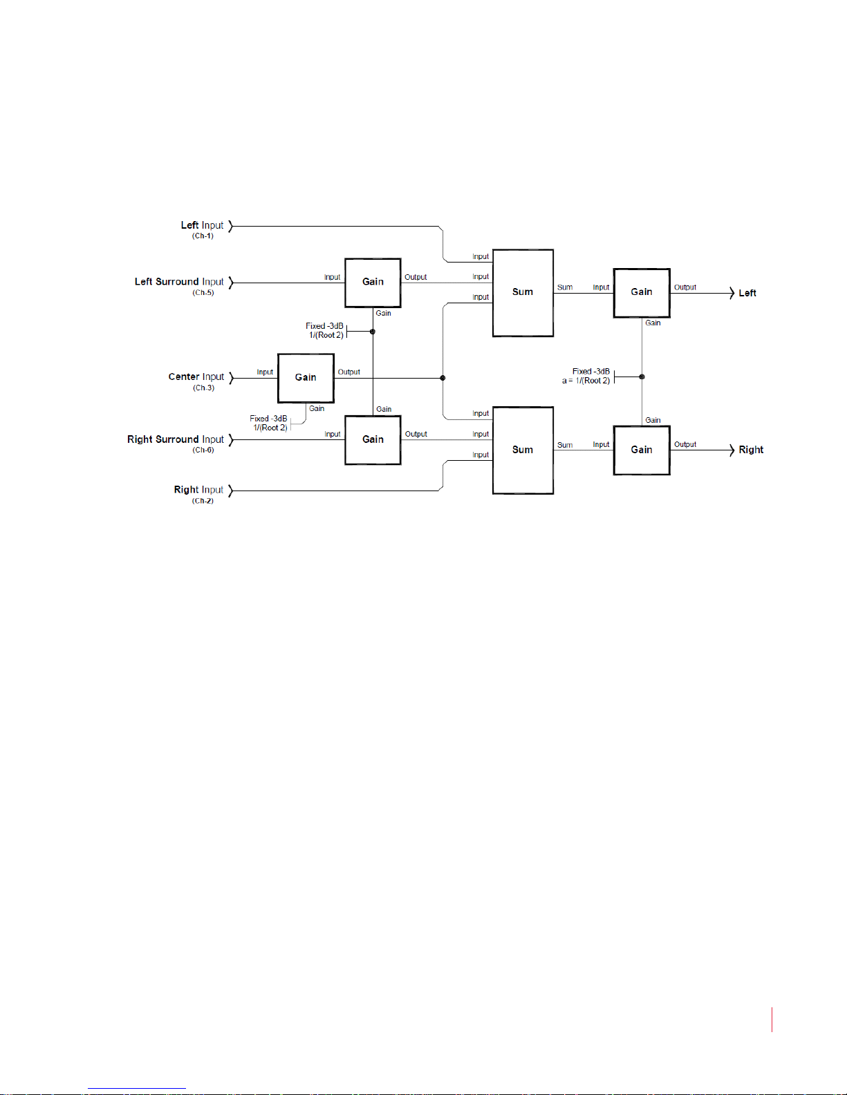
• DM1: This downmix is most suitable for a loudspeaker or
headphone downmix of a multi-channel program. Left and
left surround input channels mix into the left speaker, right
and right surround input channels mix into the right speaker.
Center input speaker assigns equally into both left and right
speakers. Contribution of the surround channel mix is set by
the Surround Gain entry in the
Setup Menu. DM1 is
equivalent to the Japanese ARIB Set 1 downmix formula. See
DM1 Mix Diagram on page 28.
821030: AMPx-S8 Series User Guide
© 2011 Wohler Technologies, Inc. All rights reserved.
27
Page 38
Chapter 3 Audio Configuration
Monitoring and Mixing Modes
Figure 3–7 DM1 Mix Diagram
• DM2: You can use this downmix to create a two speaker
assignments that can be decoded to multi-channel program
by the use of an external surround decoder. Contribution of
the surround speaker Assign is set by the surround level
entry in the
Setup Menu. DM2 is equivalent to the Japanese
ARIB Set 2 downmix formula. See Figure 3–8 below.
Figure 3–8 DM2 Mix Diagram
821030: AMPx-S8 Series User Guide
28
© 2011 Wohler Technologies, Inc. All rights reserved.
Page 39
Chapter 3 Audio Configuration
Muting the Speakers
• DM3: This downmix is the same as DM1 except that the
surround level is fixed at –3 dB. DM3 is equivalent to the
Japanese ARIB Set 3 downmix formula. See Figure 3–9 below.
Figure 3–9 DM3 Mix Diagram
• 4+4: In this downmix Channels 1 through 4 are summed to
the left speaker and Channels 5 through 8 are summed to the
right speaker.
• MXA and MXB: Select one of these two downmixes to
custom mix by adding Channels 1 through 8 into the left or
the right speakers using the Speaker Assign buttons.
• MIX: This mode appears whenever the Speaker Assign
buttons are pressed. The selection made in this mode is lost
whenever another mode is selected, or a preset is recalled.
Presets saved in MXA or MXB mode are recalled in this mode.
Muting the Speakers
The AMPx-S8 Series monitor provides two methods for muting the
internal speakers:
1. Plug in a pair of headphones, or
2. Press the
Mute button.
© 2011 Wohler Technologies, Inc. All rights reserved.
821030: AMPx-S8 Series User Guide
29
Page 40
Chapter 3 Audio Configuration
Phase Correlation
Pressing the Mute button allows you to step through three mute
states and an unmuted state. When the system is in one of the
mute states, all other information normally shown in the LCD such
as the Input Status Display is disabled. In addition, all other
buttons are disabled until you unmute the system. See Table 3–2
below.
Table 3–2 Mute Mode Functionality
Button Press Muted State
1st Mutes both left and right speakers
2nd Mutes the left speaker
3rd Mutes the right speaker
4th Returns the system to normal operation
Muting functions affect the signals to the speakers, headphones and the
rear panel
Selected/Downmix Analog Output connectors. Muting
does not affect the Metered Analog Ouputs except to defeat scaling.
These outputs reamain active even when the mute state is enabled.
Phase Correlation
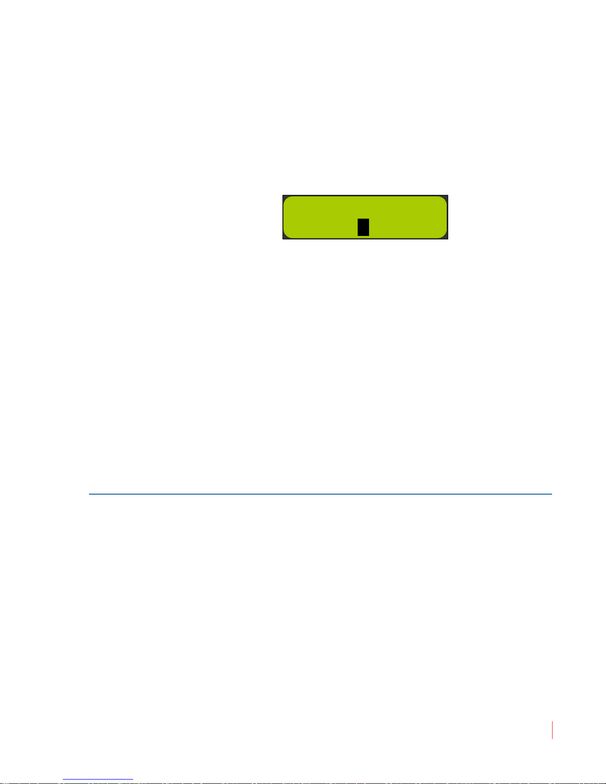
1. Pressing the button displays the phase correlation indicator in
the LCD screen.
The average correlation (phase) for the signal going through the left
speaker compared to the signal going through the right speaker is
indicated by a stationary block appearing in one of three positions on
the second line of the screen. A moving block indicates an
instantaneous (short term sample) phase correlation. Each of the three
positions has a different meaning.
• Center: Only one channel active, or zero (0) correlation between the
two channels
• Left (-): Selected channels are out-of-phase (-1 correlation
maximum)
• Right (+): Selected channels are in-phase (+1 correlation
maximum).
821030: AMPx-S8 Series User Guide
30
© 2011 Wohler Technologies, Inc. All rights reserved.
Page 41
Chapter 3 Audio Configuration
- Phase +
ٛ
ٛ
SDI Inputs
With typical stereo program material, the moving block display is
normal.
If the signals to the speakers are completely independent, they will
have a correlation result of 0, and the block will be stationary in the
center of the screen. See Figure 3–10 below for an example.
Figure 3–10 Phase Correlation Display
A mono in-phase signal fed to both right and left speakers would
put block being in the right-most position indicating the left and
right speaker signals are phase-identical.
The block will be on the far left for signals that are completely out of
phase.
2. Press any button to return to normal operation.
SDI Inputs
Selecting SDI Groups and Subgroups
When you select either of the SDI inputs for monitoring, the Group
button allows you to select which two, four-channel SDI audio groups
to display in the level meters.
When you press the buttons quickly, the selection order follows that
shown in Table 3–3 on page 32.
1. Press the
until the display flashes once.
Group button quickly to select the group and then wait
821030: AMPx-S8 Series User Guide
© 2011 Wohler Technologies, Inc. All rights reserved.
31
Page 42
Chapter 3 Audio Configuration
848131 3.03
Setup: SDI Delay
SDI Inputs
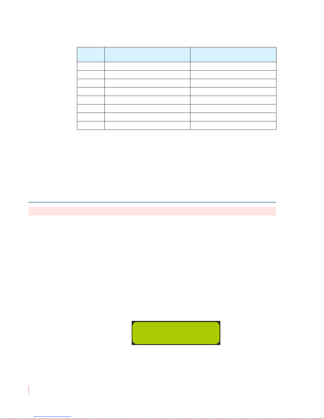
Table 3–3 SDI Group Select
Button
Press
Left Bar Graph Bank
(1 through 4)
1st Group 1 Group 2
2nd Group 3 Group 4
3rd Group 1 Group 2
4th Group 1 Group 3
5th Group 1 Group 4
6th Group 2 Group 3
7th Group 2 Group 4
8th Group 3 Group 4
2. Now press the Group button more slowly to toggle between
Group 1/2 and Group 3/4 selections.
After this, rapid presses will again initiate the cycling as shown in
Table 3–3. Since the first two selections are more common choices,
this features allows easy toggling between them.
Configuring for SDI Delay
Right Bar Graph Bank
(5 through 8)
Important:
This function only works for SDI signal types.
Modifying the SDI delay value allows you to precisely synchronize the
audio signal to a video signal. (The delay affects only the audio, not the
video.)
To change the SDI Delay setting:
1. Hold the
Fn button while pressing the Setup button.
2. Press the Down button until the LCD screens SDI Delay as
shown in Figure 3–11 below.
Figure 3–11 SDI Delay in the Setup Menu
3. Press the Enter button to select the option. The LCD display to an
image similar to that shown in Figure 3–12 below.
821030: AMPx-S8 Series User Guide
32
© 2011 Wohler Technologies, Inc. All rights reserved.
Page 43

Chapter 3 Audio Configuration
-Setup-
SDI Delay: 140 ms
Selecting the Input Signal
Figure 3–12 SDI Delay Setting
4. Press either the Up or Down buttons to select the delay in
milliseconds: Off or 0 to 170 (in 1 millisecond intervals).
5. Press the Enter button to make your selection and return to the
Setup Menu.
6. Press the
Escape button to return to normal operation.
Selecting the Input Signal
While the system is in normal operation, press the Input button to
cycle through each of the five selections. The selection is enabled when
it appears in the LCD screen. (Pressing the Enter button is not
necessary.)
• Analog
• AES
• AES1 (Unbalanced)
• AES2 (Balanced)
• SDI (not available in the DA model)
• Auto.SDI or Auto.SDI2 if no signal is present
• SD.SDI (signal is present and auto-detected)
• HD.SDI (signal is present and auto-detected)
• 3G.SDI (signal is present and auto-detected)
821030: AMPx-S8 Series User Guide
© 2011 Wohler Technologies, Inc. All rights reserved.
33
Page 44

Chapter 3 Audio Configuration
848131 3.03
Setup: Startup
Setting the Monitor’s Startup Configuration
Setting the Monitor’s Startup
Configuration
You can configure the AMPx-S8 Series monitor to start up from a
powered-off state, and automatically begin monitoring a particular
input.
1. Press the
2. Press the
in Figure 3–13 below.
Figure 3–13 Startup Menu Option
3. Press the
4. Press the Up or Down buttons to scroll through the startup
options. Note that only those options that are available in your
system will show up in the list.
• Last Used
• Analog
• AES 1
Fn + Setup buttons.
Down button until the LCD screens Startup as shown
Enter button to display the Startup list.
• AES 2
• SDI 1 (not available on DA models)
• SDI 2 (not available on DA models)
5. Press the
Setup Menu.
6. Press the Escape button to return to normal operation.
821030: AMPx-S8 Series User Guide
34
© 2011 Wohler Technologies, Inc. All rights reserved.
Enter button to make your selection and return to the
Page 45
Chapter 3 Audio Configuration
848131 4.00
Setup: Aes Term
AES Termination
Unbal. 1: Ena
AES Termination
Unbal. 1: Disa
Terminating/Unterminating Inputs
Terminating/Unterminating Inputs
Each of the AES and bitstream inputs on the AMPx-S8 may be
terminated or unterminated independently of each other. A given
input should be terminated when the AMPx-S8 is the last receiving
device in the signal path or is the only receiving device in the signal
path. If the signal loops through the AMPx-S8 to another receiving
device, the input should be unterminated in the AMPx-S8 (and
terminated at the last device in the signal path). Terminating the signals
properly improves signal integrity, and ensures the signal will be
received correctly by all the devices in the signal chain.
In the AMPx-S8 monitors, the terminations are set to "Enabled" by
default for the balanced AES inputs and unbalanced AES inputs inputs.
To change the termination settings:
1. Hold the Fn button while pressing the Setup button.
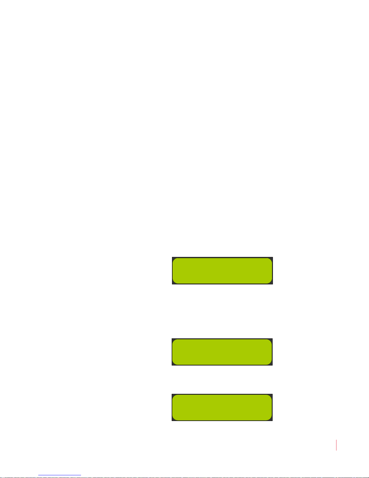
2. Press the Down button once. The LCD should look similar to the
image in Figure 3–14 below.
Figure 3–14 AES Termination Settings
3. Press the
Figure 3–15 or in Figure 3–16.
Figure 3–15 Termination Setting Currently Enabled
Enter key. The LCD should now look like the image
Figure 3–16 Termination Setting Currently Disabled
821030: AMPx-S8 Series User Guide
© 2011 Wohler Technologies, Inc. All rights reserved.
35
Page 46

Chapter 3 Audio Configuration
AES Termination
Save and Exit
Terminating/Unterminating Inputs
4. Press the Up or the Down buttons until the desired input is shown
on the screen.
5. Press the Enter key to change the termination setting for that
input.
Important:
Repeat Steps 4 and 5 until all the inputs have been set according to
your needs.
6. To exit the menu, press the
Up or Down arrow buttons until Save
and Exit appears in the LCD, as shown in Figure 3–17 below.
Figure 3–17 Saving and Exiting the Termination
Settings
7. To exit the Setup menu without saving your changes, press
Escape.
The termination selection order is:
• Unbalanced 1
821030: AMPx-S8 Series User Guide
36
© 2011 Wohler Technologies, Inc. All rights reserved.
• Unbalanced 2
• Unbalanced 3
• Unbalanced 4
• Balanced 1
• Balanced 2
• Balanced 3
• Balanced 4
• Save and Exit
Page 47

Introduction
Overview
This chapter describes how to create, recall, modify, and erase presets. It
also discusses using Preset mode for fast system configuration.
Topics
CHAPTER 4
Presets
Topics Page
Introduction 37
What are Presets? 38
Methods of Accessing the Presets 38
821030: AMPx-S8 Series User Guide
© 2011 Wohler Technologies, Inc. All rights reserved.
37
Page 48

Chapter 4 Presets
What are Presets?
What are Presets?
The AMP1-E8 is an incredibly flexible tool for monitoring multiple
audio streams. You can configure the entire system to function exactly
the way you want it to for your specific application. You can store a
complete system configuration into a preset. After saving one or more
presets, you can quickly scroll through them with the press of a single
button. The AMPx-S8 allows you to store up to 10 presets (numbered 0
through 9).
Methods of Accessing the Presets
Setup Menu
All presets can be stored, recalled, or erased through the Setup menu.
1. Press Fn+Setup to enter the Setup menu.
2. Use the Up and Down arrow buttons to select Save Preset,
3. Then press the Enter button.
Each of these menu items is described more fully in Chapter 5: Setup
Menu on page 43.
Preset Mode
This mode of operation is intended for situations where a number of
pre-defined unit configurations is all you need. This allows even the
most non-technical person to quickly scan through a list of sources to
monitor, without having to understand the operation of the rest of the
unit, or which source is plugged into which input of this unit.
Erase Preset, or Recall Preset.
In Preset mode, the Input button cycles through the defined presets.
With
Preset mode enabled, you can recall a preset by pressing only the
Input button to access each stored preset by name, rather than by
signal type.
821030: AMPx-S8 Series User Guide
38
© 2011 Wohler Technologies, Inc. All rights reserved.
Page 49

Chapter 4 Presets
Methods of Accessing the Presets
Note:
When this mode is enabled, you can no longer directly select
the inputs by the input type (e.g., AES 1, SDI 2, analog, and
so on). The inputs are accessed only indirectly through the
presets in this mode. To access the inputs by input type, you
must first disable Preset mode.
Enabling/Disabling Preset Mode
To enable or disable Preset mode:
1. Press Fn+Setup.
2. Use the Up and Down arrow buttons until PSet Mode appears in
the LCD window and press Enter.
Note:
3. Press the Up and Down arrow buttons to toggle between Disa
(disabled) and Ena (enabled). Press Enter to accept the new
setting, or press Escape to cancel the change. Either way, you will
be returned to the Setup menu.
This selection will not appear if all the presets are
empty. In this case, you will need to store at least one
preset to enable this menu item.
4. Press Escape again to return to normal operation.
Recalling a Preset
If Preset mode is enabled, press Input to recall the first available
preset. Subsequent presses will cycle through all the available presets.
Speaker Assign/Preset Buttons (Presets 1 through
4 Only)
Presets 1 through 4 get special attention. You can recall, save, or
overwrite them simply by pressing Fn+Preset x (where x represents
the corresponding
below the meters on the left side of the unit). In the following examples,
we’ll be using Preset 1.
Speaker Assign button immediately above or
821030: AMPx-S8 Series User Guide
© 2011 Wohler Technologies, Inc. All rights reserved.
39
Page 50

Chapter 4 Presets
Methods of Accessing the Presets
Saving a Preset
1. Press Fn+Preset 1.
If Preset 1 is currently empty, the system will prompt you to save
and name the current unit configuration to Preset 1.
2. Name the preset by using the Up and Down arrow buttons to
scroll through the available list of characters. Press Enter to accept
each character.
3. When you’re done entering all the characters, scroll until _DONE_
appears in the window, and press
Enter.
Note:
_DONE_ is located between the lowercase letters and
before the numbers.
Recalling a Preset
If, after pressing Fn+Preset 1, the preset is not empty, the system will
prompt you to recall Preset 1, and Preset 1's name will appear in the
LCD. If you press Enter, the system will recall the preset.
Overwriting a Preset
If the preset is not empty (after pressing Fn+Preset 1) the system will
prompt you to recall Preset 1, and its name will appear in the LCD.
1. If you press Escape while the preset recall prompt is showing, the
system will ask you if you want to overwrite the preset. If you
want to overwrite the preset with the unit's current settings, press
Enter.
2. Press
Enter to continue.
3. Save Old Name? will appear, with the selected preset number
and current name below it. If you wish to use the name displayed,
press
Enter, and skip the rest of the following instructions. Your
current settings are now stored in the selected preset.
Otherwise, if you wish to enter a new name, continue on with
Step 4 below.
4. Press Escape.
821030: AMPx-S8 Series User Guide
40
© 2011 Wohler Technologies, Inc. All rights reserved.
Page 51

Chapter 4 Presets
Methods of Accessing the Presets
5. Name the preset by using the Up and Down arrow buttons to
scroll through the available list of characters. Press Enter to
accept the character; repeat the process until all the characters have
been entered.
6. When all the characters have been entered, scroll until _DONE_
appears in the window, and press Enter.
Note:
_DONE_ is located between the lowercase letters and
before the numbers.
If you do not want to overwrite the preset, press Escape again, and the
unit will be returned to normal operation without recalling Preset 1 or
modifying it in any way.
821030: AMPx-S8 Series User Guide
© 2011 Wohler Technologies, Inc. All rights reserved.
41
Page 52

Page 53

Introduction
Overview
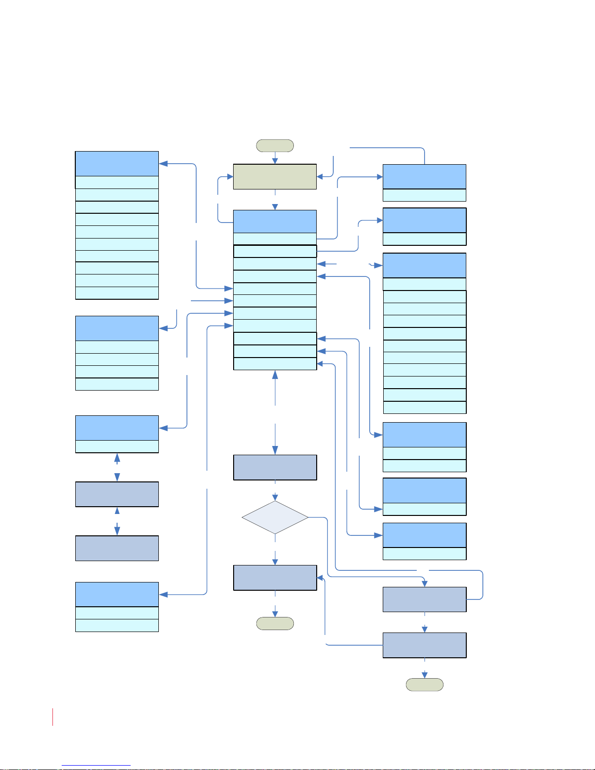
This chapter explains the options in the Setup menu. Figure 5–1 on page
44 provides a structural overview.
Topics
CHAPTER 5
Setup Menu
Topics Page
Introduction 43
Accessing Setup Mode 44
Analog Output Preference Mode 46
Recalling a Preset 46
Saving a Preset 47
Preset Mode 51
Erasing a Preset 51
SDI Delay 52
Startup 53
Surround Gain 53
Bitstream Detection 54
Phase Bits 55
821030: AMPx-S8 Series User Guide
© 2011 Wohler Technologies, Inc. All rights reserved.
43
Page 54
Chapter 5 Setup Menu
Fn + Setup
Normal Operation
Esc
Enter
Setup: AES Term
Unbal. 1: Ena/Disa
Balanced 1: Ena/Disa
Balanced 2: Ena/Disa
Balanced 3: Ena/Disa
Balanced 4: Ena/Disa
Unbal. 3: Ena/Disa
Unbal. 4: Ena/Disa
Unbal. 2: Ena/Disa
Bitstrm. 1: Ena/Disa
Bitstrm. 2: Ena/Disa
Save and Exit
Enter/Esc
Setup: AOutputPref
Discrete
Downmix
Enter
/Esc
Enter/Esc
Setup: Startup ++
Last Used
SDI 1
SDI 2
BSt 1
BSt 2
AES 1
AES 2
Analog
SDI 1 + DBY
SDI 2 + DBY
Enter
/Esc
Setup: Srnd Gain
Mute
-9 dB
-6 dB
-3 dB
Enter
/Esc
Setup: Erase PSet
0 through 9
Enter
/Esc
Setup: Pset Mode
Enable
Disable
Enter
/Esc
Unused?
No
Choose Preset Num
Preset0: DOLBY1
AES2 ?@<A>BC
Name: A_
OVERWRITE PRESET?
Preset1: DOLBY1
Save Old Name?
Preset1: DOLBY1
Enter
Esc
Enter
Esc
Setup Menu
AES Term
Startup
Srnd Gain
Erase Preset
Pset Mode +
Save Preset
AOutPref
RCallPSet +
Choose Preset Num
Preset0: AES MIX
Enter/Esc
ERASE PRESET?
Preset0: AES MIX
Enter/Esc
Choose Preset Num
Preset1: On Site
0 through 9
Normal
Normal
Normal
Enter/Esc
Enter
Yes
Enter
/Esc
SDI Delay
Setup: SDI Delay
Off through 170 ms
Enter
/Esc
A Vld Det
A Vld Det
Ena/Disa
Enter/Esc
Phase Bts
Phase Bts
Ena/Disa
Enter
/Esc
Accessing Setup Mode
Accessing Setup Mode
Figure 5–1 Setup Menu Tree
821030: AMPx-S8 Series User Guide
44
© 2011 Wohler Technologies, Inc. All rights reserved.
Page 55
Chapter 5 Setup Menu
Accessing Setup Mode
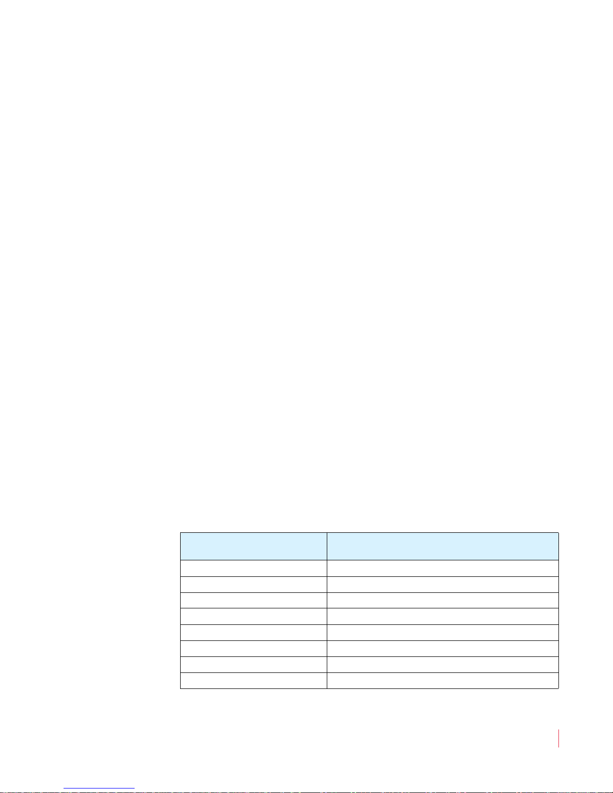
1. Enable Setup mode by pressing and holding the Fn button and
then pressing the Setup button. This mode is used to change unit
features.
2. You can step through the menu selections and parameters using
Up and Down buttons.
the
3. Press the
Enter button to save your selections. To cancel the
option and exit the menu, press the Escape button.
The current options in Setup Mode (as shown in Setup Menu Tree on
page 44) are:
• Preset Recall (RCallPSet)
• Preset Save (SavePSet)
• Preset Mode (PsetMode)
• Preset Erase (ErasePSet)
• SDI Delay (only available for the 3G model)
• Surround Gain (Srnd Gain)
• Startup
• Analog Output Preference (AOutPref)
After entering the Setup Menu, the display will indicate the software,
version number, and the menu selection: RCallPSet (if presets are
saved).
Table 5–1 Up Button List
Pressing the Up
Button the...
Changes the Display to...
1st time SavePSet
2nd time PSetMode (if presets are saved)
3rd time ErasePset (if presets are saved)
4th time SDI Delay (3G model only)
5th time Srnd Gain
6th time Startup
7th time A-OutPref
8th time RCallPSet
To select the current option, press the Enter button.
821030: AMPx-S8 Series User Guide
© 2011 Wohler Technologies, Inc. All rights reserved.
45
Page 56

Chapter 5 Setup Menu
Analog Output Preference Mode
To exit Setup Mode, press the Esc button.
Note:
The RCallSet, PSetMode, and ErasePSet options will
not be available if a preset has not been previously saved to
the unit. See Saving a Preset on page 47 for how to save a
preset of the current unit configuration.
Analog Output Preference Mode
To change the Analog Output Preference, select AOutputPref and
then press the Enter button.
This entry within the Setup menu is used to determine how the
Selected/Downmix Analog Out and Metered Analog Out
connectors on the rear panel output the metered signal when any of the
DM1, DM2, or DM3 downmix selections is enabled.
The default setting is Downmix, which outputs the speaker assign with
individual channel scaling (gain settings) intact as determined by the
selected downmix (DM1, DM2, or DM3). In addition, the channels are
summed at unity gain into the speakers and headphones. However, if
Discrete is selected, then all channels within the downmix are output
from these connectors at unity gain without scaling of the channels as
determined by the selected downmix. For example, the center channel
scaling is -3dB, and the surround channel scaling is set in the Setup
menu.
Recalling a Preset
1. Press the Fn + Setup button to display the Setup menu.
2. Press the Up button to display RCallPSet.
3. Press the
821030: AMPx-S8 Series User Guide
46
© 2011 Wohler Technologies, Inc. All rights reserved.
Enter button to select this option.
Page 57
Chapter 5 Setup Menu
Choose PresetNum
Preset1: Off Air
Choose PresetNum
Preset7: Unused
Saving a Preset
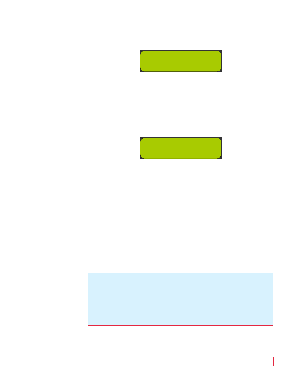
Figure 5–2 Recalling an Existing Preset
4. Press the Up and Down buttons to scroll through the presets.
In the example above (Figure 5–2), Preset 1 is called Off Air. If a
particular preset is not assigned, it will be indicated as Unused, as
shown in Figure 5–3 below.
Figure 5–3 Creating a New Preset
5. Press the Enter button with the desired preset displayed to recall
that preset. The unit returns to normal operation, reconfigured
according to the settings in that preset.
Saving a Preset
1. Press the Fn+Setup buttons to display the Setup menu.
2. Press either the
3. Press the
Decision Point:
If you want to create a brand new preset, continue on to Creating a
New Preset on page 48.
Enter button.
Up or Down buttons to display Save Preset.
Otherwise, if you want to overwrite an existing preset, continue on to
Overwriting an Existing Preset on page 49.
821030: AMPx-S8 Series User Guide
© 2011 Wohler Technologies, Inc. All rights reserved.
47
Page 58
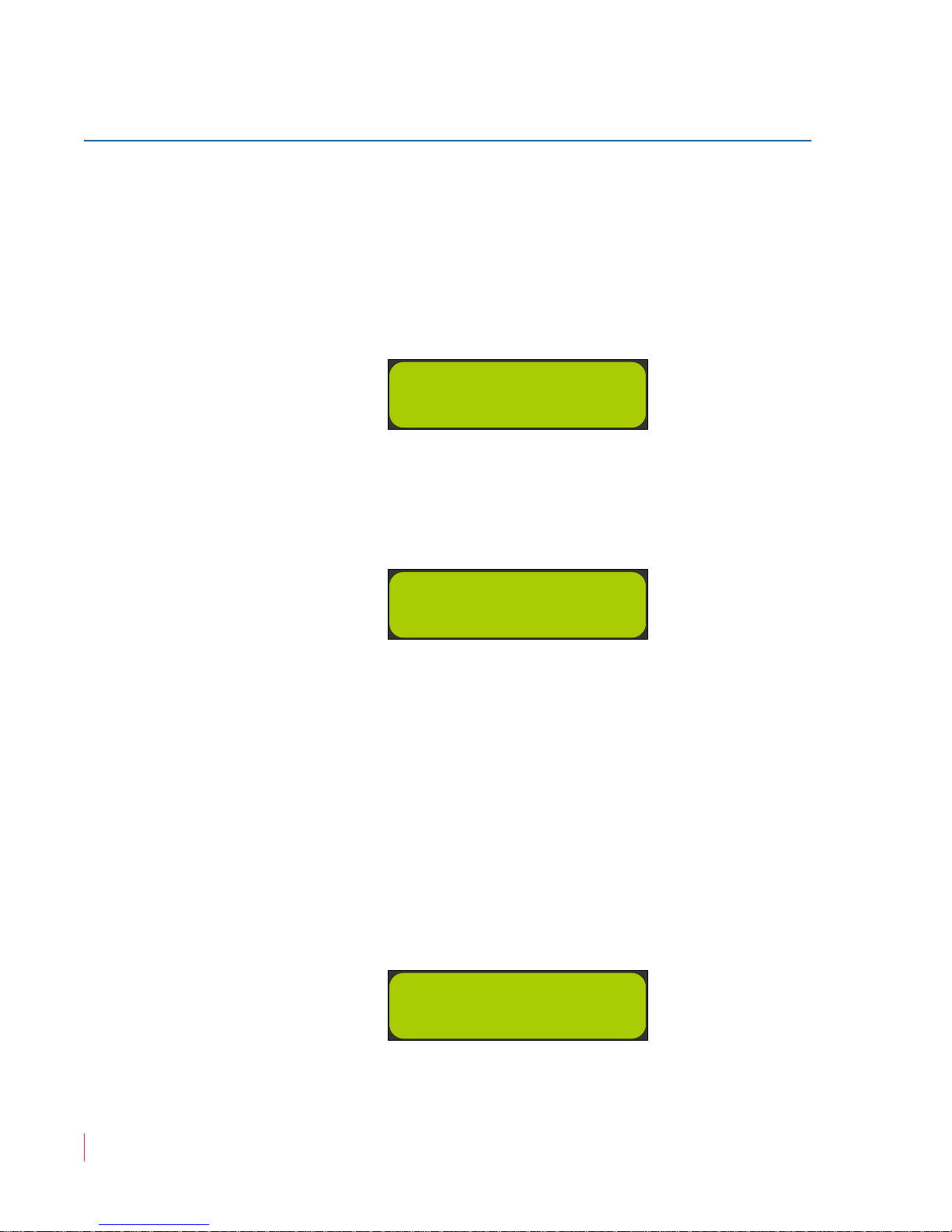
Chapter 5 Setup Menu
Choose PresetNum
Preset7: Unused
AES 1 ?@<A>BC
Name: A_
HD.SDI1 _DONE_
Name: HDSDI1
_
Saving a Preset
Creating a New Preset
Note:
To cancel the procedure at any time during this process,
press the Escape button and the preset will not be saved
and the unit will return to normal operation.
1. Press either the Up or Down buttons to choose any preset labelled
Unused.
Figure 5–4 Choose an Unused Preset
2. Press the Enter button to display a prompt for a new preset name
as shown in Figure 5–5.
Figure 5–5 Assigning the Name of a Preset
3. Scroll through letters (and symbols) using the Left Up and Left
Down
buttons. Press the Enter button to accept the current letter
shown in the display and move to the next letter. Repeat this
procedure until the display shows the name you want to use for
this preset.
Note:
Pressing the Enter button may display multiple letters,
but the only one that changes will be the one
immediately to the left of the underscore. As a result, it
may be necessary to start the procedure over again if
too many characters appear in the display.
Figure 5–6 Completed Preset Name Selection
821030: AMPx-S8 Series User Guide
48
© 2011 Wohler Technologies, Inc. All rights reserved.
Page 59
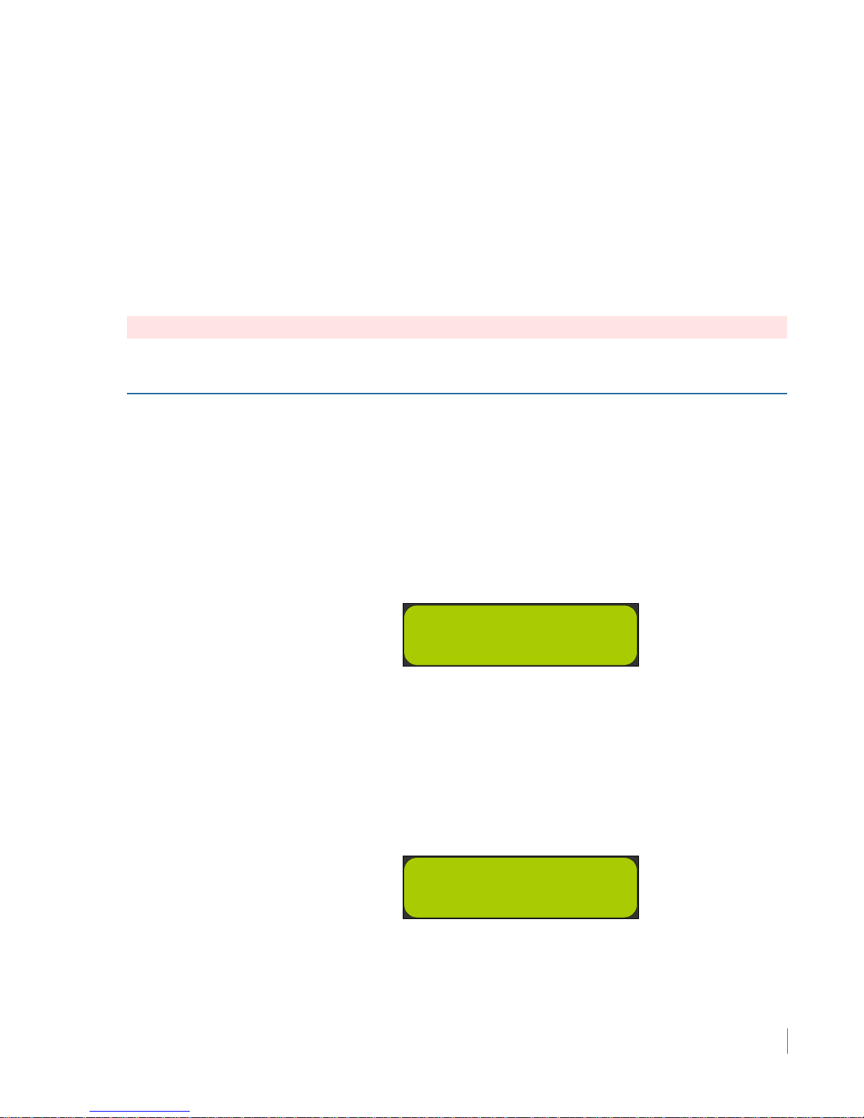
Chapter 5 Setup Menu
OVERWRITE PRESET
Preset1: Off Air
Save Old Name?
Preset3: Studio
Saving a Preset
Naming will automatically end after you select eight characters, or
when you press the Enter button when _DONE_ appears on the
display. See Figure 5–6 above.
Note:
The _DONE_ selection comes before the numerals, and
follows the lower case alphabet. The character order is
the order of ASCII characters.
After naming the preset, the current state of the system is saved
under that name and preset number, and the system returns to
normal operation.
Important:
This concludes the procedure for creating a new preset.
Overwriting an Existing Preset
1. Press either the Up or Down buttons to choose any preset that is
not labelled Unused.
Choosing an already used preset will display a warning to the user
that they are about to overwrite the preset, as shown in Figure 5–4
below.
Figure 5–7 Overwriting a Preset
2. Press the Enter button to display Save Old Name? (Figure 5–8
on page 49) with the selected preset number and current name
below it. If you wish to use the name displayed, press
skip the rest of the following instructions. Your current settings are
now stored in the selected preset.
Figure 5–8 Save Old Name?
Enter, and
821030: AMPx-S8 Series User Guide
© 2011 Wohler Technologies, Inc. All rights reserved.
49
Page 60

Chapter 5 Setup Menu
Studio ?@<A>BC
Name: A_
Saving a Preset
3. Pressing the Enter button keeps the old name for the new preset
and returns the unit to normal operation.
Important:
This concludes the procedure for overwriting an existing preset with
the same name.
Pressing the
Escape button displays a prompt for a new preset
name as shown in Figure 5–9 below.
Figure 5–9 Save New Name?
4. Scroll through letters (and symbols) using the Left Up and Left
Down
buttons. Press the Enter button to accept the current letter
shown in the display and move to the next letter. Repeat this
procedure until the display shows the name you want to use for
this preset.
Note:
Pressing the Enter button may display multiple letters,
but the only one that changes will be the one
immediately to the left of the underscore. As a result, it
may be necessary to start the procedure over again if
too many characters appear in the display.
50
Naming will automatically end after you select eight characters, or
when you press the Enter button when _DONE_ appears on the
display.
Note:
The _DONE_ selection comes before the numerals, and
follows the lower case alphabet. The character order is
the order of ASCII characters.
After naming the preset, the current state of the system is saved
under that name and preset number, and the system returns to
normal operation.
Important:
This concludes the procedure for overwriting an existing preset with a
new name.
821030: AMPx-S8 Series User Guide
© 2011 Wohler Technologies, Inc. All rights reserved.
Page 61

Preset Mode
Choose PresetNum
Preset1: Off Air
For more information about presets Refer to Chapter 5: Setup Menu on
page 43.
To enable or disable Preset mode:
1. Press Fn+Setup.
2. Use the Up and Down arrow buttons until PSet Mode appears in
the LCD window and press Enter.
Chapter 5 Setup Menu
Preset Mode
Note:
3. Press the Up and Down arrow buttons to toggle between Disa
(disabled) and Ena (enabled). Press Enter to accept the new
setting, or press Escape to cancel the change. Either way, you will
be returned to the Setup menu.
4. Press Escape again to return to normal operation.
This selection will not appear if all the presets are
empty. In this case, you will need to store at least one
preset to enable this menu item.
Erasing a Preset
This menu command allows you to erase a stored preset. Pressing the
Enter button will allow the user to choose a preset to erase.
Note:
If the unit does not have any stored presets, this menu item
will not appear.
Figure 5–10 Erasing a Preset - Choose the Preset
The Left and Right buttons select from among the available presets.
Once you press the
warn you that the preset will be erased.
Number
Enter button to select a preset, the system will
821030: AMPx-S8 Series User Guide
© 2011 Wohler Technologies, Inc. All rights reserved.
51
Page 62
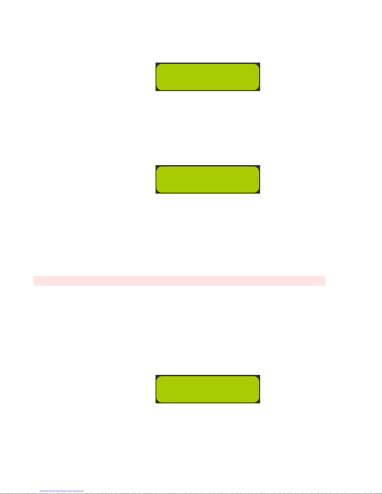
Figure 5–11 Erasing a Preset - Confirmation
Erase Preset?
Preset1: Off Air
Choose PresetNum
Preset2: VTR #2
-Setup-
SDI Delay: 140 ms
Pressing the Enter button will erase that preset. Pressing the Esc
button will not erase that preset. In either case, control returns to the
menu to choose another preset to erase.
Figure 5–12 Erasing a Preset - Select the Preset to
Erase
Press the
Monitoring Mode
SDI Delay
Important:
This menu item is not available if this unit has no de-embedder card.
This feature allows you to change the amount of delay added to the deembedded audio signals from the SDI inputs. This allows you to
compensate for video processing delays in external video signal chains
and monitors. This selection delays the monitored SDI audio and the
de-embedded SDI AES signals, but does not affect the reclocked SDI
output in any way.
Figure 5–13 SDI Delay
Esc button to exit Setup Mode and return to Normal
.
Step through settings using the
example). To accept, press the
exit Setup Mode and return to Normal Monitoring Mode.
Up or Down button, select 140 ms (for
Enter button. Press the Esc button to
Page 63

Startup
-Setup-
Srnd Gain -3dB
The Startup entry within the Setup Menu determines the input used
by the unit at power up. When set to Last Used, the unit will power
up the same way that the unit was before power was interrupted. If
instead you want to have the unit start up every time with the same
input selected, repeatedly press the Up/Down buttons until the
desired input is shown in the LCD. Save the selection by pressing the
Enter button. Press the Esc button to exit Setup mode and return to
normal operation.
Surround Gain
To change surround gain, select Srnd Gain and then press the Enter
button.
Chapter 5 Setup Menu
Startup
Important:
Figure 5–14 Erasing a Preset
Step through settings using the Up or Down buttons, select -9dB (for
example). To accept, press the Enter button. To exit without saving,
press the
Surround gain adjustments are only effective for downmixes DM1 and
DM2. In downmix DM3 the surround gain is fixed.
Esc button.
821030: AMPx-S8 Series User Guide
© 2011 Wohler Technologies, Inc. All rights reserved.
53
Page 64

Bitstream Detection
The unit will now mute an input pair if it detects the presence of a nonPCM stream (such as a Dolby or DTS bitstream) on that pair. The unit
detects bitstreams with two methods:
A. Preamble detection
B. Not-Audio AES Channel status flag is asserted
In terms of Method A, encoded bitstreams contain key data sequences
that identify the type of encoding used. These sequences are known as
preambles (see the SMPTE 337 and 338 standards). This unit can only
detect 16-bit preambles. For example, a 20-bit Dolby E stream would be
passed as PCM audio, instead of being flagged as an encoded stream.
This method is always employed.
In terms of Method B, the upstream equipment must either assert or
de-assert this flag. Unfortunately, not all equipment does this correctly.
In those cases where the channel status flag is set incorrectly, you may
need to disable this method of bitstream detection. This can be done
using the setup menu item A Vld Det. When enabled (Ena), Method B
is used to detect bitstreams. When disabled (Disa), Method B is not
used to detect bitstreams. If your unit is muting PCM streams, set this
item to Disa. If encoded bitstreams are getting through to the speakers,
set this item to Ena.
Page 65

Phase Bits
For units with SDI de-embedder cards installed, there is a new menu
item available, entitled Phase Bts, which stands for phase bits. These are
bits that are embedded in SDI streams that allow the audio sample rate
to be independent of the video pixel clock, and they are required by the
latest SMPTE standards. However, not all equipment implements these
bits correctly. Normally, this menu item should be left in the Ena
(enabled) setting, which means the phase bits are being used to
properly time the audio samples that are being de-embedded.
If you experience interrupted or garbled audio from the SDI
deembedder, try setting this to Ignor (ignore), which means the
embedded phase words are ignored. If this fixes the garbled audio,
please contact the manufacturer of the upstream equipment to
determine if any firmware updates are available for it. In cases where
phase bits are not embedded at all, or if this menu item is set to Ignor,
the pixel clock will be used as the reference for the de-embedded audio
sample rate.
Chapter 5 Setup Menu
Phase Bits
821030: AMPx-S8 Series User Guide
© 2011 Wohler Technologies, Inc. All rights reserved.
55
Page 66

Chapter 5 Setup Menu
Phase Bits
821030: AMPx-S8 Series User Guide
56
© 2011 Wohler Technologies, Inc. All rights reserved.
Page 67

Introduction
Overview
This chapter details the features of each of the monitors in the series and
provides the technical specifications. It also outlines the distinctions
between models.
CHAPTER 6
Features and
Specifications
Topics
Topics Page
Introduction 57
Features 58
Specifications 59
Technical Functional Overview 60
821030: AMPx-S8 Series User Guide
© 2011 Wohler Technologies, Inc. All rights reserved.
57
Page 68

Chapter 6 Features and Specifications
Features
Features
Common Features
The AMPx-S8 Series audio monitors provide a complete, exceptionally
high-quality 3G/HD/SD-SDI, PCM and analog stereo audio
monitoring solution. A significant feature is the ability to monitor up to
eight channels of a 3G-SDI, HD-SDI and/or SD-SDI bitstream, two sets
of four AES/EBU signal pairs (balanced and unbalanced) or eight
analog channels. Eight high-resolution, 53-segment, tri-color, LED bar
graph audio level meters provide accurate and instantaneous visual
level monitoring at a glance.
• Space-saving 1 RU or 2 RU
• Four de-embedded AES balanced or unbalanced outputs
• (Eight channels) from two selected SDI groups
• Four AES/EBU balanced inputs and loop-throughs on a DB-25
connector
• Eight analog inputs on a balanced DB-25 connector
• Eight analog outputs on a balanced DB-25 connector
• Comprehensive multi-channel to stereo downmix capability
• Unit configuration stored while unit is switched off
• Storage for ten preset monitoring settings for easy recall
• Phase (polarity) correlation display of selected channels
• LCD status display on front panel
• Volume and balance controls
• Eight high-resolution tri-color LED bar graph level meters with
simultaneous PPM dot over VU bar
• Headphone output
Model Dinstinctions
Table 6–1 Model Functional Distinctions
Model AES Analog SD-SDI HD-SDI 3G
AMPx-S8DA
AMPx-S8MDA-
3G
821030: AMPx-S8 Series User Guide
58
© 2011 Wohler Technologies, Inc. All rights reserved.
Page 69
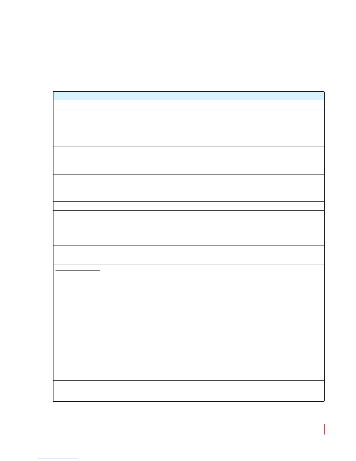
Chapter 6 Features and Specifications
Specifications
Specifications
Table 6–2 Specifications for the AMPx-S8 Series Monitors
Specification Value
Power Consumption 72 W max
AC Mains Input 100 to 240 VAC, 50 to 60 Hz
Analog Input Impedance 27K balanced, minimum
AES Input Configuration 110 balanced, 75 unbalanced
Analog Input Overload +24 dBu balanced
Analog Reference +8, +6, +4, or 0 dBu
Digital Reference -20, -18, or -9 dBFS
Meter Dynamics (AES Scale) VU and PPM
Level Meter Scale (standard) AES
AES Input Sampling Rate
D to A Converter
Peak Acoustic Output (at 2 ft.) 104 dB SPL
Acoustic Distortion
Response, 6th Octave
Distortion, Electrical <0.15% at any level below limit threshold
Hum and Noise, Analog Better than 68 dB below full output
Power Output
a
32 to 48 kHz, autoselected
24-bit low jitter
6% or less at worst case frequencies above 140 Hz
including cabinet resonance; typically < 1.5%
80Hz to 18 KHz ±5 dB
(-10 dB at 55 Hz, 21 kHz)
High Frequency
Low Frequency
6 W RMS (each channel)
14 W RMS
Converted Analog Out THD <0.008%
3.5” H x 19” W x 12.5” D
(89 mm x 483 mm x 317.5 mm)
2RU Model Chassis Dimensions
(Depth, including controls and knobs, is 14” [355.6
mm])
1.75” x 19” x 11”
(4.5 mm x 483 mm x 30 mm)
1RU Model Chassis Dimensions
(Depth, including controls and knobs, is 13.5”
[342.9 mm])
1RU: 13 lbs. (5.9 kg)
Weight
2RU: 18 lbs. (8.2 kg)
© 2011 Wohler Technologies, Inc. All rights reserved.
821030: AMPx-S8 Series User Guide
59
Page 70
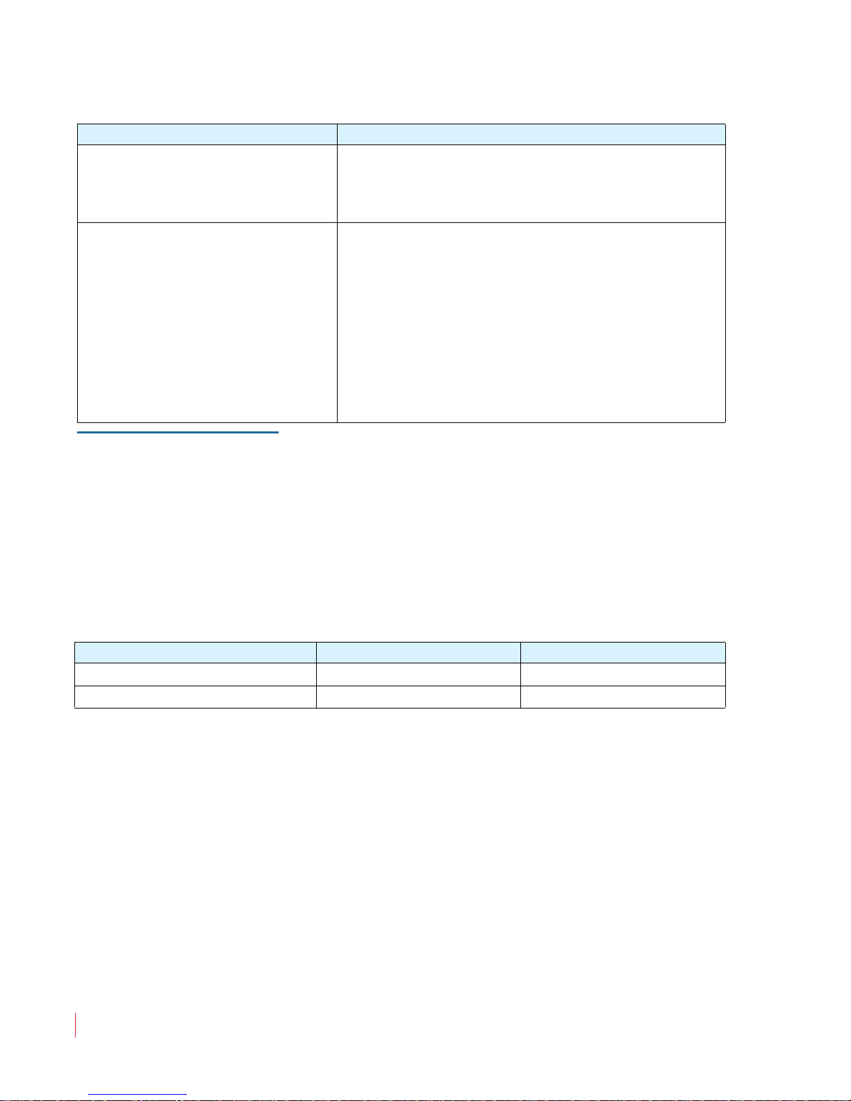
Chapter 6 Features and Specifications
Technical Functional Overview
Table 6–2 Specifications for the AMPx-S8 Series Monitors
Specification Value
• AES (D-Sub 25, 4 BNC)
Inputs
• 3G/HD/SD-SDI (2 BNC)
• Analog (D-Sub 25)
• Metered Analog (DB-25)
• 3G/HD/SD-SDI Re-Clocked (BNC)
• AES Unbalanced Out from SDI (HD-15)
Outputs
• (Optional) Balanced AES Out from SDI Input
(DB-25)
• Selected Downmix/Analog Out (Left and
Right, XLR-M)
• AES Bal In/Loop Out (DB-25)
a Other level meter scales are available at time of manufacture including BBC, DIN, and others.
Contact Wohler for more information concerning alternate scales.
Note:
All features and specifications are subject to improvement
without notice.
HD and 3G SDI signals require embedded audio phase data according
to SMPTE 299-2009.
Table 6–3 Size-Specific Specifications for the AMPx-E8 Series
Monitors
Specification AMP1s AMP2s
Rack Height 1RU 2RU
Level Meter Segments 26 segments 53 segements
Technical Functional Overview
Figure 6–1 on page 61 through Figure 6–3 on page 63 illustrate the
overall functionality of each of the AMPx-X8 models.
821030: AMPx-S8 Series User Guide
60
© 2011 Wohler Technologies, Inc. All rights reserved.
Page 71
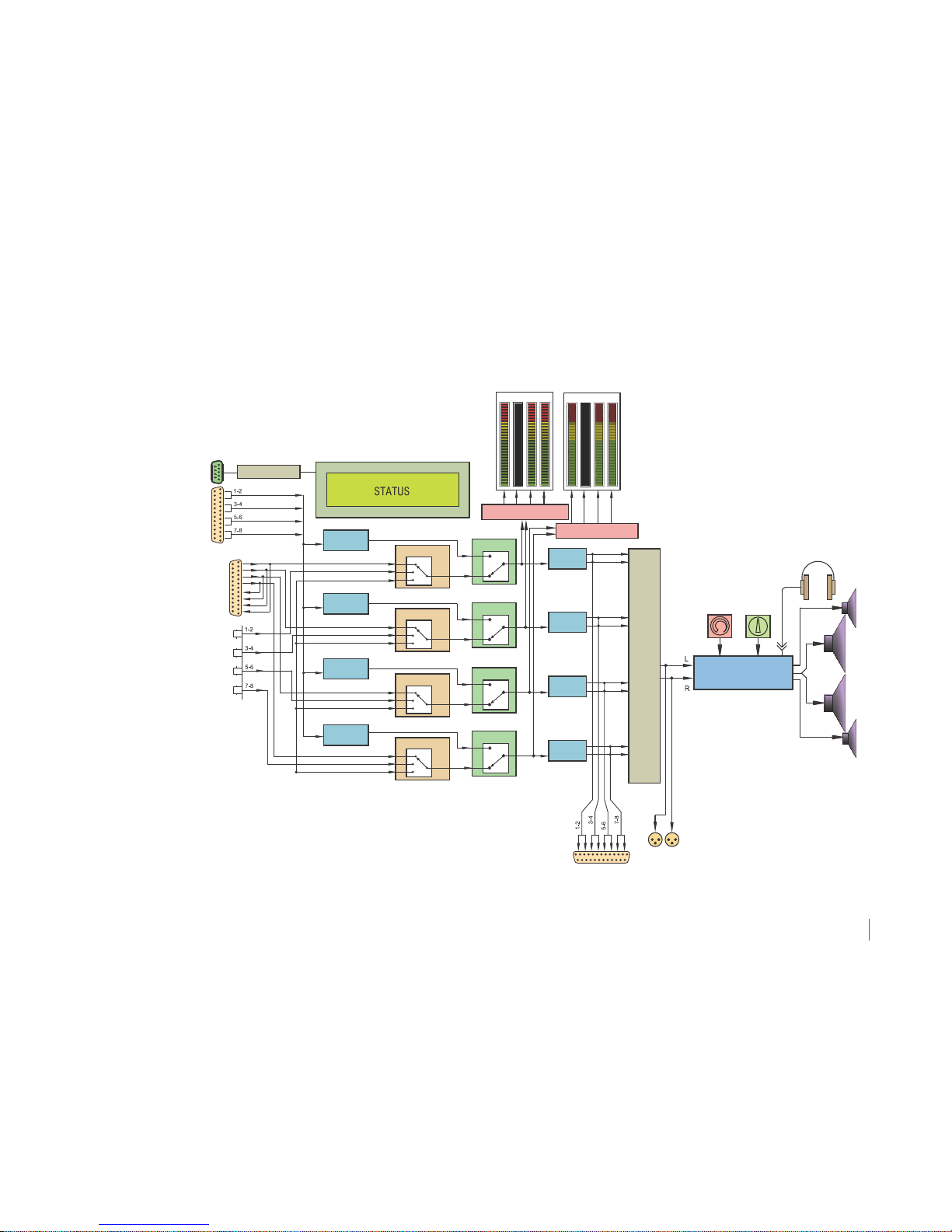
821030: AMPx-S8 Series User Guide
© 2011 Wohler Technologies, Inc. All rights reserved.
61
Chapter 6 Feat ures and Specifications
Technical Functional Overview
Figure 6–1 AMP1-S8DA Block Diagram
Balanced
Analog Inputs
(DB-25)
Unbalanced
AES/EBU
Inputs (BNC)
1-2
3-4
1-2
3-4
5-6
7-8
5-6
7-8
uP Control / U.I.
LCD Display
Group & Channel Switching Status
RS-232 A
1
2
5
6
3
4
7
8
Analog Out From
Selected Source
(Chan. 1-8)
Analog Matrix & Channel Summing with Front Panel Control
Balanced
AES Inputs
and Loopthrough
Outputs
(DB-25)
Balanced Digital In 3-4
Balanced Digital In 1-2
Balanced Digital In 5-6
Balanced Digital In 7-8
Unbalanced Digital In 7-8
Unbalanced Digital In 5-6
Unbalanced Digital In 3-4
Unbalanced Digital In 1-2
SDI In 1-2
SDI In 3-4
SDI In 7-8
SDI In 5-6
53-Segment
Hi-Res Level Meters
Selected/Downmix
Analog Out
From Selected
Source (Stereo)
L
R
Level Metering
1234
5678
Level Metering
Left
Speaker
Stereo Analog
Amplier
Volume
Balance
Woofer
Speaker
Right
Speaker
Headphone
Woofer
Speaker
Analog to
Digital
Analog to
Digital
Digital Input Select
1-2
3-4
5-6
7-8
1
2
3
D/A Select
A
D
Analog to
Digital
Digital to
Analog
Digital to
Analog
Digital to
Analog
Digital to
Analog
Digital Input Select
1
2
3
D/A Select
A
D
Analog to
Digital
Digital Input Select
1
2
3
D/A Select
A
D
Digital Input Select
1
2
3
D/A Select
A
D
Page 72
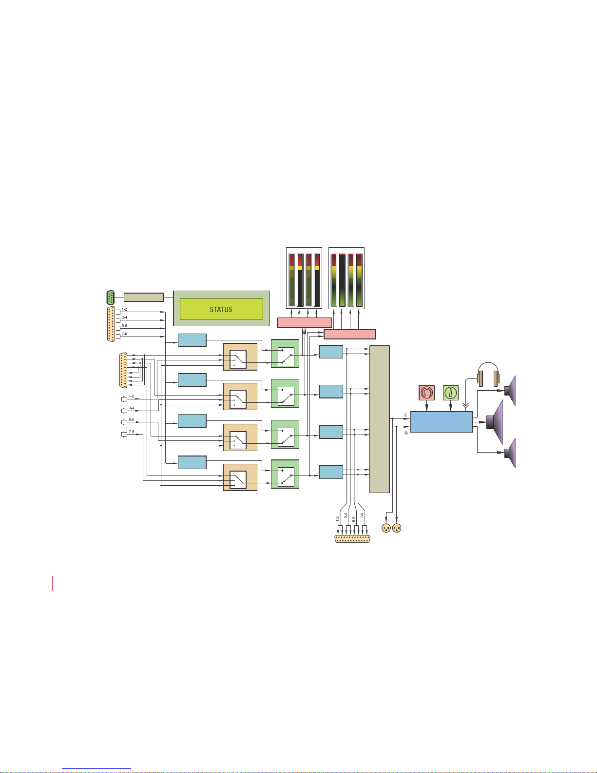
821030: AMPx-S8 Series User Guide
© 2011 Wohler Technologies, Inc. All rights reserved.
62
Chapter 6 Features and Specifications
Technical Functional Overview
Figure 6–2 AMP2-S8DA Block Diagram
Balanced
Analog Inputs
(DB-25)
Unbalanced
AES/EBU
Inputs (BNC)
1-2
3-4
1-2
3-4
5-6
7-8
5-6
7-8
uP Control / U.I.
LCD Display
Group & Channel Switching Status
RS-232 A
1
2
5
6
3
4
7
8
Analog Out From
Selected Source
(Chan. 1-8)
Analog Matrix & Channel Summing with Front Panel Control
Balanced
AES Inputs
and Loopthrough
Outputs
(DB-25)
Balanced Digital In 3-4
Balanced Digital In 1-2
Balanced Digital In 5-6
Balanced Digital In 7-8
Unbalanced Digital In 7-8
Unbalanced Digital In 5-6
Unbalanced Digital In 3-4
Unbalanced Digital In 1-2
SDI In 1-2
SDI In 3-4
SDI In 7-8
SDI In 5-6
Left
Speaker
Right
Speaker
Woofer
Speaker
Stereo Analog
Amplier
Volume
53-Segment
Hi-Res Level Meters
Balance
Headphone
Selected/Downmix
Analog Out
From Selected
Source (Stereo)
L
R
Level Metering
1234
5678
Level Metering
Analog to
Digital
Analog to
Digital
Digital Input Select
1-2
3-4
5-6
7-8
1
2
3
D/A Select
A
D
Analog to
Digital
Digital to
Analog
Digital to
Analog
Digital to
Analog
Digital to
Analog
Digital Input Select
1
2
3
D/A Select
A
D
Analog to
Digital
Digital Input Select
1
2
3
D/A Select
A
D
Digital Input Select
1
2
3
D/A Select
A
D
Page 73
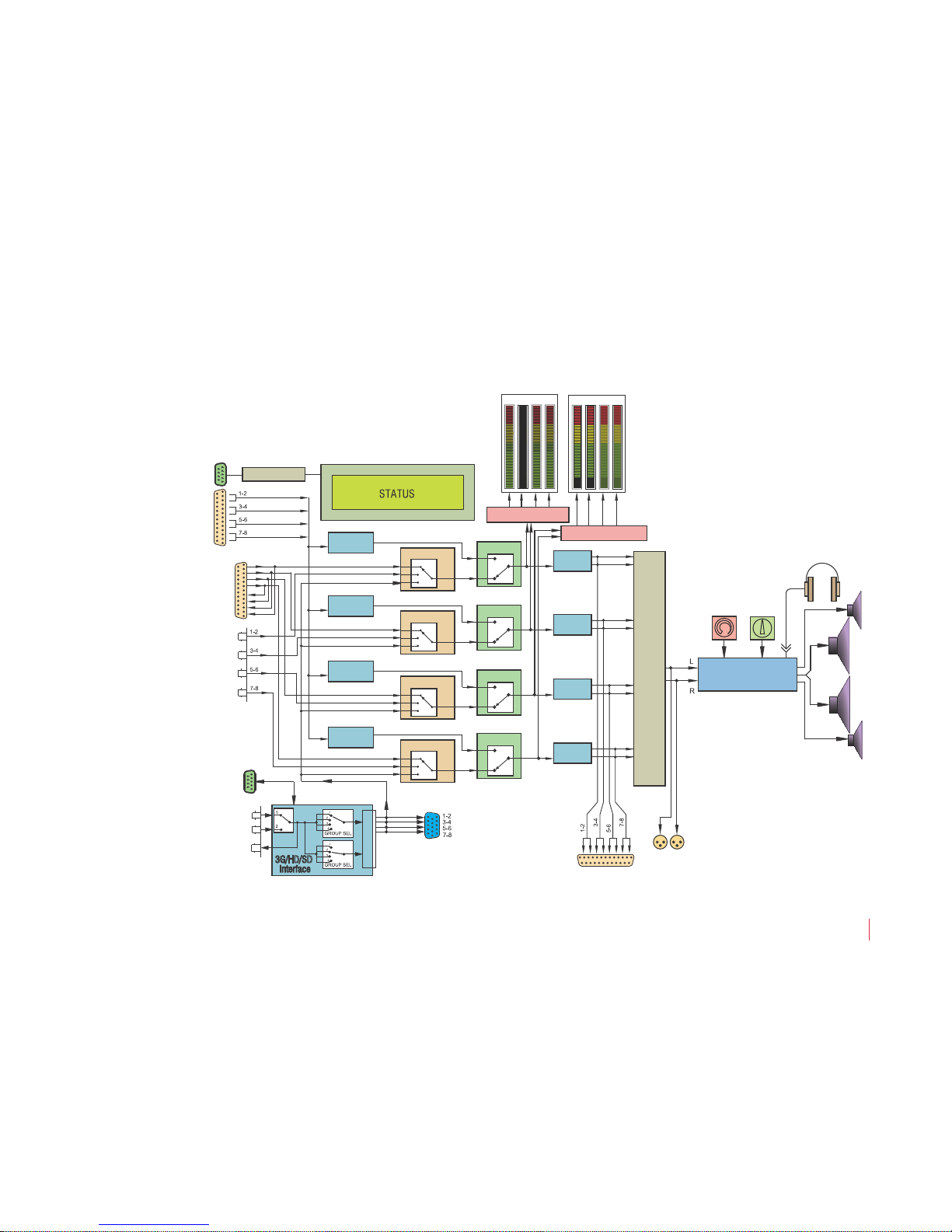
821030: AMPx-S8 Series User Guide
© 2011 Wohler Technologies, Inc. All rights reserved.
63
Chapter 6 Feat ures and Specifications
Technical Functional Overview
Figure 6–3 AMP1-S8MDA-3G Block Diagram
Balanced
Analog Inputs
(DB-25)
Unbalanced
AES/EBU
Inputs (BNC)
1-2
3-4
1-2
3-4
5-6
7-8
5-6
7-8
uP Control / U.I.
LCD Display
Group & Channel Switching Status
RS-232 A
1
2
5
6
3
4
7
8
Analog Out From
Selected Source
(Channels 1 to 8)
Analog Matrix & Channel Summing with Front Panel Control
Balanced
AES Inputs
and Loopthrough
Outputs
(DB-25)
Balanced Digital In 3-4
Balanced Digital In 1-2
Balanced Digital In 5-6
Balanced Digital In 7-8
Unbalanced Digital In 7-8
Unbalanced Digital In 5-6
Unbalanced Digital In 3-4
Unbalanced Digital In 1-2
SDI In 1-2
SDI In 3-4
SDI In 7-8
SDI In 5-6
Unbalanced
AES Output
from SDI
SDI to AES
Output
(Reclocked)
Input #1
3G/HD/SD-SDI Section
Input #2
Selected/Downmix
Analog Out from
Selected Source
(Stereo)
L
R
Level Metering
Level Metering
1234
5678
3G/HD/SD
Interface
RS-232 C
Left
Speaker
Stereo Analog
Amplifier
Volume
Balance
Woofer
Speaker
Right
Speaker
Headphone
Woofer
Speaker
Analog to
Digital
Analog to
Digital
Digital Input Select
1-2
3-4
5-6
7-8
1
2
3
D/A Select
A
D
Analog to
Digital
Digital to
Analog
Digital to
Analog
Digital to
Analog
Digital to
Analog
Digital Input Select
1
2
3
D/A Select
A
D
Analog to
Digital
Digital Input Select
1
2
3
D/A Select
A
D
Digital Input Select
1
2
3
D/A Select
A
D
Page 74
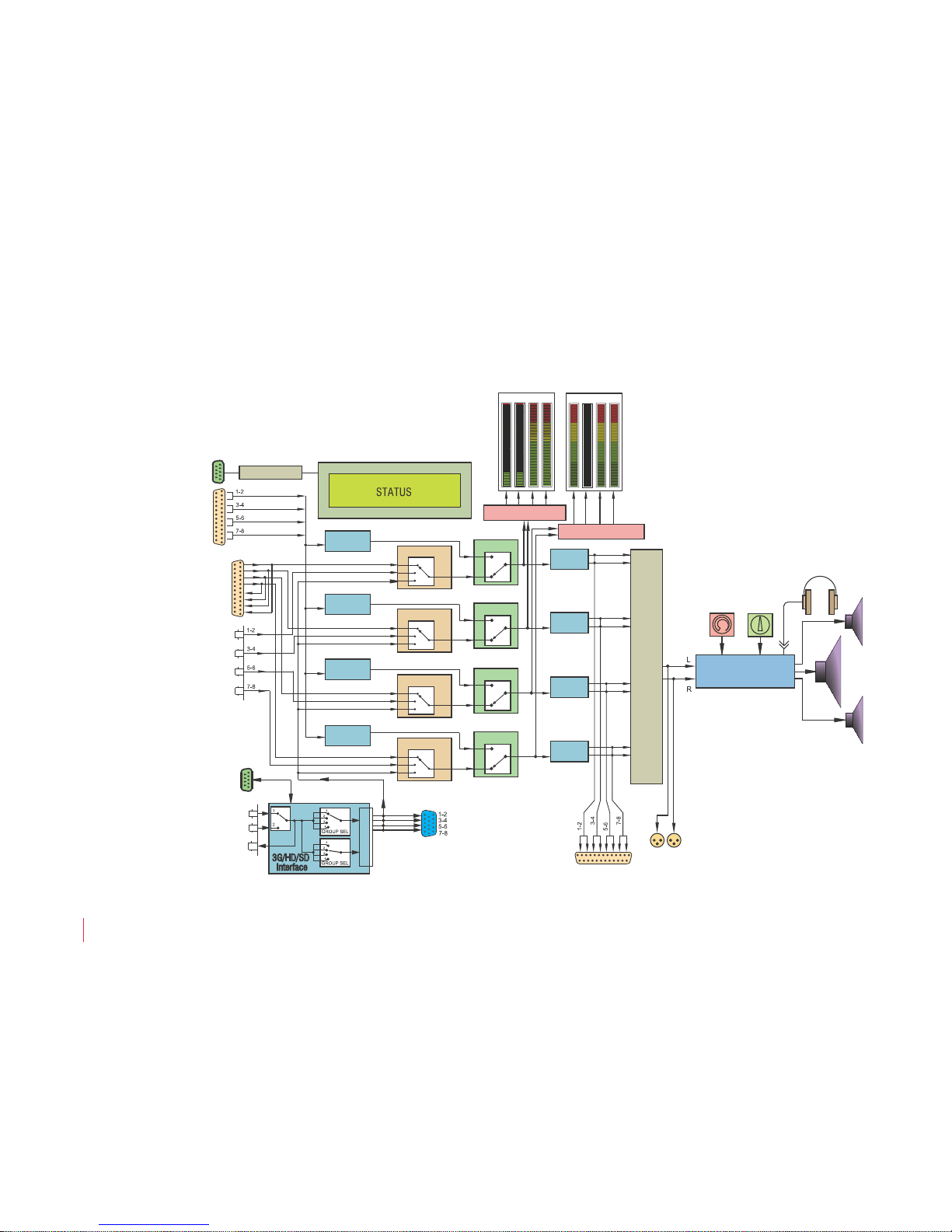
821030: AMPx-S8 Series User Guide
© 2011 Wohler Technologies, Inc. All rights reserved.
64
Chapter 6 Features and Specifications
Technical Functional Overview
Figure 6–4 AMP2-S8MDA-3G Block Diagram
Balanced
Analog Inputs
(DB-25)
Unbalanced
AES/EBU
Inputs (BNC)
1-2
3-4
1-2
3-4
5-6
7-8
5-6
7-8
uP Control / U.I.
LCD Display
Group & Channel Switching Status
RS-232 A
1
2
5
6
3
4
7
8
Analog Out From
Selected Source
(Channels 1 to 8)
Analog Matrix & Channel Summing with Front Panel Control
Balanced
AES Inputs
and Loopthrough
Outputs
(DB-25)
Balanced Digital In 3-4
Balanced Digital In 1-2
Balanced Digital In 5-6
Balanced Digital In 7-8
Unbalanced Digital In 7-8
Unbalanced Digital In 5-6
Unbalanced Digital In 3-4
Unbalanced Digital In 1-2
SDI In 1-2
SDI In 3-4
SDI In 7-8
SDI In 5-6
Unbalanced
AES Output
from SDI
SDI to AES
Output
(Reclocked)
Input #1
3G/HD/SD-SDI Section
Input #2
Left
Speaker
Right
Speaker
Woofer
Speaker
Stereo Analog
Amplifier
Volume
53-Segment
Hi-Res Level Meters
Balance
Headphone
Selected/Downmix
Analog Out from
Selected Source
(Stereo)
L
R
Level Metering
Level Metering
1234
5678
3G/HD/SD
Interface
RS-232 C
Analog to
Digital
Analog to
Digital
Digital Input Select
1-2
3-4
5-6
7-8
1
2
3
D/A Select
A
D
Analog to
Digital
Digital to
Analog
Digital to
Analog
Digital to
Analog
Digital to
Analog
Digital Input Select
1
2
3
D/A Select
A
D
Analog to
Digital
Digital Input Select
1
2
3
D/A Select
A
D
Digital Input Select
1
2
3
D/A Select
A
D
 Loading...