

Page 1

AMP1-8-M
1RU, 8-Channel, 3G/HD/SD-SDI Audio Monitor
User Guide
Software Release: V5.xx
Part Number 821815, Revision A
Page 2

© 2016 Wohler Technologies, Inc. All rights reserved.
This publication is protected by federal copyright law. No part of this publication may be copied or
distributed, stored in a retrieval system, or translated into any human or computer language in any
form or by any means electronic, mechanical, manual, magnetic, or otherwise, or disclosed to third
parties without the express written permission of Wohler Technologies, Inc.
Reproduction
Licensed users and authorized distributors of Wohler Technologies, Inc. products may copy this
document for use with Wohler Technologies., Inc. products provided that the copyright notice above
is included in all reproductions.
Customer Support
Wohler Technologies, Inc.
31055 Huntwood Avenue
Hayward, CA 94544 www.wohler.com
Phone: 510-870-0810
FAX: 510-870-0811
US Toll Free: 1-888-596-4537 (1-888-5-WOHLER)
Web: www.wohler.com Sales: [email protected]
Support: [email protected]
Disclaimers
Even though Wohler Technologies, Inc. has tested its equipment and software, and reviewed the
documentation, Wohler Technologies, Inc. makes no warranty or representation, either express or
implied, with respect to software, documentation, their quality, performance, merchantability, or
fitness for a particular purpose.
In no event will Wohler Technologies, Inc. be liable for direct, indirect, special, incidental, or
consequential damages resulting from any defect in the hardware, software, or its documentation,
even if advised of the possibility of such damages.
Some states do not allow the exclusion or limitation for incidental or consequential damages, so the
above exclusion or limitation may not apply to you.
Printing
This document looks best when printed on a color printer since some images may be indistinct when
printed on a black and white printer.
PDF
All text strings appearing in this shade of blue are hyperlinks.
Other Technologies and Products
Google Chrome is a registered trademark of Alphabet Inc. Microsoft Windows and Internet Explorer
are registered trademarks of Microsoft Corporation.
Last Update
August 7, 2016
Page2
Page 3

TABLE OF CONTENTS
Contents
User Guide ........................................................................................ 1
TABLE OF CONTENTS .......................................................................... 3
Contents ....................................................................................................... 3
CHAPTER 1: Quick Start ....................................................................... 5
Introduction .................................................................................................. 5
Overview ............................................................................................ 5
Safety .......................................................................................................... 5
Instructions ......................................................................................... 5
Safety Symbols .................................................................................... 6
Mounting ............................................................................................. 6
Heat Dissipation ................................................................................... 6
Sympathetic Vibration ........................................................................... 6
Mechanical Bracing ............................................................................... 7
Electrical Interference ........................................................................... 7
Power ................................................................................................. 7
Compliance ................................................................................................... 7
FCC .................................................................................................... 7
ICES-003 ............................................................................................ 7
Front Panel .................................................................................................... 8
Rear Panel .................................................................................................... 9
CHAPTER 2: Operation ....................................................................... 10
Introduction ................................................................................................ 10
Main Screen ................................................................................................ 10
USB Port Functionality .................................................................................. 12
Getting a Configuration from the Flash Drive .......................................... 13
Save System Configuration to Flash Drive .............................................. 13
Update Menu ..................................................................................... 14
CHAPTER 3 - Internal Menu System ..................................................... 15
Introduction ................................................................................................ 15
Menu Navigation Overview ............................................................................ 15
Audio Menu ................................................................................................. 16
Speaker Control Options Menu ....................................................................... 17
Select and Detect Options Menu ..................................................................... 18
Screen and Phase Options Menu ..................................................................... 20
Meter Type and Reference Menu ..................................................................... 21
Meter Segment Menu .................................................................................... 23
Version and Ethernet Menu ............................................................................ 24
Page3
Page 4

CHAPTER 4 - Features and Specifications .............................................. 26
Introduction ................................................................................................ 26
Features ..................................................................................................... 26
Compliance ................................................................................................. 27
Specifications .............................................................................................. 27
Audio Formats ............................................................................................. 28
Technical Functional Overview ........................................................................ 29
APPENDIX A: Upgrading the AMP1-8-M Using a USB Flash Drive .............. 30
Introduction ................................................................................................ 30
Upgrading the Software Using a USB Flash Drive .............................................. 30
Page4
Page 5

CHAPTER 1: Quick Start
Introduction
Overview
The AMP1-8-M is a 1RU, 8-channel, 3G/HD/SD-SDI audio monitor. This unit comes
with two 2.4” graphics screens that work together to display 8 channels of audio
level metering. You can both visibly and audibly monitor either the first four pairs
(Channels 1 thru 8) or the second four pairs (Channels 9 thru 16) of the selected
3G/HD/SD-SDI input signal. The AMP1-8-M is small, low-cost, reliable and simple to
operate. Configuration is simple and you can easily copy any configuration to other
AMP1-8-M units.
Note that very little configuration should be necessary. We have already configured
the unit to the most commonly requested settings. However, should you need to
change these settings, you can access the unit through the front panel menu
system.
Safety
Instructions
1. Read, keep, and follow all of these instructions; heed all warnings.
2. Do not use this equipment near water.
3. Use only a dry cloth to clean the equipment.
4. Do not block any ventilation openings.
5. Do not install near any heat source such as a radiator, heat register, amplifier, or
stove.
6. Do not attempt to plug the unit into a two-blade outlet (with only two prongs of
equal width).
Important:
7. Protect the power cord from being walked on or pinched, particularly at plug
connections on the equipment and at the socket.
By design, this monitor will only plug into a three-prong outlet for
your safety. If the plug does not fit into the outlet, contact an
electrician to replace the obsolete outlet.
8. Use only the attachments/accessories specified by the manufacturer.
9. Unplug the equipment during lightning storms or when unused for long periods
of time.
10. Refer all servicing to qualified service personnel. Servicing will be required
Page5
Page 6
0”
under all of the following conditions:
a. The equipment has been damaged in any way, such as when the power-
supply cord or plug is damaged.
b. Liquid had been spilled or objects have fallen onto the equipment.
c. The equipment has been exposed to rain or moisture.
d. The equipment does not operate normally.
e. The equipment has been dropped.
Safety Symbols
The symbol to the left warns of electric shock hazard inside the unit.
Disconnect the power cord before removing access panels when installing
upgrades. Only qualified service personnel are to operate the equipment
with covers removed, and are to exercise caution to avoid personal injury.
Mounting
The unit is designed for a standard 19" rack. Install it at ear/eye level for best high
frequency response and visual observation of the display screens. Please adhere to
the following clearances:
Clearance
Heat Dissipation
The ambient temperature inside the mounting enclosure should not exceed 40°
Celsius (104° Fahrenheit). Adjacent devices can be rack mounted (or stacked) in
proximity to the unit if this temperature is not exceeded. Otherwise, allow a 1RU
(1.75”/44.45mm) space above and below the unit for air circulation.
Important:
Surface
24” Front
3” Rear
2” Sides
1.75” Top and Bottom (if either radiates heat)
Top and Bottom (if no heat)
To reduce noise, the monitor does not have any fans. As a result, the
heat generated by the class D power amplifiers, power supplies, and
other components is vented by slots in the sides and back of the unit.
Therefore, as a safety precaution, you must allow proper ventilation
on these surfaces.
Sympathetic Vibration
Sympathetic vibration from other equipment (cables, etc.,) in the rack may be
Page6
Page 7

serious enough to interfere with the sound quality of the unit. If you experience
sympathetic vibrations, use thin card stock, felt, foam, or weather-stripping
between the vibrating surfaces. Tie loose cables securely with cable ties.
Mechanical Bracing
The 1RU chassis is securely attached to the front panel. In addition, the chassis has
mounting tabs through which you attach it to the rack rail. This feature will reduce
or eliminate rear bracing requirements in many mobile/portable applications. The
weight of internal components is distributed fairly evenly around the unit.
Electrical Interference
Be careful to avoid mismatched cable types and other similar causes of undesired
reflections in digital signal systems. If severe enough, such reflections can result in
corruption of the digital data stream. As with any audio equipment, maximum
immunity from electrical interference requires the use of shielded cable; however,
satisfactory results can sometimes be obtained without it. The internal circuitry
ground is connected to the chassis.
Power
The unit comes with a standard internal power supply and connects an A/C mains
power source (60W, 100 to 240 VAC, ±10%, 50/60Hz) through the IEC connector
provided on the rear panel of the unit.
When the mains plug or appliance coupler is used as the disconnect device, the
disconnect device should remain operable.
Compliance
FCC
This equipment has been tested and found to comply with the limits for a Class A
digital device, pursuant to part 15 of the FCC Rules. These limits are designed to
provide reasonable protection against harmful interference when the equipment is
operated in a commercial environment. This equipment generates, uses, and can
radiate radio frequency energy and, if not installed and used in accordance with the
instruction manual, may cause harmful interference to radio communications.
Operation of this equipment in a residential area is likely to cause harmful
interference, in which case the user will be required to correct the interference at
their own expense.
ICES-003
This Class A digital apparatus complies with Canadian ICES-003.
Cet appareil numérique de la classe A est conforme à la norme NMB-003 du
Canada.
Page7
Page 8
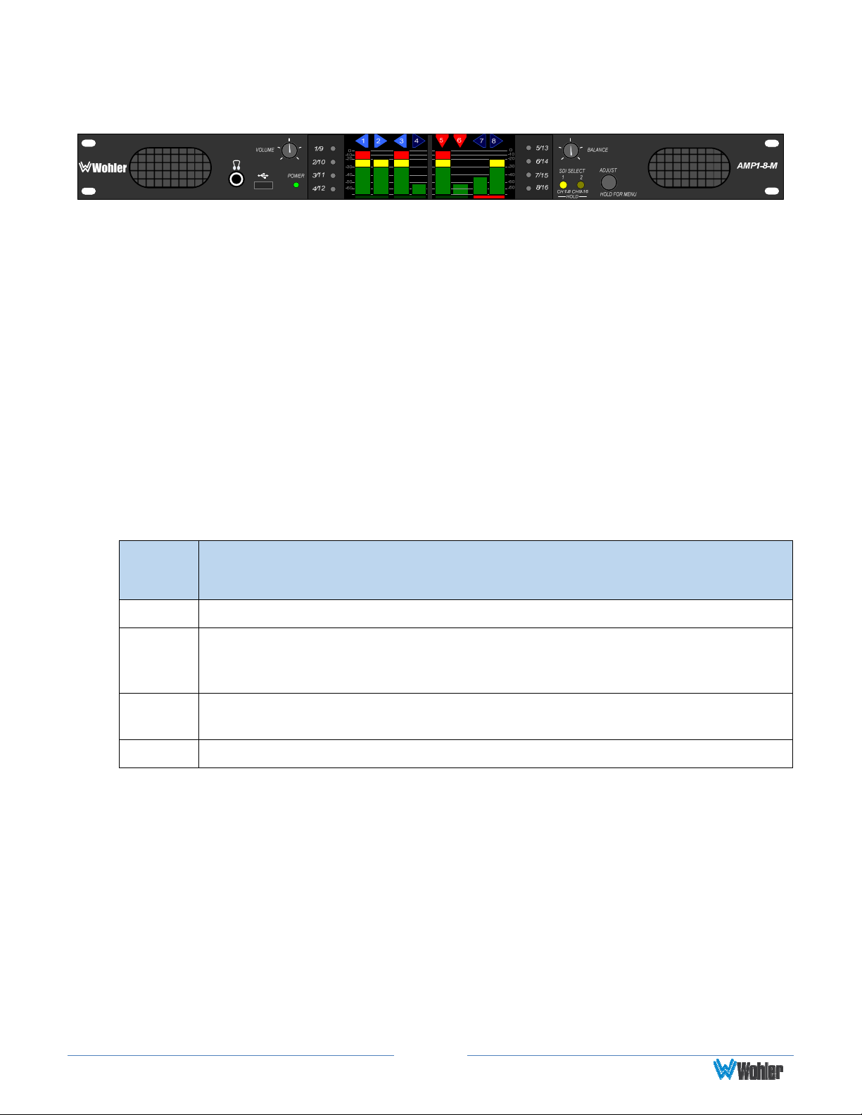
Front Panel
1. Speakers: Audio monitoring is achieved through the use of Class D amplifiers
driving two (left/right) wide range speakers.
2. Headphone Jack (1/4”): A 1/4" jack for an optional headphone is provided on
the front panel.
3. USB 2.0 Port: This USB Type A connector allows you to use a flash drive (not
supplied) to update the unit’s firmware.
4. Volume: The left knob controls the Volume of the internal speakers,
headphones, and optionally of the rear panel balanced analog outputs. This
control can be set so that it only controls the Left Volume.
5. Power Indicator: This tri-color LED indicates power and basic status
information. See Table 1–1 below.
Figure 1–1: Front Panel Layout
Table 1–1: Power Color / Indication Descriptions
LED
Color
Green The AMP1-8-M is functioning properly.
When the LED flashes green or yellow followed by a series of red flashes,
Red
Yellow
Off The AMP1-8-M is not receiving AC power.
6. Metering: These screens work together to display level meter bar graphs and
configuration menus.
7. Channel Select Buttons: These eight buttons allow you to select single
channels to be monitored. They operate as configured in the internal menu
system.
each flash sequence indicates an error code. Try restarting the unit, and
if the problem persists, contact Wohler Technical Support.
The LED is also a solid yellow when the AMP1-8-M is first starting up.
The LED blinks yellow when a firmware update is in progress.
Description
8. Balance: The right knob adjusts the Balance between th e speakers and
optionally between the rear panel balanced analog outputs. This control can be
configured so that it only controls the Right Volume. Refer to the Speaker
Control Options Menu described in Chapter 3.
9. SDI Selection: These buttons have two functions:
a. Press and release either of these LED buttons to select one of the two SDI
Page8
Page 9
inputs. Note that SDI 1 is selected by default whenever the AMP1-8-M is
powered up, or
b. Press and hold either of these LED button for three seconds to switch
between monitoring channels 1 – 8 or channels 9 – 16 for the selected
SDI source.
10.Adjust: Pressing and holding this button for approximately three seconds opens
the menu system you may use to customize the operation of the AMP1-8-M.
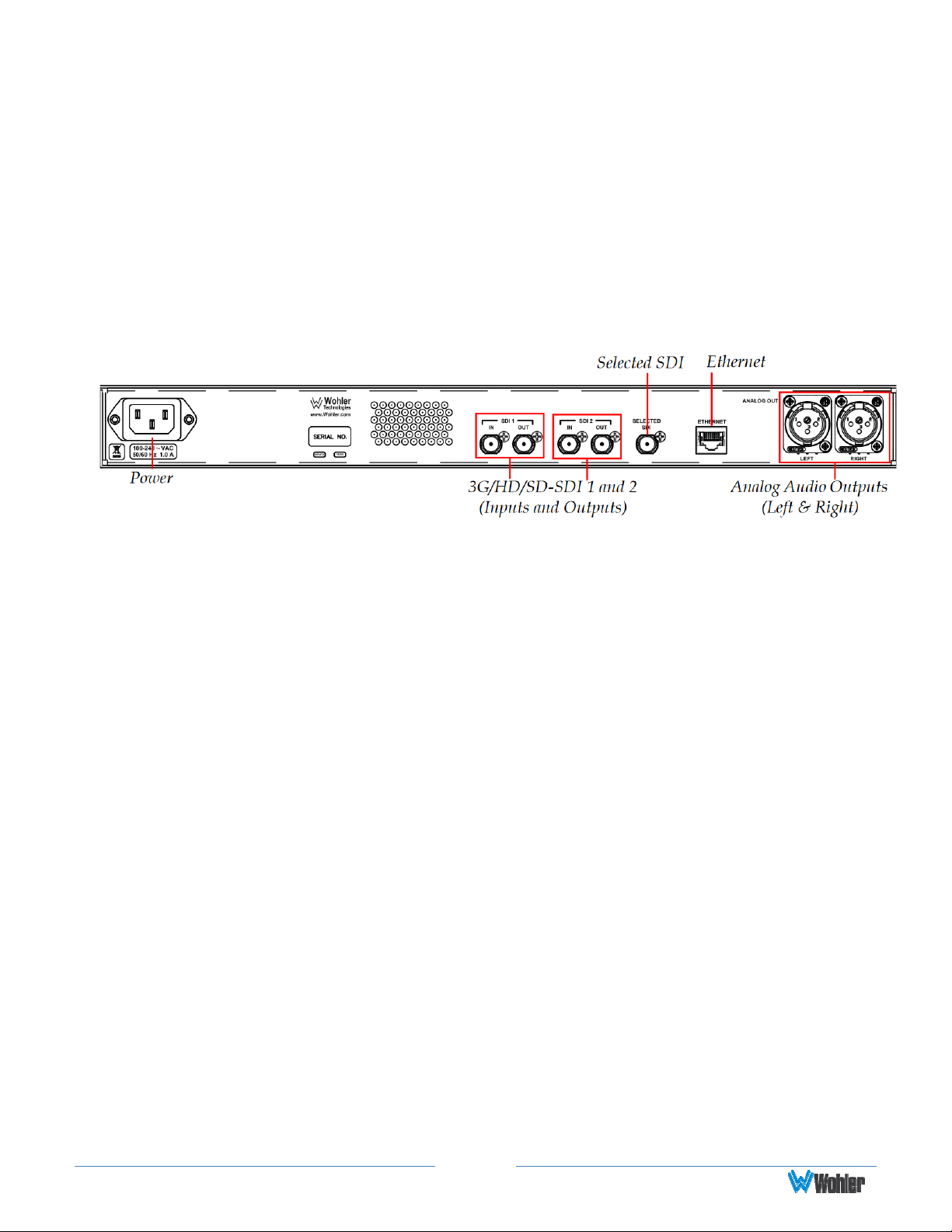
Rear Panel
Figure 1–2: Rear Panel Layout
1. Power: The AMP1-8-M uses a standard IEC power cord for the 100 to 240 VAC
±10%, 50/60 Hz power connection.
2. 3G/HD/SD-SDI Inputs: These two BNC connectors accept the 3G/HD/SD-SDI
input signals.
3. 3G/HD/SD-SDI Outputs: These BNC connectors output regenerated replicas
of the two 3G/HD/SD-SDI input signals.
4. Selected 3G/HD/SD-SDI Re-Clocked Output: This BNC connector re-clocks
the selected 3G/HD/SD-SDI input signal.
5. Ethernet: The AMP1-8-M does not currently use the Ethernet port except during
factory programming. For normal operation, the port may be connected to a LAN
or disconnected. In future releases, Wohler may or may not release remote
control software for this unit, such as is used in the AMP1-16-M.
6. Analog Outputs: These XLR connectors provide two channels of balanced
analog outputs. The source of these signals is the mix of audio monitored by the
internal speakers.
Page9
Page 10
CHAPTER 2: Operation
Introduction
This chapter describes how to operate the AMP1-8-M.
Main Screen
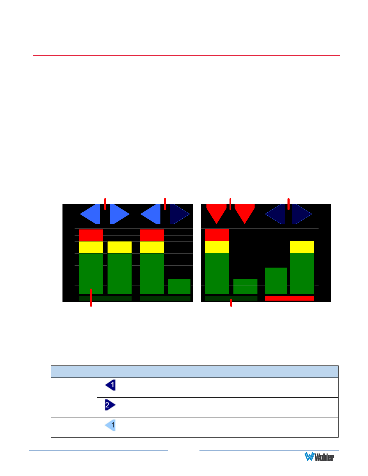
After powering up the AMP1-8-M and connecting an SDI input, you should see the
Main Screen, which will be similar to the one shown in Figure 2–1 below.
Fig 2–1: Main Screen
Speaker Indicators
(Left and Right)
1 2
0
0
-10
-10
-20
-20
-30
-30
-40
-40
-50
-50
-60
-60
Level Meters Phase Indicators
Speaker Indicators
(Left Selected, Right Muted)
3 4 7 8
Speaker Indicators
(Bitstream)
5
6
Speaker Indicators – No
Audio (Left and Right)
1. Speaker Indicators: The indicators above each meter identify the channel
number and the status of the channel.
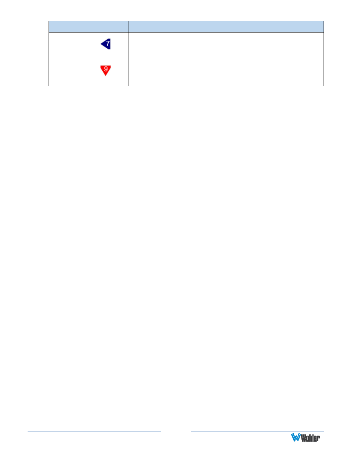
Table 2-1: Channel Icon Descriptions
0
-10
-20
-30
-40
-50
-60
Attribute Symbol Description Meaning
Icon
Shape
Icon Color
Left Pointing Blue
Triangle
Right Pointing Blue
Triangle
Light Blue Triangle
or Square
Page10
Channel Configured to sounds in
the left speaker
Channel configured to sound in the
right speaker
Channel is selected by the Channel
Select buttons and can be heard
Page 11
Attribute Symbol Description Meaning
Dark Blue Triangle
or Square
Downward Pointing
Red Triangle
Channel is not selected by the
Channel Select buttons and cannot
be heard
Channel contains a bitstream
instead of audio and cannot be
heard
2. Level Meters: The selected eight channels are metered.
3. Channel Selection: There are several ways to select channels for listening.
The unit can be configured to play all channels but solo selected channels, or
it may be configured to mute all channels, but play only selected channels.
Please refer to the Select and Detect Options Menu in Chapter 3 for
further information.
4. Adjust the Volume and Balance controls as necessary.
5. Phase Indicators: When any of these indicators are red, they indicate that
the odd/even pair is out of phase. Green indicates in phase. Refer to the
Options Menu in Chapter 3 for more information.
Page11
Page 12
USB Port Functionality
You can copy configuration files to and from your unit by using a flash drive
connected to the USB port.
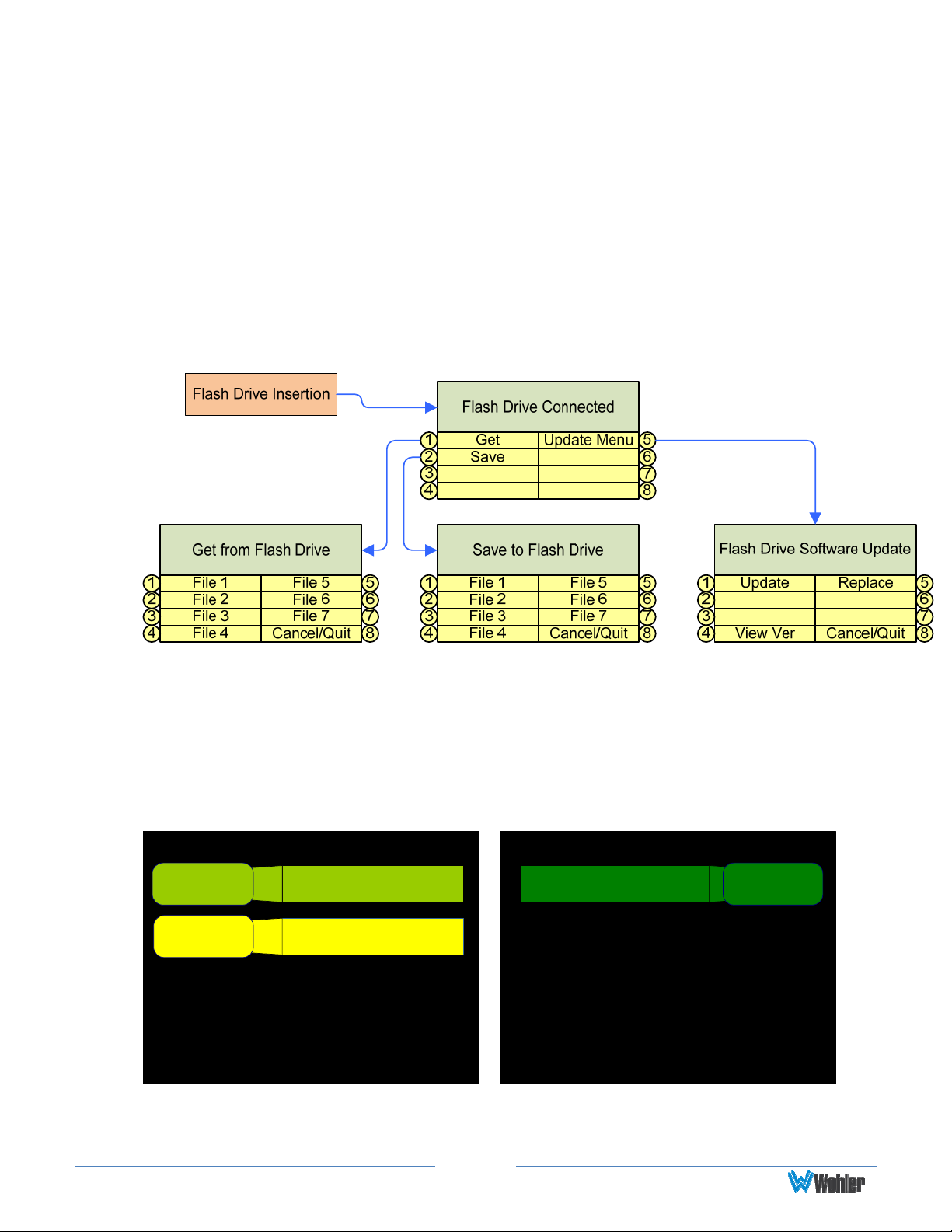
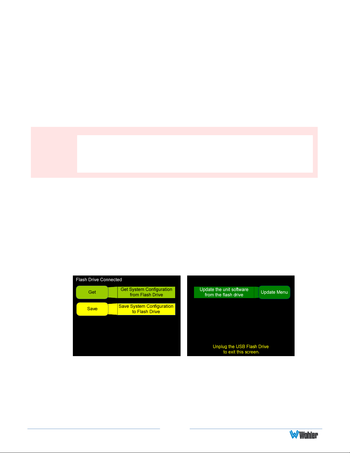
Immediately after connecting the flash drive to your AMP1-8-M, the Flash Drive
Connected screen displays (interrupting any current functions except an Ethernet
connection) as shown in Figure 2-3: below. The menu flow for the USB menu set is
shown immediately below in Figure 2-2. The Update Menu button will only appear
if the USB drive contains programming files. Refer to Appendix A.
Figure 2–2: Flash Drive Configurations Screen
Figure 2–3: Flash Drive Configurations Screen
Flash Drive Connected
Get
Save
Get System Configuration
from Flash Drive
Save System Configuration
to Flash Drive
Update the unit software
from the flash drive
Unplug the USB Flash Drive
to exit this screen.
Update Menu
Note: All configuration files end in the .wcfg extension.
Page12
Page 13
Getting a Configuration from the Flash Drive
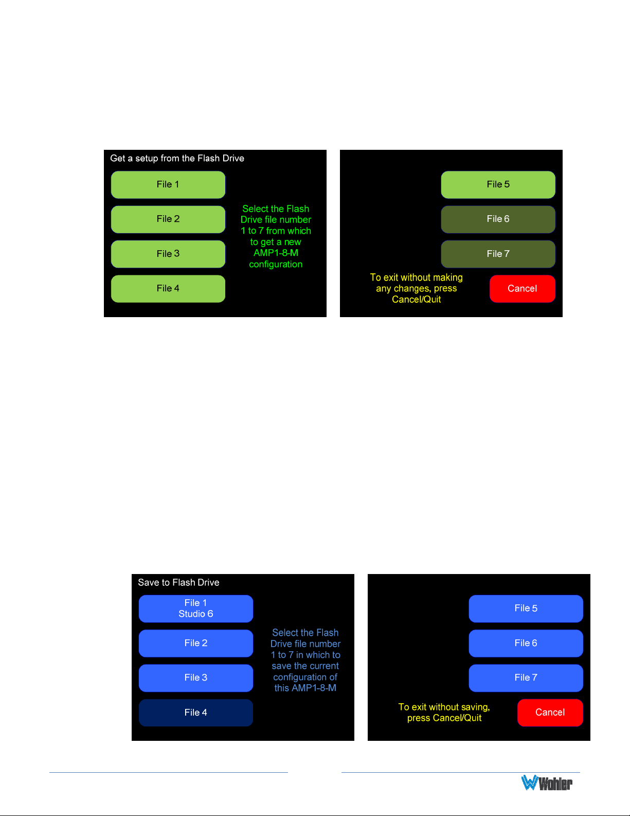
1. To load a configuration file to the AMP1-8-M from your flash drive, press Get.
The Get a setup from the Flash Drive screen will display as shown in
Figure 2–4 below.
Figure 2–4: Get a Setup from the Flash Drive Screen
2. Using one of the bright green choices, press the file number (File 1 through
File 7) of the file you want to copy from your flash drive. Once the copy
process completes, the Flash Drive Connected screen re-displays.
Note: The configuration takes effect immediately when you press the File
button.
3. Remove the flash drive from the USB port.
Save System Configuration to Flash Drive
1. To copy a file to the flash drive from the AMP1-8-M, press Save from the
Flash Drive Connected screen. The Save to Flash Drive screen will display
as shown in
are already occupied with data.
Figure 2–5. The lighter color buttons indicate file numbers that
Figure 2–5: Save to Flash Drive Screen
Page13
Page 14

2. Press the file number (File 1 through File 7) of the file you want to copy
from your flash drive. Once the copy process completes, the
Connected
screen re-displays.
Flash Drive
3. Remove the flash drive from the USB port.
Update Menu
This button only appears if the inserted flash drive contains a software update files.
Press this button to proceed to the software updating menu. Refer to Appendix A to
add a software update to a flash drive.
Page14
Page 15
CHAPTER 3 - Internal Menu System
Introduction
This chapter provides an in-dep th description of the menus and their respective
options and functions.
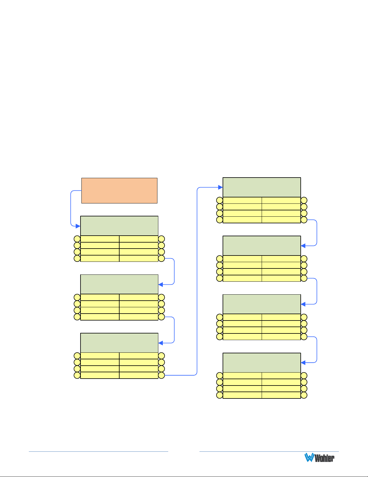
Menu Navigation Overview
You can launch the menu system by pressing and holding the Adjust encoder for at
least three seconds. Within any menu, pressing the Adjust encoder for at least
three seconds exits the menu system. Navigate the menu tree with the
Next buttons at the bottom of each screen.
Figure 3–1: Menu Tree
Back and
Press ADJUST Encoder for
3 Seconds to Enter or Exit
Menus.
Audio Menu
Never Mute1
Mute w/ Phones2
Always Mute3
Back4
Speaker Control Options
Menu
Volume Controls1
2
Set Tone Flat3
Back4
Select and Detect Options
Menu
No Chans Select1
Channel Select2
3
Back4
Fixed
Vol/Bal
Next 8
Treble
Bass
Low Cut
Next 8
Dolby Detect
Non-PCM Detect
Audio Delay
Next 8
Screen and Phase Options
Menu
1 Screen Bright
2
Screen Saver3
Back4
5
6
7
5
6
7
5
6
7
Meter Type & Reference
Scale1
Float2
Bar3
Back4
Meter Segment Options
Upper Seg1
Middle Seg2
Set Default3
4
Version & Ethernet Menu
1
2
Factory Default3
Back4
Phase Select 5
Next 8
Menu
Reference 5
Next 8
Menu
Upper Color 5
Middle Color 6
Lower Color 7
Next 8Back
Set 5
Ad Mode DHCP 6
Connect LAN 7
Finished 8
6
7
6
7
Page15
Page 16
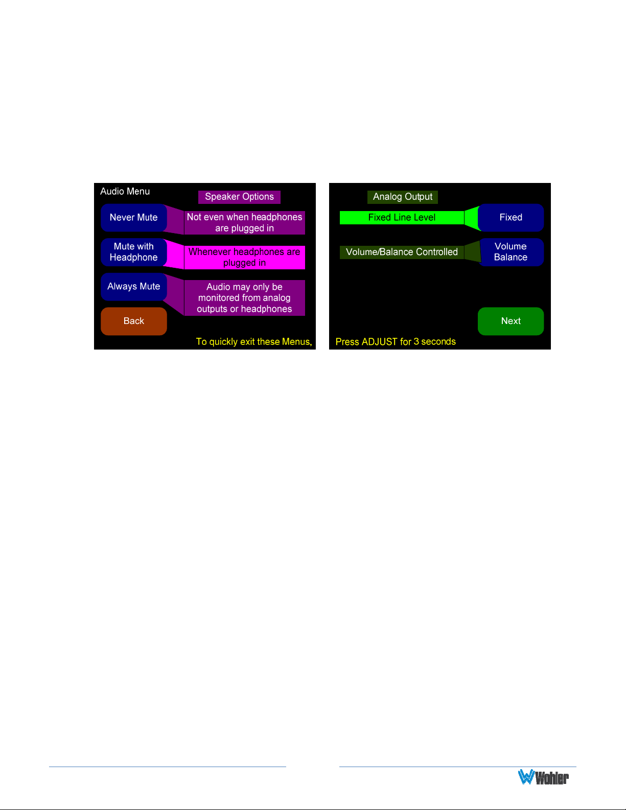
Audio Menu
This menu allows adjustment of various audio related settings. Buttons 1, 2, and 3
together form a Speaker Mute selector. The default Speaker Mute is Mute with
Headphone. Buttons 5 and 6 together form an Analog Output selector. The
standard Analog Output is Fixed Line Level.
Figure 3–2: Audio Menu
1. Never Mute: Pressing this button selects the option that the internal
speakers will not mute when headphones are plugged into the headphone
jack.
2. Mute with Headphone: Pressing this button selects the option that the
internal speakers will mute when headphones are plugged into the
headphone jack. This is the default setting.
3. Always Mute: Pressing this button selects the option that the internal
speakers will always be muted. This setting can be convenient to use when
monitoring is always done through the analog outputs with external
amplifiers and speakers.
4. Fixed: Pressing this button fixes the line level of the analog outputs as they
are in the SDI signal, where -20 dBFS = +4 dBu (± 1 dB). This is the default
setting.
5. Volume/Balance: Pressing this button enables the Volume and Balance
controls to affect the analog outputs. This setting can be convenient to use
when monitoring is always done through the analog outputs with external
amplifiers and speakers.
Note: If the Analog Output is set to Volume/Balance Controlled and the
Speaker Mute is set to Always, then plugging in the headphones will
cause the analog outputs to mute.
Page16
Page 17
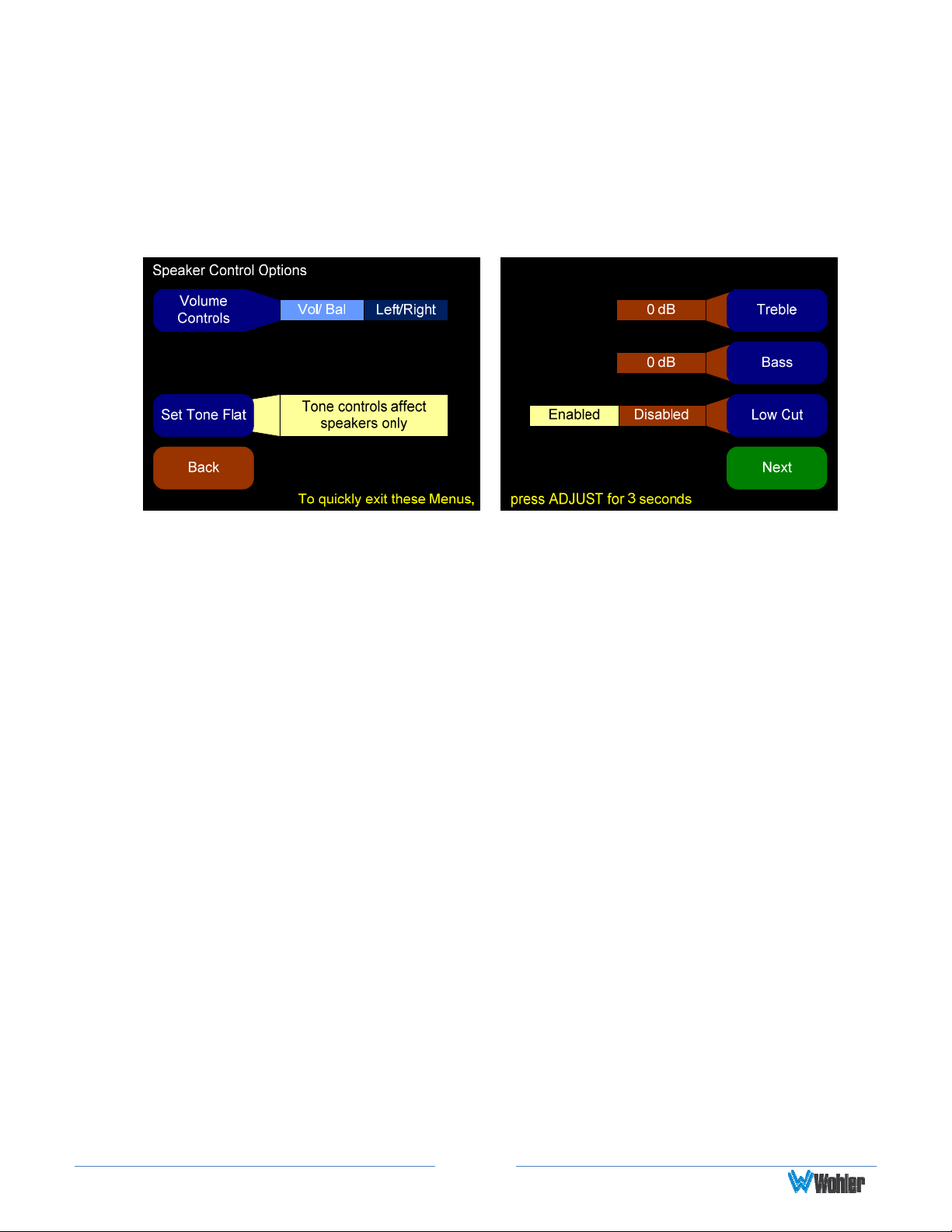
Speaker Control Options Menu
The Speaker Control Options menu allows configuration of the Volume and
Balance control knobs for different functions and provides tone controls for the
internal loudspeakers.
Figure 3–3: Speaker Control Options Menu
1. Volume Controls: You can use this option to change the master volume and
the balance knob to become Left Volume and Right Volume controls.
2. Set Tone Flat: Selecting Flat gives the flattest acoustic response possible
from the internal speakers.
3. Bass and Treble options are provided for customer tuning of the speaker
sound to fit your needs. Select the menu button and use the Adjust rotary
encoder to adjust to the desired level.
Lowering Bass will unmask midrange band sounds, while increasing Bass
will make the sound “fatter”.
Lowering Treble compensates for high frequency pre-emphasis or
removes sibilant effects. Increasing Treble will add “sizzle” to the sound
and bring high-pitched sounds out of the mix.
4. Low Cut: This option is provided for cases where unusually deep content
produces audible distortion.
Page17
Page 18
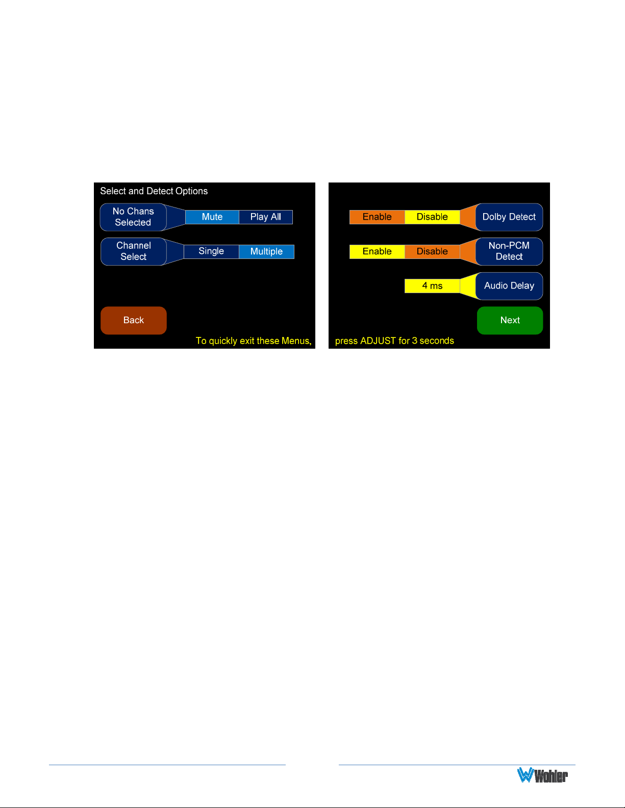
Select and Detect Options Menu
This Select and Detect Options menu allows adjustment of how channel
selections affect the muting or summing of other channels, how to handle Dolby
detection, and how to adjust audio delay in conjunction with other monitoring
equipment for issues of lip-syncing.
Figure 3–4: Select and Detect Options Menu
1. No Channels Selected: This control determines what happens when no
channels are selected in the main screen.
a. Mute means the unit will not play any of the channels when none are
selected. Use this option if you typically only want to hear one or two
channels at a time.
b. Play All means the unit will unmute, mix, and play all the channels in
the speakers when none are selected. Use this option if you usually
want to hear all the channels and only occasionally “solo” one or more
channels.
2. Channel Select: Set this control to determine how the select buttons work
in the main screen.
a. Single – Use his option if you only want to hear one channel at a time.
Pressing a select will cancel all other selects.
For example, if channel 1 is selected, and you press channel 3,
channel 1 will be de-selected, and channel 3 will be selected. If you
press the channel 3 select again, no channel will be selected, and what
sounds in the speakers will be determined by the No Chans Selected
control
b. Multiple – Use this option if you want to hear multiple channels at one
time. Pressing a select will not cancel all other selects.
For example, pressing selects 1-6 will result in channels 1-6 being
selected, and all 6 channels will sound in the speakers. Pressing the
select key for channel 1 again will de-selected channel 1, and mute it.
Page18
Page 19

3. Dolby Detect: Enabling Dolby Detect means an incoming digital stream is
monitored for certain keywords called "Pa Headers." This method of
detecting Dolby streams is very effective, unless the stream has been altered
since being created. Alterations such as volume control, dither, and samplerate conversion will also scramble the Pa headers, making this detection
method unreliable. For Dolby Pa header detection, the minimum
recommended delay is 42 milliseconds. Longer delays will prevent more
clicks and pops during switches.
4. Non-PCM Detect: Enabling this Dolby detection method means the channel
status bits are examined to determine if they indicate the stream is nonaudio. Unlike Pa detection, these bits are not affected by audio
manipulations. However, not all equipment passes or sets this bit correctly,
which may result in false detection or failure to detect.
5. Audio Delay: This will set the delay from the inputs to all outputs. This is
mainly used to "lip-sync" audio produced by this monitor with video monitors
which may have a few frames of delay from video signal processing
algorithms. Adding delay also gives this monitor time to detect and mute
Dolby bitstreams. Thus, longer delays will result in fewer (or no) undesirable
noises when signals suddenly change from PCM encoding to Dolby encoding.
Page19
Page 20
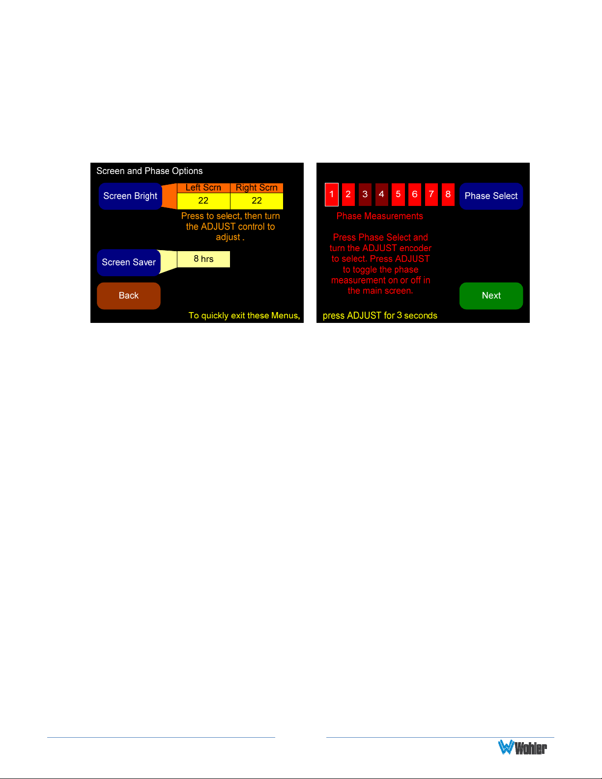
Screen and Phase Options Menu
The Screen and Phase Options menu allows you to adjust the brightness of each
screen independently, and to set the duration of inactivity before the screen saver
activates
Figure 3-5: Screen and Phase Options Menu
1. Screen Bright: Press this control to toggle between the adjustment for the
left screen and the right screen. When a screen is selected, rotate the Adjust
knob to adjust the screen brightness. Thirty-two adjustment steps are
provided for each screen from very dim to bright. The actual brightness of
each screen will change as the control is turned. The default brightness for
both screens is 22.
2. Screen Saver: Pressing this button and then rotating the Adjust knob
selects the screen saver timeout. Select values from 5 minutes to 119
minutes (in 1-minute increments) and from 2 hours to 24 hours (in 1-hour
increments). The default setting is 8 hours.
If the AMP1-8-M is in operation for the screen saver timeout period and no
front panel controls have been turned or pressed, the screens will dim by a
certain amount. If double the screen saver timeout period elapses without
any front panel control activity, the screens will dim further. Operating any
button or control will instantly brighten the screens.
3. Phase Select: Pressing this button and then rotating the Adjust encoder
selects the phase indicator to be adjusted. Press the Select button to turn
the selected phase indicator On or Off. When set to On, an out of phase
condition for the associated pair will be displayed on the Main Screen and
when set to Off, out of phase conditions for the associated pair will not be
displayed on the Main Screen. By default all phase indicators are enabled.
Page20
Page 21
Meter Type and Reference Menu
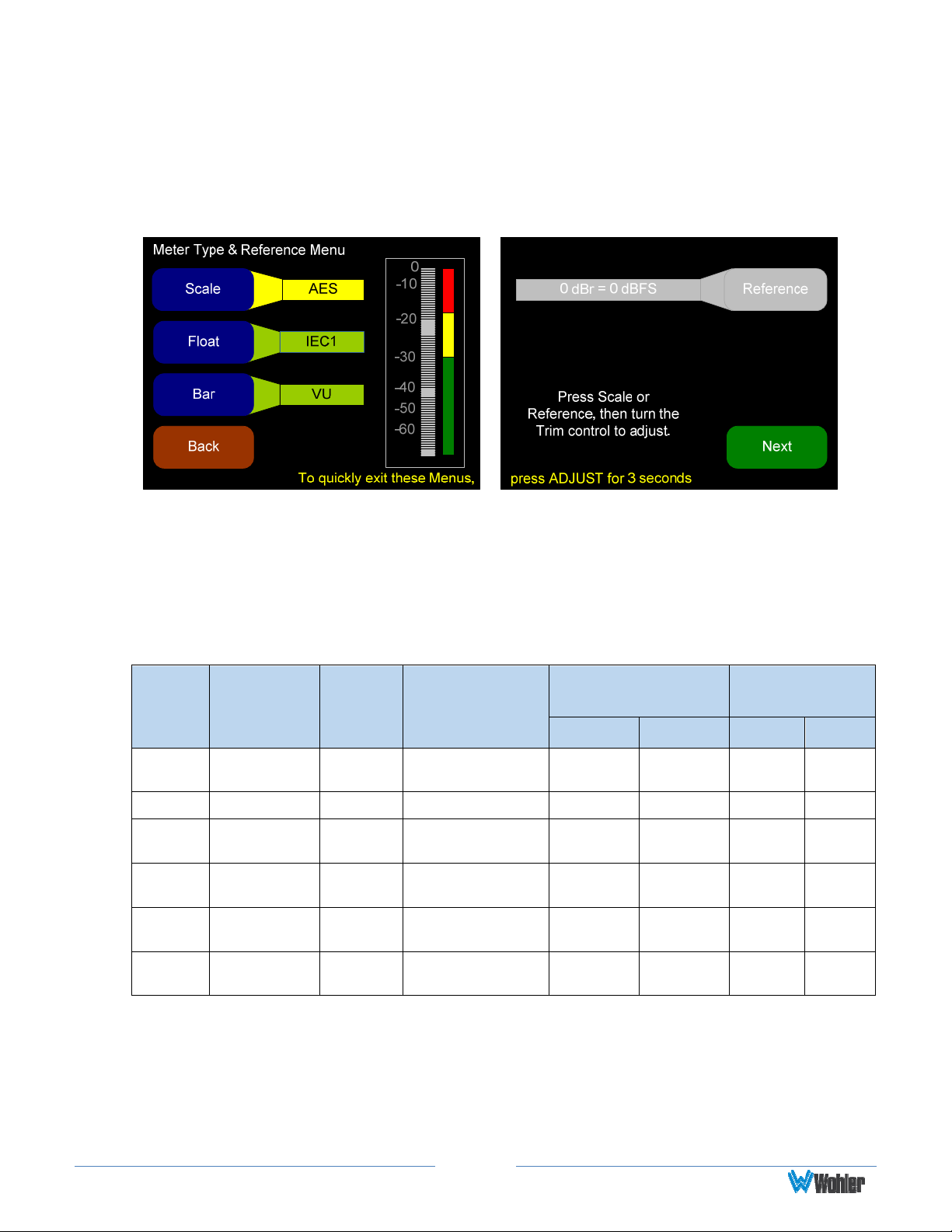
The Meter Type and Reference Menu allows you to define the level meter scale,
float, bar and reference.
Figure 3–6: Meter Type and Reference Menu
1. Scale: Pressing this button and then rotating the Adjust encoder steps
through the scales for the level meters. Six selections are available as shown
in Table 3–1 below.
Table 3–1: Meter Limits and References
Default Color
Scale
Bottom
Limit
Top
Limit
Default
Reference
Bounds
Lower Upper Float Bar
AES -72 dBFS 0.0 dBFS
VU -45 dBr +3.5 dBr
Ext VU -56 Br
BBC
(EBU)
Nordic -44 dBr
DIN -53 dBr +5.5 dBr
-13.25 dBr
+16.0
dBr
+13.0
dBr
+12.5
dBr
0 dBFS = 0 dBFS
-20 dBFS = 0 dBr
-20 dBFS = 0 dBr
-18 dBFS = 0 dBr
-18 dBFS = 0 dBr
-15 dBFS = 0 dBr
-30 dBFS -20 dBFS
-3 dBr 0 dBr - VU
-10 dBr 0 dBr - VU
0 dBr 8 dBr -
-10 dBr 0 dBr -
-5 dBr 0 dBr -
IEC
Type I
Default
Ballistics
VU
IEC
Type II
IEC
Type I
IEC
Type I
2. Float: Pressing this button and then rotating the Adjust encoder adjusts the
ballistics of the floating segment.
Page21
Page 22
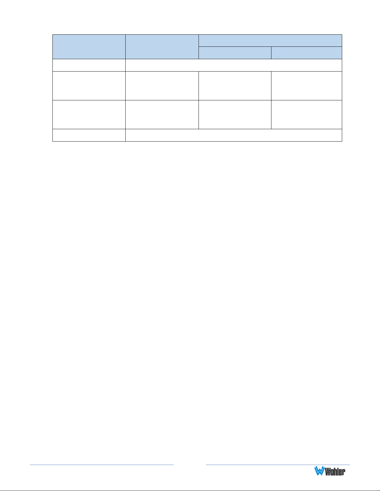
Table 3–2: Meter Timings
Ballistics Rise
Fall
Level Change Time
VU Not Specified
5 ms to reach -2
IEC Type I
dB of settled
-20 dB 1.7 sec.
reading
10 ms to reach -2
IEC Type II
dB of settled
-24 dB 2.8 sec
reading
None Bar or Floating Segment Not Displayed
3. Bar: Pressing this button and then rotating the Adjust encoder steps
through the available settings for the bar ballistics. Refer to Table 3–1 in this
chapter.
4. Reference: Pressing this button and then rotating the Adjust encoder
adjusts the reference. Refer to Table 3–1 in this chapter for the reference
standards for each scale.
Note: The AES scale does not allow you to set a reference.
Page22
Page 23
Meter Segment Menu
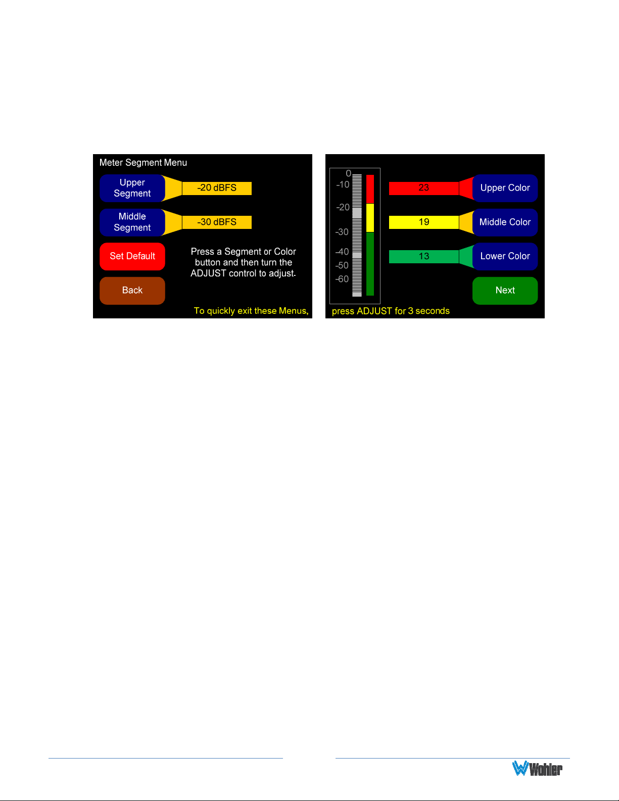
On the Meter Segment Menu, you can customize your level meter segments
thresholds and colors.
Figure 3–7: Meter Segment Menu
1. Upper Segment: Pressing this button and then rotating the Adjust encoder
adjusts the division between the upper and middle segments. You can adjust
the color boundary in 1 dBr increments, and it has the same range as the
bottom and top limits of the meter.
2. Middle Segment: Pressing this button and then rotating the Adjust encoder
adjusts the division between the middle and lower segments. You can adjust
the color boundary in 1 dBr increments, and it has the same range as the
bottom and top limits of the meter.
3. Default: Pressing this button changes the settings on this menu and on the
Meter Type and Reference Menu back to the factory settings for the
chosen scale type.
4. Upper, Middle, and Lower Color: Pressing this button and then rotating
the Adjust encoder knob cycles the upper, middle, or lower color of the
displayed sample level meter color through a wide variety of colors.
Page23
Page 24
Version and Ethernet Menu
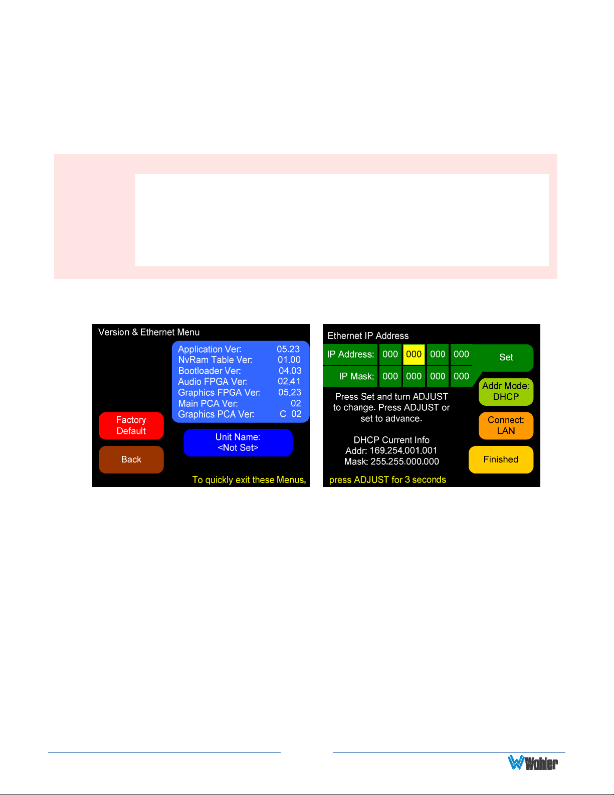
This menu displays software and hardware versions, as well as Ethernet settings.
By default, the DHCP setting is enabled and the IP Address and IP Mask settings are
shown as 000.000.000.000. This means it will automatically attempt to get the
needed IP Address and IP Mask settings from the network.
Note:
The AMP1-8-M does not currently use the Ethernet port except during
factory programming. For normal operation, the port may be connected
to a LAN or disconnected.
In future releases, Wohler may or may not release remote control
software for this unit, such as is used in the AMP1-16-M.
Figure 3–8: Versions and Ethernet Menu
1. Factory Default: Pressing this button opens a cautionary window to verify that
you really want to restore the AMP1-8-M setup to the factory default. If you p ress
the Factory Default button again, the action proceeds and the unit will restart.
Otherwise, after five seconds, the factory default request is cancelled. You can also
cancel the factory default request by pressing any other button.
i. Note: The Factory Default action restores the entire unit to its
factory condition. The unit name is deleted, the IP Address is set to
DHCP, and the Connect: setting s reset to LAN.
2. Set (IP Address or IP Mask): Pressing this button highlights the first of the four
octets. Turning the Adjust encoder clockwise increases the octet while turning it
counterclockwise reduces the octet. Pressing either the Set IP Address or the
Adjust encoder advances the highlight to the next octet. Advancing beyond the last
octet returns the highlight to the first octet.
Page24
Page 25

”
Important:
If the IP information has been changed, the unit will have to restart. A
warning diamond will display, and you will need to confirm or cancel
before proceeding.
If the information in the IP fields is not correct, the changes made in the
IP fields will be ignored. The IP address is valid if the screen reads “DHCP
Mode Enabled” or “Static IP Mode Enabled.
3. Addr Mode: Pressing this button selects between DHCP and Static address
modes. Note: Switching to a static IP will automatically cancel the direct
connection selection.
4. Connect: Pressing this button selects between a LAN connection and a Direct
connection. Note: Choosing the direct connection will automatically put the unit
into DHCP mode.
Important:
This enables a single-address DHCP server. Thus, when a computer is
connected directly, both the unit and the host computer will be assigned a
DHCP address, and they will be able to communicate. However, this
setting will cause problems with some LANs. If this unit will be connected
to a LAN, leave this setting in the Connect: LAN setting which disables the
internal DHCP server.
5. Finished: Pressing this button closes this menu and returns to the Monitoring
Screen.
Page25
Page 26

CHAPTER 4 - Features and
Specifications
Introduction
This chapter lists the features and specifications of the AMP1-8-M.
Features
1. Totally digital system architecture with high fidelity Class D amplifiers
2. Volume and Balance controls can optionally become Left Volume and
Right Volume controls
3. Quick push-button selection of SDI channels to sum to monitor
4. Dual 3G/HD/SD-SDI inputs for audio monitoring
5. Regenerated loop outputs of each SDI input
6. Re-clocked output of the selected SDI input
7. Balanced stereo analog outputs on XLR-M: optionally Volume/ Balance
controlled or fixed line output
8. Front panel ¼” headphone jack
9. Automatic frame rate detection and selection
10. Level metering for 8 (of 16) de-embedded SDI channels
11. High resolution metering with 166 segments displayed
12. Level Meter Representation: Simultaneous average and PPM
13. Brightness control for each screen, 32 levels
14. Permanent internal storage for all options and settings
15. Easy update management software
16. Shallow chassis depth
17. IEC power input, 100 – 240 VAC +/- 10%, 50/60 Hz
18. Phase indicators for each stereo input channel pair
19. User selectable meter scale, color thresholds, and ballistics
Page26
Page 27
Compliance
All components comply with UL, CE, and RoHS specifications.
The AMP1-8-M meets FCC Part 15 compliance.
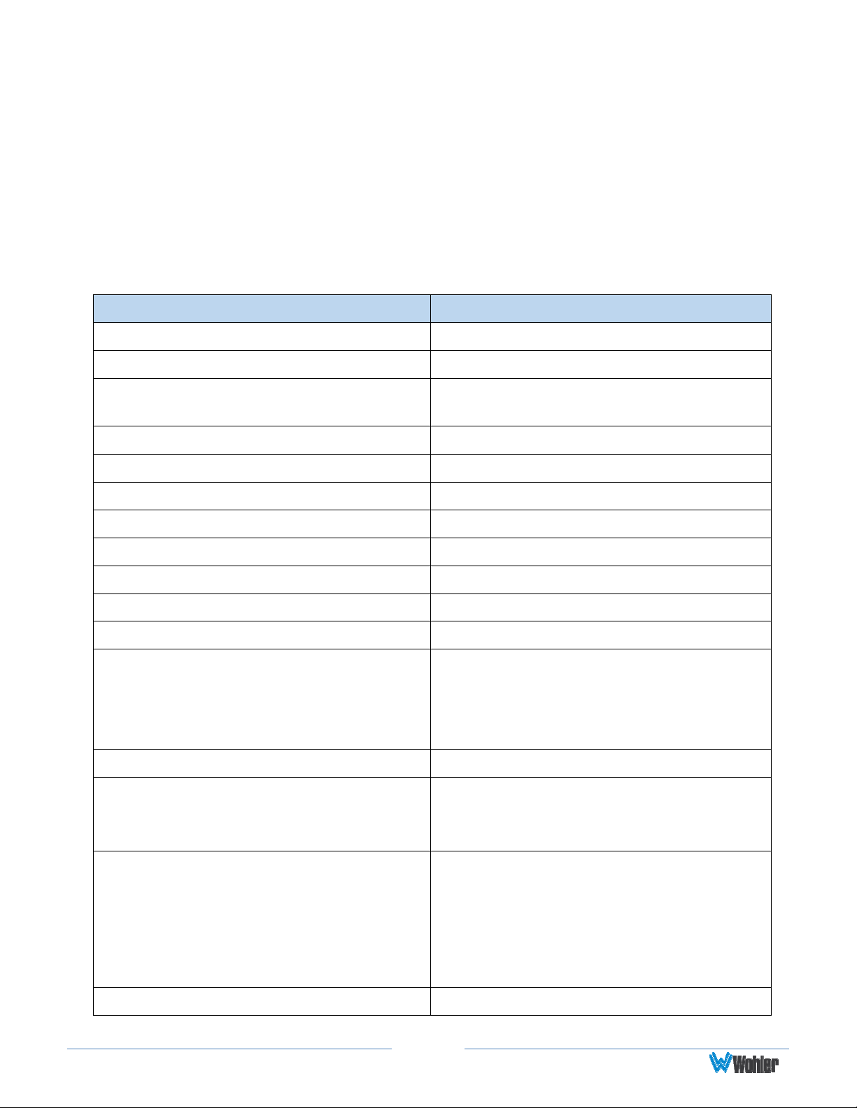
Specifications
Table 4-1: Specifications
Specification Values / Domains
Power requirements
Power consumption 60 Watts
Dimensions (H x W x D)
Weight
Space Required 1 RU (rack unit)
Supplied Accessories AC Power Cord (North America)
Display Type TFT LCD
Number of Displays 2
Screen Size 2.4” diagonal per screen
Screen Resolution 320 x 240
Inputs SDI: 2 3G/HD/SD-SDI on BNC
Outputs
100 V to 240 V AC ± 10%, 50/60Hz
1.75” x 19” x 4.25”
(44mm x 483mm x 107mm)
5 lbs. (2.3 kg)
SDI: 2 regenerated on BNC
SDI: 1 selected reclocked on BNC
Analog: 2 balanced channels on XLR-
M
Level Meters 166 segments
Selectable:
Level Meter Scales
Level Meter Characteristics
Peak Acoustic Output
Page27
AES; VU; Ex. VU; BBC; EBU;
Nordic; DIN
Selectable:
Meter thresholds
Reference
Segment Colors
Ballistics
90dB SPL (@ 2 feet)
Page 28
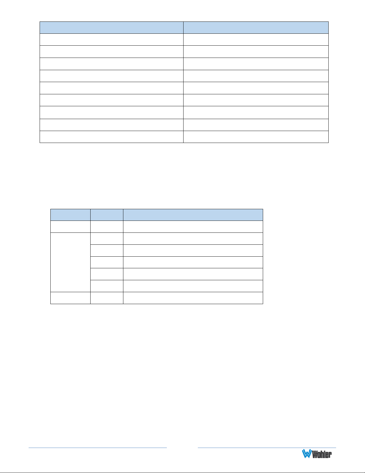
Specification Values / Domains
Power Output RMS
Frequency Response
Analog Output Reference Level
Analog Output Frequency Level
Analog Output Distortion
Analog Output Dynamic Range
SDI Input Termination
Hum and Noise
Electrical Distortion
Audio Formats
All of the audio formats listed in Table 4–2 below are available for monitoring in the
AMP1-8-M.
6 W RMS, 12 W peak (each side)
150 Hz to 16 kHz (± 5 dB)
-20 dBFS = +4 ± 1.0 dBu
40 Hz to 20 kHz (± 1dB)
<0.01% THD+N
> 100 dB
75 unbalanced
Better than -68 dB below full output
<0.05% at any level below limit threshold
Table 4-2: Audio Formats
Standard Format Rate
SD 29.97; 25
720p 23.98; 24; 25; 29.97; 30; 50; 59.94;60
1035i 29.97; 30
HD
3G 1080p 50; 59.94; 60
1080i 25; 29.97; 30
1080sf 23.98; 24; 25; 29.97; 30
1080p 23.98; 24; 25; 29.97
Page28
Page 29
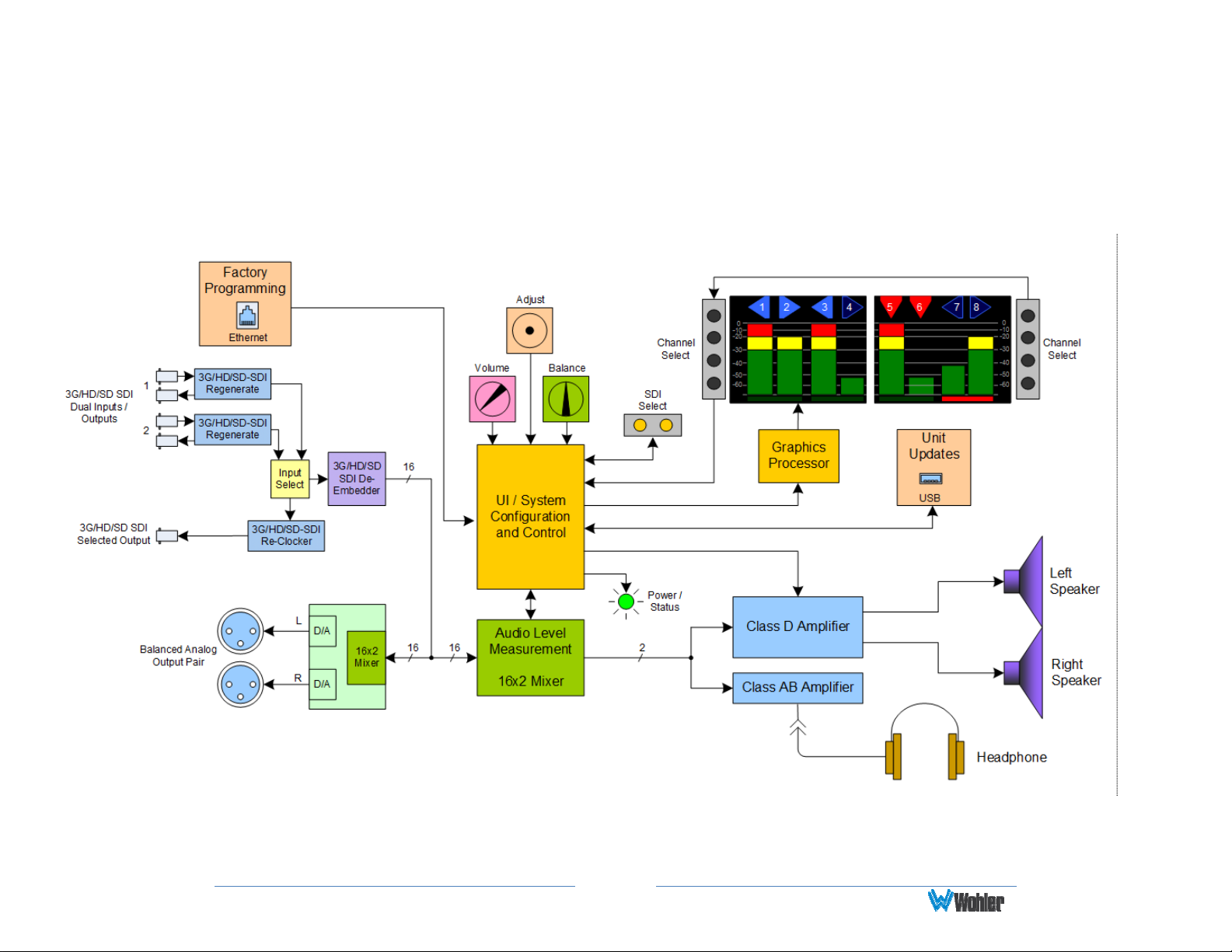
Technical Functional Overview
Figure 4-1 illustrates the overall functionality of the AMP1-8-M monitor.
Figure 4–1: AMP1-8-M Block Diagram
Note: Stereo phase indication measurement occurs in the signal chain before it is routed to the speakers.
Page29
Page 30
APPENDIX A: Upgrading the AMP1-8-M
Using a USB Flash Drive
Introduction
This chapter describes how to download software upgrades to your PC using a USB
Flash Drive.
Important:
When a new version becomes available, software updates may be
obtained in .zip file format from the Wohler Website. Download this zip
file, unzip it, and place the "AMP1-8-MProgrammingFiles" f older on a
standard USB flash drive. Insert the flash drive into the unit, and follow
the instructions below.
Upgrading the Software Using a USB Flash Drive
1. Insert the USB flash drive into the unit.
2. If the USB flash drive has firmware files on it, the green Update Menu
button will appear on the right screen. If the firmware files are missing, this
button will not appear. See Figure A-1 below.
Figure A–1: Flash Drive Connected Screen
3. Press Update Menu.
Page30
Page 31
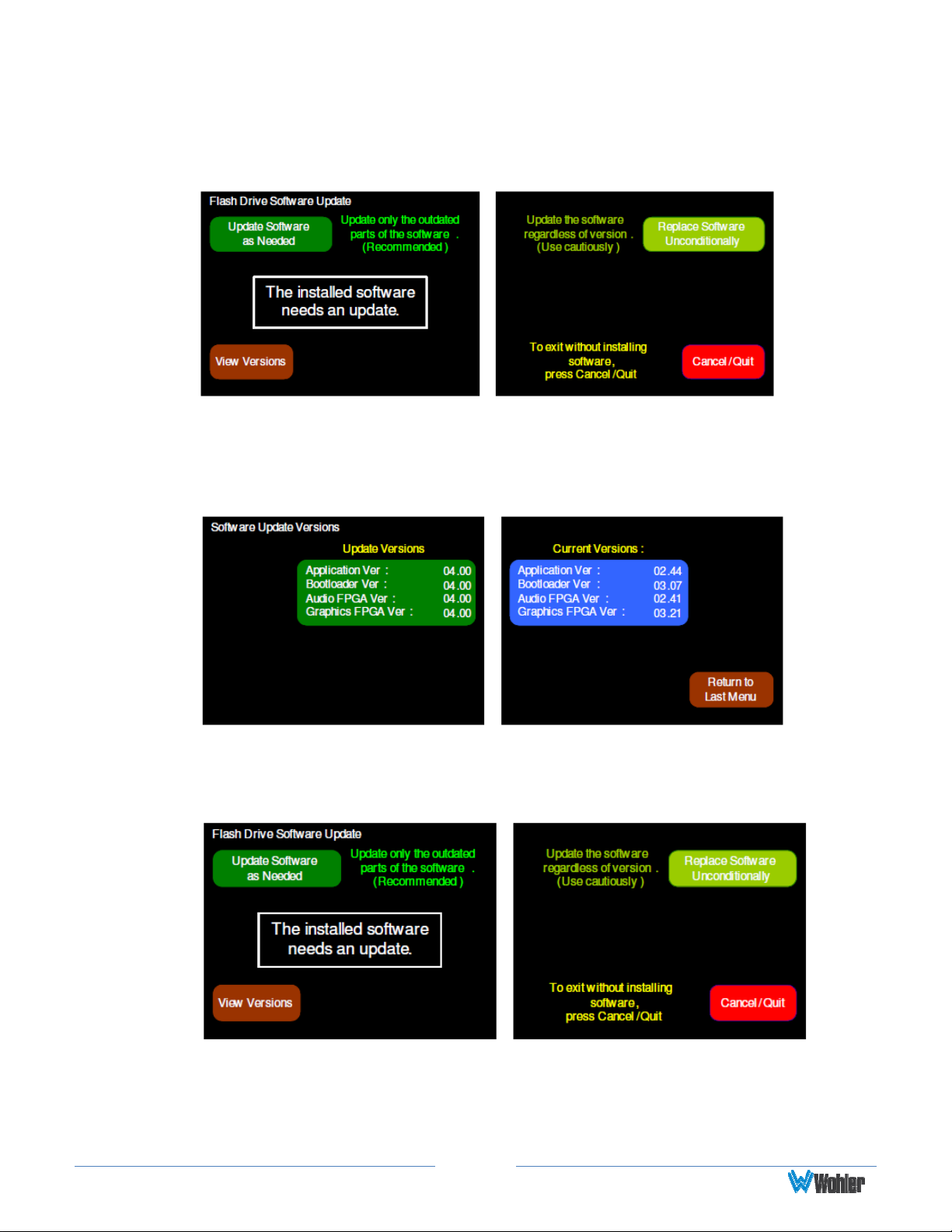
4. All the firmware files on the USB drive will be read and validated. This will
take a few minutes, and progress screens are presented. Once the validation
is finished the following menu appears:
Figure A–2: Flash Drive Software Update Screen
5. If you wish, you may use the View Versions button to display the current
versions in the unit against those on the flash drive, as shown in the next
figure.
Figure A–3: Software Update Versions Screen
6. From the Software Update Versions menu, press Return to Last Menu to
return to the Flash Drive Software menu shown in Figure A-4 below.
Figure A–4: Software Software Update Screen
If the screen does not indicate that the software is up to date, you can select
one of two update options:
a. Press the Update Software as Needed button to install only newer
Page31
Page 32
software versions contained in the flash drive into the AMP1-8-M. The
next screen to appear will describe what to expect in the installation
process
b. Alternatively, you can press the Replace Software Unconditionally
button to install the software contained in the flash drive into the
AMP1-8-M, even if it the same version already is installed and even if
the flash drive version is a lower version than what is already installed.
The next screen to appear will describe what to expect in the
installation process.
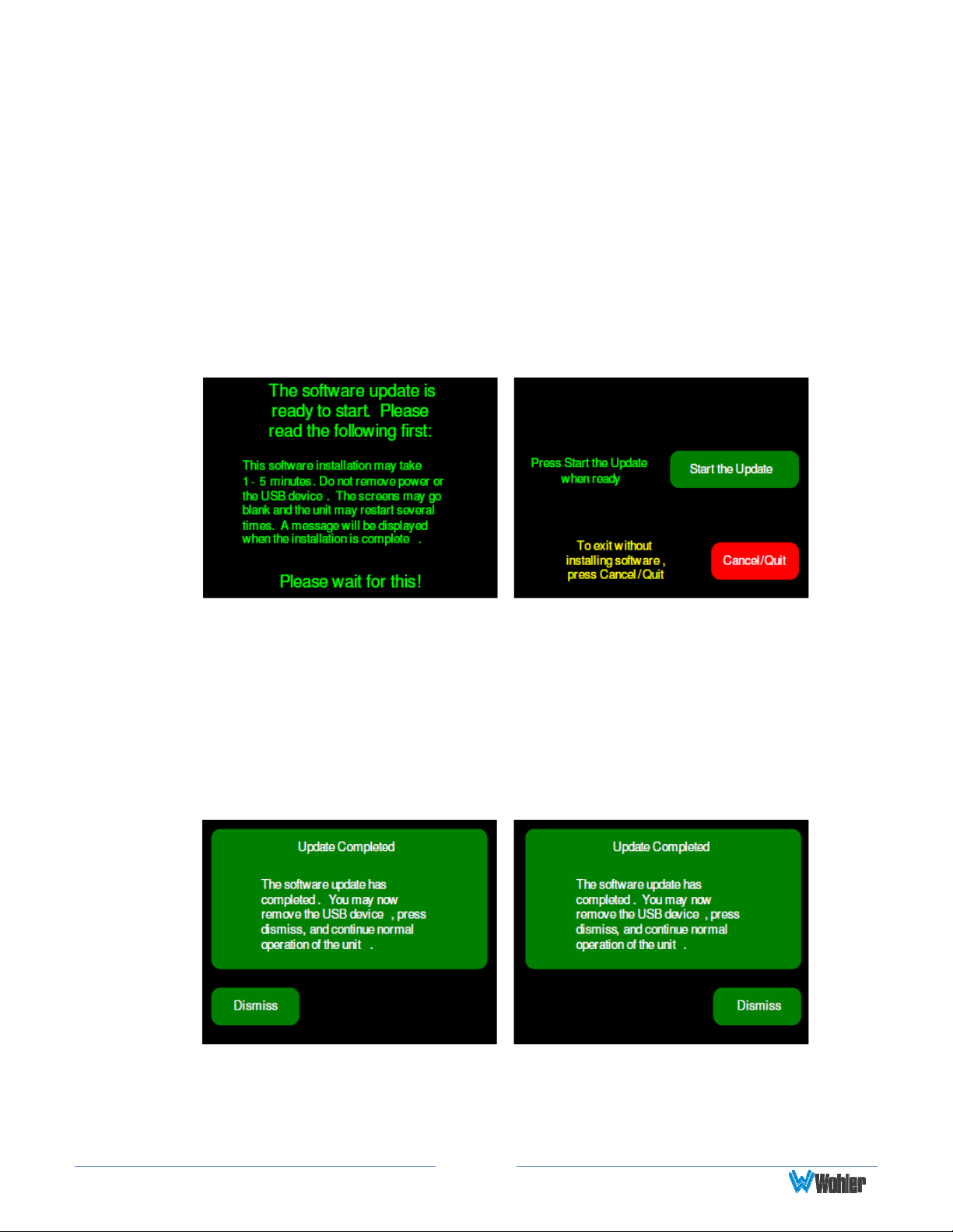
7. After you have selected a software installation option, the system will display
the Software Update screen shown in Figure A-5 below.
Figure A–5: Flash Drive Software Update Screen
8. Pressing Start the Update button will start the installation process, which
will automatically continue until its conclusion. Instructions are provided on
this screen to explain the process.
Alternatively, you may press the Cancel/Quit button to return to the Flash
Drive Software Update menu and not perform the software update.
9. When the software is finished installing, the AMP1-8-M will restart and the
Main Screen will display the message in Figure A-6 below.
Figure A-6: Flash Drive Software Update Complete Screen
This concludes the USB firmware update procedure.
Page32
 Loading...