

WLINK WL-G510 User Manual

WL-G510 Series Router User Manual
1
V1.0
http://www.wlink-tech.com
March, 2018
User Manual
---Apply to WL-G510 Series Industrial 4G/3G Router
V1.0
http://www.wlink-tech.com
March, 2018

WL-G510 Series Router User Manual
2
Copyright © Shenzhen WLINK Technology Company Limited 2012 ~ 2018
Without our written approval, anyone can’t extract, copy whole or part of content of this file and can’t spread
out in any format.
Caution
Due to product updates or functional upgrading, we may renew the content of this file, and this file only for
reference. All statement, information, suggestion .etc in this file does not compose any form of guarantee and
we WLINK reserves the right of final explanation.
Shenzhen WLINK Technology Company Limited
Add:
3F, Yiben Building, Chaguang Road, Xili, Nanshan Dist., China, 518000
Web:
http://www.wlink-tech.com
Service Email:
support@wlink-tech.com
Tel:
86-755-86089513
Fax:
86-755-26059261

WL-G510 Series Router User Manual
3
Contents
1 Hardware Installation
..............................................................................................................................................
4
1.1 Panel
..............................................................................................................................................................
4
1.2 LED Status
....................................................................................................................................................
6
1.3 Dimension
.....................................................................................................................................................
7
1.4 How to Install
................................................................................................................................................
7
2 Router Configuration
............................................................................................................................................
10
2.1 Local Configure
..........................................................................................................................................
10
2.2 Status
...........................................................................................................................................................
11
3.3 WLAN Setting
.............................................................................................................................................
18
3.4 Advanced Network Setting
......................................................................................................................
21
3.5 Firewall
........................................................................................................................................................
29
3.6 VPN Tunnel
................................................................................................................................................
31
3.7 Administration
............................................................................................................................................
40
3.8 Debugging Setting
.....................................................................................................................................
52
3.9 “Reset” Button for Restore Factory Setting
...........................................................................................
55
3.10 Appendix (For advanced optional features only)
...............................................................................
56
WL-G510 Series Router User Manual
4
1 Hardware Installation
This chapter is mainly for installation introduction, there would be some difference between the scheme
and real object. But the difference won’t have any influence to products performance.
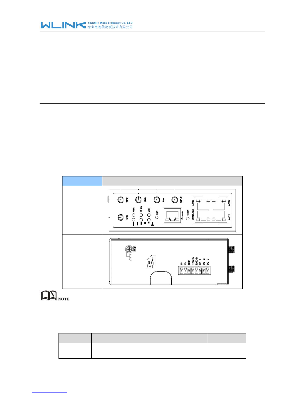
1.1 Panel
Table 1-1 WL-G510 Structure
WLINK Tech.
G510 series
Front
Top
There are some difference on Antenna interface and indicator light for the device with extended
Wi-Fi, GPS features.
Table 1-2 Router Interface
Port
Instruction
Remark
USIM
Plug type SIM Slot, support 1.8/3V/5V automatic
detection.
WL-G510 Series Router User Manual
5
Port
Instruction
Remark
Main
LTE antenna, SMA connector, 50Ω.
Aux
LTE MIMO antenna
GPS
GPS antenna, SMA connector, 50Ω.
Wi-Fi1
Wi-Fi dual-band antenna, SMA connector
Wi-Fi2
Wi-Fi dual-band antenna, SMA connector
LAN
10/100/1000Base-TX,MDI/MDIX self-adaption.
WAN/LAN
10/100/1000Base-TX,MDI/MDIX self-adaption.
Default as LAN
Reset
Reset button, (press on button at least 5 seconds)
PWR
Power connector
7.5~32VDC
I/O
DI-1 and DI-2 are digital input, and DO is digital
output.
Console
RJ45-DB9 cable for CLI configuration.
WL-G510 Series Router User Manual
6
1.2 LED Status
Table 1-3 Router LED indictor Status
silk-screen
status
Indication
Signal
Signal
Solid Light
LED1: weak (CSQ0~10).
LED2: good (CSQ11~19)
LED3: strong (CSQ20~31)
Signal 1
Blink
dialing
Solid Light
online
PWR
Solid Light
System power operation.
WLAN
Solid light
WLAN enable, but no data communication.
Blinking quickly
Data in transmitting
Dark
WLAN disable
ERR
Dark
System operation and LTE/3G online.
Solid Light(Red)
System fail indicator. It indicates SIM card/ module
fail.
LAN
Green
Solid light
Connected
Green
Blinking
Data in transmitting.
Green
Dark
Disconnection.
There are some difference in the LED indicator of the router with expanded Wi-Fi, GPS function
and single module dual SIM.
WL-G510 Series Router User Manual
7
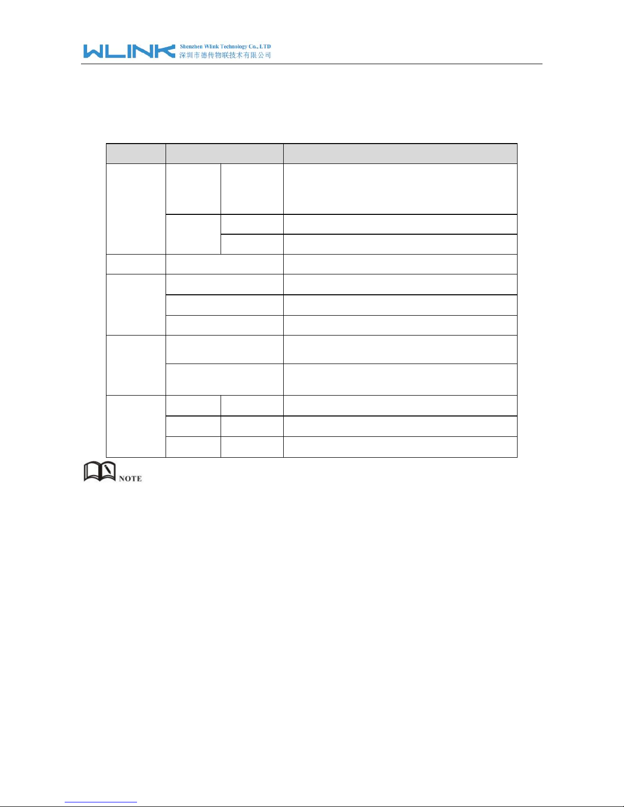
1.3 Dimension
Figure 1-2 G510 Series Router Dimension
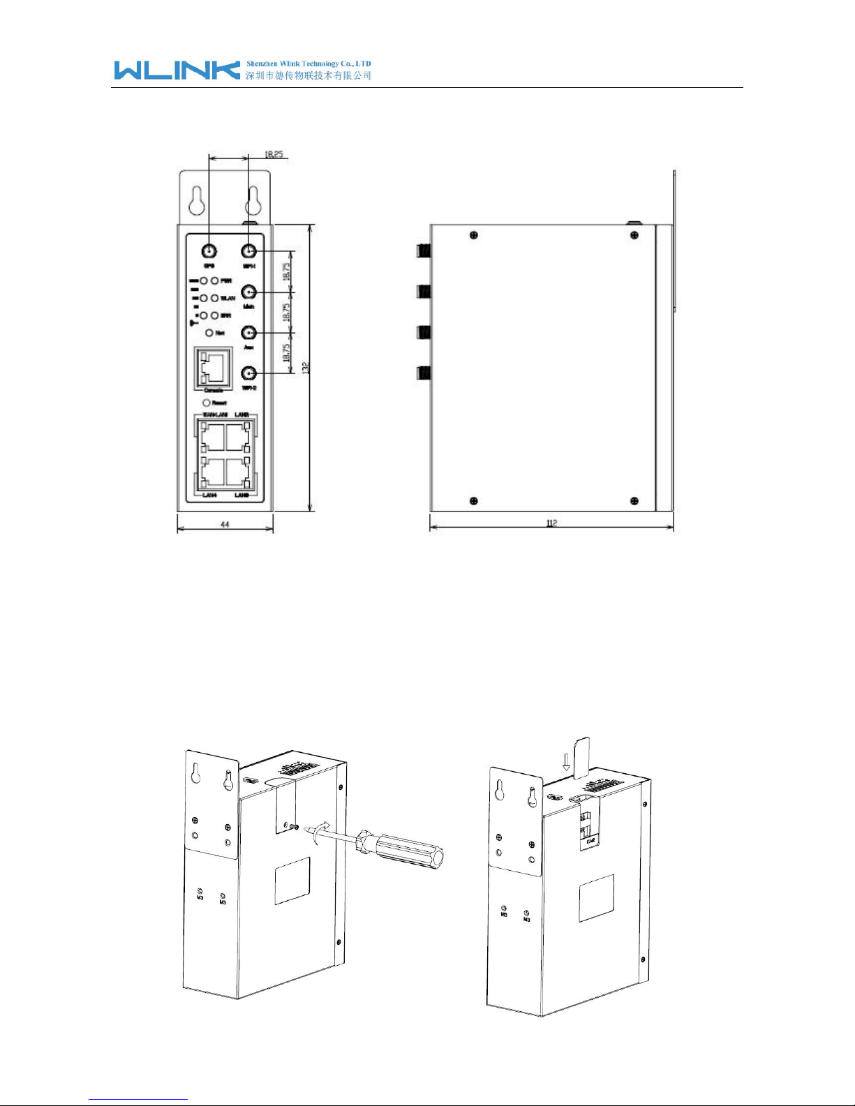
1.4 How to Install
1.4.1
SIM/UIM card install
Please insert the dual SIM cards before configure the router.
WL-G510 Series Router User Manual
8
Before connecting, please disconnect any power resource of router
1.4.2 Ethernet Cable Connection
Connect the router with a computer by an Ethernet cable for GUI configuration, or transit by a switch.
1.4.3 4G and Wi-Fi
Antenna Plug
Connect the two magnetic 4G antennas to Main and Aux interfaces, and the two paddle shape Wi-Fi
antennas to Wi-Fi1 and Wi-Fi2 interfaces.
Wi-Fi antenna supports dual-band 2.4G and 5G band.
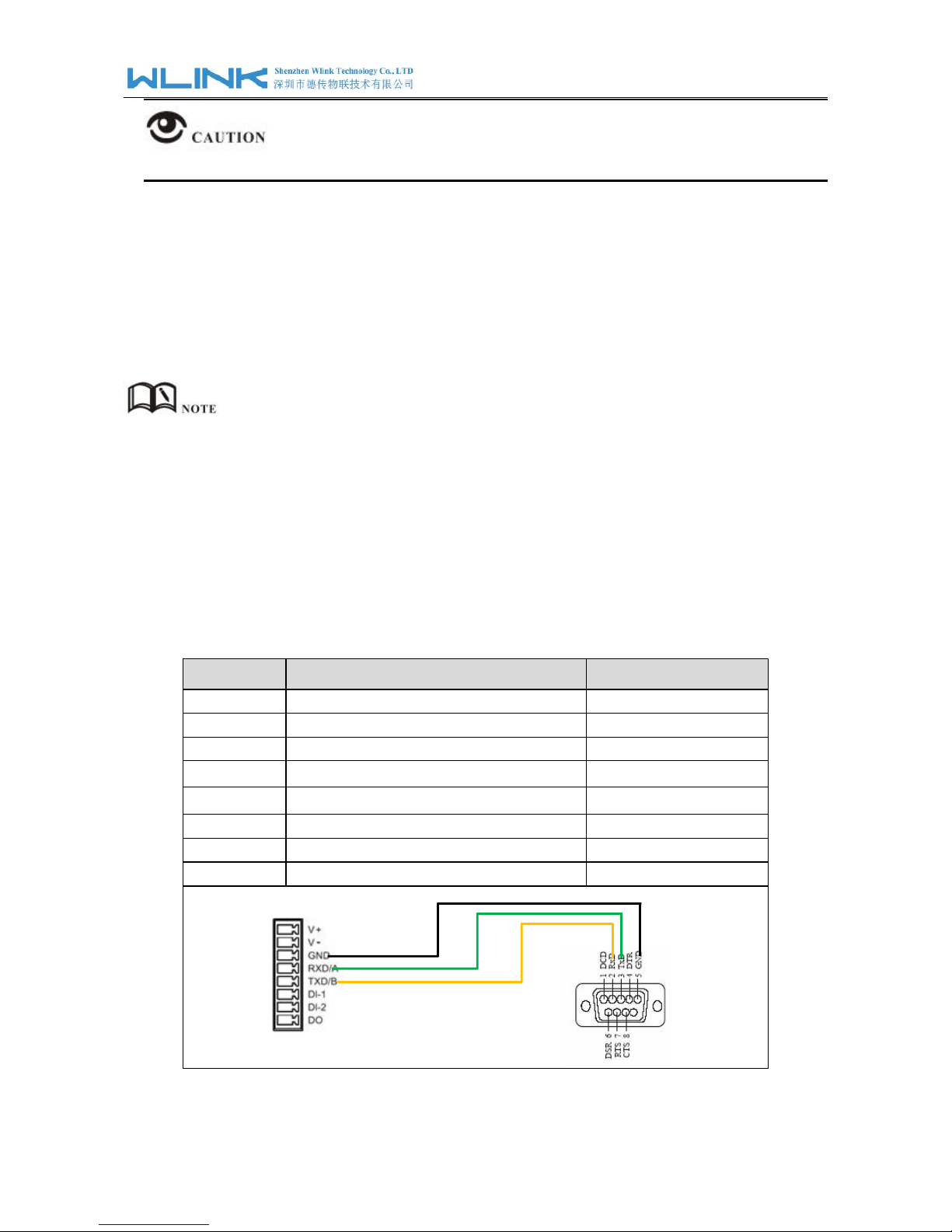
1.4.4 Serial Port (Terminal block) Connection
The serial port supports alternative RS232/RS485 port, and RS232 port as default. It might be requested
serial port for RS485 when place order. The serial port feature supports TCP/UDP client/server as
optional, also supports Modbus protocol. You may check the feature in Serial App of Advanced Network
UI. Below is RS232 connection sequence as reference.
Pin
Instruction
Remark
1
V+
Power V+, Anti reverse
2
V-
Power V-
3
GND
GND for RS232 communication
4
RXD/A
RS232 RXD, 57600bps as default
5
TXD/B
RS232 TXD, RS485 optional
6
DI-1
Digital Input, Dry Contact
7
DI-2
Digital Input, Dry Contact
8
DO
Short to GND
WL-G510 Series Router User Manual
9
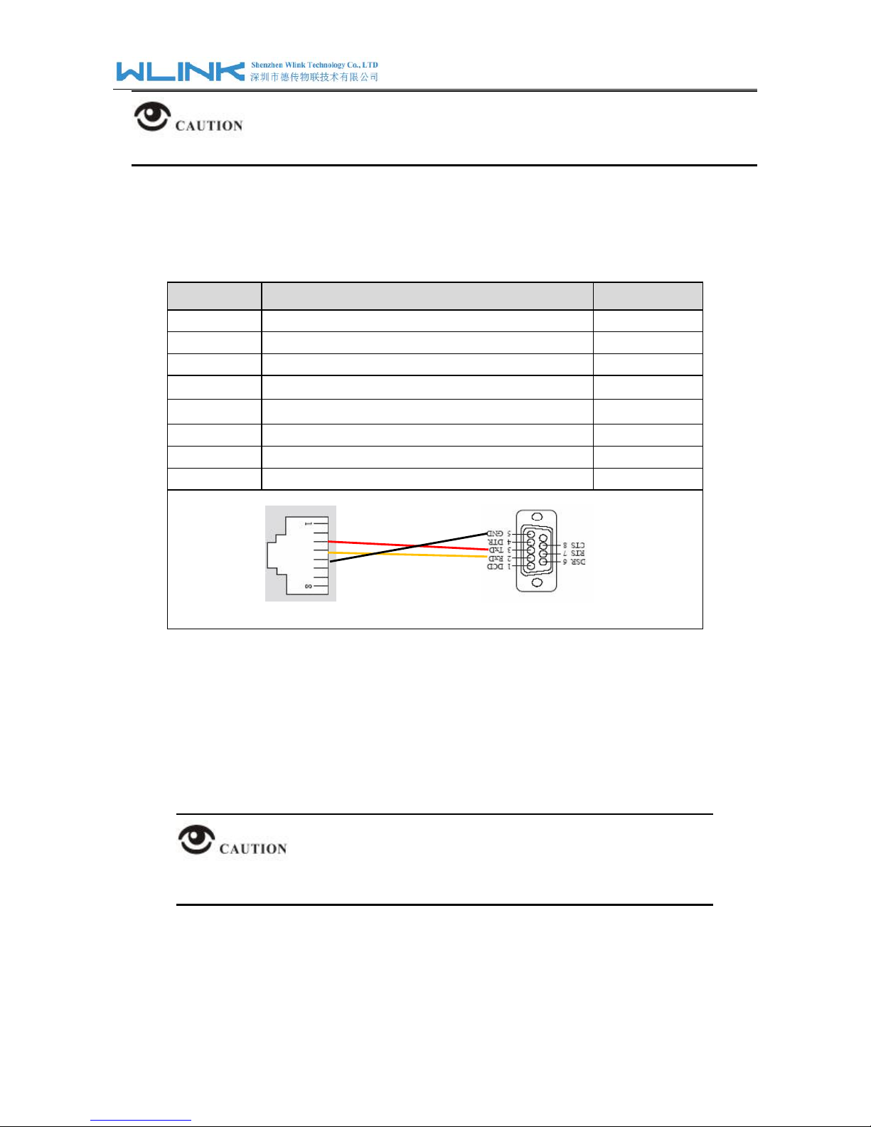
The serial port will be unavailable in WL-G510 standalone GPS model.
1.4.5 Console
Port Connection
Connect the router to a computer by an RJ45-DB9 cable for CLI configuration and router
system debugging.
Pin
Instruction
Remark
1
CTS
Input
2
RTS
Output
3
RXD
Input
4
TXD
Output
5
GND
GND
6
DSR
Input
7
DCD
Output
8
DTR
Output
1.4.6 Power Supply
Plug in power adaptor.Voltage input range:+7.5~32VDC. (Extended models: 7.5~ 48VDC)
1.4.7 Review
After insert the SIM/UIM card and connect Ethernet cable and antenna, connect power
supply adaptor or power cable.
Please connect the antenna before power on, otherwise the signal maybe poor
because of impedance mismatching.
Notice:
Step 1 Check the antenna connection.
Step 2 Check SIM/UIM card, confirm SIM/UIM card is available.
Step 3 Power on the industrial Router
----END

WL-G510 Series Router User Manual
10
2 Router Configuration
WL-G510 Series routers support GUI and CLI configuration. This chapter introduce GUI
configuration via Ethernet port, if need CLI configuration guide, please contact our
technical support department by email: support@wlink-tech.com.
2.1 Local Configure
The router supports to be configured by local Ethernet port, you could specify a static IP or
set as DHCP. The default IP address is 192.168.1.1 , subnet mask is 255.255.255.0,
please refer to followings:
Step 1 Click
“start > control panel”,find “Network Connections” icon and double click it to
enter, select “Local Area Connection” corresponding to the network card on this
page. Refer to the figure below.
Figure 2-3
Network Connection
Step 2
Obtain a IP address automatically or set up IP address,192.168.1.xxx(XXX can be
any number between 2~254)
Step 3
Run an Internet Explorer and visit “
http://192.168.1.1/
”, to enter identify page.
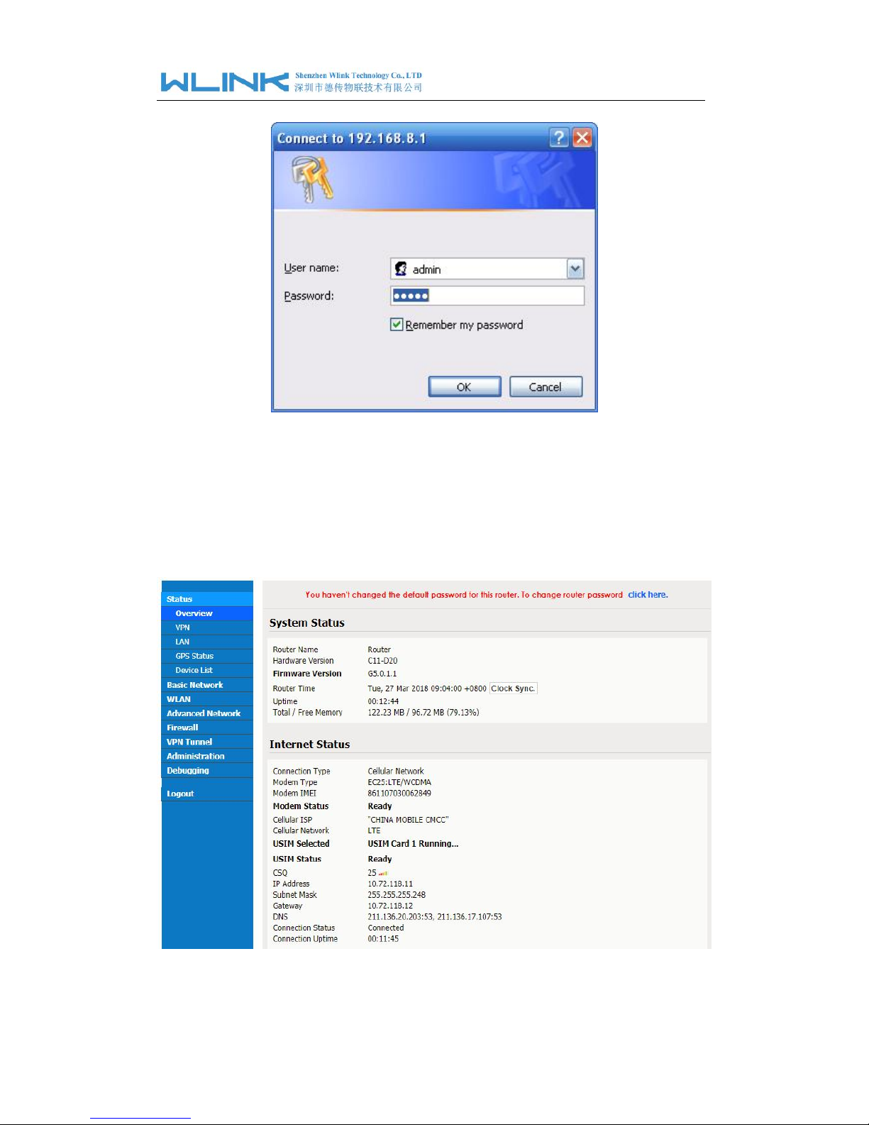
WL-G510 Series Router User Manual
11
User should use the default user name and password when log in for the first time
Figure 2-4 User Identify Interface
----END
2.2
Status
Check routers status after login router.
Figure 2-5 Router Status GUI
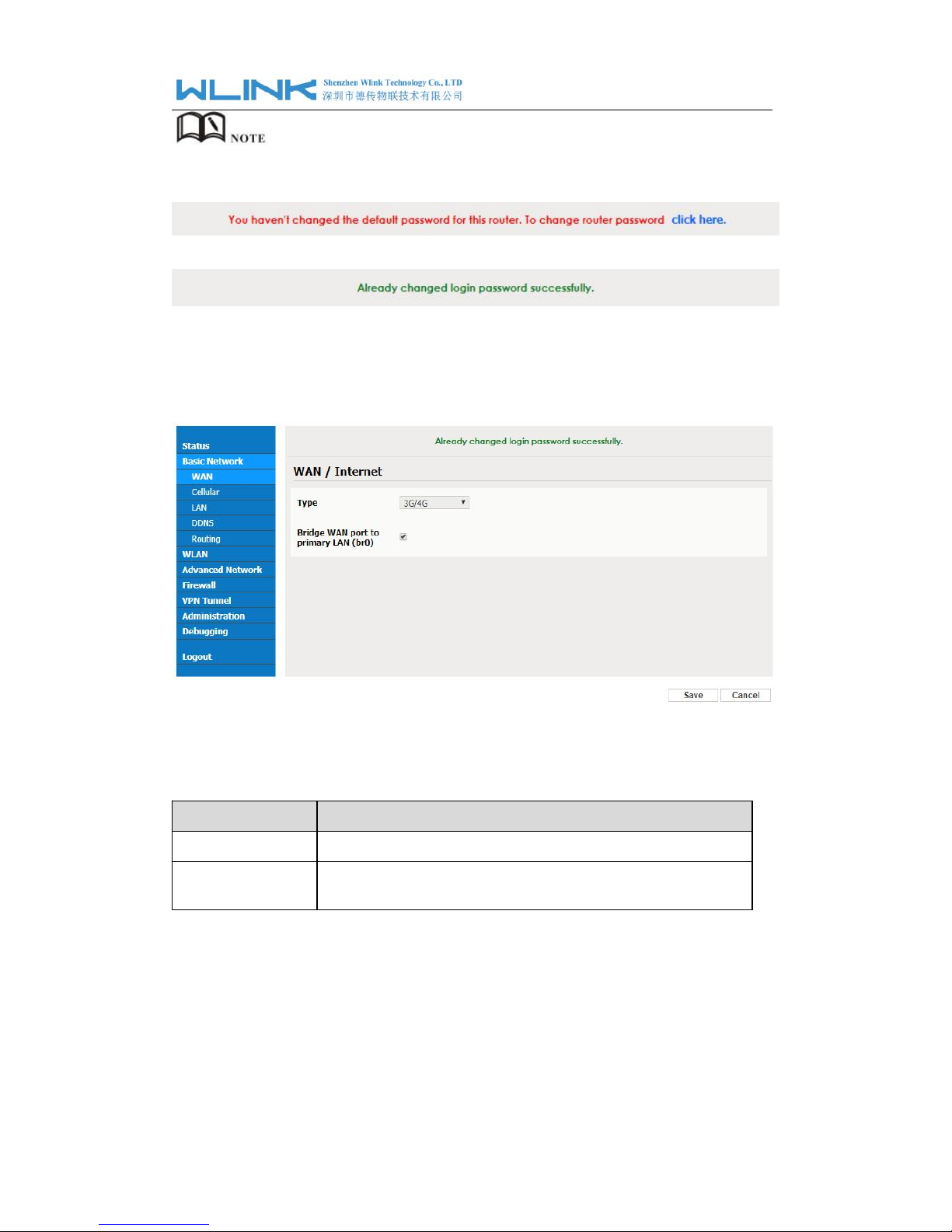
WL-G510 Series Router User Manual
12
After login, router status will be show as below, then you should change the password
according to the prompts.
The UI will display” already changed login password successfully” after router reboot.
3.2.1 WAN Setting
Step 1 Basic Network>WAN to enter below interface
Figure 3-1
WAN Setting GUI
Table 3-1 WAN Setting Instruction
Parameter
Instruction
Type
Support 3G/4G, PPPoE, DHCP, Static IP
Bridge WAN to
LAN
Configure WAN port as LAN port
Step 2 After setting, please click “save” to finish, the device will reboot.
----End
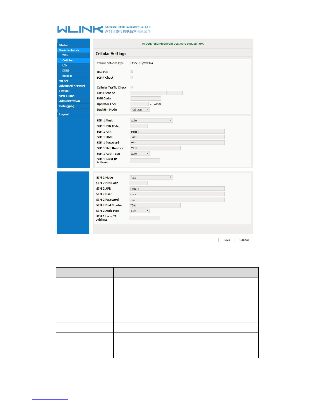
3.2.2 Cellular Network Configure
Step 1 Basic Network-> Cellular, you can modify relevant parameter according to the
application.
WL-G510 Series Router User Manual
13
Figure 3-2 Cellular Setting GUI
Parameter
Instruction
Use PPP
ECM dialup as default. PPP optional.
ICMP check
If enable ICMP check and setup a reachable IP address as
destination IP, the router will reconnect/reboot once ICMP
check failed.
Cellular Traffic Check
The router will reconnect/reboot once there’s no Rx/Tx data.
CIMI Send to
Send CIMI to a defined IP and port by TCP protocol.
SMS Code
Remote control the router by SMS. Only the configured SMS
code will work.
Operator Lock
Lock a specified operator for the router by MCC/MNC code.
WL-G510 Series Router User Manual
14
Parameter
Instruction
Dual SIM Mode
【Fail Over】Two SIM cards mutual backup. Once SIM1 failed,
it’ll switch to SIM2 and work on SIM2, and vice versa.
【
SIM1 Only】Only SIM1 works.
【
SIM2 Only】Only SIM2 works.
【
Backup】SIM1 is the primary SIM. Once SIM1 failed, it’ll switch
to SIM2 and work on SIM2 for a specified period of time, then it
switches back to SIM1.
Connect Mode
【Auto】The router will automatically connect to 3G/4G networks
and give priority to 4G.
【LTE】Router will connect to 4G only.
【3G】Router will connect to 3G only.
Pin Code
Some SIM cards are locked with a Personal Identification Number
(PIN) code in case they are lost or stolen.
APN
APN is provided by local ISP, usually CDMA/EVDO networks
do not need this parameter.
User
SIM card user name is provided by ISP
Password
SIM card password is provided by ISP
Auth. Type
Auto/PAP/Chap/MS-Chap/MS-Chapv2 authentication optional.
SIM Local IP Address
Fix SIM IP. The feature is available if carrier can provide this service.
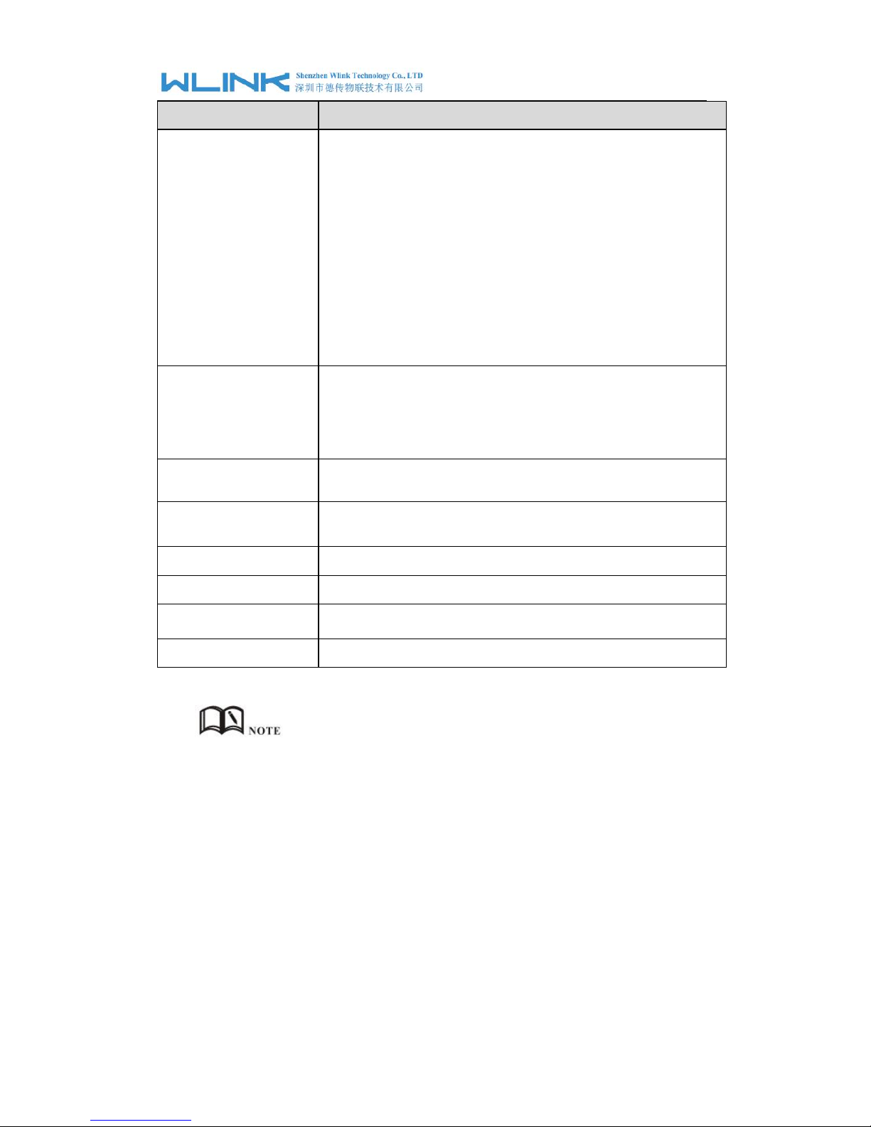
ICMC Check and Cellular Traffic Check are alternative.
【ICMP Check】
Enable ICMP, Router will automatically check whether the defined IP address is
reachable per 60s. If the IP address is unreachable and ICMP check is timeout at
the first time, it will check 2 times every 3 seconds. If the third time is still failed, the
router will redial.
The ICMP Check IP is a public IP or company server IP address.
WL-G510 Series Router User Manual
15
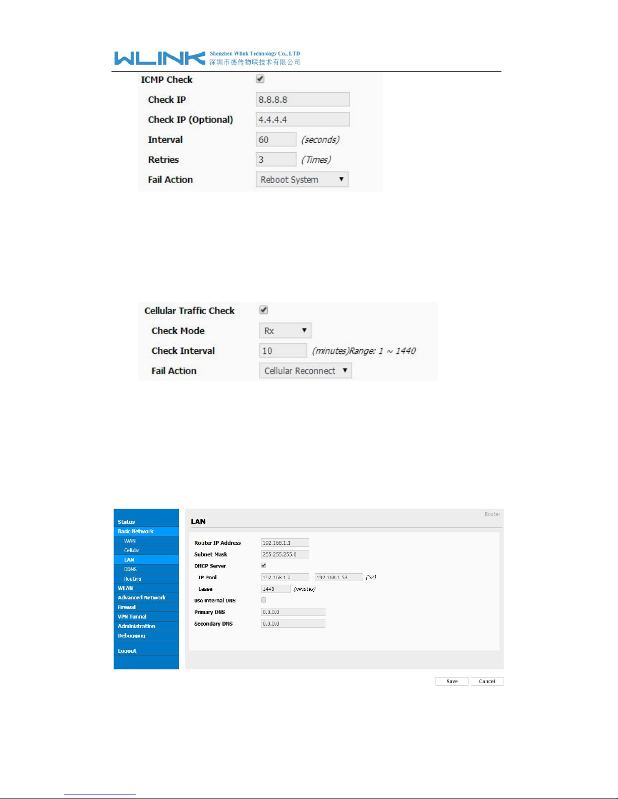
【
Cellular Traffic Check
】
【
Check Mode】there are Rx(Receive), Tx(Transmission) and Rx/Tx check modes.
【Rx】Router will check the 3G/LTE cellular receiver traffic. If no receiver traffic within
the defined check interval, the router will implement the specified action reconnect
or reboot.
Step 2 After Setting, please click “save” icon.
----End
3.2.3 LAN Setting
Step 1 Basic Network>LAN to enter below interface
WL-G510 Series Router User Manual
16
Figure 3-3
LAN Setting GUI
Table 3-2 LAN Setting Instruction
Parameter
Instruction
Router IP Address
Router IP address, default IP is 192.168.1.1
Subnet Mask
Router subnet mask, default mask is 255.255.255.0
DHCP
Dynamic allocation IP service, after enable, it will show the
IP address range and options of lease
IP Address Range
IP address range within LAN
Lease
The valid time
Use Internal DNS
If click this option, router will use 3G/4G network DNS which is
assigned by 3G/4G network. If not click this option, router will
use custom DNS
Primary DNS
Available as customer configured
Secondary DNS
Available as customer configured
Step 2 After setting, please click “save” to finish, the device will reboot.
----End
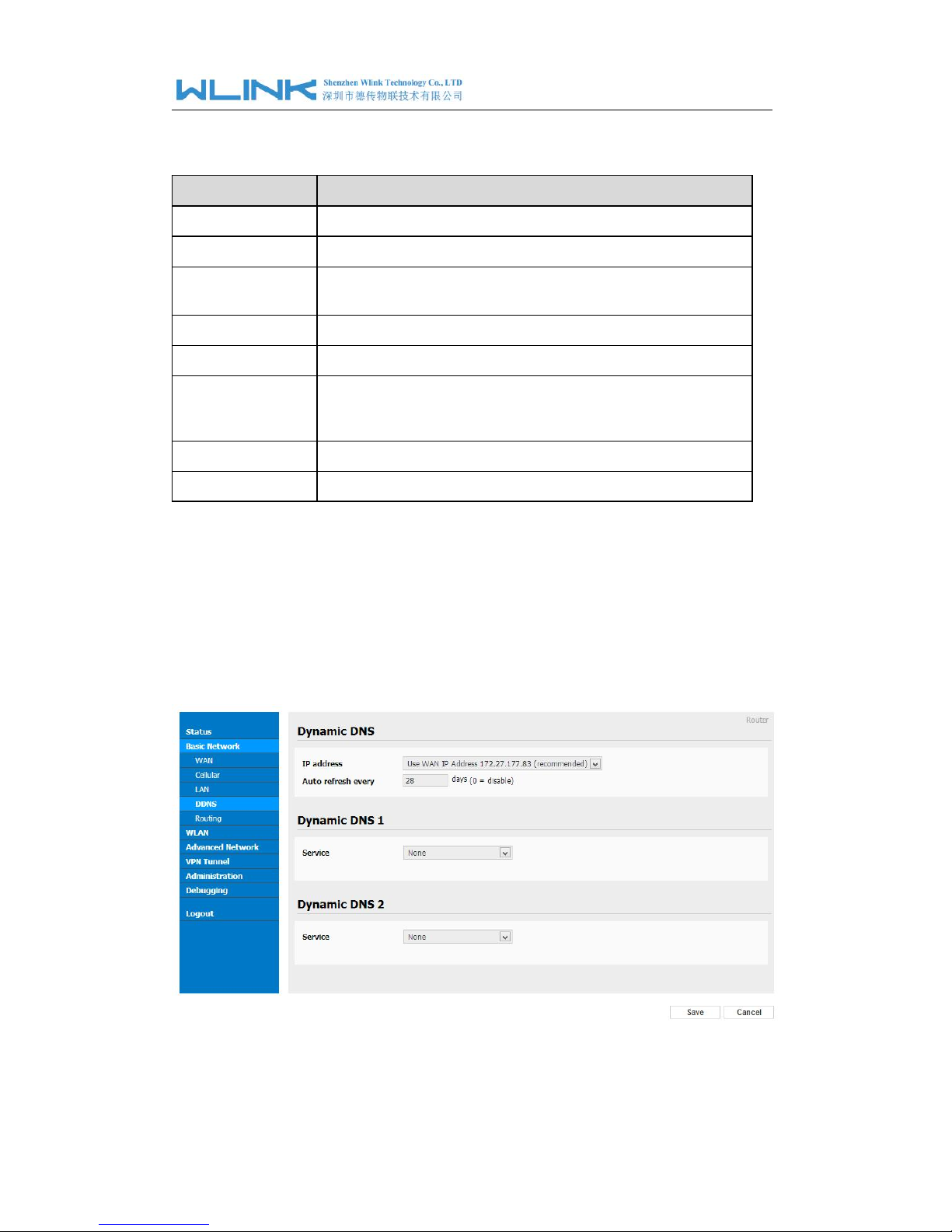
3.2.4 Dynamic DNS Setting
Step 1 Basic Network->DDNS to enter the DDNS setting page.
WL-G510 Series Router User Manual
17
Figure 3-4
Dynamic DNS Setting
Table 3-3 DDNS Setting Instruction
parameter
Instruction
IP address
Default is standard DDNS protocol, for customized protocol, please
contact Wlink engineer. Usually, use default IP 0.0.0.0
Auto refresh
time
Set the interval of the DDNS client obtains new IP, suggest 240s or
above
Service
provider
Select the DDNS service provider that listed.
Step 2 Please Click “Save“ to finish.
----End
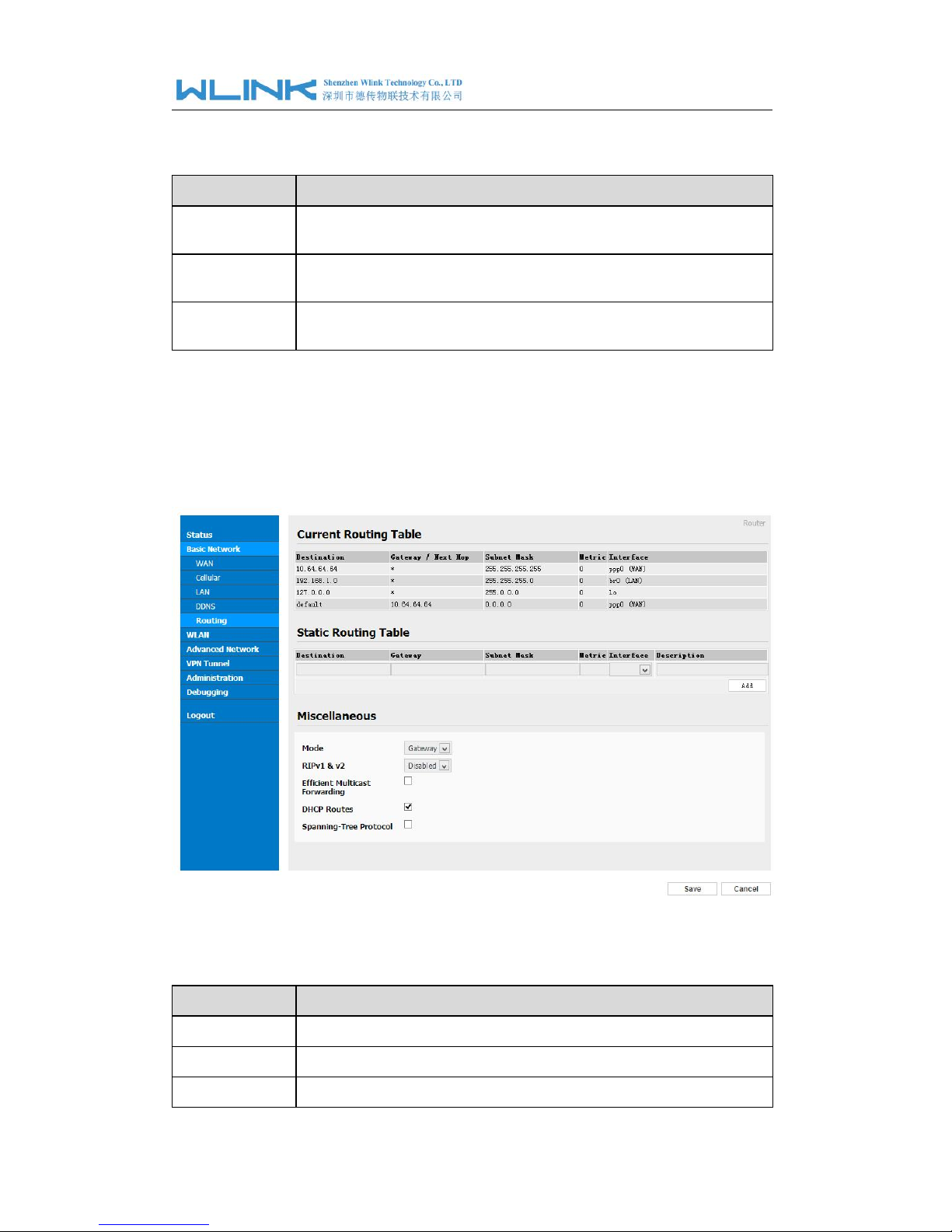
3.2.5 Routing Setting
Step 1 Basic Network->Routing to enter the DDNS setting GUI.
Figure 3-5
Routing Setting
Table 3-4 Routing Setting Instruction
Parameter
Instruction
Destination
Router can reach the destination IP address.
Gateway
Next hop IP address which the router will reach
Subnet Mask
Subnet mask for destination IP address
WL-G510 Series Router User Manual
18
Parameter
Instruction
Metric
Metrics are used to determine whether one particular route should
be chosen over another.
Interface
Interface from router to gateway.
Description
Describe this routing name.
Step 2 Please Click “ Save “ to finish.
3.3 WLAN Setting
It’s mainly for router which support Wi-Fi, you can modify and configure WLAN parameter
through Web GUI, below is the common setting
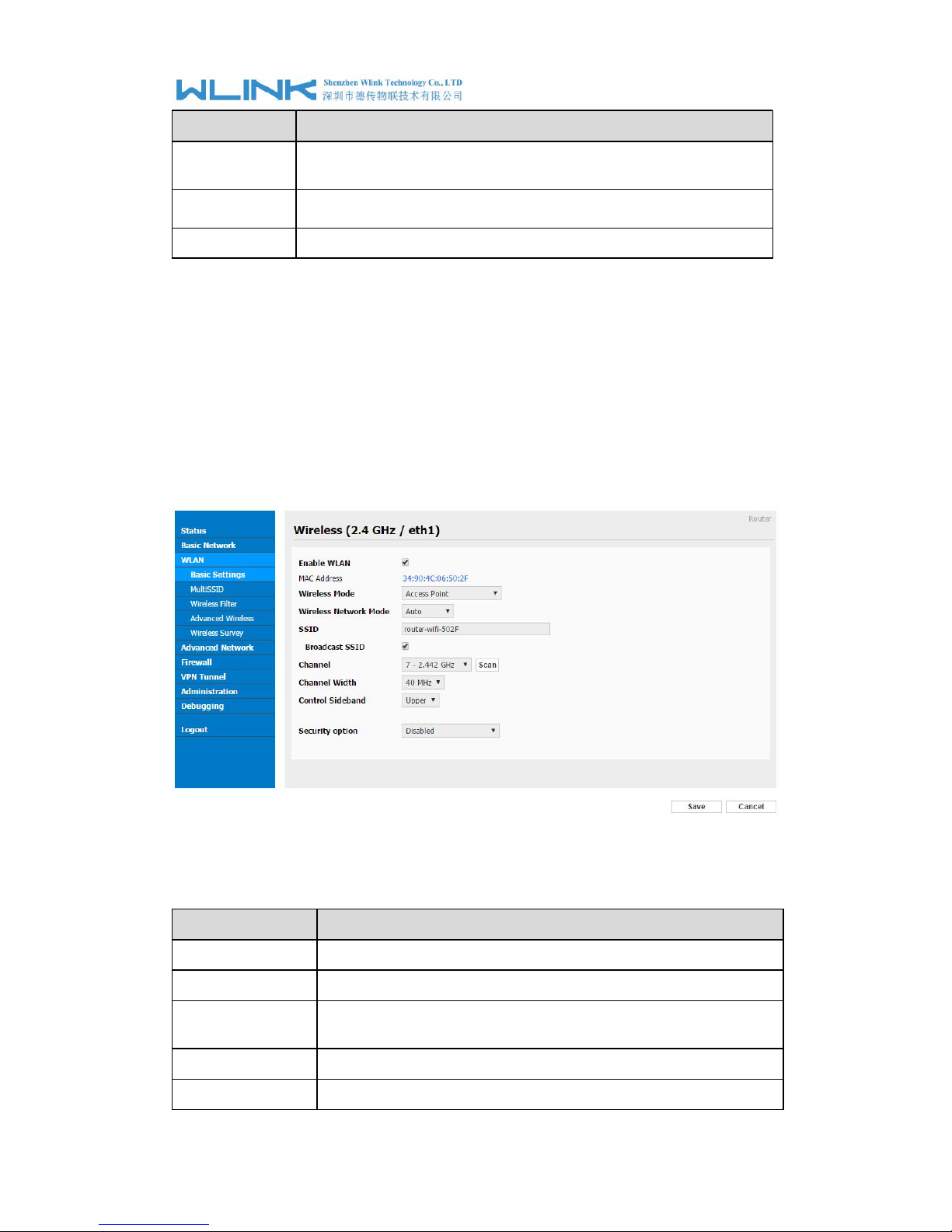
3.3.1 Basic Setting
Step 1 WLAN->Basic Setting to configure relative parameter
Figure 3-6 WLAN Basic Settings GUI
Table 3-5 Basic Setting Instruction
Parameter
Instruction
Enable wireless
Enable or Disable the Wireless
Wireless mode
Support AP, AP+WDS, Bridge, Client, WDS
Wireless Network
protocol
Support Auto, IEEE 11b/g/n optional
SSID
The default is router, can be modified as per application.
Channel
The channel of wireless network, suggest keep the default
WL-G510 Series Router User Manual
19
Parameter
Instruction
Channel Width
20MHZ and 40MHZ alternative
Security
Support various encryption method
Step 2 Please click “Save” to finish.
----End
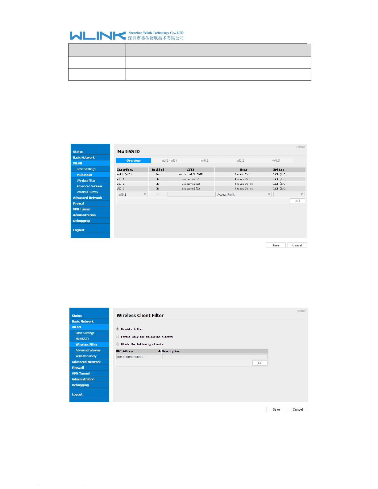
3.3.2 Wireless Filter Setting
Step 1 WLAN > MultiSSID
3.3.3 Wireless Filter Setting
Step 1 WLAN > Wireless Filter
Figure 3-7 Wireless Client Filter Setting GUI
The Wireless Filter enable to set the permitted client or prohibit the specific client to
WL-G510 Series Router User Manual
20
connect the WiFi, However, this feature is invalid for wired connection application.
Table 3-6 ”Wireless Client Filter” Setting Instruction
Parameter
Instruction
Disable Filter
Choose to disable
Permit on the
following client
Only allow the listed MAC address to connect to router by wireless
Block the follow
Client
Prevent the listed MAC address to connect to router by wireless
Step 2 Please click ”save” to finish
----End
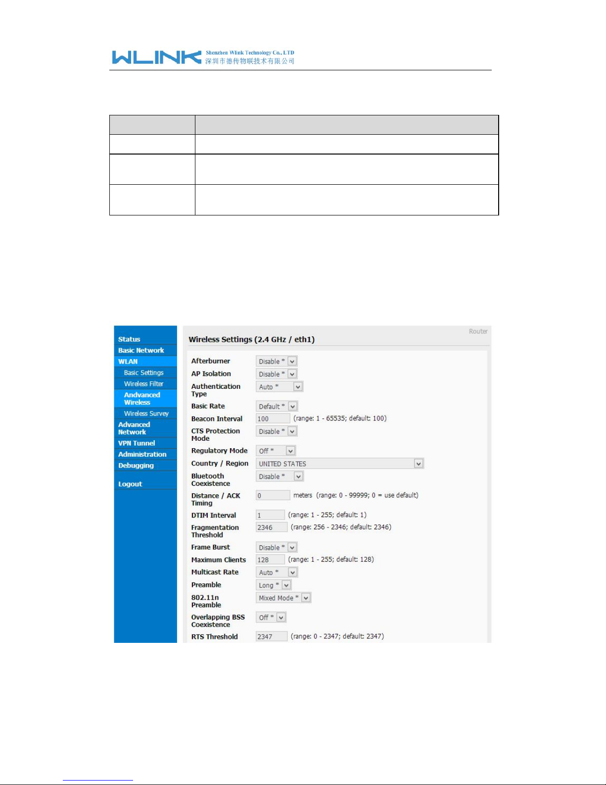
3.3.4 Advanced Wireless Setting
Step 1 WLAN> Advanced Wireless to check or modify the relevant parameter.
Figure 3-8 Advanced Wireless Setting GUI
Step 2 Please click ”save” to finish.
 Loading...