


User Manual
---Apply to WL-G500 Series Industrial 4G/3G Router
V2.3
http://www.wlink-tech.com
Feb, 2019

Industrial Cellular Gigabit Router User Manual
www.wlink-tech.com
1
Shenzhen WLINK Technology Company Limited
Add:
3F, Yiben Building, Chaguang Road, Xili, Nanshan District, China,
518054
Web:
http://www.wlink-tech.com
Service Email:
support@wlink-tech.com
Tel:
86-755-86089513
Fax:
86-755-26059261
Copyright © Shenzhen WLINK Technology Company Limited 2012
Without our written approval, Anyone can’t extract, copy whole or part of content of this file and
can’t spread out in any format.
~
2019
Caution
Due to product updates or functional upgrading, we may renew the content of this file, and this
file only for reference. All statement, information, suggestion .etc in this file does not compose
any form of guarantee and we WLINK reserves the right of final explanation.

Industrial Cellular Gigabit Router User Manual
www.wlink-tech.com
2
Contents
1 Product Introduction
1.1 Product overview
1.2 Product Appearance
1.3 Typical Application Diagram
1.4 Features
2 Hardware Installation
2.1 Panel:
2.2 LED Status
2.3 Dimension
2.4 How to Install
3 Router Configuration
...................................................................................................................................
.....................................................................................................................
..............................................................................................................................
....................................................................................................................
..........................................................................................................................
...........................................................................................................................
......................................................................................................................
..................................................................................................................
...............................................................................................................
..........................................................................................................
.............................................................................................
4
4
4
5
5
7
7
8
9
9
11
3.1 Local Configure
3.2 Basic Configuration
3.3 WLAN Setting
3.4 Advanced Network Setting
3.5 VPN Tunnel
3.6 Firewall
3.7 System Management
3.8 Debugging Setting
..............................................................................................................................
................................................................................................................
.........................................................................................................
...................................................................................................................
.......................................................................................................................
......................................................................................................
...........................................................................................................
.............................................................................................
11
12
18
21
30
32
33
47

Industrial Cellular Gigabit Router User Manual
www.wlink-tech.com
3
3.9 “RST” Button for Restore Factory Setting
4 Configuration Instance
4.1 Captive Portal
4.2 GPS Settings
...............................................................................................................
...................................................................................................................
....................................................................................................................
...................................................................
49
50
50
53
Industrial Cellular Gigabit Router User Manual
www.wlink-tech.com
4
1
Product Introduction
1.1
Product overview
1.2 Product Appearance
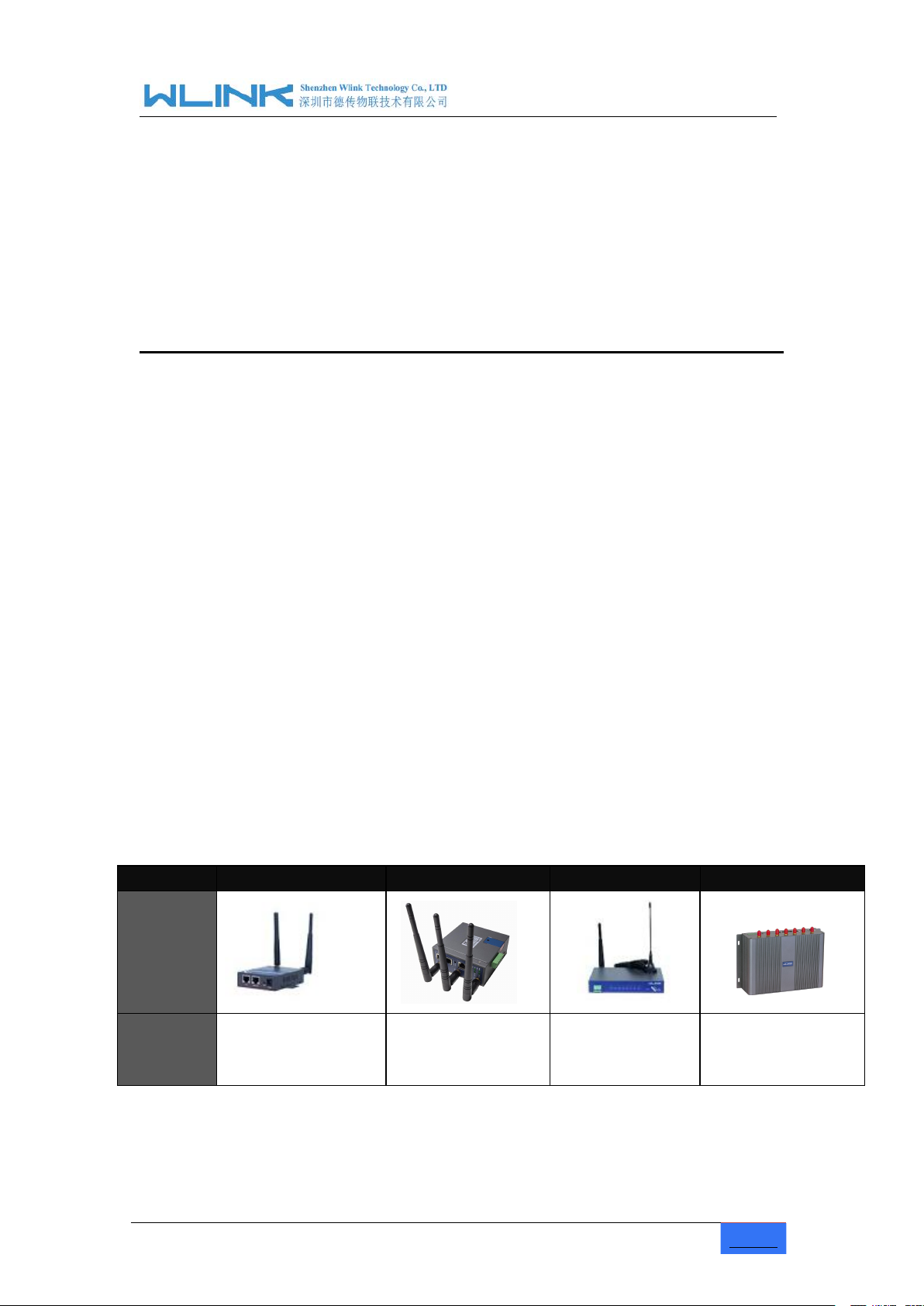
Table 1-1 WLINK Router Appearance
Series
R200
R210
R520
G500
Appearance
Ports
1*LAN
1*WAN
2*LAN
3*I/0
1*WAN + 4*LAN +
GPS or WLAN(11n 1T1R)
4*LAN
1*SD
1*USB
WL-G500 is the rugged industrial cellular router which can work on 4G/3G cellular network
to provide reliable, secure and high speed wireless connectivity, it is built-in one of the
world's leading ARM Cortex A9 Dual Core 800MHz CPU, supporting Wi-Fi 802.11N and
A/C. G500's heavy-duty design caters for transportation and mobile deployments such as
Wi-Fi bus, Wi-Fi on board and other Public transit.
WLINK G500 equips with 4xGigabit Ethernet switch, serial port, I/O, USB as well as a
variety of configuration option including GPS, SD Slot. It offers redundant SIM Slot for
automatic switching for reliable network, plus terminal block power capability. VPN
features also can be configured in WLINK router, allowing you to utilize virtual private
network service through a 4G/3G wireless router and built for stresses and workload of a
modern industrial or commercial environment.
Industrial Cellular Gigabit Router User Manual
www.wlink-tech.com
5
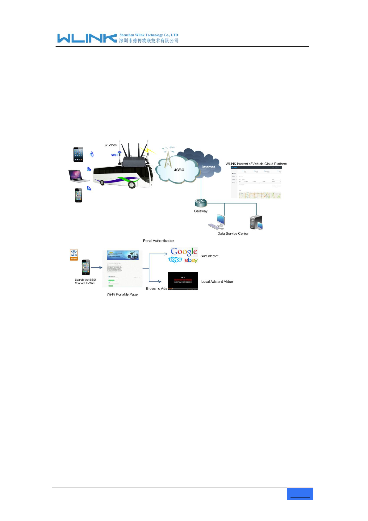
1.3 Typical Application Diagram
Figure 1-1 Network Topology
1.4
Features
Various cellular module optional, LTE/HSPA+/EVDO optional
Support IEEE802.11b/g/n&802.11a/c Wi-Fi AP function, extended support to
Support virtual data and private network(APN/VPDN)
Support on-demand dialing, include timing on/off-line, voice or SMS control
Support TCP/IP protocol stack, support Telnet, HTTP, SNMP, PPP, PPPoE, etc.,
WL-G500 4G router is installed in bus/boat/train to provide stable and fast Wi-Fi N&AC
network. The captive portal page will be pop-up in mobile phone/Pad/laptop when passengers
connect Wi-Fi SSID. Passengers might browse local advertisements and watch local video in
the captive port page. If completed Wi-Fi authentication in captive portal page, passengers
will be easily and conveniently surf internet to browse news, share journey beauty in
Facebook, listen to music, watch movies and so on.
Wi-Fi terminal, WDS bridging, support WEP, WPA/WPA2 Personal/Enterprise,
TKIP/AES, etc., Authenticated encryption mode
on/off-line, data trigger online or link idle offline
network protocol

Industrial Cellular Gigabit Router User Manual
www.wlink-tech.com
6
Support VPN Client(PPTP, L2TP),optional support Open VPN, IPSec, HTTPs,
Provide friendly user interface, use normal web internet explorer to easily
Optional IPv6 protocol stack
Optional support M2M terminal management platform
WDT watchdog design, keep system stable
Customization as customer’s demand
SSH, etc. advanced VPN function
configure and manage, long-distance configure Telnet/SSH + CLI
Industrial Cellular Gigabit Router User Manual
www.wlink-tech.com
7
2 Hardware Installation
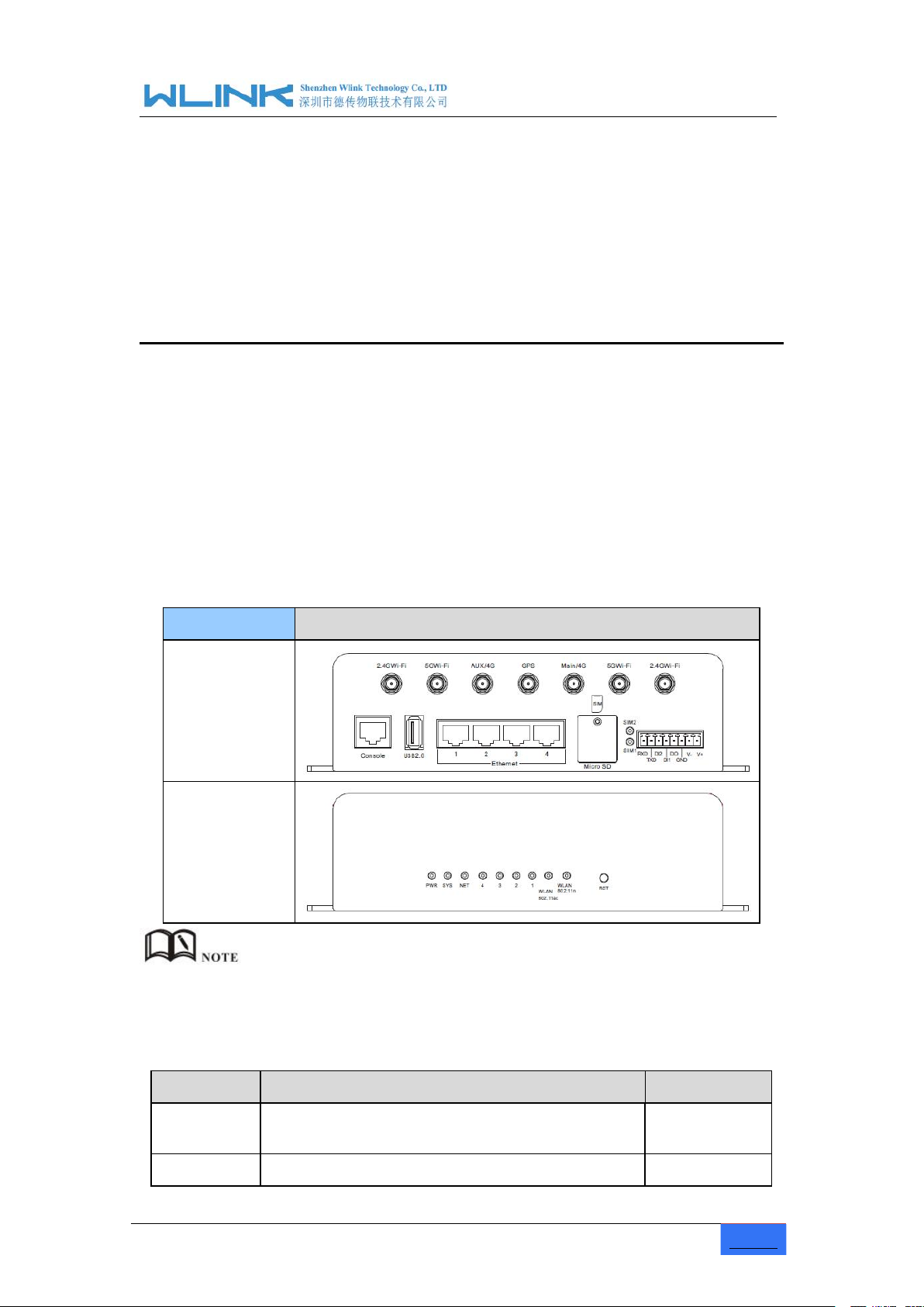
2.1 Panel:
Table 2-1 WL-G500 Structure
WLINK Tech.
WL-G500 series
Front
Rear
Table 2-2 Router Interface
Port
Instruction
Remark
USIM
Plug type SIM Slot, support 1.8/3V/5V automatic
detection
SD
Extra SD, 8G~128G optional
This chapter is mainly for installation introduction, there would be some difference
between the scheme and real object. But the difference doesn’t have any influence to
products performance.
There are some different for Antenna interface and indicator light for the
expandable Wi-Fi, GPS series.
Industrial Cellular Gigabit Router User Manual
www.wlink-tech.com
8
Port
Instruction
Remark
Main/Aux
4G
4G antenna, SMA connector, 50Ω
WIFI
2.4&5G Wi-Fi antenna, SMA connector, 50Ω
GPS
GPS antenna, SMA connector, 50Ω
Optional
LAN
10/100Base-TX,MDI/MDIX self-adaption,
G500: 4*LAN
RST
Reset button,(press on button 5 seconds)
PWR
Power connector
5 ~ 26V DC
USB
USB2.0
Console
Debugging information
RS232/RS4
85
Four pin serial port, suitable for collection device
with RS-232 or RS-485 interface, for wireless data
transmission, CON for debug test.
R20 serial port
and WAN port
multiplex
2.2
LED Status
Table 2-3 Router LED indictor Status
silk-screen
Indicator
Note
NET
Color
Green
Strong Signal
Orange
Normal Signal
Red
Weak Signal
Status
Quick Blinking
(0.5s)
Dialing
Slow Blinking (2s)
3G online
Solid light
4G online
WLAN
Green
Solid light
WLAN port enable, but no data sending.
Green
Blinking quickly
Data is in transmitting
Green
Off
WLAN port disable
LAN
Green
Solid light
Connection ok
Green
Blinking
Data Sending
Green
Off
Not connection
PWR
Green
Solid light
Power supply
Industrial Cellular Gigabit Router User Manual
www.wlink-tech.com
9
silk-screen
Indicator
Note
SYS
Green
Solid light
System operation
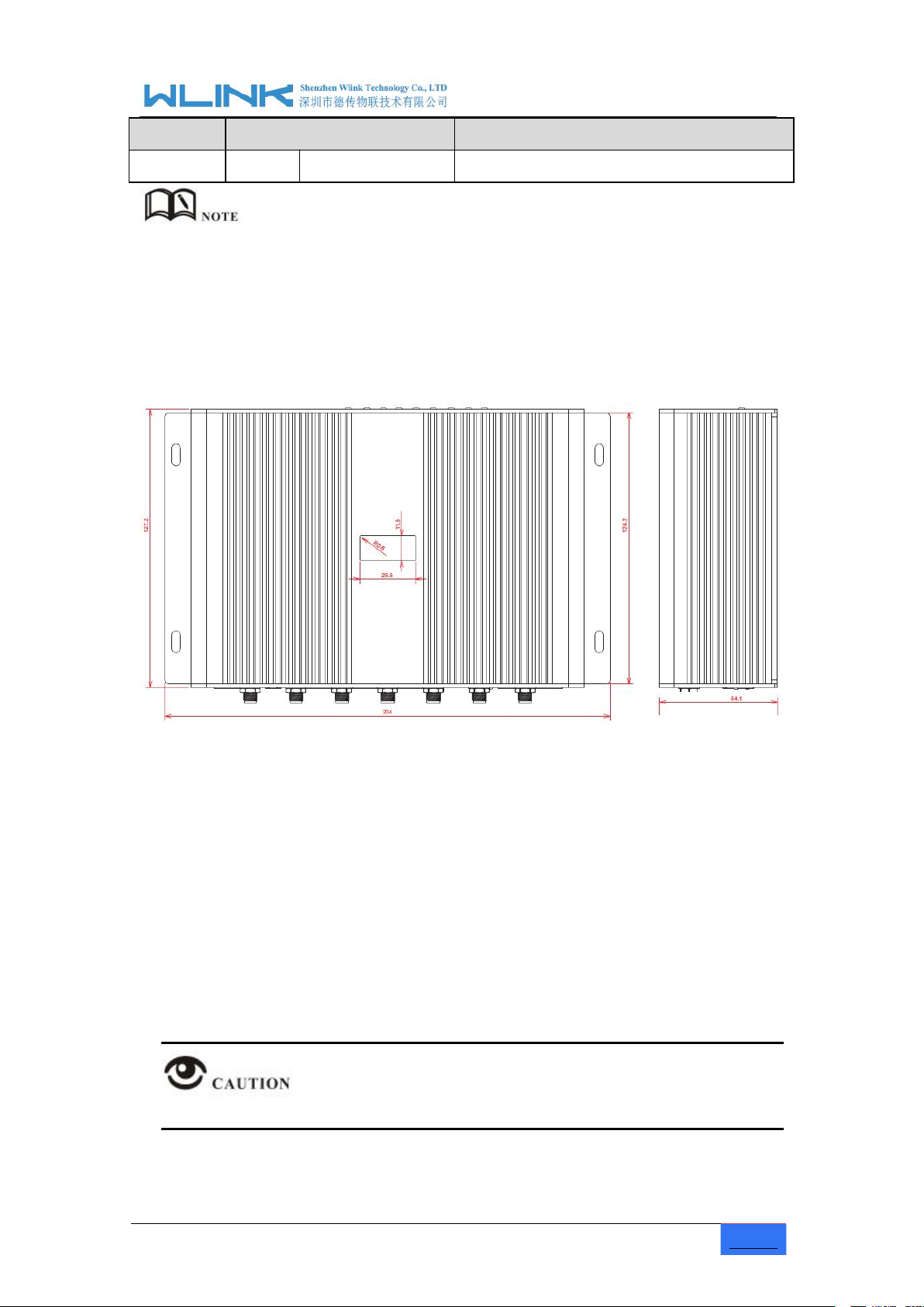
2.3
Dimension
2.4
How to Install
There are some difference among the LED indicator of expandable Wi-Fi, GPS
function and single module/double SIM, double module/double SIM series
products.
G500 Series Router Dimension Figure
2.4.1 SIM/UIM card install
If use dual SIM/UIM card router, you may need insert dual SIM before configure it. After
installation, please follow below steps to connect the router.
Before connecting, please disconnect any power resource of router
Industrial Cellular Gigabit Router User Manual
www.wlink-tech.com
10
Step 1 Check antenna connection.
Step 2 Check SIM/UIM card, confirm SIM/UIM card is available.
Step 3 Power on the industrial Router
2.4.2 Ethernet Cable Connection
Use the Ethernet cable to connect the cellular Router to computer directly, or transit by a
switch.
2.4.3 Serial Port Connection
If you want to connect the router via serial port to laptop or other devices, you should
prepare a serial port or RJ45 cable, this cable is optional. One end connect to computer
serial port, the other end connects the console port of the router
Before connecting, please disconnect any power resource of router
2.4.4 Power Supply
In order to get high reliability, WLINK Series Router adapt supports wide voltage input
range: +5V~+36VDC, support hot plug and complex application environment.
2.4.5 Review
After insert the SIM/UIM card, connect Ethernet cable and necessary antenna, connect
power cable.
Please connect the antenna before connect the power cable, otherwise the signal
maybe poor because of impedance mismatching.
Notice:
----END

Industrial Cellular Gigabit Router User Manual
www.wlink-tech.com
11
3 Router Configuration
3.1 Local Configure
Step 1 Click
“start > control panel”,find “Network Connections” icon and double click it to
Figure 3-2
Network Connection
Step 2
Obtain a IP address automatically or set up IP address,192.168.1.xxx(XXX can be
Step 3
Run an Interneft Explorer and input “
http://192.168.1.1
”, to enter identify page.
This Chapter introduces the parameter configuration of the router, the router can be
configured via web internet explorer, Firefox, or chrome. Here we take Internet Explorer
9.0 as sample.
The router supports to be configured by local Ethernet port, you could specify a static IP or
DHCP get IP for your computer. The default IP address is 192.168.1.1 ,subnet mask is
255.255.255.0, please refer to followings:
enter, select “Local Area Connection” corresponding to the network card on this
page. Refer to the figure below.
any number between 2~254)

Industrial Cellular Gigabit Router User Manual
www.wlink-tech.com
12
Figure 3-3 User Identify Interface
3.2
Basic Configuration
User should use the default user name and password when log in for the first time
----END
Different software version have different web configuration interface, below take G500
2.6.0.1 version as example.
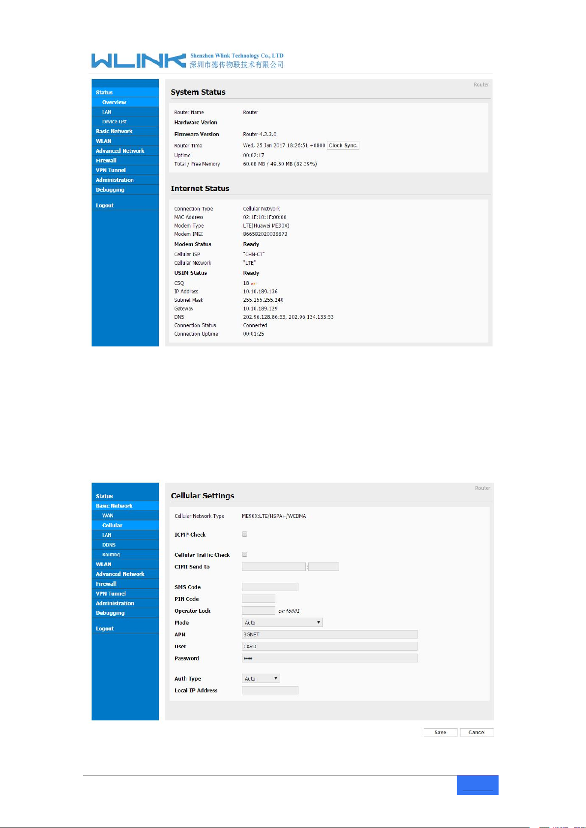
After visit the WEB interface, you can check the current status of Router, or modify router
configuration via web interface, below is the introduction for the common setting.
Industrial Cellular Gigabit Router User Manual
www.wlink-tech.com
13
Figure 3-4 Router Status GUI
3.2.1 Cellular Network Configure
Step 1 Single Click Basic Network-> Cellular, you can modify relevant parameter
according to the application.
Industrial Cellular Gigabit Router User Manual
www.wlink-tech.com
14
Figure 3-1
Cellular Settings GUI
Table 3-1 Cellular Setting Parameter Instruction
Parameter
Instruction
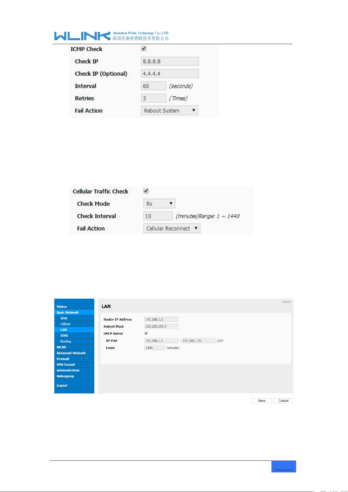
ICMP check
To enable or disable ICMP check rules. Enable the ICMP check
and setup a reachable IP address as destination IP. Once
ICMP check failed, router will reconnect/reboot system as
optional.
Cellular Traffic Check
There is Rx/Tx as options. Once no Rx/Tx data, router will
router will reconnect/reboot system as options.
CIMI Send
Send CIMI to defined IP and port by TCP protocol.
SMS Code
Remotely control router by SMS. Router just identify the correct
SMS code as configured.
Pin Code
Some SIM cards are locked with a Personal Identification
Number (PIN) code to prevent misuse if they are lost or stolen.
Operator Lock
Lock router for a specified operator via MCC/MNC code.
Connect Mode
Auto.Router will automatically connect 3G/4G network and
keep 4G in prior.
LTE. Router will connect 4G only.
3G. Router will connect 3G only.
APN
APN, provided by local ISP, usually CDMA/EVDO network do
not need this parameter.
User
SIM card user name is provided by ISP
Password
SIM card password is provided by ISP
Auth Type
Support PAP/Chap/MS-Chap/MS-Chapv2
Local IP Add
Assigned SIM IP from operator.
【ICMP Check】
Enable ICMP, Router will automatically check whether the defined IP address is
reachable per 60s. If the IP address is unreachable and ICMP check is timeout at
the first time, it will check 2 times every 3 seconds. If the third time is still failed, the
router will redial.
The ICMP Check IP is a public IP or company server IP address.
Industrial Cellular Gigabit Router User Manual
www.wlink-tech.com
15
Step 2 After Setting, please click “save” icon.
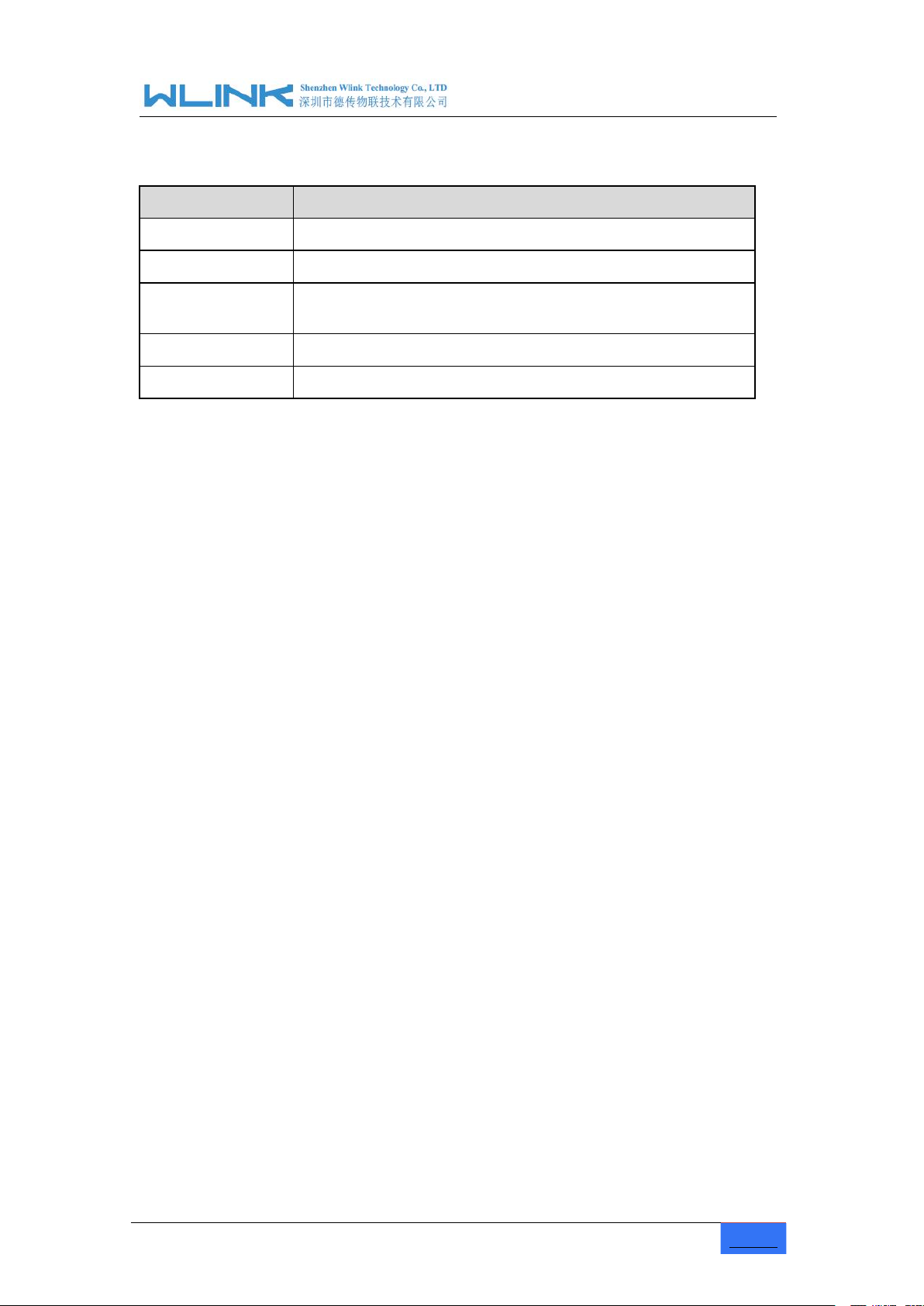
3.2.2 LAN Setting
Step 1 Single Click “ Basic Network>LAN” to enter below interface
Cellular Traffic Check
【
Check Mode】there are Rx(Receive), Tx(Transmission) and Rx/Tx check modes.
【
【Rx】Router will check the 3G/LTE cellular receiver traffic. If no receiver traffic within
the defined check interval, the router will implement the specified action reconnect
or reboot.
】
----End
www.wlink-tech.com
16
Figure 3-2
LAN Setting GUI
Table 3-2 LAN Setting Instruction
Parameter
Instruction
Router IP Address
Router IP address, default IP is 192.168.1.1
Subnet Mask
Router subnet mask, default mask is 255.255.255.0
DHCP
Dynamic allocation IP service, after enable, it will show the
IP address range and options of lease
IP Address Range
IP address range within LAN
Lease
The valid time
Step 2 After setting, please click “save” to finish, the device will reboot.
----End
Industrial Cellular Gigabit Router User Manual

Industrial Cellular Gigabit Router User Manual
www.wlink-tech.com
17
3.2.3 Dynamic DNS Setting
Step 1 Single click “Basic Network->DDNS to enter the DDNS setting GUI.
Figure 3-3
Dynamic DNS Setting
Table 3-3 DDNS Setting Instruction
parameter
Instruction
IP address
Default is standard DDNS protocol, for customized protocol, please
contact WLINK engineer. use default IP 0.0.0.0 as usually.
Auto refresh
time
Set the interval of the DDNS client obtains new IP, suggest 5mins or
above
Service
provider
Select the DDNS service provider that listed.
Step 2 Please Click “Save“ to finish.
3.2.4 Routing Setting
Step 1 Single click “Basic Network->Routing to enter the DDNS setting GUI.
----End

Industrial Cellular Gigabit Router User Manual
www.wlink-tech.com
18
Figure 3-4 Routing Setting
Table 3-4 Routing Setting Instruction
Parameter
Instruction
Destination
Router can reach the destination IP address.
Gateway
Next hop IP address which the router will reach
Subnet Mask
Subnet mask for destination IP address
Metric
Metrics are used to determine whether one particular route should
be chosen over another.
Interface
Interface from router to gateway.
Description
Describe this routing name.
Step 2 Please Click “ Save “ to finish.
3.3
WLAN Setting
3.3.1 Basic Setting
Step 1 Click “WLAN->Basic Setting” to configure relative parameter
It’s mainly for router which support Wi-Fi, you can modify and configure WLAN
parameter through Web GUI, below is the common setting

Industrial Cellular Gigabit Router User Manual
www.wlink-tech.com
19
Figure 3-5 WLAN Basic Settings GUI
Table 3-5
Table 3-6
Table 3-7
Table 3-8
Table 3-9
Table 3-10 Basic Setting Instruction
Parameter
Instruction
Enable wireless
Enable or Disable the Wireless
Wireless mode
Support AP, AP+WDS, Bridge, Client, WDS
Wireless Network
protocol
Support Auto, IEEE 11b/g/n optional
SSID
The default is router, can be modified as per application.
Channel
The channel of wireless network, suggest keep the default
Channel Width
20MHZ and 40MHZ alternative
Security
Support various encryption method
Step 2 Please click “Save” to finish.
3.3.2 Wireless Filter Setting
Step 1 Single click “WLAN > Wireless Filter”.
----End

Industrial Cellular Gigabit Router User Manual
www.wlink-tech.com
20
Figure 3-6 Wireless Client Filter Setting GUI
Table 3-11 ”Wireless Client Filter” Setting Instruction
Parameter
Instruction
Disable Filter
Choose to disable
Permit on the
following client
Only allow the listed MAC address to connect to router by wireless
Block the follow
Client
Prevent the listed MAC address to connect to router by wireless
Step 2 Please click ”save” to finish
3.3.3 Wireless Survey
Step 1 Please click “WLAN> Wireless Survey” to check survey.
The Wireless Filter enable to set the permitted client or prohibit the specific client to
connect the WiFi, However, this feature is invalid for wired connection application.
----End

www.wlink-tech.com
21
Figure 3-7 Wireless Survey Setting GUI
----End
3.4 Advanced Network Setting
3.4.1 Port Forwarding
Step 1 Please click “Advanced Network > Port Forwarding” to enter the GUI, you may
Industrial Cellular Gigabit Router User Manual
modify the router name, Host name and Domain name according to the
application requirement.

www.wlink-tech.com
22
Figure 3-8
Port Forwarding GUI
Table 3-12 “Port Forwarding” Instruction
Parameter
Instruction
Protocol
Support UDP, TCP, both UDP and TCP
Src. Address
Source IP address. Forward only if from this address.
Ext. Ports
External ports. The ports to be forwarded, as seen from the
WAN.
Int. Port
Internal port. The destination port inside the LAN. If blank,
the destination port is the same as Ext Ports. Only one port
per entry is supported when forwarding to a different
internal port.
Int. Address
Internal Address. The destination address inside the LAN.
Description
Remark the rule
Step 2 Please click ”save” to finish
----End
3.4.2 Port Redirecting
Step 1 Please click “Advanced Network > Port Redirecting” to enter the GUI, you may
Industrial Cellular Gigabit Router User Manual
modify the router name, Host name and Domain name according to the
application requirement.

www.wlink-tech.com
23
Figure 3-9
Port Forwarding GUI
Table 3-13 “Port Redirecting” Instruction
Parameter
Instruction
Protocol
Support UDP, TCP, both UDP and TCP
Int Port
Internal port.
Dst. Address
The redirecting IP address.
Ext. Ports
External port for redirection.
Description
Remark the rule
Step 2 Please click ”save” to finish
----End
3.4.3 DMZ Setting
Step 1 Please click “Advanced Network> DMZ” to check or modify the relevant
Figure 3-10
DMZ GUI
Table 3-14 “DMZ” Instruction
parameter
Instruction
Destination
Address
The destination address inside the LAN.
Source
Address
Restriction
If no IP address inside, it will allow all IP address to access.
If define IP address, it will just allow the defined IP address
to access.
Industrial Cellular Gigabit Router User Manual
parameter.

www.wlink-tech.com
24
parameter
Instruction
Leave Remote
Access
Step 2 Please click ”save” to finish
----End
3.4.4 Triggered Setting
Step 1 Please click “Advanced Network> Triggered” to check or modify the relevant
Figure 3-11
Triggered GUI
Table 3-15 “Triggered” Instruction
parameter
Instruction
Protocol
Support UDP, TCP, both UDP and TCP
Triggered Ports
Trigger Ports are the initial LAN to WAN "trigger".
Transferred
Ports
Forwarded Ports are the WAN to LAN ports that are
opened if the "trigger" is activated.
Note
Port triggering opens an incoming port when your
computer is using a specified outgoing port for specific
traffic.
Step 2 Please click ”save” to finish.
Industrial Cellular Gigabit Router User Manual
parameter.
----End

www.wlink-tech.com
25
3.4.5 Captive Portal Setting
Step 1 Please click “Advanced Network> Captive Portal” to check or modify the relevant
parameter.
Figure 3-12 Captive Portal Setting GUI
Table 3-16 “Serial App” Instruction
Parameter
Instruction
Enable
Enable Captive portal feature.
Auth Type
Reserved.
Web Root
Choose captive portal file storage path.
Default: Captive portal file is in the firmware as default.
In-storage: Captive portal file is in router’s Flash.
Ex-storage: Captive portal file is in extended storage such as SD
card.
Web Host
Configure domain name for the captive portal access. For example,
Configure as wlink.tech.com, we might directly access to captive
portal page in the website as wlink.tech.com
Portal Host
Reserved.
Logged Timeout
Maximum time user has connectivity. User need to re-login Captive
Portal page after defined time.
Idle Timeout
Maximum time user has connectivity if no network activity from Wi-Fi
User.If User need to re-login Captive page to surf internet.
Industrial Cellular Gigabit Router User Manual

www.wlink-tech.com
26
Parameter
Instruction
Ignore LAN
If enabled, LAN devices will bypass the Captive Portal page.
Redirecting
Router will redirect to the defined link after accepting the terms and
conditions on the Captive Portal page.
MAC Whitelist
No captive portal page for Wi-Fi device.
Download QoS
Enable to apply the Download and Upload per user limits.
Upload Qos
Maximum download speed available to each user.
----End
3.4.6 GPS Setting
Step 1 Please click “Advanced Network> GPS” to check or modify the relevant
Figure 3-13
GPS Setting GUI
Table 3-17 “GPS” Instruction
parameter
Instruction
GPS Mode
Enable/Diable
GPS Format
NMEA and M2M_FMT(WLINK)
Server IP/Port
GPS server IP and port
Industrial Cellular Gigabit Router User Manual
parameter.

Industrial Cellular Gigabit Router User Manual
www.wlink-tech.com
27
parameter
Instruction
Heart-Beat
If choose M2M_FMT format, heart-beat ID will be packed
itnto GPS data.
Interval
GPS data transmit as the interval time.
Step 2 Please click ”save” to finish
Field
No.
Name
Format
Example
Description
1
Router ID
String
0001_R081850
ac
0001 customizable product
ID.
_R router indicator.
081850ac Last 8digits of
routers MAC address.
2
gps_date
yymmdd
150904
Date in year,month,day
3
gps_time
hhmmss.ss
s
043215.0
UTC Time, Time of position fix.
4
gps_use
numeric
06
Satellites Used, Range 0 to 12.
5
gps_latitude
ddmm.mm
mm
2234.248130
Latitude, Degrees + minutes.
6
gps_NS
character
N
N/S Indicator,N=north or
S=south.
7
gps_longitude
ddmm.mm
mm
11356.626179
Longitude, Degrees + minutes.
8
gps_EW
character
E
E/W indicator, E=east or
W=west.
9
gps_speed
numeric
0.0
Speed over ground, units is
km/h.
10
gps_degrees
numeric
91.5
Course over ground, unit is
M2M_FMT Format as below.
1. GPS data structure.
Router ID, gps_date, gps_time, gps_use, gps_latitude, gps_NS, gps_longitude, gps_EW,
gps_speed, gps_degrees, gps_FS, gps_HDOP, gps_MSL
2. Example
0001_R081850ac,150904,043215.0,06,2234.248130,N,11356.626179,E,0.0,91.5,1,1.2,9
7.5
3. GPS data description

www.wlink-tech.com
28
degree.
11
gps_FS
digit1Position Fix Status Indicator,
12
gps_HDOP
numeric
1.2
HDOP, Horizontal Dilution of
Precision
13
gps_MSL
numeric
97.5
MSL Altitude, units is meter.
3.4.7 UPnp/NAT-PMP Setting
Step 1 Please click “Advanced Network> Upnp/NAT-PMP” to check or modify the
relevant parameter.
Figure 3-14
UPnp/NAT-PMP Setting GUI
Step 2 Please click ”save” to finish.
3.4.8 VRRP Setting
Step 1 Please click “Advanced Network> Static DHCP” to check or modify the relevant
Industrial Cellular Gigabit Router User Manual
parameter.

www.wlink-tech.com
29
Figure 3-15 VRRP Setting GUI
Step 2 Please click ”save” to finish.
----End
3.4.9 Static DHCP Setting
Step 1 Please click “Advanced Network> Static DHCP” to check or modify the relevant
Figure 3-16 Static DHCP Setting GUI
Step 2 Please click ”save” to finish.
Industrial Cellular Gigabit Router User Manual
parameter.
----End

Industrial Cellular Gigabit Router User Manual
www.wlink-tech.com
30
3.5 VPN Tunnel
3.5.1
GRE Setting
Step 1 Please click “VPN Tunnel> GRE” to check or modify the relevant parameter.
Figure 3-17 GRE Setting GUI
Table 3-18 “GRE” Instruction
Parameter
Instruction
Idx
GRE tunnel number
Tunnel Address
GRE Tunnel local IP address which is a virtual IP
address.
Tunnel Source
Router’s 3G/WAN IP address.
Tunnel Destination
GRE Remote IP address. Usually a public IP address
Keep alive
GRE tunnel keep alive to keep GRE tunnel connection.
Interval
Keep alive interval time.
Retries
Keep alive retry times. After retry times, GRE tunnel
will be re-established.
Description
Step 2 Please click ”save” to finish.
3.5.2 VPN Client Setting
Step 1 Please click “VPN Tunnel> VPN Client” to check or modify the relevant parameter.
----End

Industrial Cellular Gigabit Router User Manual
www.wlink-tech.com
31
Table 3-19 “VPN Client” Instruction
parameter
Instruction
VPN Mode
VPN Mode for PPTP and L2TP
Server Address
VPN Server IP address.
User name
As the configuration requested.
Password
As the configuration requested.
Encryption
As the configuration requested.
Stateless
MPPE
As the configuration requested.
Accept DNS
As the configuration requested.
Remote Subnet
As the configuration requested.
Create NAT on
Tunnel
As the configuration requested.
MTU
MTU is 1450bytes as default
MRU
MRU is 1450bytes as default
Local IP
Address
Defined Local IP address for tunnel
Step 2 Please click ”save” to finish.
----End

www.wlink-tech.com
32
3.6 Firewall
3.6.1 IP/URL Filtering
Step 1 Please click “Firewall> IP/URL Filtering” to check or modify the relevant
parameter.
Table 3-20 “IP/URL Filtering” Instruction
Parameter
Instruction
IP/MAC/Port
Filtering
Support IP address, MAC address and port filter.
Key Word
Filtering
Support key word filter.
URL Filtering
Support URL filter.
Step 2 Please click ”save” to finish.
3.6.2 Domain Filtering
Step 1 Please click “Firewall> Domain Filtering” to check or modify the relevant
Industrial Cellular Gigabit Router User Manual
parameter.

Industrial Cellular Gigabit Router User Manual
www.wlink-tech.com
33
Figure 3-18 Domain Filtering Setting GUI
Table 3-21 “GRE” Instruction
Parameter
Instruction
Default Policy
Support black list and white list
Local IP
Address
Local IP address for LAN.
Domain
Support Domain filter.
Step 2 Please click ”save” to finish.
3.7 System Management
3.7.1 Identification Setting
Step 1 Please click ”Administrator> Identification” to enter the GUI, you may modify the
----End
router name, Host name and Domain name according to self-requirement.

Industrial Cellular Gigabit Router User Manual
www.wlink-tech.com
34
Figure 3-19 Router Identification GUI
Table 3-22 “Router Identification” Instruction
Parameter
Instruction
Router name
Default is router, can be set maximum 32 character
Host name
Default is router, can be set maximum 32 character
Domain name
Default is empty, support maximum up to 32 character, it is
the domain of WAN, no need to configure for most
application.
Step 2 Please click ”save” to finish
----End

Industrial Cellular Gigabit Router User Manual
www.wlink-tech.com
35
3.7.2 Time Setting
Step 1 Please click “Administrator> time” to check or modify the relevant parameter.
Figure 3-20 System Configuration GUI
Step 2 Please click “save to finish.
----End
If the device is online but time update is fail, please try other NTP Time Server.

Industrial Cellular Gigabit Router User Manual
www.wlink-tech.com
36
3.7.3 Admin Access Setting
Step 1 Please click “Administrator>Admin” to check and modify relevant parameter.
Figure 3-21 Admin Setting GUI
Step 2 Please click save iron to finish the setting
In this page, you can configure the basic web parameter, make it more convenient for
usage. Please note the “password” is the router system account password.
----End

www.wlink-tech.com
37
3.7.4 Schedule Reboot Setting
Step 1 Please click “Administrator>Schedule Reboot” to check and modify relevant
parameter.
Figure 3-22 Scheduler Reboot Setting GUI
Step 2 Please click save iron to finish the setting
3.7.5 Storage Setting
Step 1 Please click “Administrator>Storage” to check and modify relevant parameter.
Industrial Cellular Gigabit Router User Manual
----End

Industrial Cellular Gigabit Router User Manual
www.wlink-tech.com
38
Figure 3-23 SNMP Setting GUI
Step 2 Please click save iron to finish the setting
Upload the portal images for the Slider (0001_portal.png, 0002_portal.png, and
0003_portal.png) to the Router under the “Administration / Storage Settings” menu.
Furthermore, also might upload splash with images together.
Picture format should be .png and Picture size is less than 100Kbytes and resolution is
800*600. Picture name is 0001_portal.png, 0002_portal.png and 0003_portal.png.

www.wlink-tech.com
39
----End
3.7.6 M2M Access Setting
Step 1 Please click “Administrator>M2M Access” to check and modify relevant
Figure 3-24 M2M Access Setting GUI
Parameter
Instruction
M2M Enable
Please tick M2M option if you need this feature.
Fail Action
Restart M2M, Reboot and Redial
Product ID
Identity product in M2M platform, the Max length is 14bytes.
M2M Server
IP/Port
Configure M2M platform IP and port. The router will log in M2M
platform and establish a connection between router and M2M
platform. The connection protocol is UDP.
Heartbeat Interval
WLINK router send a heartbeat to M2M platform as report interval
time.
Heartbeat Retry
After retry times, router will implement the Fail Action.
Step 2 Please click save iron to finish the setting
Industrial Cellular Gigabit Router User Manual
parameter.
----End

www.wlink-tech.com
40
3.7.7 DI/DO Setting
Step 1 Please click “Administrator>DI/DO Setting” to check and modify relevant
parameter.
Figure 3-25
DI/DO Setting GUI
Industrial Cellular Gigabit Router User Manual
3.7.7.1 DI Configure

Industrial Cellular Gigabit Router User Manual
www.wlink-tech.com
41
Table 3-23 “DI” Instruction
Parameter
Instruction
Enable
Enable DI. Port1 is for I/O1 and Port2 is I/O2. Both I/O1 and I/O2 are
DI ports
Mode
Selected from OFF, ON and EVENT_COUNTER modes.
OFF Mode: When I/O connects to GND, it will trigger alarm.
ON Mode: When I/O does not connect to GND, it will trigger alarm.
EVENT_COUNTER Model: Enter EVENT_COUNTER mode.
Filter
Software filtering is used to control switch bounces. Input
(1~100)*100ms.
Under OFF and ON modes, WL-R210 detects pulse signal and
compares with first pulse shape and last pulse shape. If both are the
same level, WL-R210 will trigger alarm.
Under EVENT_COUNTER mode, if first pulse shape and last pulse
shape are not the same level, WL-R210 will trigger alarm according
to Counter Action setting.
Counter Trigger
Available when DI under Event Counter mode
Input from 0 to 100. (0=will not trigger alarm)
It will trigger alarm when counter reaches this value. After triggering
alarm, DI will keep counting but no trigger alarm again.
Counter Period
It’s a reachable IP address. Once the ICMP check is failed, GRE will
be established again.
Counter
Recover
it will re-count after counter trigger alarm. The value is 0~30000(*100ms).
0 means no counter.
Counter Action
HI_TO_LO and LO_TO_HI is available when DI under Event
Counter mode.
In Event Counter mode, the channel accepts limit or proximity
switches and counts events according to the ON/OFF status. When
LO_TO_HI is selected, the counter value increase when the
attached switch is pushed. When HI_TO_LO is selected, the counter
value increases when the switch is pushed and released.
Counter Start
Available when DI under EVENT_COUNTER mode. Start counting
when enable this feature.
SMS Alarm
The alarm SMS will send to specified phone group.
Each phone group include up to 2 phone numbers.
SMS Content
70 ASCII Char Max
Number 1
SMS receiver phone number.
Number 2
SMS receiver phone number.
Step 2 Please click ”save” to finish.
3.7.7.2 DO Configure

Industrial Cellular Gigabit Router User Manual
www.wlink-tech.com
42
Table 3-24 “DO” Instruction
Parameter
Instruction
Enable
1 DO as selected
Alarm Source
Digital output initiates according to different alarm source.
Select from DI Alarm, SMS Control and M2M Control. Selections can
be one or more.
DI Alarm: Digital Output triggers the related action when there is
alarm from Digital Input.
SMS Control: Digital Output triggers the related action when
receiving SMS from the number in phone book.
M2M Control: it’s not ready.
Alarm Action
Digital Output initiates when there is an alarm.
Selected from “OFF”, “ON”, “Pulse”.
OFF: Open from GND when triggered.
ON: Short contact with GND when triggered.
Pulse: Generates a square wave as specified in the pulse mode
parameters when triggered.
Power on
Status
Specify the digital Output status when power on.
Selected from OFF and ON.
OFF: Open from GND.
ON: Short contact with GND.
Keep On
Available when digital output Alarm On Action/Alarm Off Action
status is ON, input the Digital Output keep on status time.
Input from 0 to 255 seconds. (0=keep on until the next action)
Delay
Available when enable Pulse in Alarm On Action/Alarm Off Action.
The first pulse will be generated after a “Delay”.

Industrial Cellular Gigabit Router User Manual
www.wlink-tech.com
43
Parameter
Instruction
Input from 0 to 30000ms. (0=generate pulse without delay)
Low
Available when enable Pulse in Alarm On Action/Alarm Off Action.
In Pulse Output mode, the selected digital output channel will
generate a square wave as specified in the pulse mode parameters.
The low level widths are specified here.
Input from 1 to 30000 ms.
High
Available when enable Pulse in Alarm On Action/Alarm Off Action.
In Pulse Output mode, the selected digital output channel will
generate a square wave as specified in the pulse mode parameters.
The high level widths are specified here.
Input from 1 to 30000 ms.
Output
Available when enable Pulse in Alarm On Action/Alarm Off Action.
The number of pulses, input from 0 to 30000. (0 for continuous pulse
output)
SMS Trigger
Content
Available when enable SMS Control in Alarm Source.
Input the SMS content to enable “Alarm On Action” by SMS (70
ASIC II char max).
SMS Reply
Content
Input the SMS content, which will be sent after DO was triggered.
(70 ASIC II char max).
Number 1
SMS receiver phone number.
Number 2
SMS receiver phone number.
Step 3 Please click ”save” to finish.
3.7.8 Configuration Setting
Step 1 Please click “ Administrator> Back up Configuration ” to do the backup setting

Industrial Cellular Gigabit Router User Manual
www.wlink-tech.com
44
Figure 3-26 Backup and Restore Configuration GUI
Step 2 After setting the backup and restore configuration. The system will reboot
----End
Restore Default would lose all configuration information, please be careful.
automatically.

Industrial Cellular Gigabit Router User Manual
www.wlink-tech.com
45
3.7.9 System Log Setting
Step 1 Please click “Administrator> Logging” to start the configuration, you can set the file
Figure 3-27 System log Setting GUI
Step 2 After configure, please click “Save” to finish.
path to save the log (Local or remote sever).
----End

Industrial Cellular Gigabit Router User Manual
www.wlink-tech.com
46
3.7.10 Firmware upgrade
Step 1 Please click “Administrator>firmware upgrade” to open upgrade firmware tab.
Figure 3-28 Firmware Upgrade GUI
3.7.11 System Reboot
Step 1 Please click “Administrator>Reboot” to restart the router. System will popup dialog
When upgrading, please don’t cut off the power.
to remind “Yes” or “NO” before the next step.

www.wlink-tech.com
47
Step 2 If choose “yes”, the system will restart, all relevant update configuration will be
effective after reboot.
3.8 Debugging Setting
3.8.1 Logs Setting
Step 1 Please click “Debugging>Logs” to check and modify relevant parameter.
Figure 3-29
Logs GUI
Step 2 After configure, please click “Save” to finish.
3.8.2 Ping Setting
Step 1 Please click “Debugging>Logs” to check and modify relevant parameter.
Industrial Cellular Gigabit Router User Manual
----End
----End

www.wlink-tech.com
48
Figure 3-30 Ping GUI
Step 2 After configure, please click “Save” to finish.
----End
3.8.3 Trace Setting
Step 1 Please click “Debugging>Trace” to check and modify relevant parameter.
Figure 3-31
Trace GUI
Step 2 After configure, please click “Save” to finish.
Industrial Cellular Gigabit Router User Manual
----End

Industrial Cellular Gigabit Router User Manual
www.wlink-tech.com
49
3.9 “RST” Button for Restore Factory Setting
Table 3-25 System Default Instruction
Parameter
Default setting
LAN IP
192.168.1.1
LAN Subnet Mask
255.255.255.0
DHCP server
Enable
User Name
admin
Password
admin
If you couldn’t enter web interface for other reasons, you can also use this way.
For R200 Series, “RST” button is on the left or Ethernet port, for G500 Series, the button is
on the left of NET light. This button can be used when the router is in use or when the
router is turned on.
Press the “RST” button and keep more than 8 seconds till the NET light stopping blink.
The system will be restored to factory.
After reboot, the previous configuration would be deleted and restore to factory
settings.

Industrial Cellular Gigabit Router User Manual
www.wlink-tech.com
50
4 Configuration Instance
Step 1 Please click “Advanced Network> Captive Portal” to check or modify the relevant
This chapter is mainly for configured test case, there would be some difference between
the scheme and real object. But the difference doesn’t have any influence to products
performance.
4.1 Captive Portal
This feature is suitable for Wi-Fi captive portal
parameter.
1)Upload Portal file and Splash.html by local
Upload portal images and splash.html in router for the Slider (0001_portal.png,
0002_portal.png, and 0003_portal.png) to the Router under the “ Administration / Storage
Settings” menu.
Furthermore, also might upload splash with images together.

Industrial Cellular Gigabit Router User Manual
www.wlink-tech.com
51
Each Ad file just supports 3 Ad portal images. Picture format is acceptable for png/jpg and
image size is less than 100Kbytes and resolution is 800*600. Picture name is
0001_portal.png, 0002_portal.png and 0003_portal.png. Furthermore, please keep image
names the same between portal file and splash.html.

Industrial Cellular Gigabit Router User Manual
www.wlink-tech.com
52
Finally, we can see the results by connect to router WIFI
2)Modify portal file storage path

www.wlink-tech.com
53
Modify portal file storage for In-storage as below.
Step 1 Please click “Advanced Network> GPS” to view or modify the relevant parameter.
parameter
Instruction
GPS Mode
Enable/Disable
GPS Format
NMEA and M2M_FMT(WLINK)
Industrial Cellular Gigabit Router User Manual
4.2 GPS Settings
The feature is requested hardware supports GPS feature.
Table 4-2 “GPS” Instruction

Industrial Cellular Gigabit Router User Manual
www.wlink-tech.com
54
parameter
Instruction
Server IP/Port
GPS server IP and port
Heart-Beat
If choose M2M_FMT format, heart-beat ID will be packed into GPS
data.
Interval
GPS data transmit as the interval time.
Step 2 Please click “save” to finis
Step 3 Connect the GPS antenna to router GPS interface
Field
No.
Name
Format
Example
Description
1
Router ID
String
0001_R081850
ac
0001 customizable product
ID.
_R router indicator.
081850ac Last 8digits of
routers MAC address.
M2M_FMT Format as below.
1. GPS data structure.
Router ID, gps_date, gps_time, gps_use, gps_latitude, gps_NS, gps_longitude, gps_EW,
gps_speed, gps_degrees, gps_FS, gps_HDOP, gps_MSL
2. Example
0001_R081850ac,150904,043215.0,06,2234.248130,N,11356.626179,E,0.0,91.5,1,1.2,9
7.5
3. GPS data description

Industrial Cellular Gigabit Router User Manual
www.wlink-tech.com
55
2
gps_date
yymmdd
150904
Date in year,month,day
3
gps_time
hhmmss.ss
s
043215.0
UTC Time, Time of position fix.
4
gps_use
numeric
06
Satellites Used, Range 0 to 12.
5
gps_latitude
ddmm.mm
mm
2234.248130
Latitude, Degrees + minutes.
6
gps_NS
character
N
N/S Indicator,N=north or
S=south.
7
gps_longitude
ddmm.mm
mm
11356.626179
Longitude, Degrees + minutes.
8
gps_EW
character
E
E/W indicator, E=east or
W=west.
9
gps_speed
numeric
0.0
Speed over ground, units is
km/h.
10
gps_degrees
numeric
91.5
Course over ground, unit is
degree.
11
gps_FS
digit1Position Fix Status Indicator,
12
gps_HDOP
numeric
1.2
HDOP, Horizontal Dilution of
Precision
13
gps_MSL
numeric
97.5
MSL Altitude, units is meter.
 Loading...