

WJ Company HMJ7, HMJ7-PCB Datasheet
WJ Communications, Inc. • Phone: 1-800-WJ1-4401 • FAX: 408-577-6621 • e-mail: sales@wj.com • Web site: www.wj.com
June 2002
HMJ7
Product Description
The HMJ7 is a high dynamic range, GaAs FET
mixer. This active broadband mixer realizes a
typical third order intercept point of +34 dBm
at an LO drive level of +21 dBm. The HMJ7
also provides excellent suppression of spurious
intermodulation products, greater than 60 dBc.
The HMJ7 comes in a low cost, J-Lead package. The combination of high dynamic range
and spurious suppression, makes the HMJ7 an
ideal choice for CATV headend transmission
equipment and other applications requiring a
broadband mixer in the 1000 MHz to 2000
MHz frequency range.
Product Features
•
+34 dBm IIP3
•
60 dBc Spurious Rejection in IF
Band
•
RF 1000-2000 MHz
•
LO 1000-2000 MHz
•
IF 10-1000 MHz
•
+21 dBm LO Drive Level
•
+5V Bias (40 mA)
•
Low Cost Surface Mount J-Lead
Package
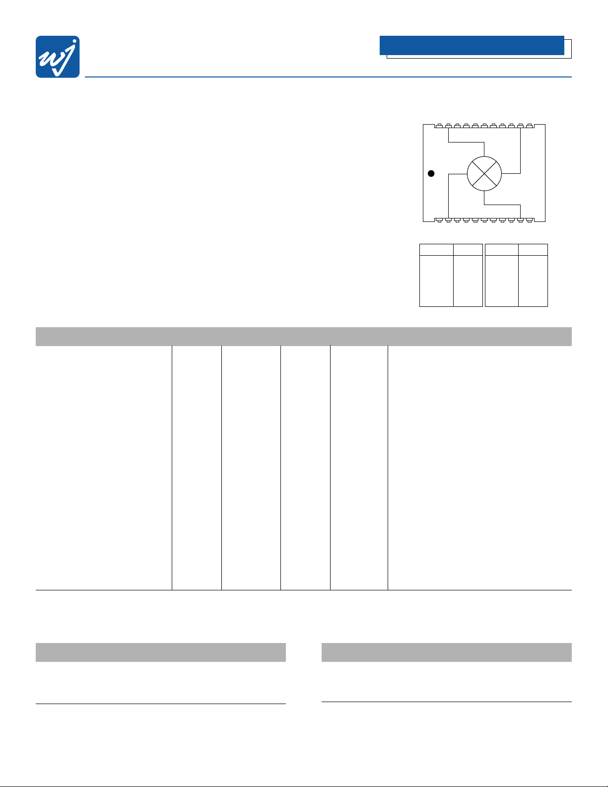
Functional Diagram
High Dynamic Range FET Mixer
Absolute Maximum Ratings
Parameter Rating
Operating Case Temperature -40 to +85°C
Storage Temperature -65 to +100°C
Maximum Input Power 25 dBm
1. Operation of this device above any of these parameters may cause permanent damage.
2.Total sum of LO port and RF port power should not exceed 25 dBm.
Ordering Information
Part No. Description
HMJ7 High Dynamic Range FET Mixer
(Available in tape and reel)
HMJ7-PCB Fully Assembled Application Circuit
Specifications
Parameter Units Minimum Typical Maximum Condition
Frequency Range:
RF MHz 1000 2000
LO MHz 1000 2000
IF MHz 10 1000
SSB Conversion Loss dB 8.5 9.5
Noise Figure dB 10.5
Isolation:
LO-RF dB 21 24
LO-IF dB 24 30
RF-IF dB 24
IIP3 dBm 30 34 RF = 1018 MHz (0dBm)
Return Loss:
RF Port dB 10
LO Port dB 5
IF Port dB 14
Spurious Rejection dBc 60
Input P1dB dBm 23
LO Drive Level dBm 21
DC Current at +5V Bias mA 40 60
Test conditions unless otherwise stated: RF = 1018 MHz (-10 dBm), LO = 1017 MHz (21 dBm), IF = 50-860 MHz and 25˚C.
The Communications Edge
™
2221201918171615 1413 12
1234567891011
Function Pin No.
Ground 1
IF 2
Ground 3-9
+5V DC 10
Ground 11
Function Pin No.
Ground 12
LO 13
Ground 14-20
RF 21
Ground 22
WJ Communications, Inc. • Phone: 1-800-WJ1-4401 • FAX: 408-577-6621 • e-mail: sales@wj.com • Web site: www.wj.com
June 2002
HMJ7
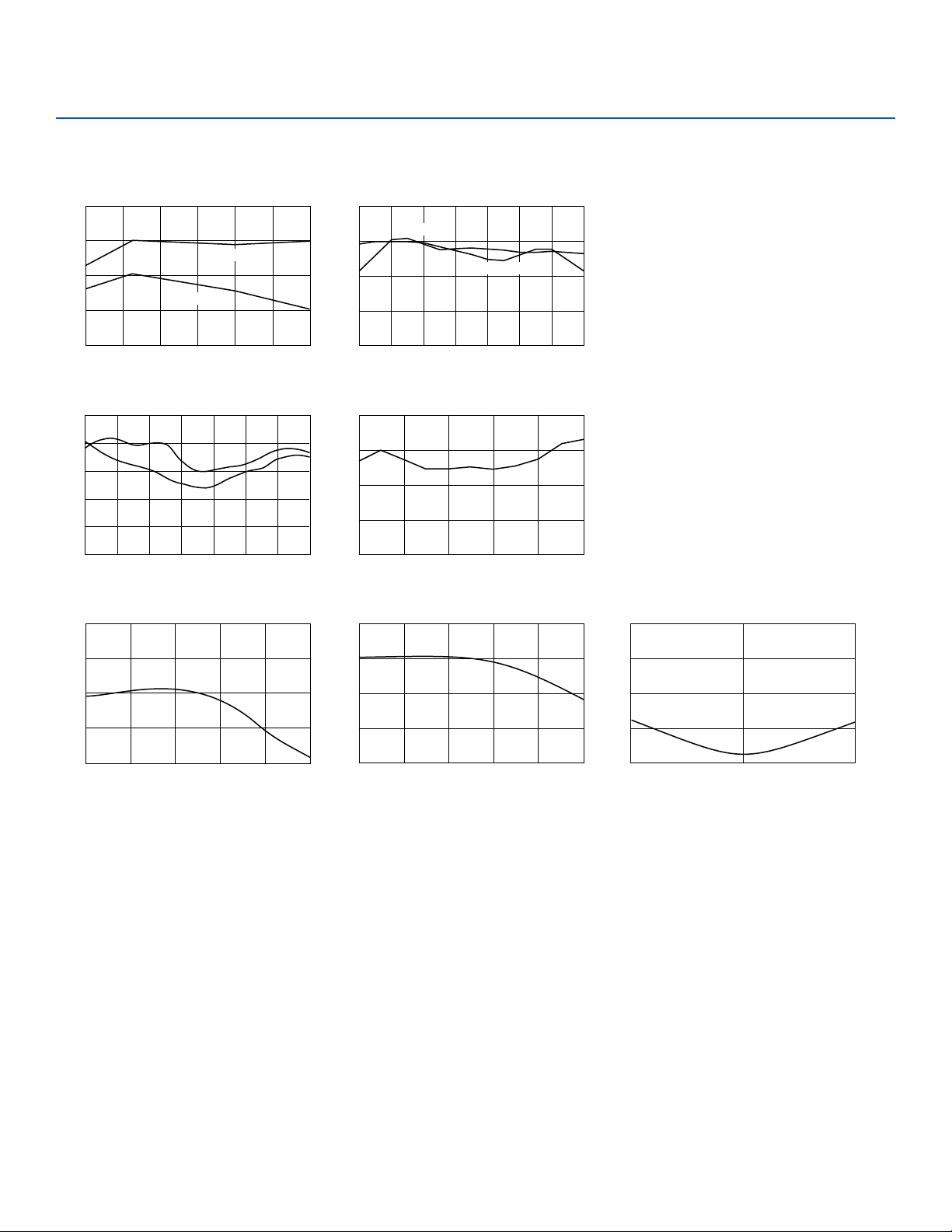
Conversion Loss vs. RF Frequency IIP3 vs. RF Frequency
RF Return Loss vs. RF Frequency
IF Return Loss vs. IF Frequency
LO Return Loss vs. LO Frequency
Isolation vs. LO Frequency
RF Frequency (MHz)
1100 1250 1400 1550 20001700 1850
45
40
35
30
25
IF = 10 MHz
IF = 500 MHz
Input Intercept Point (dBm)
Conversion Loss (dB)
RF Frequency (MHz)
800 1000 1200 1400 1600 1800 2000 2200
5
7.5
10
12.5
15
IF = 10 MHz
IF = 500 MHz
LO Frequency (MHz)
800 1000 1200 1400 1600 1800 2000 2200
Isolation (dB)
50
40
30
20
10
0
L-I
L-R
R-I
RF Return Loss (dBm)
RF Frequency (MHz)
1000 20001800160014001200
0
20
10
15
5
LO Frequency (MHz)
LO Return Loss (dB)
1000 1200 1400 1600 1800 2000
0
20
15
10
5
Isolation vs. RF Frequency
RF Frequency (MHz)
Isolation (dB)
1000 1200 1400 1600 1800 2000
40
0
10
20
30
IF Frequency (MHz)
IF Return Loss (dB)
10 500 1000
0
20
15
10
5
Performance Charts
 Loading...