


WJ Communications, Inc. • Phone: 1-800-WJ1-4401 • FAX: 408-577-6620 • e-mail: sales@wj.com • Web site: www.wj.com
April 2002
AH22
Product Description
The AH22 is a high dynamic range amplifier targeting cable TV markets. A combination of gain
flatness, high linearity and bandwidth make it
ideal for CATV distribution, cable modem and
laser diode driver applications. The device is
designed for 75 Ω systems and packaged for
push-pull operation. A mature and reliable GaAs
MESFET technology is employed to maximize
linearity at low power dissipation. The package is
a thermally enhanced SOIC-8 and all devices are
100% RF tested.
Product Features
•
50-860 MHz Bandwidth
•
-61 dBc CTB, 110 Channels,
40 dBmV
•
-63 dBc CSO, 110 Channels,
40 dBmV
•
4.5 dB Noise Figure
•
11.3 dB Gain
•
23 dBm P1dB
•
Surface Mount
•
Thermally enhanced SOIC-8 pkg
•
Single +5 Volt Supply
Functional Diagram
Absolute Maximum Ratings
Parameter Rating
Operating Case -40 to +85°C
Storage Temperature -40 to +125°C
Junction Temperature +155°C
Thermal Resistance (θ
JC
) 28°C/W
Supply Voltage +6.0 V
Input RF Power (continuous) +13 dBm
Operation of this device above any of these parameters may cause permanent damage.
Ordering Information
Part No. Description
AH22 High Dynamic CATV Range Amplifier
(Available in tape and reel)
AH22-PCB Fully Assembled Application Circuit
50-860 MHZ
AH22DUAL-PCB Fully Assembled Application Circuit,
Dual AH22
High Dynamic Range CATV Amplifier
Specifications
Parameter Units Minimum Typical Maximum Condition
Frequency Range MHz 50-860
S21-Gain dB 11.3
50 MHz
S21-Gain dB 11.0
860 MHz
S11-Input Return Loss dB -12
S22-Output Return Loss dB -12
Output IP3 dBm 41
Output IP2 dBm 65
Noise Figure dB 4.5
Output P1dB dBm 23 71.7 dBmV
CSO dBc -63 110 channels, 50-750 MHz, 40 dBmV
output/channel
CSO dBc -58 135 channels, 50-860 MHz, 39 dBmV
output/channel
CTB dBc -61 110 channels, 50-750 MHz, 40 dBmV
output/channel
CTB dBc -59 135 channels, 50-860 MHz, 39 dBmV
output/channel
Operating Current Range mA 240 300 360 Vdd = 5.0 V
Supply Voltage V 5
Test conditions unless otherwise noted.T = 25˚C, Vdd = 5.0 V, 75 Ω system.
1.Typical specifications reflect AH22 measured with external matching circuits.
2. OIP3 measured with 2 tones at an output power of 8 dBm/tone separated by 10 MHz. The suppression on the largest IM3 product is used to calculate OIP3 using a 2:1 slope r ule.
The Communications Edge
™
8765
1234
Function Pin No.
Input 1 1
Ground 2,3,6,7
Input 2 4
Output/Bias2 5
Output/Bias1 8
WJ Communications, Inc. • Phone: 1-800-WJ1-4401 • FAX: 408-577-6620 • e-mail: sales@wj.com • Web site: www.wj.com
April 2002
AH22
Push-Pull Circuit: 50-860 MHz Performance Charts
Typical Performance (75 Ohm System)
Frequency 50 MHz 450 MHz 750 MHz 860 MHz
Magnitude S21 11.7 dB 11.7 dB 11.4 dB 11.3 dB
Magnitude S11 -11.0 dB -12.3 dB -11.7 dB -15.6 dB
Magnitude S22 -13.2 dB -11.9 dB -11.4 dB -12.3 dB
OIP2 72.0 dBm 70 dBm 72 dBm 70 dBm
OIP3 42.0 dBm 43 dBm 41 dBm 40 dBm
Bias Vds = 5 V, Id = 300 mA
Multi-channel Measurements
CSO -63 dBc 750 MHz 110 channels +40 dBmV/ch, Flat
CTB -61 dBc 750 MHz 110 channels +40 dBmV/ch, Flat
XMOD -61 dBc 750 MHz 110 channels +40 dBmV/ch, Flat
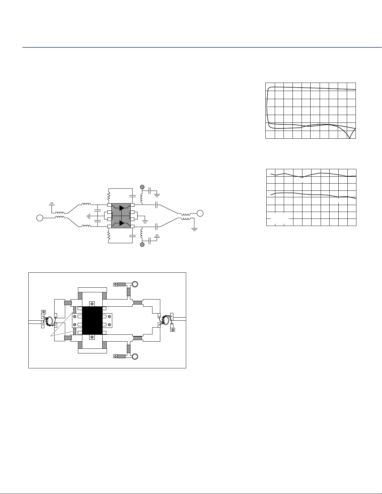
Schematic
DC +5 V
C = 1000 pF
R = 560
RF IN
6 turns bifilar
wire around
ferrite core
L = 5.6 nH
C = 1.5 pF
C = 1.5 pF
L = 5.6 nH
4 or more Via
Grounds req.
R = 560
C = 100 pF
AH22
C = 100 pF
DC +5 V
L = 470 nH
L = 470 nH
C = 1000 pF
Or
MaCOM
ETCI-1-13
SMT balun
6 turns bifilar
wire around
ferrite core
Core: TDK H5C2-T3.1-1.3-1.3
Wire: MWS B2383211
RF OUT
S-Parameters
15
10
5
0
-5
S11
Magnitude (dB)
-10
-15
S22
-20
0 100 200 300 400 500 600 700 800 900 1000
Frequency (MHz)
S21
Linearity vs. Frequency
80
70
60
50
40
30
20
Intercept Point (dBm)
V = 5 V
10
I = 290 mA
0
0 100 200 300 400 500 600 700 800 900 1000
OIP2
OIP3
Frequency (MHz)
FR4 Board Layout (T = 28 Mils to ground plane)
Interior Trans. Lines Z = 37.5 Ohm
1008 Package
L = 5.6 nH
0603 Package
R = 560 ohm
AH22
0402 Package
C = 1.5 pF
1008 Package
L = 5.6 nH
Note: Balun and board losses have not been extracted but typically account for 0.4 dB loss midband and 1.1 dB loss at 860 MHz.
0603 Package
R = 560 ohm
0603 Package
C = 1000 pF
0603 Package
C = 100 pF
0603 Package
C = 100 pF
0603 Package
C = 1000 pF
+5 V
L = 470 nH
Coilcraft
1008 Package
0603 Package
C = 1000 pF
0603 Package
C = 1000 pF
L = 470 nH
Coilcraft
1008 Package
+5 V

WJ Communications, Inc. • Phone: 1-800-WJ1-4401 • FAX: 408-577-6620 • e-mail: sales@wj.com • Web site: www.wj.com
April 2002
Dual Push-Pull Circuit: 50-860 MHz Performance Charts
Typical Performance (75 Ohm System)
Frequency 50 MHz 450 MHz 750 MHz 860 MHz
Magnitude S21 13.3 dB 13.3 dB 12.5 dB 12.3 dB
Magnitude S11 -21.0 dB -18.0 dB -21.0 dB -16.2 dB
Magnitude S22 -16.4 dB -18.2 dB -20.2 dB -17.1 dB
OIP2 73.0 dBm 72 dBm 75 dBm 76 dBm
OIP3 45.0 dBm 49 dBm 46 dBm 47 dBm
Bias Vds = 5 V, Id = 600 mA
Schematic
C = 1000 pF
L = 470 nH
C = 1000 pF
8 or more Via
Grounds req.
C = 1000 pF
L = 470 nH
C = 1000 pF
RF IN
6 turns bifilar
wire around
ferrite core
L = 3.3 nH
L = 3.3 nH
R = 560
R = 560
DC +5 V
C = 100 pF
C = 100 pF
DC +5 V
6 turns bifilar
wire around
ferrite core
or
MaCOM
ETCI-1-13
Surface Mount
balun
RF OUT
Core: TDK H5C2-T3.1-1.3-1.3
Wire: MWS B2383211
S-Parameters
15
10
5
0
-5
-10
Magnitude (dB)
-15
-20
-25
0 100 200 300 400 500 600 700 800 900 1000
S21
S22
S11
Frequency (MHz)
Linearity vs. Frequency
80
70
60
50
40
Intercept Point (dBm)
30
20
0 100 200 300 400 500 600 700 800 900 1000
OIP2
Frequency (MHz)
OIP3
V = 5 V
I = 600 mA
FR4 Board Layout (T = 28 Mils to ground plane)
Interior Trans. Lines Z = 37.5 Ohm
0603 Package
L = 3.3 nH
0603 Package
R = 560 ohm
AH22
AH22
0603 Package
L = 3.3 nH
Note: Balun and board losses have not been extracted but typically account for 0.4 dB loss midband and 1.1 dB loss at 860 MHz.
0603 Package
R = 560 ohm
0603 Package
C = 1000 pF
0603
Package
C = 100 pF
0603
Package
C = 100 pF
0603 Package
C = 1000 pF
+5 V
L = 470 nH
Coilcraft
1008 Package
0603 Package
C = 1000 pF
0603 Package
C = 1000 pF
L = 470 nH
Coilcraft
1008 Package
+5 V
GND

WJ Communications, Inc. • Phone: 1-800-WJ1-4401 • FAX: 408-577-6621 • e-mail: sales@wj.com • Web site: www.wj.com
April 2002
Outline Drawing
Land Pattern
Mounting Configuration

WJ Communications, Inc. • Phone: 1-800-WJ1-4401 • FAX: 408-577-6620 • e-mail: sales@wj.com • Web site: www.wj.com
April 2002
AH22
T ypical Test Data
S-Parameters, single unmatched device (Vdd = +5 V, Ids = 150 mA,T = 22°C, Z = 75 Ω)
Freq.(MHz) S11 (dB) S11 Ang S21 (dB) S21 Ang S12 Mag S12 Ang S22 (dB) S22 Ang
10 -12.892 -2.166 17.059 179.076 0.050 -0.502 -36.560 -65.063
50 -12.870 -11.286 17.067 176.030 0.051 0.301 -37.190 -72.212
100 -12.672 -23.045 17.043 172.073 0.051 0.703 -31.958 -82.160
150 -12.356 -33.366 16.967 168.036 0.051 0.964 -28.320 -90.551
200 -11.872 -42.817 16.894 164.326 0.051 1.258 -26.196 -94.845
250 -11.476 -52.297 16.801 160.805 0.051 1.800 -24.523 -100.971
300 -11.056 -60.214 16.723 157.092 0.052 1.771 -23.104 -103.565
350 -10.449 -67.937 16.619 153.456 0.053 1.858 -21.819 -105.985
400 -9.960 -74.745 16.514 149.951 0.053 2.304 -20.846 -108.359
450 -9.505 -80.896 16.376 146.241 0.054 1.529 -20.003 -110.824
500 -9.051 -86.735 16.220 142.910 0.055 1.348 -19.114 -114.155
550 -8.599 -92.061 16.067 139.571 0.056 1.105 -18.350 -115.873
600 -8.188 -97.267 15.918 136.143 0.057 0.884 -17.773 -119.083
650 -7.855 -101.536 15.725 132.858 0.057 -0.090 -17.233 -120.438
700 -7.497 -106.143 15.515 129.818 0.058 -0.565 -16.631 -122.901
750 -7.154 -110.057 15.370 126.785 0.058 -0.719 -16.162 -125.464
800 -6.889 -114.001 15.171 123.633 0.059 -1.741 -15.749 -127.412
850 -6.565 -117.238 14.956 120.846 0.059 -2.484 -15.276 -129.278
900 -6.298 -120.930 14.785 118.193 0.060 -3.030 -14.928 -131.457
950 -6.104 -124.039 14.586 115.177 0.060 -4.081 -14.636 -133.161
1000 -5.852 -127.205 14.378 112.740 0.061 -4.826 -14.283 -135.168
This document contains information on a new product.
Specifications and information are subject to change without notice.
Caution! ESD sensitive device.

WJ Communications, Inc. • Phone: 1-800-WJ1-4401 • FAX: 408-577-6620 • e-mail: sales@wj.com • Web site: www.wj.com
 Loading...