

WJ Company AH11PP900-PCB, AH11PP1900-PCB, AH11BAL-PCB, AH11 Datasheet
WJ Communications, Inc. • Phone: 1-800-WJ1-4401 • FAX: 408-577-6621 • e-mail: sales@wj.com • Web site: www.wj.com
February 2002
AH11
Product Description
The AH11 is a high power linear amplifier
for use in digital communications systems.
It combines low noise figure and high
intercept point into a low cost SMT
solution. This device extends the linear
efficiency advantages of WJ’s AH1 to higher
power levels. The device packaging allows for
both balanced and push-pull operation.
A mature and reliable GaAs MESFET
technology is employed to maximize
linearity at low power dissipation. The
package is a thermally enhanced SOIC-8
and all devices are 100% RF tested.
Product Features
•
250-3000 MHz Bandwidth
•
44 dBm Output IP3 in a Balanced
Configuration
•
47 dBm Output IP3 in a Push-
Pull Configuration
•
3.7 dB Noise Figure
•
12 dB Gain
•
27 dBm P1dB
•
Surface Mount
•
Thermally Enhanced SOIC-8 pkg
•
Single +5 Volt Supply
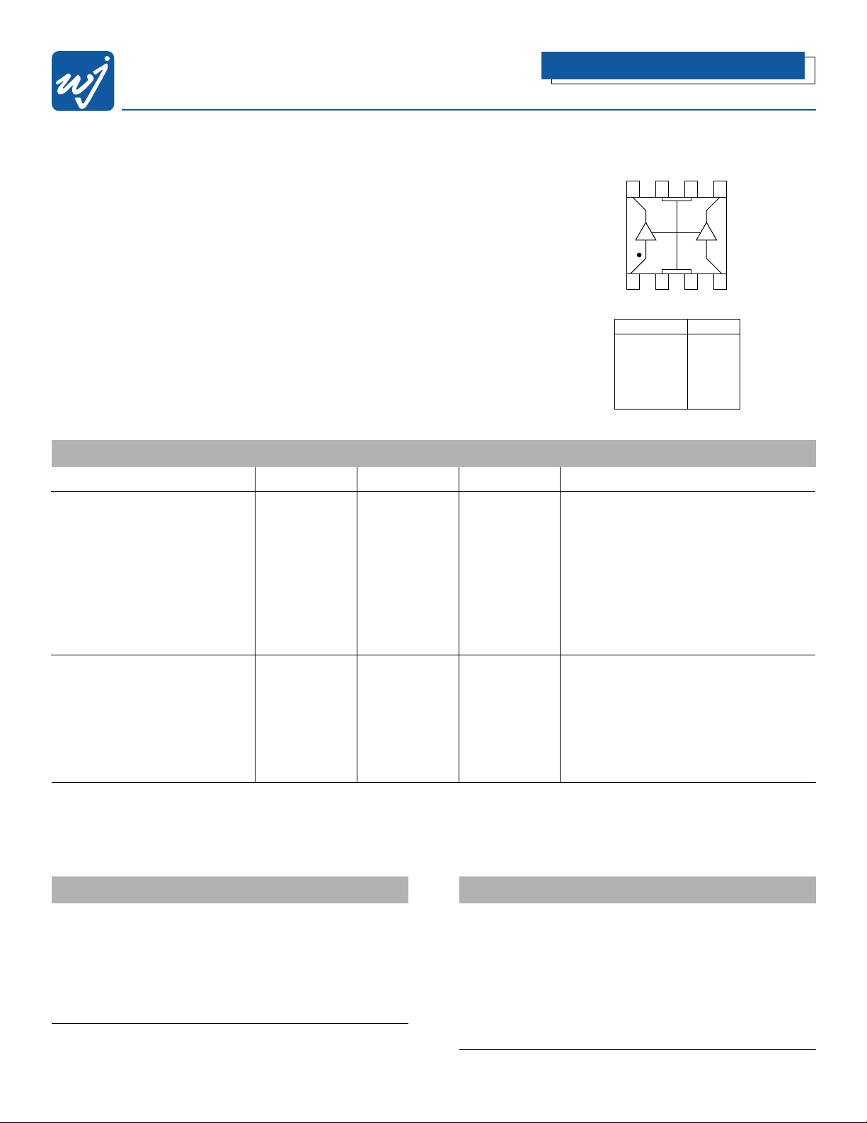
Functional Diagram
Absolute Maximum Ratings
Parameter Rating
Operating Case -40 to +85°C
Storage Temperature -40 to +125°C
Junction Temperature +155°C
Thermal Resistance (θ
JC
) 28°C/W
Supply Voltage +6.0 V
Input RF Power (continuous) +13 dBm
Operation of this device above any of these parameters may cause permanent damage.
Ordering Information
Part No. Description
AH11 High Dynamic Range Amplifier
(Available in tape and reel)
AH11BAL-PCB Fully Assembled Circuit Balanced
Configuration 600-2100 MHz
AH11PP900-PCB Fully Assembled Circuit Push-Pull
Configuration 900 MHz
AH11PP1900-PCB Fully Assembled Circuit Push-Pull
Configuration 1900 MHz
High Dynamic Range Amplifier
Specifications
Parameter Minimum Typical Maximum Condition
Supply Voltage (V) 5
Frequency Range (MHz) 600-2100 Frequency Range Limited by Ext Couplers
S21-Gain (dB) 11.0 12.2 900 MHz
S21-Gain (dB) 10.0 11.2 1900MHz
S11/S22 (dB) I/O Return Loss -15
Output IP3 (dBm) 44 46 900 MHz
(In a Balanced Configuration)
Output IP3 (dBm) 42 44 1900 MHz
Noise Figure (dB) 4.2
Output P1dB (dBm) 24
Operating Current Range (mA) 240 300 360
Frequency Range (MHz) 1700-2000 Frequency Range Limited by Ext Baluns
S21-Gain (dB) 12.0
S11/S22 (dB) I/O Return Loss -12
Output IP3 (dBm) 47
(In a 1900 MHz Push-Pull Configuration)
Noise Figure (dB) 3.7
Output P1dB (dBm) 27
Operating Current Range (mA) 480 600 720
Test conditions unless otherwise noted. T = 25˚C, Vdd = 5.0 V, 50 Ω system.
1.Typical specifications reflect AH11 measured with external matching circuits.
2. OIP3 measured with 2 tones at an output power of 8 dBm/tone balanced, 11 dBm/tone push-pull, separated by 10 MHz.
The suppression on the largest IM3 product is used to calculate OIP3 using a 2:1 slope rule.
3. Balun loss affects noise figure.
The Communications Edge
™
8765
1234
Function Pin No.
Input 1 1
Ground 2,3,6,7
Input 2 4
Output/Bias2 5
Output/Bias1 8
WJ Communications, Inc. • Phone: 1-800-WJ1-4401 • FAX: 408-577-6621 • e-mail: sales@wj.com • Web site: www.wj.com
February 2002
AH11
Typical Performance (50 Ohm System)
Frequency 600 MHz 900 MHz 1900 MHz 2100 MHz
Magnitude S21 10.7 dB 12.2 dB 11.2 dB 10.6 dB
Magnitude S11 -10.0 dB -10.0 dB -13.5 dB -10.0 dB
Magnitude S22 -12.7 dB -18.2 dB -10.0 dB -10.0 dB
NF 7.62 dB 4.13 dB 4.16 dB 5.55 dB
OIP2 63 dBm 65 dBm 65 dBm 63 dBm
OIP3 42 dBm 46 dBm 44 dBm 45 dBm
Bias Vds = 5.0 V, Id = 300 mA
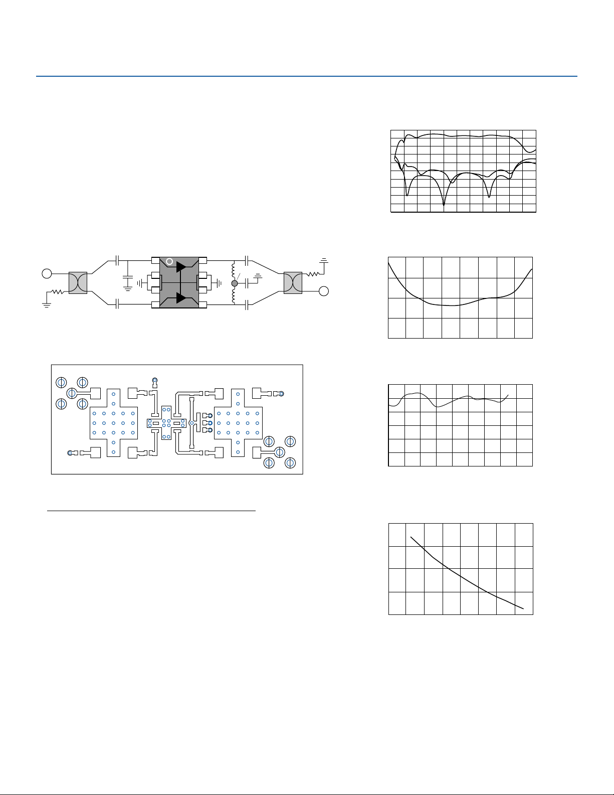
Schematic
RF OUT
DC +5 V
RF IN
C = 56 pF
C = 56 pF
C = 56 pF,
5000 pF
C = 56 pF
C = 56 pF
C = 2.0 pF
R = 50 ohm
R = 50 ohm
L = 12 nH
L = 12 nH
4 or more Via
Grounds req.
SMT 90 Coupler
Anaren 11305-3
SMT 90 Coupler
Anaren 11305-3
FR4 Board Layout (T = 14 Mils to ground plane)
AH11 Wide Band Balanced Amp
RF IN
RF OUT
Parts List
QTY Description Size MFR Part No.
1 Hi pwr Linear Amp SOIC8 WJ AH11
2 90 Coupler Wideband Anaren 11305-3
5 56 pF Capacitor 0603 Kemet
1 5000 pF Capacitor 0603 Kemet
1 .01uF Capacitor 0805 Kemet
2 12 nH Inductor 0603 Toko
1 2.0 pF Capacitor 0603 Kemet
4 100 ohm Resistor 0603
Balanced Circuit: 600-2100 MHz Performance Charts
20
10
0
-10
Magnitude (dB)
-20
-30
200 400 600 800 12001000 1400 1600 1800 20002200 2400
S21
S11
S22
Frequency (MHz)
NF vs. Frequency
S-Parameters
8
6
4
Noise Figure (dB)
2
0
600 800 1000 1200 1400 1600 1800 2000 2200
Frequency (MHz)
OIP3 vs. Frequency
50
45
40
35
OIP3 (dBm)
30
25
20
600 1000800 1200 1400 1600 1800 2000 2200 2400
Frequency (MHz)
MTTF vs. Temperature
11
10
9
10
7
10
MTTF (Hrs)
5
10
3
10
0 20 40 60 10080 120 140 160
Ground Tab Temperature (C)
 Loading...