

Page 1
1 Stationary RFID Portal Reader User’s Manual
1.1 Cover sheet
Copyright© 2005 by WJ Communications Inc. Subject to change without notice. This information is provided “as is,”
and WJ makes no claims of fit for purposes intended, merchantability or other. All trademarks, service marks, trade
names and logos are used in good faith and remain the property of their rightful owners.
page 1
Page 2

1 STATIONARY RFID PORTAL READER USER’S MANUAL.........................1
1.1 Cover sheet........................................................................................................................................ 1
1.2 Introduction ...................................................................................................................................... 3
1.2.1 Contents of this Document ......................................................................................................... 3
1.2.2 Audience..................................................................................................................................... 3
1.2.3 RFID System Quickstart............................................................................................................. 3
1.2.4 Product Description .................................................................................................................... 4
1.2.5 Unpacking and Inspection .......................................................................................................... 4
1.2.6 Product Installation..................................................................................................................... 4
1.3 Installation and Operation of demonstration Graphical User Interface ..................................... 5
1.3.1 Minimum System Requirements ................................................................................................ 5
1.3.2 Installation .................................................................................................................................. 5
1.3.3 Using the Demonstration software ............................................................................................. 8
1.3.4 COM Port Enumeration............................................................................................................15
1.3.5 Changing Software Parameters and Reader Configuration ...................................................... 18
1.4 RFID overview................................................................................................................................ 20
1.4.1 RFID operating principles ........................................................................................................ 20
1.4.2 RFID vs. bar code..................................................................................................................... 22
1.4.3 RFID system components......................................................................................................... 23
1.4.4 RFID standards......................................................................................................................... 29
1.5 Stationary portal RFID Reader Theory of Operation................................................................. 39
1.6 Host-Reader Interface.................................................................................................................... 41
1.7 Troubleshooting / technical support .............................................................................................41
1.8 Technical specifications.................................................................................................................. 41
1.9 Notices.............................................................................................................................................. 42
1.9.1 RFID limitations....................................................................................................................... 42
1.9.2 Safety........................................................................................................................................ 42
1.9.3 Limitation of liability................................................................................................................ 42
1.9.4 Patents....................................................................................................................................... 42
1.9.5 Copyright notice ....................................................................................................................... 42
1.9.6 Comments and feedback...........................................................................................................43
1.10 Regulatory Compliance.................................................................................................................. 43
1.10.1 FCC Statement.......................................................................................................................... 43
Copyright© 2005 by WJ Communications Inc. Subject to change without notice. This information is provided “as is,”
and WJ makes no claims of fit for purposes intended, merchantability or other. All trademarks, service marks, trade
names and logos are used in good faith and remain the property of their rightful owners.
page 2
Page 3
1.2 Introduction
1.2.1 Contents of this Document
This manual describes installation and operation of the WJ Communications UHF Stationary RFID Portal
Readers. A description of the installation and use of the demonstration Graphical User Interface is also
provided. The Application Programmer’s Interface to the Apollo-series devices using a serial
communications port is summarized; use of the Ethernet port to control the reader is described in a separate
document.
1.2.2 Audience
This manual assumes that the reader is generally familiar with Windows personal computers. An
introduction to RFID technology is provided for readers who are new to the field.
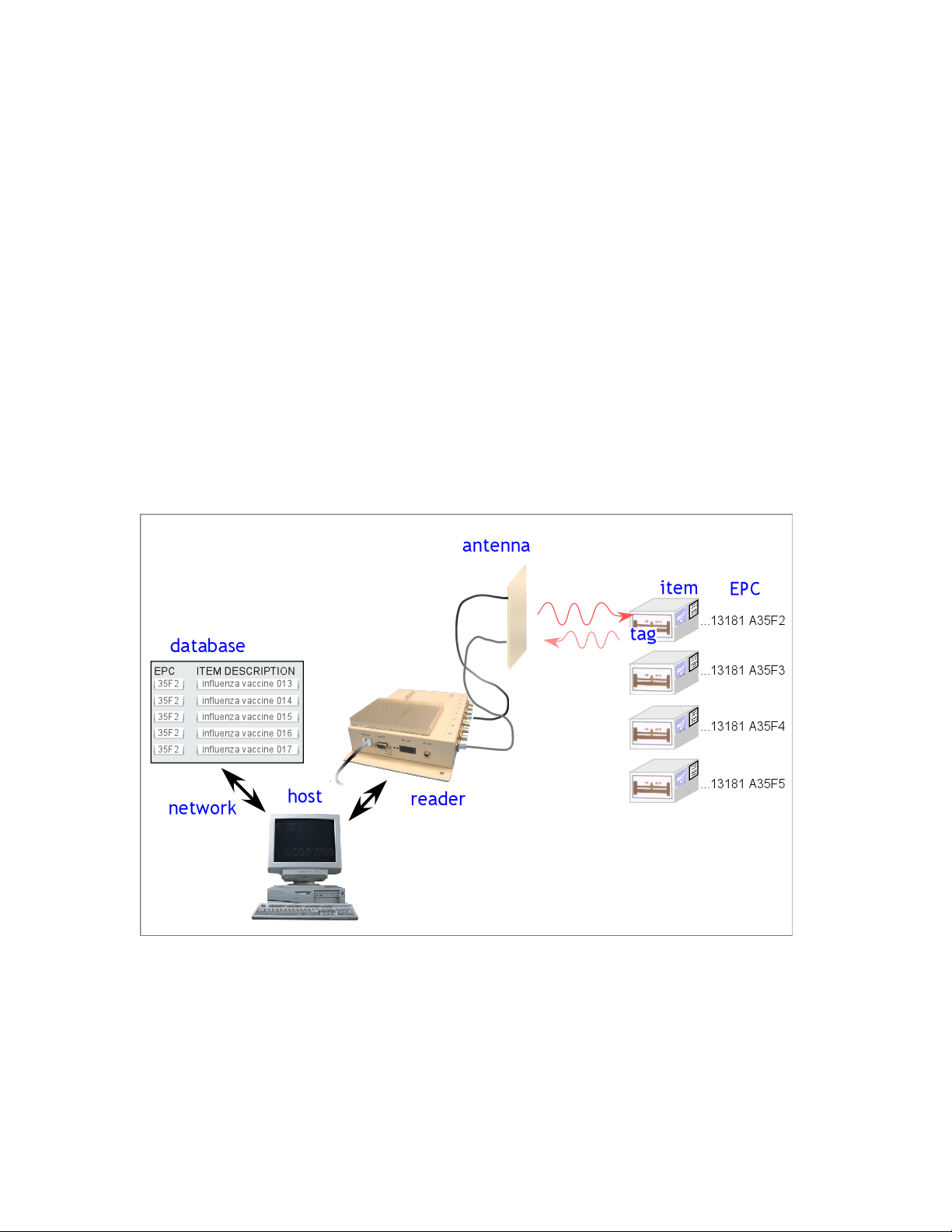
1.2.3 RFID System Quickstart
Radio Frequency Identification (RFID) uses electromagnetic waves to exchange information between a tag,
containing (at least) a number uniquely identifying that physical tag and by implication the object to which
it is attached, and a reader. RFID tags are analogous to bar codes, but can contain more information and
are more versatile.
The WJ Communications Stationary Portal Readers are UHF readers, operating at a frequency of roughly
902-928 MHz. These readers are compatible with EPCglobal Class 0 and EPCglobal Class 1 RFID tags,
as well as class 0+ tags and ISO 18000-B tags. They are not compatible with HF (13.56 MHz) tags
generally used in Smart Cards, or LF (125/134 KHz) tags generally used in animal identification. The
stationary portal readers are configured to use either an RS232 serial port or an Ethernet interface to
communicate with a host computer; direct optically-isolated I/O ports are also provided. With an
appropriate host and appropriate external antennas, a stationary portal reader can be used to acquire the
unique identification number (UID) of one or more compatible tags in its reading range. When multiple
tags are present in the field, collision resolution algorithms are applied to allow effectively simultaneous
reading of all the readable tags.
Copyright© 2005 by WJ Communications Inc. Subject to change without notice. This information is provided “as is,”
and WJ makes no claims of fit for purposes intended, merchantability or other. All trademarks, service marks, trade
names and logos are used in good faith and remain the property of their rightful owners.
page 3
Page 4
A more detailed discussion of RFID technology can be found in section 1.4.
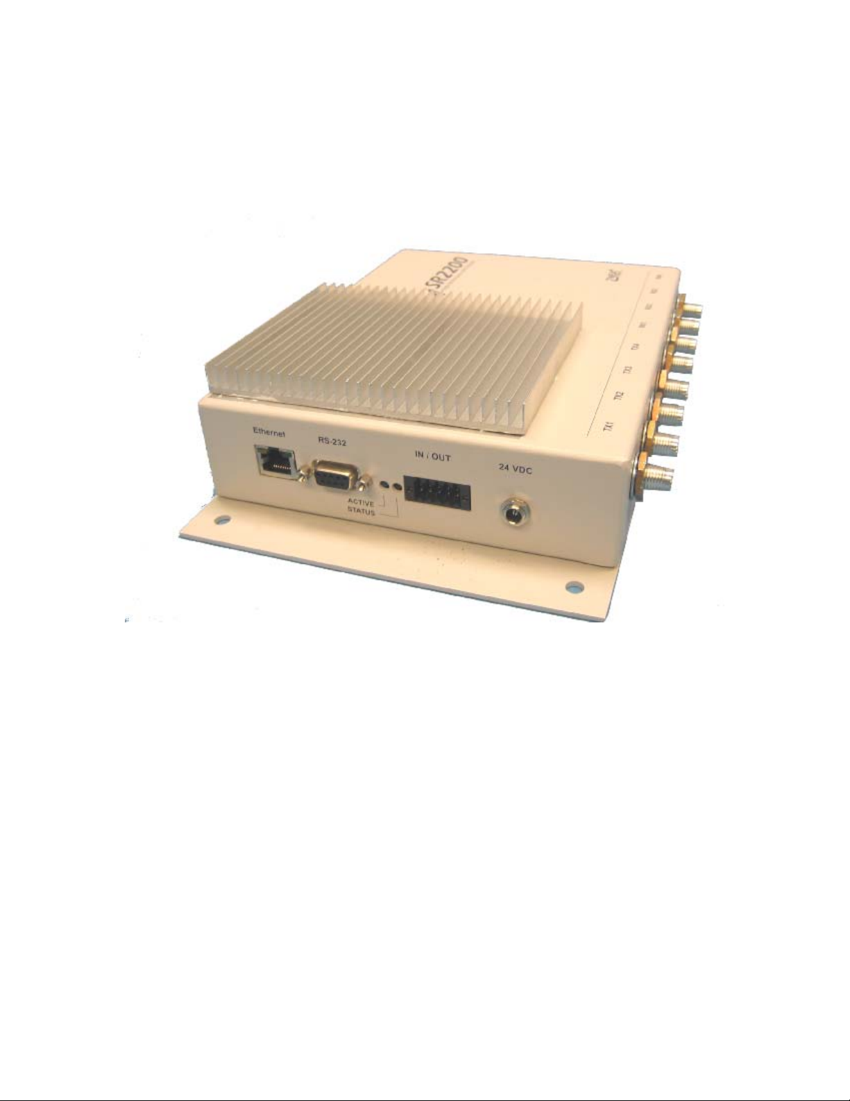
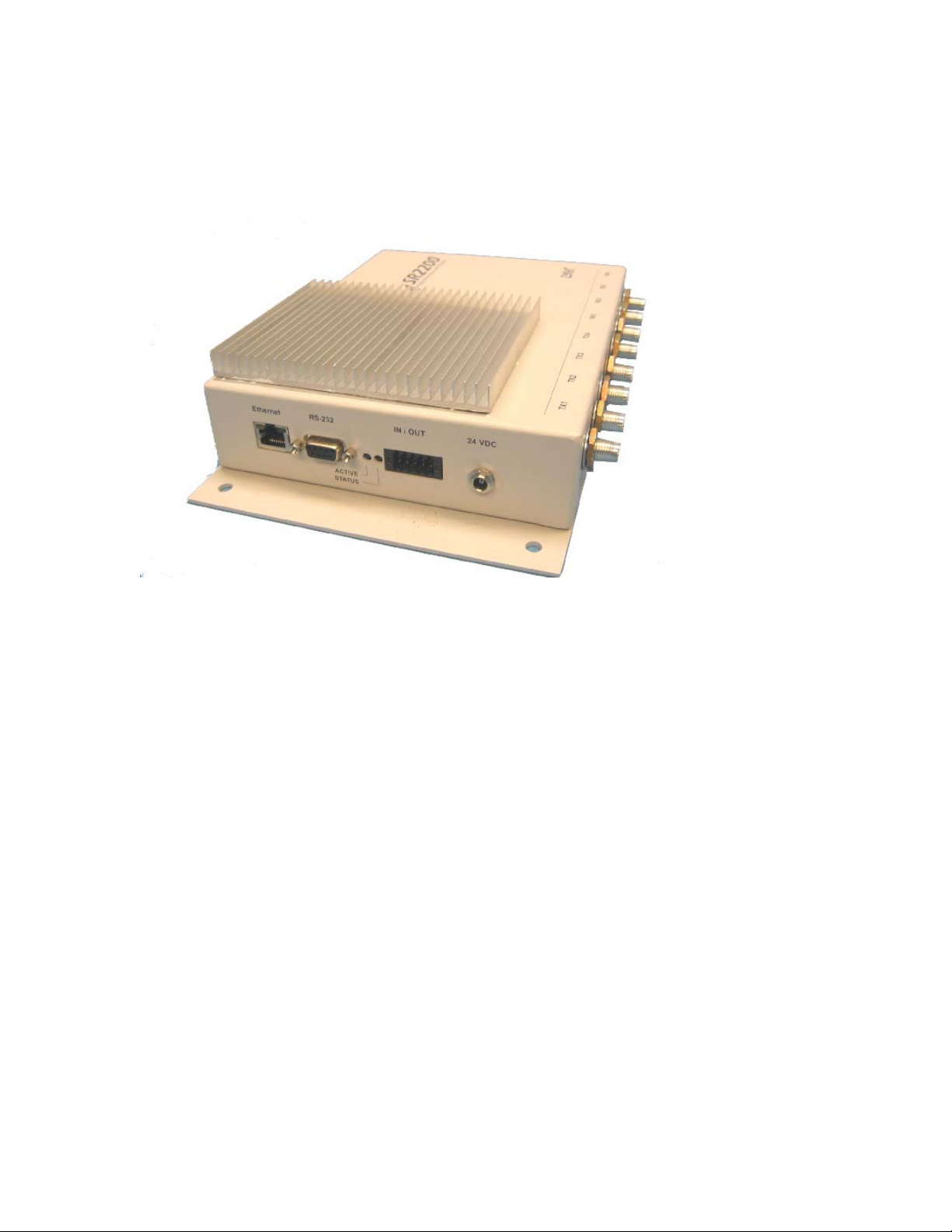
1.2.4 Product Description
The Stationary portal reader is a self-contained RFID reader configured for use at 902-928 MHz. Eight
antenna connections using mini-UHF connectors, normally configured as four pairs of (transmit – receive),
are provided on the back of the unit. Each pair can be connected to a WJ Communications model AN-120
antenna pair, or to other approved antennas. Communications with a host controller is achieved through a
conventional RS232 serial port. Optically-isolated direct I/O, and an Ethernet interface using a
conventional RJ45 connector, are also available.
1.2.5 Unpacking and Inspection
Box Contents:
• SR2200 Stationary Portal Reader
• A CD containing this User’s Manual and Demonstration Software
• AC power adaptor
• RS232 Serial Cable
• USB-to-serial adaptor
• Ethernet cable
• 50 ohm mini-UHF terminators (6)
• I/O port terminator
• Mounting hardware
Contents may vary slightly depending on the model number and options purchased.
1.2.6 Product Installation
The Stationary portal reader should be installed in a location protected from physical impact. The reader
may support up to 4 transmit-receive antenna pairs. The antennas should not be located more than 5 meters
Copyright© 2005 by WJ Communications Inc. Subject to change without notice. This information is provided “as is,”
and WJ makes no claims of fit for purposes intended, merchantability or other. All trademarks, service marks, trade
names and logos are used in good faith and remain the property of their rightful owners.
page 4
Page 5

(15 feet) from the reader. The reader should be securely mounted using the four mounting holes provided,
preferably in a vertical orientation allowing air to flow along the length of the cooling fins. At least 12 cm
(5 inches) of clearance should be provided in all directions from the reader. The reader and antennas
should not be located close to a strong source of RF interference such as a cordless telephone or 900-MHz
wireless local area network (WLAN) basestation. The antennas should not have any conductive (metallic)
obstructions within 50 cm in the direction in which tag reading is to be performed.
A possible installation sequence is as follows:
1. Mount the reader to a secure, stable surface, with adequate clearance and air flow.
2. Attach the antenna cables to the relevant mini-UHF connectors at the reader, and N-type
connectors at the antenna. Terminate unused mini-UHF connectors with 50 ohm loads.
3. Connect the RS232 serial control cable to the reader and the host computer.
4. Connect the 24 VDC power supply cable to the reader.
5. If the I/O port is not used, it must be terminated using the I/O terminator provided.
6. Place one or more appropriate RFID tags in front of one of the antenna pairs, within 1-2 meters.
It is important to note that transmit and receive antennas must be connected in pairs to corresponding
connectors. Thus, if only one antenna pair is employed, the transmit antenna may be connected to any of
the transmit connectors (e.g. TX1), but the receiving antenna must then be connected to the corresponding
receive connection (RX1 in this case). Antenna ports not used should be terminated with the 50 ohm
terminations provided. If separate transmit and receive antennas are employed, it is important that they be
oriented so as to view the same illuminated area, and preferably be coplanar so as to minimize coupling
between the antennas.
At this point the reader should be ready for operation using the demonstration graphical interface software,
or other custom control software.
1.3 Installation and Operation of demonstration Graphical User
Interface
The following description assumes the host computer is operating under Microsoft Windows XP; slightly
different screens will be visible if another operating system is employed.
1.3.1 Minimum System Requirements
This software requires a host computer running Microsoft Windows 98, NT, 2000 or XP, with a Pentiumcompatible PC and at least 128MB RAM, 50 MB available hard disk space, and 800x600 resolution or
higher. The configuration described presumes that an RS232-capable serial port or emulated serial port is
available. If the host computer is not equipped with a serial port connection, a USB-to-serial converter can
be employed. The converter may require additional driver software, not provided here.
1.3.2 Installation
1. Double-click on the file ‘rfiddemo_2.3.3_setup.exe’ or run the file from the START menu ‘run’
selection.
2. The installer should display the startup-screen:
Copyright© 2005 by WJ Communications Inc. Subject to change without notice. This information is provided “as is,”
and WJ makes no claims of fit for purposes intended, merchantability or other. All trademarks, service marks, trade
names and logos are used in good faith and remain the property of their rightful owners.
page 5
Page 6
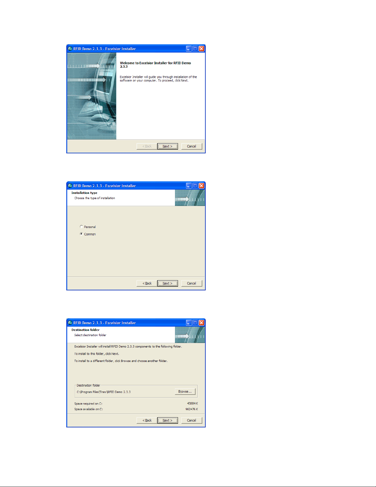
Click “NEXT”.
3. The installation-type screen gives you the option of installing the software so that it is available to
all users of the host computer (‘Common’), or only to the login name under which the installation
is performed (‘Personal’).
4. The installer asks where you would like to install the program. The default location is on the local
C disk in the Program folder. If you change the location of the program it is important to note
where it is installed, as you will need to access this folder to make modifications to the reader
configuration.
5. You are provided with the option of installing a demo icon in the Program folder, and a shortcut
on the desktop.
Copyright© 2005 by WJ Communications Inc. Subject to change without notice. This information is provided “as is,”
and WJ makes no claims of fit for purposes intended, merchantability or other. All trademarks, service marks, trade
names and logos are used in good faith and remain the property of their rightful owners.
page 6
Page 7
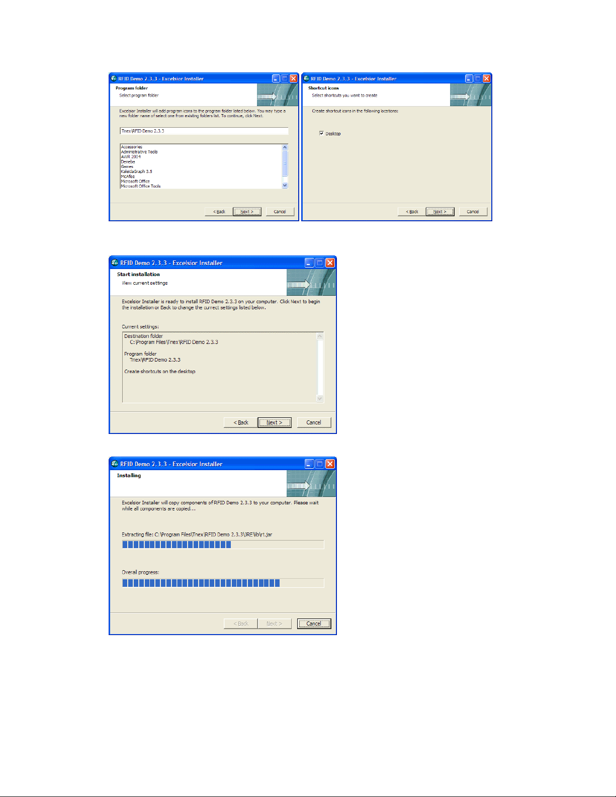
6. The installer then provides a summary of the selected parameters for you to review prior to actual
installation of the software. Click ‘Back’ if you decide to change any of the settings. Click ‘Next’
to begin the installation.
7. The installer copies the requisite files; progress is displayed in the installer window. This process
may take a few minutes.
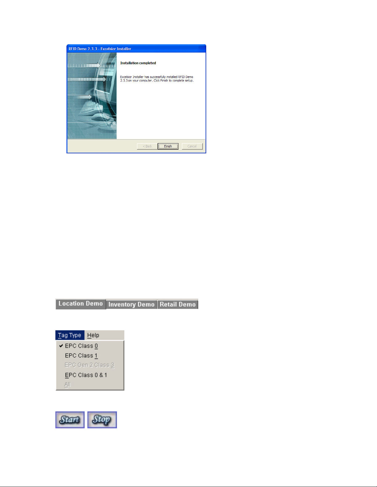
8. When the installer is finished the Installation Complete screen appears. Click ‘Finish’ to exit the
installer.
Copyright© 2005 by WJ Communications Inc. Subject to change without notice. This information is provided “as is,”
and WJ makes no claims of fit for purposes intended, merchantability or other. All trademarks, service marks, trade
names and logos are used in good faith and remain the property of their rightful owners.
page 7
Page 8
1.3.3 Using the Demonstration software
Introduction
The RFID Demo is an application for demonstrating the capabilities of the RFID hardware and Java API.
The demo consists of three individual demonstration modules: a Location Demo, an Inventory Demo, and
a Retail Demo. Each demo demonstrates different aspects and areas where the RFID hardware and API
can be applied. More details concerning each demo are described in later sections.
Running the Demos
Before starting the software, ensure that the reader is powered up and connected to one or more pairs of
antennas. Any antenna ports that are not used should be terminated by a 50-ohm load. The reader serial
port should be connected to the physical or emulated serial port on the host computer.
Start the demo software from the START menu or the desktop shortcut. Select the demo to run from the
tabs.
Select the tag type to read from the menu bar.
Press the 'Start' button to start the demo and begin reading tags. Press ‘Stop’ to stop tag reading.
Press the 'Clear' button to clear the data for the current demo. Press the 'Exit' button to exit the application.
Copyright© 2005 by WJ Communications Inc. Subject to change without notice. This information is provided “as is,”
and WJ makes no claims of fit for purposes intended, merchantability or other. All trademarks, service marks, trade
names and logos are used in good faith and remain the property of their rightful owners.
page 8
Page 9
Location Demo
The Location Demo is for demonstrating basic RFID functionality. It consists of four panels, which each
represent a location (typically configured as a pair of antennas; thus there are four possible locations
corresponding to the four antenna pairs supported by the unit). For this demo, one location directly
correlates to one antenna pair.
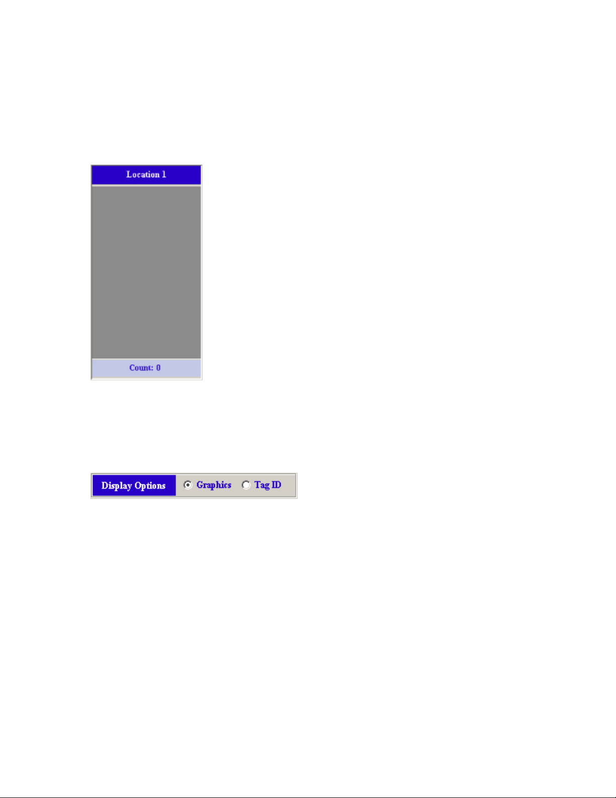
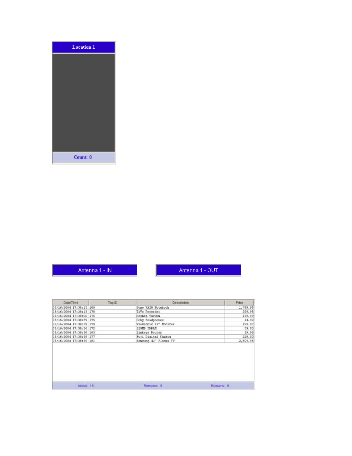
The top bar contains the location name (Location 1-4). It will show 'No Location' if that location is not set
for the selected reader. The bottom bar contains the count of tags being read.
The middle section displays the tags read either in graphic or text format, which can be selected from the
display options in the lower left corner of the application. The options are disabled if the demo is currently
running.
When the 'Graphics' option is selected, the panel will display one box for each tag read at that location. A
sample is shown below with three tags read.
Copyright© 2005 by WJ Communications Inc. Subject to change without notice. This information is provided “as is,”
and WJ makes no claims of fit for purposes intended, merchantability or other. All trademarks, service marks, trade
names and logos are used in good faith and remain the property of their rightful owners.
page 9
Page 10
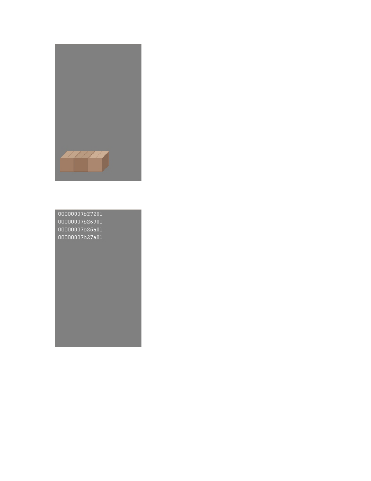
When the 'Tag ID' option is selected, the panel will display a list of all tag IDs that are being read. A
sample is shown below.
When the middle section is dark gray as shown below, there is no communication between the application
and antenna. Either an antenna fault or response error has occurred.
Copyright© 2005 by WJ Communications Inc. Subject to change without notice. This information is provided “as is,”
and WJ makes no claims of fit for purposes intended, merchantability or other. All trademarks, service marks, trade
names and logos are used in good faith and remain the property of their rightful owners.
page 10
Page 11
Inventory Demo
The Inventory Demo simulates an inventory supply of incoming and outcoming goods. It demonstrates the
pairing of antennas as two locations: IN & OUT. Tags read at an IN location are added to the inventory.
Tags read at an OUT location are removed from the inventory. The demo consists of three areas.
The top bar displays the four antennas and their respective location IN or OUT. The antenna background
will be blue if the antenna is responding. It will be black if the antenna is not responding. 'No Location' will
be displayed if that antenna is not set for the selected reader.
Next to the antenna name is the location type. When an antenna section is pressed, it will switch that
antenna from IN to OUT and vice versa as shown below.
>>
When a tag is read at an IN location, an item is added to the inventory table for that tag as shown below.
When a tag is read at an OUT location, the item corresponding to that tag is removed from the inventory
table as shown below.
Copyright© 2005 by WJ Communications Inc. Subject to change without notice. This information is provided “as is,”
and WJ makes no claims of fit for purposes intended, merchantability or other. All trademarks, service marks, trade
names and logos are used in good faith and remain the property of their rightful owners.
page 11
Page 12
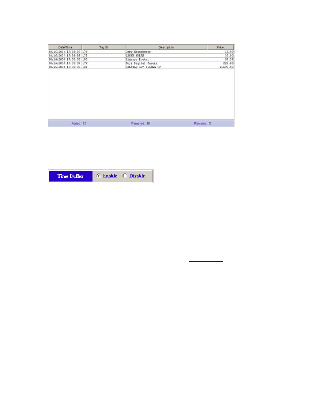
The bottom bar displays the inventory counters. It displays the overall count of items that have been added
to and removed from the inventory. It also displays the current count of items that still remain in inventory.
The time buffer filters consecutive tag events between IN and OUT locations. This is to demonstrate the
filtering of invalid reads between close proximity antennas.
When the time buffer is enabled, a tag read at an IN location will be ignored at an OUT location until a
span of 3 seconds has elapsed without being read again at the IN location. The time buffer is reset to 3
seconds every time the tag is read again at an IN location within the time window. Once the time buffer for
a tag has expired, the tag will not be ignored if read again at an OUT location. The same concept applies to
tags read first at an OUT location.
Retail Demo
The Retail Demo is very similar to the Inventory Demo
. It also simulates an inventory supply of incoming
and outgoing goods. The difference is that outgoing goods leave via the sales transaction checkout station.
The left section containing the table works almost exactly like the Inventory Demo
. Tags read at an IN
location are immediately added to the inventory. The difference is with tags read at an OUT location, which
is described below.
The right section or sales transaction section represents a retail checkout station. Tags read at an OUT
location are ignored until the 'Scan' button is pressed (shown below).
Copyright© 2005 by WJ Communications Inc. Subject to change without notice. This information is provided “as is,”
and WJ makes no claims of fit for purposes intended, merchantability or other. All trademarks, service marks, trade
names and logos are used in good faith and remain the property of their rightful owners.
page 12
Page 13
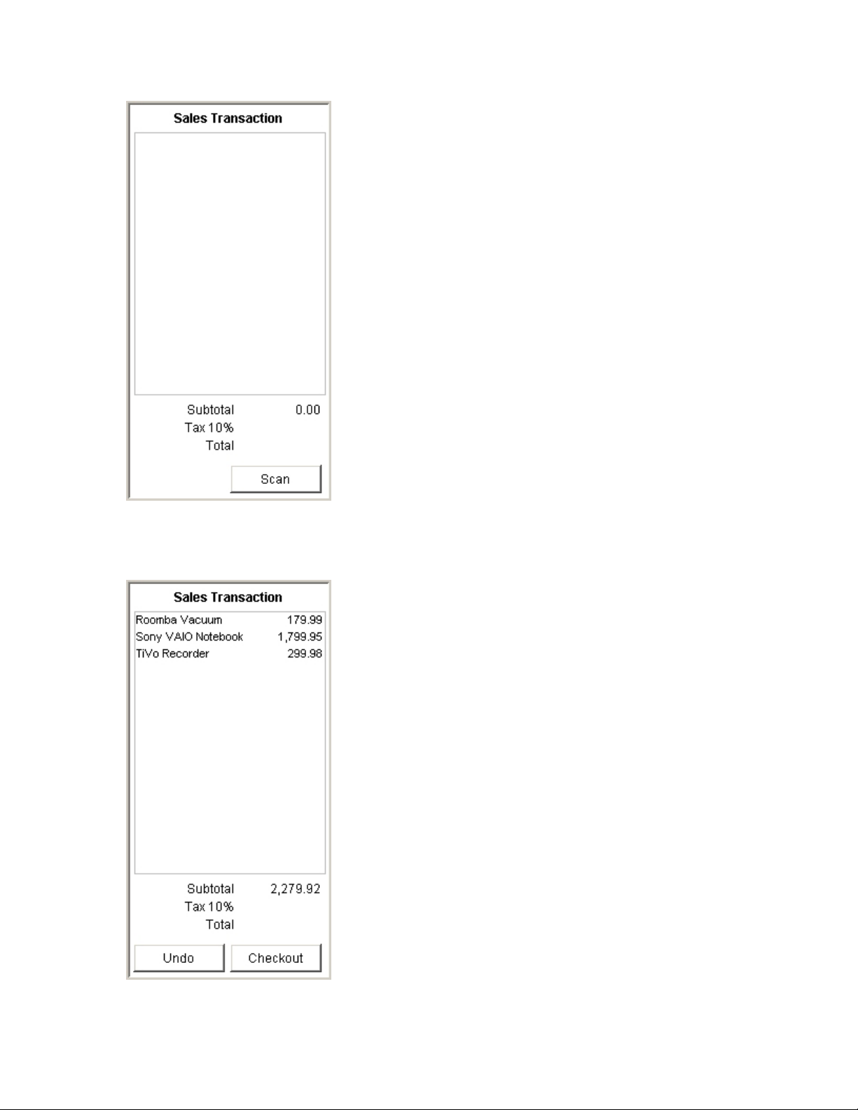
When the 'Scan' button is pressed, the sales transaction buttons will become 'Undo' and 'Checkout' as
shown below. Now when a tag is read at an 'Out' location, the item corresponding to that tag is removed
from the inventory and added to the sales transaction list also shown below.
Copyright© 2005 by WJ Communications Inc. Subject to change without notice. This information is provided “as is,”
and WJ makes no claims of fit for purposes intended, merchantability or other. All trademarks, service marks, trade
names and logos are used in good faith and remain the property of their rightful owners.
page 13
Page 14

The 'Undo' button will return all items in the sales transaction list back to the inventory table. Items can
also be returned from the transaction list back to the inventory by reading the corresponding tag at an IN
location.
The 'Checkout' button will complete the sales transaction. It will turn the sales transaction off and calculate
the tax and total of the transaction as shown below.
There is no time buffer for the Retail Demo.
Troubleshooting
Below are listed some common error conditions and means to correct them.
ERR001 - Communication Port Not Found
The serial port isn’t working, or has enumerated to a COM port different from what the software expects.
See sections 1.3.4 and 1.3.5 below for instructions on how to diagnose and correct these problems.
ERR002 - Communication Port in Use
Copyright© 2005 by WJ Communications Inc. Subject to change without notice. This information is provided “as is,”
and WJ makes no claims of fit for purposes intended, merchantability or other. All trademarks, service marks, trade
names and logos are used in good faith and remain the property of their rightful owners.
page 14
Page 15

The communication port is being use by another application.
- Close the application that is using the port.
ERR010 - Communication Response Error
There is no communication between the application and the reader.
- Restart the application.
- Check that the all connections are correct.
- Check that reader has power.
- Reset the reader by powering it off, waiting, and then powering it back on.
1.3.4 COM Port Enumeration
The default method for communication with the Stationary portal reader employs a serial port or emulated
serial port. In a Windows environment, serial ports are denoted by the word COM and a one-or-two-digit
number; thus the first port is COM1, the second COM2, and so on. The demo software assumes that the
reader is present on the COM1 port. If the host computer is equipped with a single physical serial port
(typically a D-sub-9 connector on the back of the unit, often labeled ‘COM’ or ‘COM1’), this port will
typically be COM1 and can be used to connect the host to the Stationary portal reader using a conventional
serial cable.
If a physical serial port is not available but a USB (universal serial bus) connection is, it is possible to
employ any one of a number of commercially-available converters that provide translation between the
USB and RS232 protocols. It may be necessary to install driver software in the host computer for the
converter employed. Once the converter is installed and running, it will appear to the host computer as a
serial port, but not necessarily as COM1. To find out which port the emulator has enumerated to, go to the
START menu and select Control Panel. In the Control Panel, select System.
Copyright© 2005 by WJ Communications Inc. Subject to change without notice. This information is provided “as is,”
and WJ makes no claims of fit for purposes intended, merchantability or other. All trademarks, service marks, trade
names and logos are used in good faith and remain the property of their rightful owners.
page 15
Page 16

In the System panel, click on the Hardware tab and select the Device Manager:
In the Device Manager, scroll down if necessary to find the list of ‘Ports (COM and LPT)’. You may need
to click on the [+] heading to see the list. The USB-to-serial device should be displayed, showing which
COM port it has been assigned to. In this case, a ‘Prolific USB-to-Serial’ converter has been assigned to
COM3. Your display may differ slightly depending on the brand of converter used.
Copyright© 2005 by WJ Communications Inc. Subject to change without notice. This information is provided “as is,”
and WJ makes no claims of fit for purposes intended, merchantability or other. All trademarks, service marks, trade
names and logos are used in good faith and remain the property of their rightful owners.
page 16
Page 17

If the port you wish to use to communicate with the reader is not assigned to COM1 you need to take one
of two approaches: you can reassign the port to COM1, or you can reconfigure the software to use the port
to which your reader cable has been assigned (COM3 here). Reassignment, described below, may not be
possible depending on the configuration of the host computer. Software configuration is described in
section 1.3.5.
To change the port assignment, double-click on the port (‘Prolific USB-to-Serial’ in the example shown) to
bring up the configuration screen for this port. Select the ‘Port Settings’ tab and click on ‘Advanced’.
Copyright© 2005 by WJ Communications Inc. Subject to change without notice. This information is provided “as is,”
and WJ makes no claims of fit for purposes intended, merchantability or other. All trademarks, service marks, trade
names and logos are used in good faith and remain the property of their rightful owners.
page 17
Page 18

In the resulting control window, select the pull-down menu for the COM port. If the COM port you want
(for example, COM1) is not in use you can reassign that number to the current port. However, if it is in use
you may need to reconfigure the demo software (section 1.3.5).
1.3.5 Changing Software Parameters and Reader Configuration
Changes to the COM port assignment, RF power level, delay between inventory operations, or other
parameters, you need to edit the text file RfidConfig.xml, located in the director \properties\ in the folder in
which the software was installed. If you did not change the default configuration, this folder will be found
in C:\Program Files\Tnex\RFID Demo 2.3.3. If you installed the software in a different location, you must
navigate to this location using Windows Explorer or the DOS window. The text file can be edited in any
environment that can edit and save pure text files. Typical word processors like Microsoft Word will not
save text files unless specifically instructed to do so. If you save to a pure text file from Word or another
standard word processor, ensure that the file name has not been changed, and in particular that the
extension remains ‘.xml’ and not, for example, ‘.txt’. It may be necessary to reconfigure Windows
Explorer to display filename extensions. The file consists of a series of XML statements; an excerpt is
shown below:
<?xml version="1.0"?>
<RIC>
<location class="com.tnex.services.common.location.LocationService">
<locationProp name="LocationName" type="String">a0</locationProp>
<locationProp name="ttl" type="Integer">2</locationProp>
</location>
<location class="com.tnex.services.common.location.LocationService">
<locationProp name="LocationName" type="String">b0</locationProp>
<locationProp name="ttl" type="Integer">2</locationProp>
</location>
…
COM Port Reassignment:
In the segment:
<protocol
class="com.tnex.services.common.protocols.sr2000.ProtocolService">
<protocolProp name="PortNumber" type="String">COM1</protocolProp>
<protocolProp name="TimeOut" type="Integer">3000</protocolProp>
<protocolProp name="BaudRate" type="Integer">57600</protocolProp>
<protocolProp name="DataBits" type="Integer">8</protocolProp>
<protocolProp name="StopBits" type="Integer">1</protocolProp>
<protocolProp name="Parity" type="String">NONE</protocolProp>
<protocolProp name="Delay" type="Integer">200</protocolProp>
<reader
class="com.tnex.services.common.datasources.rfreaders.sr2000.Sr2000Reade
rService">
change ‘>COM1<’ to whatever port your serial connection to the reader has been assigned to. In the
example of the previous section (1.3.4) the text would become:
<protocolProp name="PortNumber" type="String">COM3</protocolProp>
Save the file (make sure it has the same filename!) and restart the demonstration software.
RF Power:
Copyright© 2005 by WJ Communications Inc. Subject to change without notice. This information is provided “as is,”
and WJ makes no claims of fit for purposes intended, merchantability or other. All trademarks, service marks, trade
names and logos are used in good faith and remain the property of their rightful owners.
page 18
Page 19

In the segment
<antennaProp name="id" type="String">00</antennaProp>
<antennaProp name="power" type="Integer">255</antennaProp>
<antennaProp name="singulation" type="Byte">02</antennaProp>
change the value of “power” as appropriate. The power is entered as a decimal integer; the minimum value
is 0 (not very useful!), and the maximum value is 255. For example, to reset the power to a value of 200,
you can change the text to:
<antennaProp name="power" type="Integer">200</antennaProp>
Then save the file and restart the demonstration software.
An example relationship between the continuous-wave (CW) output power and the power setting for an
Stationary portal reader is shown below to provide rough guidance in the use of the power setting
parameter. Note that your reader may not produce exactly the same results as shown.
35
30
25
20
CW output power (dBm)
15
0 50 100 150 200 250 300
power setting
Delay between inventory commands:
To reset the inventory delay, edit the value of ‘Delay’ in the segment (the delay is given in milliseconds):
<protocol
class="com.tnex.services.common.protocols.sr2000.ProtocolService">
<protocolProp name="PortNumber" type="String">COM3</protocolProp>
<protocolProp name="TimeOut" type="Integer">3000</protocolProp>
<protocolProp name="BaudRate" type="Integer">57600</protocolProp>
<protocolProp name="DataBits" type="Integer">8</protocolProp>
<protocolProp name="StopBits" type="Integer">1</protocolProp>
<protocolProp name="Parity" type="String">NONE</protocolProp>
<protocolProp name="Delay" type="Integer">200</protocolProp>
For example, the following text would change the delay from 200 to 100 milliseconds:
Copyright© 2005 by WJ Communications Inc. Subject to change without notice. This information is provided “as is,”
and WJ makes no claims of fit for purposes intended, merchantability or other. All trademarks, service marks, trade
names and logos are used in good faith and remain the property of their rightful owners.
page 19
Page 20

<protocolProp name="Delay" type="Integer">100</protocolProp>
Note that the settings for the serial port can also be reset in this file. The default values are:
- Port Number: COM1
- Baud Rate : 57600
- Data Bits : 8
- Stop Bits : 1
- Parity : NONE
1.4 RFID overview
1.4.1 RFID operating principles
Radio-frequency identification (RFID) is an auto-identification technology, similar in concept to other
common auto-identification technologies such as bar code scanners, magnetic strip readers, or magnetic ink
readers. Like other auto-ID techniques. RFID associates an identifying number with a physical object. In
RFID, the unique identifying number (UID or, as will be explained below, EPC) is incorporated in a
special system, an RFID transponder (often simply known as a tag). An RFID Interrogator (usually
known as a reader) is used to obtain the UID from the tag using electromagnetic waves. The tag is usually
attached to a physical object that is to be identified, such as a carton, a pallet, or a container filled with a
product.
In order to reduce the cost of the tag, most tags do not incorporate a battery or other source of power, but
instead operate using DC power derived from the radio frequency signal they receive from the reader. In
addition, low-cost tags do not incorporate a radio transmitter, but instead use varying reflection of the
received signal from the reader to communicate back to it. Such tags are known as passive tags. Since
passive tags are the most common type, the description below will assume their use. Variants are also
available: semi-active tags incorporate a battery to power the integrated circuit, but still use reflected
Copyright© 2005 by WJ Communications Inc. Subject to change without notice. This information is provided “as is,”
and WJ makes no claims of fit for purposes intended, merchantability or other. All trademarks, service marks, trade
names and logos are used in good faith and remain the property of their rightful owners.
page 20
Page 21

waves (backscattering) to communicate with the reader. Active tags incorporate both a battery and a radio
transmitter, and are much more costly than passive tags, but also more versatile.
RFID systems can operate at different radio frequencies. The frequency chosen has important effects on
the way tags and readers interact and on what applications are appropriate.
Low-frequency (LF) tags and readers typically operate at 125 or 134 KHz. This is a very low frequency,
with a wavelength of about 2.4 kilometers (1.5 miles). Low-frequency radiation is very effective at
penetrating water and living tissues, so that LF tags can be used to identify livestock. However, because
the tags and readers are very much smaller than a wavelength, they cannot radiate effectively, so LF readers
and tags depend on inductive coupling to operate. In effect, the reader and tag form the primary and
secondary windings of a transformer. The tag must be in close proximity to the reader antenna to be read;
read ranges are comparable to the size of the reader antenna, typically a few 10’s of cm (5-10 inches) for a
small reader antenna. Because the induced voltage per coil winding is also very small at these frequencies,
the tags are composed of many turns of wire, often wound around a ferrite core to increase coupling. Since
there is no radiated power, there is usually very little issue with regulatory compliance in using LF tags and
readers.
High-frequency (HF) tags and readers operate at 13.56 MHz. This frequency is available for industrial use
in most jurisdictions worldwide. The wavelength is about 20 meters (60 feet), still larger than most reader
or tag antennas, so inductive coupling is used as in LF tags and readers. However, the higher frequency
provides a larger induced voltage, so the reader usually uses a single-turn coil, and transponders typically
incorporate 3-5 turns of wire. HF transponders can be readily constructed on a flat plastic substrate the
size of a credit card, forming Smart Cards widely used as identification badges and credit cards with
enhanced functionality. Typical read range varies from a few cm to a meter or so (a few inches to 3 feet),
again dependent on reader antenna size.
Copyright© 2005 by WJ Communications Inc. Subject to change without notice. This information is provided “as is,”
and WJ makes no claims of fit for purposes intended, merchantability or other. All trademarks, service marks, trade
names and logos are used in good faith and remain the property of their rightful owners.
page 21
Page 22

When long read range is required, ultra-high-frequency (UHF) tags and readers are appropriate. The
Apollo-series are UHF RFID readers. UHF systems typically operate at frequencies between 860 and 960
MHz, depending on the regulatory jurisdiction. In the United States, unlicensed operation is allowed in the
Industrial, Scientific, and Medical (ISM) band at 902-928 MHz. The wavelength at these frequencies is
about 33 cm (13 inches), so the reader and tags are roughly comparable in size to the wavelength. The
reader antenna creates a radiated electromagnetic wave, which can propagate long distances. UHF tags and
readers can thus exploit radiative coupling to achieve read ranges not available for LF or HF devices.
Read range for passive UHF tags can be as much as 10 meters (30 feet) with an appropriate directional
antenna; longer ranges are achievable using semi-passive tags.
RFID readers and tags operating in the microwave ISM band at 2.4-2.45 GHz are also widely used. The
2.4-2.45 GHz band is available for unlicensed operation in most jurisdictions worldwide. At this frequency
the wavelength is about 12 cm (5 inches). Very small tags can be used in the 2.45 GHz band, but because
of the consequent small antennas, the amount of power collected by a tag is reduced in comparison to UHF
tags. Passive 2.4 GHz tags have typical read ranges of around 1 to 3 meters (3 to 10 feet).
1.4.2 RFID vs. bar code
RFID tags and readers perform functions similar to those of bar codes and bar code scanners. How do they
differ? When should one use bar codes and when should RFID tags be employed? There are four key
distinctions to keep in mind:
• COST: bar codes can be printed on the surface of many existing packages at very low cost.
Separate bar-coded tags with adhesive backing are also inexpensive. Bar code scanners of various
types are widely available at modest cost, as is software to integrate bar code scanning into
standard business processes and enterprise planning. RFID (particularly at UHF and microwave
frequencies) is a relatively less widespread technology, and RFID tags are manufactured objects
containing an integrated circuit and antenna structure. RFID tags today cost significantly more
than bar codes, the exact value depending on type and quantity, though the cost of RFID tags is
falling rapidly as economies of scale are applied. Low-cost readers such as the MPR5000 are just
becoming available, but most readers are still expensive proprietary devices. When cost is the
only or a dominant issue, bar codes should be used.
• INFORMATION: Bar codes usually contain very limited information. Bar codes printed on
mass-produced packaging inevitably identify only the type of product and not the unique
individual package in hand. Bar codes containing unique identifying information such as serial
numbers can be used, but must be individually printed, raising cost, and separate codes are usually
needed to identify model number and the particular instance of the model. RFID tags generally
allow a 64-bit or 96-bit UID, the latter being more than adequate to identify manufacturer, model
or part number, and the specific physical instance of the model to which the tag is attached. More
advanced tags can contain additional user memory, which can be written to in the field, allowing
Copyright© 2005 by WJ Communications Inc. Subject to change without notice. This information is provided “as is,”
and WJ makes no claims of fit for purposes intended, merchantability or other. All trademarks, service marks, trade
names and logos are used in good faith and remain the property of their rightful owners.
page 22
Page 23

for versatile storage of information conveniently attached to an object when necessary. When
information storage capacity is a concern, RFID tags may be superior to bar codes.
• AUTOMATION: Bar codes require an optical line of sight between the reading device and the
code, and may also require that the code or reader be properly oriented. In many cases this means
that individual objects or tags must be handled by a human being in order to be reliable read.
UHF RFID tags can be read from a relatively long distance, and the path between the reader and
the tag can be visually obstructed (though certain obstructions will also affect radio frequency
devices, as will be discussed in more detail below). Bar codes are normally read one at a time,
particularly on randomly-oriented or stacked objects, whereas tens to hundreds of RFID tags can
be simultaneously present in the field of the reader and read ‘simultaneously’ from the viewpoint
of the user. RFID techniques permit automated information handling to a much greater extent
than bar codes.
• ROBUSTNESS: Bar codes cannot be read if the printed code becomes dirty, defaced, or
excessively bent or curled. RFID tags are robust to dirt, paint, ink, and to some extent mechanical
damage, and can be read (albeit with reduced range) when misoriented or mechanically distorted.
RFID tags are tougher than bar codes.
1.4.3 RFID system components
An RFID system is composed of (at least) a reader, one or more antennas, and one or more compatible
tags. In many applications it may be necessary or helpful to create human-readable labels incorporating
RFID tags; in this case an RFID tag printer is also very useful. While standalone RFID systems are
appropriate in some circumstances, more commonly the RFID reader is just a sensor that needs to interact
with a larger information system in order to be useful. Middleware is used to enable the interaction
between the reader and the network, and to filter and aggregate the large amounts of data the reader collects
into a more useful compendium provided to the network.
1.4.3.1 Reader
A UHF RFID reader is a radio transmitter and receiver. Most readers are capable of interrogating passive
tags, and are equipped with certain features uniquely suited to use for communicating with passive RFID
tags. A reader reading passive tags simultaneously communicates with the tag population and provides
power to operate the integrated circuits contained in the tags. During transmission, the reader transmits an
amplitude-modulated signal that is received by tags within range. The transmit power is generally limited
by regulatory requirements; for example, in the United States, no more than 1 watt average RF power may
be transmitted. Modulation rate varies depending on the standard employed, but is typically a few tens of
kilobits per second for UHF tags. Special coding of the transmitted data is employed to maximize the
power available to the tags.
Once the tags have been powered up and received their instructions from the reader, they take turns
responding with their UID. Because of the unique requirements of the backscatter radio system used by
passive and semi-passive tags, the reader must continue to transmit a non-modulated (continuous-wave or
CW) signal while it listens for tag responses. The tags employ the CW signal to continue to provide power
to the tag electronics, and modulate the impedance of their own antennas in order to vary the signal
reflected back to the reader. The reader must extract the very small tag reflections from all the other
reflected signals it encounters. The default configuration of the Stationary portal readers uses one antenna
to transmit, and a second (typically physically adjacent) antenna to receive the backscattered signal. Up to
four such pairs can be connected to the reader. The reader can switch from one antenna pair to the other in
order to cover differing physical regions, such as the high and low portions of a doorway, or to avoid
missing tags because of local losses of signal strength – fading – that are sensitive to the exact position of
the antenna and other objects. Any signal from the transmitting antenna that leaks into the receiving
antenna will compete with the small reflected signal from the tag; that is, it is desirable to have good
Copyright© 2005 by WJ Communications Inc. Subject to change without notice. This information is provided “as is,”
and WJ makes no claims of fit for purposes intended, merchantability or other. All trademarks, service marks, trade
names and logos are used in good faith and remain the property of their rightful owners.
page 23
Page 24

isolation between the transmit and receive antennas. Isolation will be degraded if conductive (metallic)
objects are placed close to the antennas. For best results, antennas should always be mounted in
accordance with manufacturer’s recommendations, and free of obstructions for at least 1 meter in the read
direction.
In the United States, readers are required by law to hop randomly from one frequency channel to another
when operating within the ISM band, residing for no longer than 0.4 seconds at any one frequency. In
addition, regulations forbid coordination of hopping patterns between collocated transmitters. When
configured for US operation, the Apollo series uses 50 channels separated from one another by 500 KHz,
and operates in each channel for 50 to 400 milliseconds. During hops from one channel to another, the RF
output is turned off.
1.4.3.2 Antennas
Antennas are the intermediaries between the voltages sent and received by the reader, and the
electromagnetic waves used to provide power to and communicate with the tags. Three critical
characteristics of antennas used in RFID systems are their maximum directive gain, polarization, and
match.
Electromagnetic radiation consists of a traveling electric and magnetic field. The electric field has a
direction at any point in space, normally perpendicular to the direction of propagation of the wave; this
direction is the polarization of the wave. For linearly polarized radiation, the direction of the electric field
is constant as the wave propagates in space. Configurations can also be constructed in which the direction
of the electric field rotates in the plane perpendicular to the direction of propagation as the wave
propagates: this is known as circular polarization.
The best power transfer between antennas is obtained when their polarizations match. Thus the best read
range is obtained from e.g. a vertically polarized reader antenna transmitting to a vertically polarized tag
antenna. This is an excellent scheme to employ when the orientation of the tag during reading can be
controlled. However, if the orientation of the tag can vary, the tag could accidentally be perpendicular to
the polarization of the reader antenna – a horizontal tag with a vertically polarized signal in shown in the
diagram below – in which case very little power is received, and the tag will not be read. When the tag
orientation is unknown or uncontrollable, a circularly polarized reader antenna should be used. Vertical
tags, horizontal tags, and tags rotated to intermediate angles can then be read with equal facility. However,
this versatility is not without cost. A circularly polarized signal can be regarded as the combination of a
horizontal and vertical signal, each containing half of the transmitted power. A linearly polarized tag
antenna only receives its own polarization, and thus half the transmitted power, being of the wrong
polarization, is wasted. The read range of a circularly polarized antenna with a linearly polarized tag is
Copyright© 2005 by WJ Communications Inc. Subject to change without notice. This information is provided “as is,”
and WJ makes no claims of fit for purposes intended, merchantability or other. All trademarks, service marks, trade
names and logos are used in good faith and remain the property of their rightful owners.
page 24
Page 25

reduced from what could be obtained with a linearly polarized reader antenna, if the tag orientation is
known.
In discussing antennas, it is often convenient to speak of an isotropic antenna that radiates power equally in
all directions, but no such antenna actually exists. Real antennas always transmit more effectively in some
directions than others. The ratio of the power density in the direction of highest power to the average
power radiated in all directions is the maximum directive gain, often simply referred to as the gain of the
antenna. It is important to note that antennas are passive devices and don’t actually add any power to the
signal provided by the reader: gain in this context refers to the increased power received by a device in the
best direction relative to the average of all directions. Gain varies tremendously for different antenna
designs. A very common antenna, the dipole antenna, is fairly close to an isotropic radiator: the dipole
sends no radiation along its axis, but transmits equally in all directions perpendicular to the axis and nearly
as well to directions at more than a few degrees away from the axis. The gain of a dipole antenna – the ratio
of the power density along the direction of maximum radiated power to the average of all directions – is
only about 1.7:1 or 2.3 dB
1
. Note that gain is often reported as ‘dBi’, the ‘i’ denoting the use of an ideal
isotropic antenna as the reference. A dipole antenna is a good choice when all tags in any direction along a
plane are to be read. Radiation from a dipole is polarized along the axis of the dipole; thus, a tag whose
antenna is also a dipole should be oriented in the same direction as the reader antenna in order to be read
effectively.
1
dB = deciBel is a method of logarithmically describing the ratio of two power levels; P21 (dB) = 10 log10
(P
). Thus 10 dB represents a factor of 10 in power.
2/P1
Copyright© 2005 by WJ Communications Inc. Subject to change without notice. This information is provided “as is,”
and WJ makes no claims of fit for purposes intended, merchantability or other. All trademarks, service marks, trade
names and logos are used in good faith and remain the property of their rightful owners.
page 25
Page 26

The recommended antenna antenna for the Stationary portal reader, WJCI model AN120, provides a pair of
circularly-polarized panel antennas in a single package, with excellent transmit-receive isolation and return
loss. This antenna provides about 6 dBi of gain on both transmit and receive.
In principle, antenna gain could be increased to increase read range. However, in most jurisdictions, the
maximum gain employed in unlicensed operation is limited by regulation. For example, in the United
States, the FCC limits the effective isotropic radiated power (EIRP, the product of the actual power and the
antenna gain) to 4 watts. The Stationary portal reader, which is rated at 1 Watt output, cannot use an
antenna with more than 6 dBi of gain.
Note that the recommended antennas have been specifically approved for use with the Stationary portal
reader in the United States by the FCC. FCC regulations (title 47 part 15) require that antennas be
approved for use with specific radio communications devices, unless they are installed by a professional
installer, and that in all cases the combination of antenna and radio device must operate within regulatory
constraints.
External antennas are generally connected to the reader using flexible coaxial cables and connectors. It is
important to select these cables and connectors appropriately for the application. The stationary portal
readers use mini-UHF connectors on the reader; the recommended AN120 antennas are equipped with
type-N connectors. Both are mechanically robust and convenient. When the antenna must be mounted a
long distance from the cable (more than 3 meters), a large-diameter low-loss cable, such as RG-213 or
RG214 should be used.
The electrical impedance presented by an antenna is a complex function of the frequency, the antenna
shape, and the near-antenna environment. Antennas are carefully designed so that the electrical impedance
of the antenna is well-matched to the impedance of the device to which they are connected. For example,
the Stationary portal readers will generally employ a cable with 50 ohm characteristic impedance to
connect the reader to the antenna. In order for the power from the reader to be effectively transferred to the
antenna, the antenna must have an electrical impedance close to 50 ohms, with little capacitance or
inductance, at the frequency of operation. As noted previously, conductive objects or some other materials
such as aqueous liquids placed close to an antenna will change its impedance and thus degrade its match to
the cable. For best read range, keep such obstructions away from the antenna in directions of maximum
directive gain.
Copyright© 2005 by WJ Communications Inc. Subject to change without notice. This information is provided “as is,”
and WJ makes no claims of fit for purposes intended, merchantability or other. All trademarks, service marks, trade
names and logos are used in good faith and remain the property of their rightful owners.
page 26
Page 27

1.4.3.3 Tags
A UHF RFID tag typically consists of a specialized integrated circuit (IC) attached to an antenna structure
fabricated on an inexpensive flexible plastic substrate. The antenna and substrate designs vary
considerably to meet the needs of specific applications. Tags may be configured to respond primarily to
one linear polarization, to have some response to both orthogonal directions, or to provide multiple
antennas with capability for switching the IC to the best direction at any given moment.
The natural size for an antenna structure for a given wavelength λ of electromagnetic radiation is about half
of the wavelength: λ/2. Since the wavelength is about 33 cm at 915 MHz, the natural size for a simple
antenna is about 16 cm (6.5 inches). Half-wave antennas radiate and receive effectively, and tend to have
convenient nearly-resistive impedances: they are resonant. However, for many applications such an
antenna is excessively large. Many tags are designed with antennas that are smaller than λ/2. While such
antennas may be configured to provide good impedance matching, some coMpromise in radiation
efficiency is inevitable: in general, smaller antennas will not perform as well as half-wavelength antennas.
Tag antennas may be bent or curved to conserve space and allow some response to multiple linear
polarizations; however, in this case only the regions of the antenna that are along the polarization direction
contribute to the received signal, so again the received power is reduced. Note that most tag antennas are
incorporated onto a flat plastic substrate and are thus themselves in a plane; like a dipole, the tag antenna
does not transmit and cannot receive signals whose direction of propagation lies in this plane. A tag cannot
be seen by the reader when it is viewed on edge.
Tag antennas are also sensitive to their local environment, a fact that is of particular import since tags are
meant to be attached to objects. Many common materials, such as paper and most plastics, have little effect
on microwave propagation; tags can be attached readily to cardboard or plastic boxes or containers without
affecting their operation. However, large metal objects have important effects both on the local electric
fields and the impedance of nearby antennas. Tag antennas cannot be attached directly to metal plates or
boxes without suffering degraded performance. Tag antennas spaced 5 mm to 1 cm (0.2 to 0.4 inch) from a
metal surface can perform acceptably, particularly if designed for near-metal service. Aqueous fluids
(water and water-containing materials such as milk, juices, most cleaning fluids, etc.) also have a strong
effect on local field intensity and may affect tag antenna impedance as well, depending somewhat on the
tag design. Again the best operation of a tag will be obtained if it is kept at least 1-2 cm from bodies of
aqueous fluid.
Copyright© 2005 by WJ Communications Inc. Subject to change without notice. This information is provided “as is,”
and WJ makes no claims of fit for purposes intended, merchantability or other. All trademarks, service marks, trade
names and logos are used in good faith and remain the property of their rightful owners.
page 27
Page 28

The received signal from a tag antenna is connected to an integrated circuit. Tag IC’s are very small (to
keep the cost of manufacturing low), and are typically embedded in a plastic coating for mechanical
protection. The IC contains a rectifying circuit to convert the received 900 MHz signal to a DC voltage
used to power the remainder of the IC. Variations in the received power are converted to variations in a
DC voltage, providing the IC with a method of sensing information transmitted by the reader. The IC can
also modify the impedance it presents to the antenna, by using a transistor as a switching element, thus
causing a variation in the signal reflected back to the reader and enabling the tag to communicate back to
the reader without needing its own radio transmitter.
The necessity of powering the tag is an important limitation on the read range. Tags require a few 10’s of
microwatts of RF power to operate, limiting the range to about 10 meters with the recommended antenna
pair. When linearly-polarized reader antennas are used, read range may be degraded by misorientation of
the tag. Most indoor environments have very complex propagation characteristics, with the transmitted
signal reflecting off numerous obstacles such as walls, floors, other tagged objects, people, vehicles, desks,
tables, etc. As a consequence, the signal strength can vary by a factor of 10 or more between two
neighboring locations separated by about a half-wavelength (16 cm or 5 inches): this phenomenon is known
as fading, and is encountered in most wireless communications systems. A tag with the misfortune to find
itself in a fade may fail to power up, while a tag farther from the reader but happily located in a region of
maximum signal strength responds readily. Thus there is no reliable simple correlation between tag
location the likelihood of reading a tag. The exact signal strength is sensitive to the positions of all
reflecting / diffracting objects in proximity to the read region (including people and their tools and toys) to
an accuracy of much less than a wavelength, and thus in practice is impossible to predict or control.
The best approach to deal with fading is the use of diversity: intentional variations in the propagation
environment to ensure that each tag finds itself in a region of decent signal strength at some point.
Diversity can be achieved by alternately employing two antennas in slightly different positions (displaced
by at least a half a wavelength); the Stationary portal readers can be operated in this fashion by the four
antenna pairs in succession. Alternatively, the location of the tags relative to the reader antenna(s) can be
varied; this beneficial effect occurs naturally when the tags to be read are moving on a conveyorized belt,
or are rotated as a pallet of boxes is wrapped with plastic in preparation for transport.
1.4.3.4 System integration
An RFID reader can collect large amounts of data, often much more than would have been obtained by a
human being employing a bar code reader. To convert this data into knowledge may require considerable
filtering. For example, if a fork lift driver moves a pallet out of a door, then returns to the facility to correct
an error in some paperwork, and finally drives out through the door to the truck again, the reader may take
three inventories of the same pallet, but it is rarely desirable to treat the resulting information as suggesting
that the same items were shipped three times. On the other hand, if the pallet is returned by a hand truck,
and the operator’s colleague stands in front of the reader antenna during the transfer, the reader may fail to
record some or all of the tags. A successful RFID implementation requires the integration of appropriate
procedures for human workers to follow in placing and using tags and objects carrying them, careful
installation of reader hardware, and the right middleware to convert the raw data from the reader into
information useful for operating the business.
Procedures are intimately connected with the planned usage for the RFID tags. Are the tags attached to
individual items, boxes, or a pallet or other large container? Are the items to be inventoried on a shelf,
counted as they move along a conveyorized transport belt, or tracked through a door? Can the orientation
of objects to be read be controlled or must the reader account for randomly-oriented tags, and does this
include tags placed end-on to the reader? What is the desired read range? Do the objects to be labeled
Copyright© 2005 by WJ Communications Inc. Subject to change without notice. This information is provided “as is,”
and WJ makes no claims of fit for purposes intended, merchantability or other. All trademarks, service marks, trade
names and logos are used in good faith and remain the property of their rightful owners.
page 28
Page 29

contain metals or aqueous fluids, and if so can the tags be placed sufficiently far from these disturbing
influences to be read? Is the necessary read reliability 90%, 99%, or 99.9%? Given the answers to such
questions, the implementer can then develop procedures to ensure that the desired reliability is achieved.
As might be inferred from the discussion in section 1.4.3.2, selection and placement of reader antennas is a
critical consideration for a successful installation. The stationary portal readers can be connected to up to
four external antenna pairs; these antennas should be configured to reliably cover the region over which
tags are to be read. For example, at a doorway, one directional antenna may be placed < 1 meter (3 feet)
from the ground and the other around 2 meters (6 feet) high, thus providing good coverage of the whole
door area. When many readers are used in close proximity, consideration should be given to minimizing
interference between readers; for example, configurations in which one reader antenna looks directly at a
neighboring reader’s antenna should be avoided. It may be useful to provide reflective or absorbtive
shielding between reader installations.
The lower levels of middleware, dealing directly with the reader population, must incorporate very specific
knowledge about the use procedures and environment in which the tags are being read, and are likely to be
highly customized for each application. This software must provide filtering and aggregation capabilities
to ensure that the data that is forwarded to the enterprise information systems is correctly categorized and
representative of what is happening to the physical inventory of objects being tracked. Once this has been
accomplished, the integration of a properly filtered and aggregated dataset with a standard enterprise
resource planning package such as those available from vendors like Oracle or SAP is a reasonably wellestablished function, with the necessary customization provided by a large number of third-party vendors.
1.4.4 RFID standards
Bar codes for commercial products are standardized worldwide under the auspices of the Uniform Code
Council and EAN International. In September of 2003, these organizations joined with the AutoID Labs
headquartered at the Massachusetts Institute of Technology to form EPC Global Inc., chartered with the
standardization of a generalization of the bar code system, the Electronic Product Code (EPC), as well as
the creation of software and hardware standards to support the use of RFID systems in implementing
identification of objects by means of EPC’s. This work is intended to complement existing and ongoing
activities at the International Standards Organization (ISO), where many standards for the operation of
LF and HF RFID systems have already been defined.
1.4.4.1 EPC Global
EPC Global is creating a set of standards intended to provide a robust infrastructure for the proliferation of
RFID technology:
• EPC Tag data: the standards define various formats for the unique identifier (EPC) for each tag, to
be consistent with existing EAN/UCC standards: serialized version of the EAN.UCC Global Trade
Item Number (GTIN®), the EAN.UCC Serial Shipping Container Code (SSCC®), the EAN.UCC
Global Location Number (GLN®), the EAN.UCC Global Returnable Asset Identifier (GRAI®),
the EAN.UCC Global Individual Asset Identifier (GIAI®), and a General Identifier (GID).
• UHF Tags: partial specifications for first-generation ‘class 0’ (factory-write-only) and ‘class 1’
(field-write allowed) tags are public. A second-generation standard for class 1 tags is in progress
at the time of this writing.
• Physical Markup Language: In order to provide a standardized framework for exchange of EPC
data between organizations, EPC Global is defining a physical markup language (PML) based on
the popular extended markup language (XML) widely employed in web communications. In
addition, standards for object name servers (ONS), analogous to the domain name servers
employed to facilitate communications over the Internet, are being defined. Finally, specifications
Copyright© 2005 by WJ Communications Inc. Subject to change without notice. This information is provided “as is,”
and WJ makes no claims of fit for purposes intended, merchantability or other. All trademarks, service marks, trade
names and logos are used in good faith and remain the property of their rightful owners.
page 29
Page 30

for the EPC Information Service (EPCIS) that will provide modular, standardized RFID
middleware functions are also being defined.
Tags compliant with the class 0 and class 1 EPC standards, manufactured by such vendors as Alien
Technology, Matrics (now a division of Symbol Technologies), and Impinj, are already in common
commercial use. Stationary portal readers will read both class 0 and class 1 and can write to class 0+ and
class 1 tags. Firmware upgrades will allow the stationary portal readers to read and write secondgeneration class 1 tags once they become available. Firmware upgrades will also support ISO1800-6B tags
(described below).
1.4.4.1.1 EPC Class 0 Summary
In this section we provide a very brief introduction to the operation of class 0 tags. Further information
may be obtained from the document “Draft protocol specification for a 900 MHz Class 0 Radio Frequency
Identification Tag”, dated 2/23/03, available from the EPC Global Inc. web site.
Class 0 tags are factory-programmed and thereafter read-only. Each tag contains a nominal 64-bit EPC and
a 16 bit cyclic redundancy check (CRC) in non-volatile memory. (Tags with 96-bit EPC’s are also
allowed, and are provided for in the Apollo-series firmware.) The CRC is independently re-calculated by
the reader when the EPC is read, and checked against that provided by the tag to check for errors in the
read.
When more than one tag is in the field of the reader, the reader employs a binary-tree traversal to resolve
possible collisions and individually address each tag (singulation). The traversal starts at the beginning of
an ID string and chooses one of the two possible branches (first bit = 0 or first bit = 1). All tags whose first
bit agrees with the reader’s choice remain in the traversal, while those with the opposite bit become
temporarily inactive waiting for the next traversal. When only one tag responds at any stage of the
traversal, that tag can be read. Proceeding in this fashion over the whole ID string (if necessary), the reader
must inevitably find all tags in the field if their ID’s are unique and all the tags are able to follow the
traversal.
In general, there are much less than 2
64
tags in the field in most practical cases. Thus it is often
unnecessary and wastefully slow to use the 64-bit EPC to aid in singulation. The protocol requires each tag
to provide two other ID’s in addition to the 64-bit EPC. These ID’s, known as ID0 and ID1, are both
pseudo-random 16-bit numbers. ID0 is generated by each tag upon request by the reader. ID1 is
programmed into each tag at the time of manufacture. In this nomenclature, the EPC is known as ID2.
During traversal, each tag still in the traversal backscatters the next bit of its active ID to the reader, and
listens for the reader to confirm that bit before remaining in the traversal. This procedure provides some
Copyright© 2005 by WJ Communications Inc. Subject to change without notice. This information is provided “as is,”
and WJ makes no claims of fit for purposes intended, merchantability or other. All trademarks, service marks, trade
names and logos are used in good faith and remain the property of their rightful owners.
page 30
Page 31

simple error checking. However, if the EPC (ID2) is being used for singulation, it has the consequence that
the reader sends some or all the bits of each tag’s EPC. Since it is much easier to intercept high-powered
reader transmissions than the low-power tag reflections, if security of tag EPC’s is a concern, ID2 should
not be used for singulation. Note that once a tag is singulated, the EPC can be read without echo by the
reader.
The protocol also allows for filtering, in which the inventory process is performed only on tags whose ID2
contains a fixed bit string provided by the reader. Filtering can be used to inventory only tags assigned to a
particular manufacturer or a particular product type.
Amplitude-modulation is used to transmit information from the reader to the tag. In order to maximize the
power simultaneously provided to the tag, special coding is employed to ensure that the reader power is
high most of the time. The particular scheme employed here is known as pulse-interval modulation. In
each symbol, a short low-power pulse (1/4 of the bit time) denotes a binary 0, and a longer low-power pulse
(half of the total bit time) denotes a binary 1. Thus the average transmitted power for a string with an equal
number of 1’s and 0’s is 5/8 of the CW power. A long low-power pulse (3/4 of the bit time) denotes a
special ‘NULL’ character, which appears infrequently and thus has little effect on the average power
delivered to the tag. In the United States, a data rate of 80 kilobits per second (Kbps) is used. In Europe,
a lower 16 Kbps rate is employed in order to operate within a narrower allowed channel.
Communication from the tag to the reader employs a sub-carrier modulation, in which the tag inverts states
at a rate much faster than the data rate. In the particular scheme used in this protocol, the tag sends a 2.25
MHz backscattered signal for a binary 0, and 3.25 MHz for a binary 1. Tag backscatter is performed on the
‘high’ portion of each reader bit. Sub-carrier signaling has two benefits: the reader need only detect
transitions of the tag state without regard to the direction of the transition (up or down), and if two or more
tags simultaneously backscatter binary 1 and binary 0, the presence of both symbols can be detected by the
reader, allowing it to gather some information about the tag population even when collisions are present.
Each time power is turned on, the reader proceeds through a set of steps to initialize the tag IC timing.
First, the reader transmits a RESET consisting of 800 µs of CW power. A tag’s “ID’d” flag (telling it that
it was already read by the reader) may survive a RESET, but in other respects the tag returns to its default
state. After the RESET, 8 pulses are used to calibrate the tag internal oscillator to the 2.2 MHz sub-carrier
frequency. Finally, a set of pulses of varying length is transmitted to set the thresholds for distinguishing
between 0, 1, and null, and to signal the tag when to begin its transmission.
Copyright© 2005 by WJ Communications Inc. Subject to change without notice. This information is provided “as is,”
and WJ makes no claims of fit for purposes intended, merchantability or other. All trademarks, service marks, trade
names and logos are used in good faith and remain the property of their rightful owners.
page 31
Page 32

In the United States, communications devices operating in unlicensed bands must either use directsequence or frequency-hopping spreading techniques. The Apollo series products use pseudo-random
hopping from one frequency to another. The Class 0 protocol does not require the reader to power down
during hops, but the Apollo series stationary reader does in order to minimize spurious radiation.
Therefore, a RESET / calibration sequence is necessary after each hop. The time between hops is available
for the user to adjust, although regulations require that the transmitter remain on any given frequency for no
longer than 400 ms at a time. In Europe, revised regulations allowing 10 channels have been promulgated
and it is anticipated that with the passing of time frequency-hopping operation will become the normal
means of operation in most European jurisdictions. European regulations will require that the reader listen
before talking: that is, the reader must check each putative channel for other active transmitters before
beginning its own transmission. Note that the MPR5000/6000/7000 operate at 902-928 MHz and are not
approved for use in Region 1 (European) jurisdictions.
Tags have 10 possible states, roughly corresponding to [startup / calibrate], [global commands], [binary tree
traversal], and [singulated commands]. Each command is 8 bits long, with an additional parity bit provided
for error checking. The tag echoes each bit it receives in order to provide a simple error check and
acknowledgement function. Mandatory commands are:
• ResetIDFlag: resets the identified flag to NOT READ; that is, it forces tags to forget whether they
have been previously inventoried.
• SetNegotiationPage: this curious terminology is used to describe the choice of ID (ID0, 1, or 2)
used for singulation during binary tree traversal.
• SegRegionofOperation: sets the backscatter parameters according to whether the device is
operating under FCC or European regulations.
• ForceDormant: tags receiving this command immediately enter the Dormant state. The Dormant
state is the default tag turn-on state, exited when a RESET is received.
• ForceMute: tags receiving this command immediately enter the Mute state. In the Mute state, the
tags receive data but do not respond until a NULL is received. Tags that have been bypassed
during traversal reside in the Mute state until the next traversal begins.
• Read: Read ID1 or ID2 (ID0, being randomly generated at the time of request, has no enduring
interest and need not be read from the tag).
• Kill: Permanently disables the tag if a valid argument (passcode) is provided.
1.4.4.1.2 EPC Class 1 Summary
In this section we provide a very brief introduction to the operation of class 1 tags. Further information
may be obtained from the document “Candidate Specification 860 MHz – 2500 MHz – Class 1 RFID Air
Interface”, revision 1.02, available from the EPC Global Inc. web site.
Class 1 tags are nominally factory-programmed but the write operation employs the radio interface and
could be performed at manufacture or in the field. It is expected that once the tag is written to, the memory
is locked and further write operations are disallowed. Each tag contains a nominal 64 bit or 96-bit EPC
and a 16 bit cyclic redundancy check (CRC) in non-volatile memory. The CRC is independently recalculated by the reader when the EPC is read, and checked against that provided by the tag to check for
errors in the read. Unlike class 0 tags, where the rag responds immediately to each bit sent by the reader,
class 1 tags use a more conventional packet-oriented protocol, with the reader transmitting a packet
containing commands and data, followed by a response by the tag.
When more than one tag is in the field of the reader, the reader employs a binary-tree traversal to resolve
possible collisions and individually address each tag (singulation). To begin the traversal, the reader sends
a filter string consisting of a pointer location and a bit stream. The pointer location indicates where the bit
stream starts in the EPC. Each tag tests the relevant portion of its EPC; those whose bits match the
transmitted bit stream then send the next 8 bits of their EPC back to the reader. Filtering is thus
Copyright© 2005 by WJ Communications Inc. Subject to change without notice. This information is provided “as is,”
and WJ makes no claims of fit for purposes intended, merchantability or other. All trademarks, service marks, trade
names and logos are used in good faith and remain the property of their rightful owners.
page 32
Page 33

incorporated in passing into the protocol. There are eight time slots for response, with the one chosen
dependent upon 3 of the reply bits. This time slot mechanism provides some collision resolution and a
simple error-checking mechanism. A simplified version of such a traversal is shown in the diagram below.
If the reader hears only 1 tag in a given bin, the reader can immediately request that tag’s full ID. Note that
with this mechanism, the reader may but need not transmit all or much of the tag’s EPC. Where security is
an issue, large sections of the EPC should not be used as filters.
Amplitude-modulation is used to transmit information from the reader to the tag. In order to maximize the
power simultaneously provided to the tag, special coding is employed to ensure that the reader power is
high most of the time. Class 1 tags use a pulse-interval modulation scheme quite similar to that employed
by class 0 tags. There are two options provided: a base set using a low pulse of 1/8 of a bit time for a
binary 0 and 3/8 for a binary 1, and an alternate set using times of ¼ and ½ of a bit time respectively (just
like the class 0 symbols). There is no NULL symbol. Thus the average transmitted power for a string with
an equal number of base-set 1’s and 0’s is ¾ of the CW power. In the United States, a data rate of about
62 kilobits per second (Kbps) is typically used. In Europe, a lower 15 Kbps rate is employed in order to
operate within a narrower allowed channel.
The return link uses a simple form of subcarrier modulation, F2F. Each bit time begins with a transition in
the tag state. To transmit a binary 0, the tag adds one transition in the middle of the bit. To transmit a
binary 1, 3 additional transitions are employed. (Thus, a string of binary 0’s has a fundamental frequency
of (1/Tbit), whereas the fundamental frequency of a string of binary 1’s is (2/Tbit), hence the name of this
coding scheme.) Each tag bit occupies ½ of the time used for a reader bit, so that the nominal data rates are
about 140 Kbps in the US and 30 Kbps in Europe.
Copyright© 2005 by WJ Communications Inc. Subject to change without notice. This information is provided “as is,”
and WJ makes no claims of fit for purposes intended, merchantability or other. All trademarks, service marks, trade
names and logos are used in good faith and remain the property of their rightful owners.
page 33
Page 34

Instead of employing a single long RESET and synchronization for a sequence of exchanges, as is done in
class 0, class 1 provides packet-by-packet tag synchronization. Each packets starts with a 64 µs CW period
to power up any tags in listening range, followed by data. During binary tree traversal, the reader then
sends a binary 1 to mark the edge of a response time slot or ‘bin’, so the tags have no need to maintain an
accurate clock to time the edges of the 8 possible response bins. A tag that response begins its packet with
a fixed 8-bit preamble, followed by the next few bits of its EPC, or in the case of a full scroll the remainder
of the EPC.
Tags have six possible states: Power Up, Awake, Asleep, Reply, Program , and Dead. Responses to
commands depend solely on the current state and not on how the tag arrived there. The basic commands
are:
• ScrollID: a tag whose EPC bits match the filter bits responds with its complete EPC
• Quiet: a tag whose EPC bits match the filter bits goes to sleep
• Kill: Permanently disable the tag if a valid argument (passcode) is provided.
• PingID: a tag whose EPC bits match the filter responds with the next 8 bits of its EPC
• Talk: a tag whose EPC bits match the filter bits wakes up
• ScrollallID: all tags hearing this command respond with their full EPC
• Pincscroll: Optional command allowing quick scroll of full ID from any tag that is the sole
responder in a given bin.
Copyright© 2005 by WJ Communications Inc. Subject to change without notice. This information is provided “as is,”
and WJ makes no claims of fit for purposes intended, merchantability or other. All trademarks, service marks, trade
names and logos are used in good faith and remain the property of their rightful owners.
page 34
Page 35

1.5.4.1.3: EPCGlobal Class1 Gen II Summary
EPCGlobal has ratified an iMproved ‘secondgeneration’ class 1, usually known as the Gen II
standard. The Gen II standard differs significantly
from the earlier class 0 and class 1 standards. Some of
the salient features are summarized here.
Gen II tags have a memory organized into banks.
Each bank is further subdivided into two-byte words.
Bank 00
passwords. Bank 01
corresponding error check (CRC), and protocol
control bits. Bank 10
about the tag itself. Bank 11
be organized in any convenient fashion.
Collision resolution in Gen II uses a different
approach from the binary-tree-based algorithms used
in class 0 and class 1 tags. Gen II uses a variation of
slotted Aloha, somewhat similar to the collisionresolution employed in Ethernet networks. If multiple
tags are present in the field, the reader can issue a
Query command with a parameter Q that describes the
size of the arbitration space. Tags randomly select an
arbitration value from 0 to 2
that value on each succeeding QueryRep command until the value reaches 0. Tags that have a zero-valued
counter reply to the Query. If the reader sees few responses, it can change the value of Q to make the
arbitration space smaller. If the reader sees many collisions, the value of Q can be increased to make more
room to arbitrate large numbers of tags.
is reserved for the access codes and kill
2
contains the unique EPC,
2
contains optional information
2
is user memory and may
2
Q
-1, and then decrement
Copyright© 2005 by WJ Communications Inc. Subject to change without notice. This information is provided “as is,”
and WJ makes no claims of fit for purposes intended, merchantability or other. All trademarks, service marks, trade
names and logos are used in good faith and remain the property of their rightful owners.
page 35
Page 36

Up to 4 simultaneous inventory sessions can be supported by each tag, using separate status flags for each
session. Because the singulation process makes use only of random numbers generated as needed to
support reader communications, the reader never transmits the EPC of the tag, reducing the likelihood of
interception of any sensitive information.
The reader and tag physical-layer symbols and modulation are
different from those used in class 0 or class 1. The reader
employs pulse-interval encoding. A binary ‘0’ is a high-low pair,
and the length of this symbol defines the important reference time
Tari. The binary ‘1’ consists of a high-period at least Tari long,
followed by a low power pulse of the same duration PW as the 0.
The binary ‘1’, as shown in the diagram, is at least 1.5 Tari long
but may be as long as 2 Tari.
The reader packet preamble for Query commands includes a time
reference signal, TRcal, that the tag uses in combination with a
divide ratio DR to determine the data rate it should use for its
reply.
Depending on what the reader requests,
the tag may reply using FM0
modulation (similar but not identical to
the F2F scheme used in the class 1
tags), or a Miller-modulated subcarrier
(MMS) symbol set, basically consisting
of FM0 symbols multiplied by a higherfrequency square wave. This system
supports a wide range of data rates from
around 20 Kbps to 640 Kbps, and
corresponding variations in tolerance to
noise and interference, at the cost of
some extra intelligence required from
the tag IC.
The Gen II standard also provides for three
different types of readers. Single
interrogators are readers that simply meet
local regulations for RF emissions, and are
substantially the same as currently-available
technology. Multiple-interrogator readers
are certified to meet a more demanding
spectral emission mask, in which reader
emission into adjacent frequency channels is
reduced by at least 20 dB, and into nextadjacent channels by at least 50 dB. Finally,
dense interrogator readers are required to
suppress adjacent-channel emission by at
least 30 dB, and next adjacent channel
emission by 60 dB, as shown in the diagram.
An active Gen II tag can be in one of 7 states.
The Ready state is entered when the tag
Copyright© 2005 by WJ Communications Inc. Subject to change without notice. This information is provided “as is,”
and WJ makes no claims of fit for purposes intended, merchantability or other. All trademarks, service marks, trade
names and logos are used in good faith and remain the property of their rightful owners.
page 36
Page 37

powers up. A Query command from the reader causes the tags whose flags match the Query to enter the
Arbitrate state, in which they create a slot counter value and decrement it on successive Queries until the
counter value reaches 0. When the counter is 0, the tags enter the Reply state and attempt to send a random
number to the reader. If the reader echoes that random number, the tag sends its unique EPC and enters the
Acknowledged state. Once a tag has been Acknowledged, the reader can send individual commands to that
tag in either an Open (non-secure) state, or using simple one-time-pad encryption in the Secured state.
Finally, a tag can be Killed; after acknowledging its demise, the tag should remain in the Killed state
permanently and no longer respond to any commands.
Reader commands are intentionally of differing bit lengths, in order to save link time and provide some
simple error checking. Some commands also use a packet error check (CRC) to detect bit errors.
1.4.4.2 ISO
The international standards organization has defined a number of standards covering RFID hardware and
operation. Currently, ISO is defining a series of tag and reader standards under ISO 18000, covering
operation at LF, HF, UHF, and microwave bands. ISO 18000-3 describes 13.56 MHz tags and readers,
generally assuming a thin, flexible form factor appropriate to smart cards or labels. ISO 18000-4 describes
operation at 2.45 GHz, including both passive and active versions. ISO 18000-6 describes two variant
forms (A and B) of UHF tags. Finally, ISO 18000-7 describes active tags operating at 433 MHz, providing
long range and high data rates but at much higher expense than passive tags.
ISO 15963 specifies unique tag identification numbers, and 15961 and 15962 specify data protocols and
encoding. ISO 18046 and 18047 specify test methods for tags and readers.
Copyright© 2005 by WJ Communications Inc. Subject to change without notice. This information is provided “as is,”
and WJ makes no claims of fit for purposes intended, merchantability or other. All trademarks, service marks, trade
names and logos are used in good faith and remain the property of their rightful owners.
page 37
Page 38

1.4.4.2.1 ISO 1800-6 Summary
ISO18000-6 describes two variants, type A and type B, using distinct forward-link modulations, collisionresolution approaches, and command sets, though both use FM0 modulation for the tag-to-reader link. The
Stationary portal reader supports ISO 18000-6B.
In the 18000-6B variant, Manchester-encoded symbols
are used by the reader, with amplitude-modulation depth
of either 100% or 11%. Binary ‘0’ and binary ‘1’
symbols have the same duration, but the opposite order:
a ‘1’ begins with RF power high, whereas a ‘0’ begins
with RF power low. There is no requirement for a
power transition at every symbol edge, so the tag must
be able to synchronize with the reader and sample at the
appropriate times to avoid misinterpreting transmitted
symbols.
The tags use FM0 (same as the basic Gen II modulation,
described in section 1.4.4.1.3 above) to communicate back to the readers.
The communications protocol is packet-based with a relatively complex reader packet.
The tag replies with a simpler packet after a wait time that depends on the current data rate.
Copyright© 2005 by WJ Communications Inc. Subject to change without notice. This information is provided “as is,”
and WJ makes no claims of fit for purposes intended, merchantability or other. All trademarks, service marks, trade
names and logos are used in good faith and remain the property of their rightful owners.
page 38
Page 39

Quiet CRC-16Data
Quiet
The tags maintain 8 flags, though only 4 are currently used. Two of the flags track initialized status and
write status; the other two are related to battery-powered tags. Tag memory is organized as up to 256
blocks of 1 byte each. The tag state diagram is relatively simple, with four basic states: power-off, ready,
ID, and data_exchange. Collision resolution employs another slotted-Aloha variant. Instead of changing
the size of the singulation space in response to collisions, the reader issues a failure notice, causing tags
with non-zero counter values to increment their counters. When a successful singulation occurs, the reader
issues a success notice causing tags to decrement their counters. Thus when collisions are frequent, tags
will count up and respond infrequently; when collisions are rare, tags will count down and respond.
There are mandatory commands for selecting or unselecting groups, initializing a tag population, and
sending SUCCESS or FAIL notices to the tags, and reading tags. Additional commands for WRITE and
LOCK functions are recommended but not required.
.
Return
Return
Preamble
Preamble
CRC-16Data
1.5 Stationary portal RFID Reader Theory of Operation
The Stationary portal RFID reader consists of a transmitter and receiver, both employing the same local
oscillator and direct up- and down-conversion from the carrier frequency, configured for operation within
the US Industrial Scientific and Medical (ISM) band at 902-928 MHz. The transmitter signal both provides
power to passive tags and delivers commands to the tags. The system is thus full-duplex in the sense that
the transmitter continues to operate during reception of tag signals, but half-duplex in terms of data
transmission, since when tag data is being received the transmitted signal is unmodulated CW. In a typical
exchange, the transmitter first powers up and sends a CW signal to provide power to tags in the read zone.
Then a baseband on-off-keyed modulation, appropriately filtered, is imposed on the CW signal with a
mixer. The reader data provides tags with synchronization information, requests tags to transmit their
unique IDs and other data in memory, and may write new data to a tag or erase its memory, etc. After a
command is given, the transmitter continues to transmit unmodulated CW power at the carrier frequency;
this CW signal both provides power to operate the tag’s integrated circuit, and provides the RF signal that
the tags backscatter to send their signals back to the reader. The details vary depending on the protocol
being used; see section 1.4.4 for a discussion of the differing protocols.
Copyright© 2005 by WJ Communications Inc. Subject to change without notice. This information is provided “as is,”
and WJ makes no claims of fit for purposes intended, merchantability or other. All trademarks, service marks, trade
names and logos are used in good faith and remain the property of their rightful owners.
page 39
Page 40

The backscattered signal is filtered and then mixed to baseband using the same VCO signal employed by
the transmitter; the Stationary portal reader is a homodyne radio. In-phase / quadrature (I/Q) demodulation
is employed in order to ensure that the baseband signal can be received despite variations in the absolute
phase of the reflected carrier. (Without this provision, depending on the exact separation of the tag and
reader antenna, the cable lengths, and other factors that cannot be controlled, the reflected signal would at
times be in quadrature with the signal from the VCO, so that the mixer would produce no baseband output.)
The outputs of the two mixers are filtered and amplified and then demodulated to extract the reflected
signal from the tags. After each command set the power shuts down while processing of the commands
proceeds. The nominal channel spacing is 500 KHz, providing 50 channels (with guard bands) within the
ISM band. In accordance with FCC regulations, the carrier frequency periodically ‘hops’ in a pseudorandom fashion over the ISM band to avoid persistent interference with other unlicensed users.
The overall system consists of the RF module, a controller, and interfaces to serial and Ethernet ports for
communication with a host computer or network.
Copyright© 2005 by WJ Communications Inc. Subject to change without notice. This information is provided “as is,”
and WJ makes no claims of fit for purposes intended, merchantability or other. All trademarks, service marks, trade
names and logos are used in good faith and remain the property of their rightful owners.
page 40
Page 41

1.6 Host-Reader Interface
If you want to create your own software to communicate with and control stationary portal readers, see the
document “SR2200 UHF Multi-Protocol RFID Reader RS-232 Serial Port Host Interface Protocol” for
control using the serial port.
1.7 Troubleshooting / technical support
1.8 Technical specifications
Parameter Specification
Operating Frequency US ISM band (902-928 MHz); frequency-hopping
Protocol support EPCGlobal Class 0, Class 0+, Class 1 Gen 1 and Gen 2
RF Transmit Power 1 Watt
Read Range 6 meters [20 feet] typical
Antenna ports Up to 4 pairs of (Transmit/Receive); mini-UHF connectors
Reader modes Host initiation mode or autonomous operation based on timer or external
trigger
Host interface Serial control over RS232, or TCP/IP over Ethernet; complies with
EPCGlobal draft Reader Host Specification
Operating temperature
Storage temperature
Power supply 24 VDC, 2.5 A
FCC certification FCC part 15 unlicensed operation [PENDING AT TIME OF WRITING]
0 to 50°C (32 to 122°F)
-20 to 70°C (-4 to 158°F)
Copyright© 2005 by WJ Communications Inc. Subject to change without notice. This information is provided “as is,”
and WJ makes no claims of fit for purposes intended, merchantability or other. All trademarks, service marks, trade
names and logos are used in good faith and remain the property of their rightful owners.
page 41
Page 42

1.9 Notices
1.9.1 RFID limitations
Communication between tags and readers at UHF frequencies is a complex phenomenon depending on
details of the environment surrounding the tags and reader(s) as well as the equipment being used. Some
environmental aspects (such as tag placement and orientation) may be controllable by the user; others (such
as reflections of the RF radiation by ambient objects) are generally not. Careful installation and testing,
and development and adherence to appropriate operating procedures, are indispensable for successful
implementation of RFID. WJ Communications Inc. makes no representation or warrantee that any specific
configuration of RFID tags and readers will provide any given performance characteristics.
1.9.2 Safety
Any use of this equipment with antennas or cabling installed outdoors or otherwise exposed to inclement
weather must avoid proximity with power lines or other high-voltage conductors, and provide for proper
grounding and lightning arresting devices to protect the equipment user in the event of a lightning strike.
See National Electrical Code (NEC) requirements articles 725, 800, and 810 for further information.
Do not operate the stationary portal readers in any area where critical safety equipment may be sensitive to
RF interference, such as medical or life support equipment.
Do not operate the stationary portal readers on board any aircraft in flight, or at any other time when
operation of radio devices such as cellular phones is prohibited.
Personnel should not be closer than 23 cm (9 inches) from any Stationary portal reader antenna for
prolonged periods of time. See FCC bulletins 56 and 65 for further information on electromagnetic field
exposure.
1.9.3 Limitation of liability
The information in this manual is subject to change without notice and does not represent a commitment on
the part of WJ Communications Inc. WJ Communications, Inc. specifically disclaims liability for any and
all direct, indirect, special, general, incidental, consequential, punitive or exemplary damages, including but
not limited to loss of profits, revenue, or anticipated loss of profits or revenue, arising out of the use or
inability to use any WJ Communications Inc. product, even if WJ Communications Inc. has been advised or
the possibility of such damages or they are foreseeable, or for claims by any third party.
1.9.4 Patents
Portions of the products described in this manual may be covered by granted or currently-pending US and
foreign patents.
1.9.5 Copyright notice
The contents of this document are the property of WJ Communications, Incorporated, except where
otherwise noted. Individuals who have purchased or otherwise legally acquired the stationary portal reader
hardware units described in this document are expressly permitted to make copies of the document, in
electronic or paper form, for personal, backup, and archival use. Brief segments may be excerpted and
used with attribution for descriptive purposes in commentaries, reviews, or other informational documents.
All other reproduction in whole or in part is expressly prohibited without the consent of the copyright
owner.
Copyright 2005 by WJ Communications, Inc.
Copyright© 2005 by WJ Communications Inc. Subject to change without notice. This information is provided “as is,”
and WJ makes no claims of fit for purposes intended, merchantability or other. All trademarks, service marks, trade
names and logos are used in good faith and remain the property of their rightful owners.
page 42
Page 43

1.9.6 Comments and feedback
Comments and feedback on this manual or the stationary portal readers are welcomed:
By phone: 1-800-WJ1-4401 (951-4401) or (972) 644-2328 x13
By email: RFID.info@wj.com
By physical mail: WJ Communications
TNEX Products Division
1909 N. Glenville Dr., Suite 200
Richardson, TX 75081
1.10 Regulatory Compliance
1.10.1 FCC Statement
This equipment has been tested [PENDING AT THE TIME OF THIS WRITING!] and found to
comply with the limits for a Class B digital device, pursuant to Part 15 of the FCC Rules. These
limits are designed to provide reasonable protection against harmful interference in a residential
installation. This equipment generates, uses and can radiate radio frequency energy and, if not
installed and used in accordance with the instructions, may cause harmful interference to radio
communications. However, there is no guarantee that interference will not occur in a particular
installation. If this equipment does cause harmful interference to radio or television reception,
which can be determined by turning the equipment off and on, the user is encouraged to try to
correct the interference by one or more of the following measures:
-- Reorient or relocate the receiving antenna.
-- Increase the separation between the equipment and receiver.
-- Connect the equipment into an outlet on a circuit different from that to which the receiver is
connected.
-- Consult the dealer or an experienced radio/TV technician for help.
NOTE: Changes or modifications not expressly approved by WJ Communications could void the
user's authority to operate the equipment described in this manual.
1.10.1.1 RF Radiation Exposure Statement
These devices comply with FCC radiation exposure limits set forth for an uncontrolled environment, and
users must follow specific operating instructions for satisfying RF exposure compliance.
Copyright© 2005 by WJ Communications Inc. Subject to change without notice. This information is provided “as is,”
and WJ makes no claims of fit for purposes intended, merchantability or other. All trademarks, service marks, trade
names and logos are used in good faith and remain the property of their rightful owners.
page 43
 Loading...