

WJ Communications SX1115 Hardware manual will be same for UNII but with MPE values shown in WJ test repor

Final Review - Cisco Internal Use Only
Text Part Number:
78-6030-01
Cisco uBR7200 Series Universal
Broadband Router Wireless Modem
Card and Subsystem Installation and
Configuration
Product Numbers: UBR-MCW-PDA, UBR-MCW-PDA=, UBR-WPFD, UBR-WPFD=,
CISCO-WT2772-PAA, CISCO-WT2772-PAA=, CISCO-WT2772-PBA,
CISCO-WT2772-PBA=, UBR-ODD-01A, UBR-ODD-01A=, UBR-ODD-02A,
UBR-ODD-02A=, UBR-ODD-03A, UBR-ODD-03A=, UBR-ODD-04A, UBR-ODD-04A=,
UBR-ODD-05A, UBR-ODD-05A=, UBR-ODD-06A, UBR-ODD-06A=,
This document explains howtoinstallandconfigurethecomponentsforahigh-speedpoint-to-point
fixed broadband wireless system using Cisco uBR7200 series universal broadband routers. It
includes instructions for installing a wireless modem card, power feed panel, and wireless
transverter,as well as instructions for configuring and verifying the system and troubleshooting the
configuration.
Corporate Headquarters
Cisco Systems, Inc.
170 West Tasman Drive
San Jose, CA 95134-1706
USA
Copyright © 1999
Cisco Systems, Inc.
All rights reserved.
The Cisco uBR7200 series consists of the six-slot Cisco uBR7246 (four modem card slots and two
port adapter slots) and the three-slot Cisco uBR7223 (two modem card slots and one port adapter
slot).
Note Use this configuration note in conjunction with the Cisco uBR7200 Series Universal
Broadband Router Installation and Configuration Guide and Regulatory Compliance and Safety
Information for the Cisco uBR7200 Series Universal Broadband Router that shipped with your
Cisco uBR7200 series router, and the Cisco Broadband Fixed Wireless Site Planning Guide.
The following sections are included in this document:
• If You Need More Information, page 2
• Wireless Modem Card and Subsystem Overview, page 2
• Installation Prerequisites, page 10
• Removing and Installing a Wireless Modem Card, page 15
• Installing a Power Feed Panel, page 20
• Installing a Wireless Transverter, page 28
1

Final Review - Cisco Internal Use Only
If You Need More Information
• Configuring a Wireless Modem Card, page 42
• Command Reference, page 48
• Reading the Data, page 105
• Reference Information, page 123
• Cisco Connection Online, page 123
• Documentation CD-ROM, page 124
If You Need More Information
The Cisco IOS software running on your router contains extensive features and functionality. The
effective use of many of these features is easier if you have more information. For additional
informationonconfiguringandmaintaining the Cisco uBR7200 series, thefollowing documentation
resources are available:
• Forhardware installation and maintenance information on the Cisco uBR7200 series, refer to the
Cisco uBR7200 Series Universal Broadband Router Installation and Configuration Guide that
shipped with your Cisco uBR7246 or Cisco uBR7223.
• For Cisco IOS software configuration information, refer to the modular configuration and
modular command reference publications in the Cisco IOS software configuration
documentation set that corresponds to the software release installed on your Cisco hardware.
Note You can access Cisco IOS software configuration documentation on the WorldWide Web
at http://www.cisco.com, http://www-china.cisco.com, http://www-europe.cisco.com.
• For international agency compliance, safety, and statutory information for wide-area network
(WAN) interfaces for the Cisco uBR7200 series, refer to the document Regulatory Compliance
and Safety Information for the Cisco uBR7200 Series Universal Broadband Router.
• To obtain general information about documentation, refer to the “Cisco Connection Online”
section on page 123, or call customer service at 800 553-6387 or 408 526-7208. Customer
service hours are 5:00 a.m. to 6:00 p.m. Pacific time, Monday through Friday (excluding
Cisco-observed holidays). Youcan also send e-mail to cs-rep@cisco.com, or you can refer to the
Cisco Information Packet that shipped with your router.
Wireless Modem Card and Subsystem Overview
The Cisco high-speed point-to-point broadband fixed wireless system provides a fixed, dedicated
wireless linkfrom one site to another.This link deliversfull-duplex datainthe licensed MMDS band
(2.500 to 2.690 GHz), or unlicensed U-NII band (5.725 to 5.825 GHz).
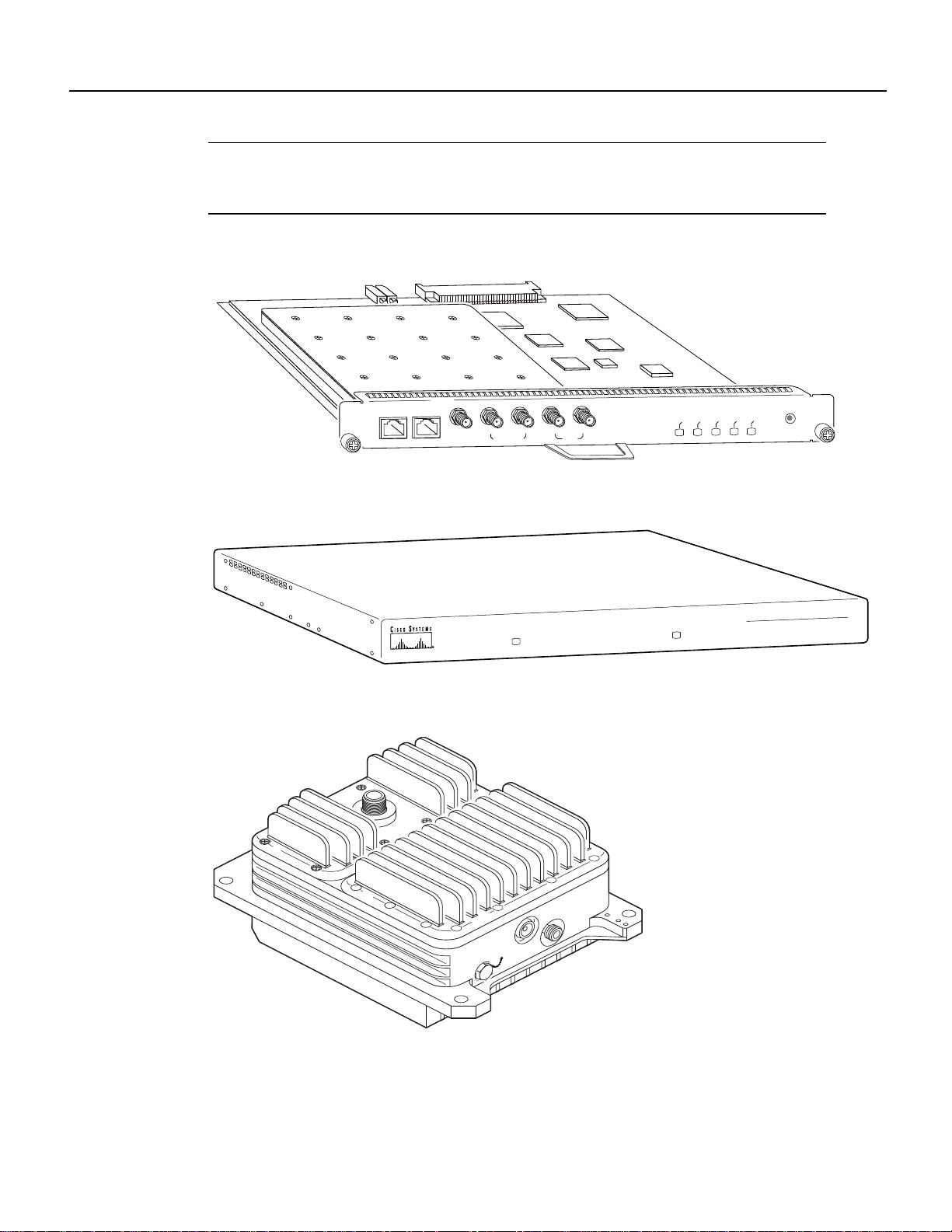
The broadbandfixed wireless system consists of aCisco uBR7200 series universalbroadband router
(Cisco uBR7246 or Cisco uBR7223) and one or more wireless modem cards (see Figure 1), each
with a power feed panel (see Figure 2), and one or two wireless transverters (see Figure 3). (The
diversity option, which minimizes the effects of fading, uses two wireless transverters, one for each
of two antennas.)
2 Cisco uBR7200 Series Universal Broadband Router Wireless Modem Card and Subsystem Installation and Configuration
Final Review - Cisco Internal Use Only
Wireless Modem Card and Subsystem Overview
Note The wireless transverter discussed in this document is manufactured and sold by Cisco for
MMDS links.Transverters forU-NII links must be purchasedfromthird-party vendors. Refer tothat
vendor’s documentation for installation instructions.
Figure 1 Wireless Modem Card
DIVERSITY
MAIN
PFP
MONITOR
PFP
MONITOR
10MHz
CONTROL
IN
DIVERSITY
MAIN
Figure 2 Power Feed Panel
MAIN
POWER ON
Figure 3 Cisco Wireless Transverter for the MMDS Band
DIVERSITY
POWER ON
CARRIER
MAJOR ALARM
MINOR ALARM
OUT OF SERVICE
CISCO uBR – WPFD
POWER FEED PANEL
uBR-MCW-PDA
ENABLED
24272
24262
24863
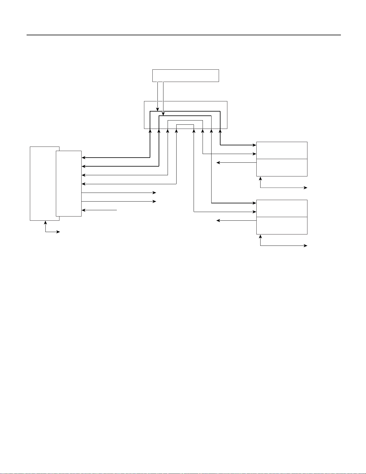
The wireless modem cards are installed in a Cisco uBR7200 series router. Each modem card is
cabled to a power feed panel installed either in the same equipment rack as the router or mounted on
a wall. Cables from the power feed panel are attached to one or two wireless transverters, which are
installed on the antenna mast. The system is managed via a command-line interface (CLI) or
CiscoView. Figure 4 shows the connections between the components.
Cisco uBR7200 Series Universal Broadband Router Wireless Modem Card and Subsystem Installation and Configuration 3
Final Review - Cisco Internal Use Only
Wireless Modem Card and Subsystem Overview
Figure 4 Component Connections
DC Power Supply
Power feed panel
TxRx IF reference (main)
TxRx IF reference (diversity)
UBR7200
series
router
Wireless
modem
card
Console
RF control (main)
RF control (diversity)
Monitor (main)
Monitor (diversity)
Wireless Modem Card
The wireless modem card provides the control and data interface between the system’s digital
motherboard and the radio frequency (RF) subsystem in the wireless transverter.It also provides the
up/down conversion from baseband to intermediate frequency (IF).
Wireless modem cards consist of the following components:
• Main and diversity serial interface control connectors.
• 10-MHz external reference clock connection.
10 MHz reference clock
Main ODU
Test (main)
Duplexer (main)
Antenna (main)
Diversity ODU
Test (diversity)
Duplexer (diversity)
26316
Antenna (diversity)
• Monitor and Power Feed Panel connectors (Main and Diversity)
• Light-emitting diodes (LEDs), which provide a visual indication of the state of the modem card.
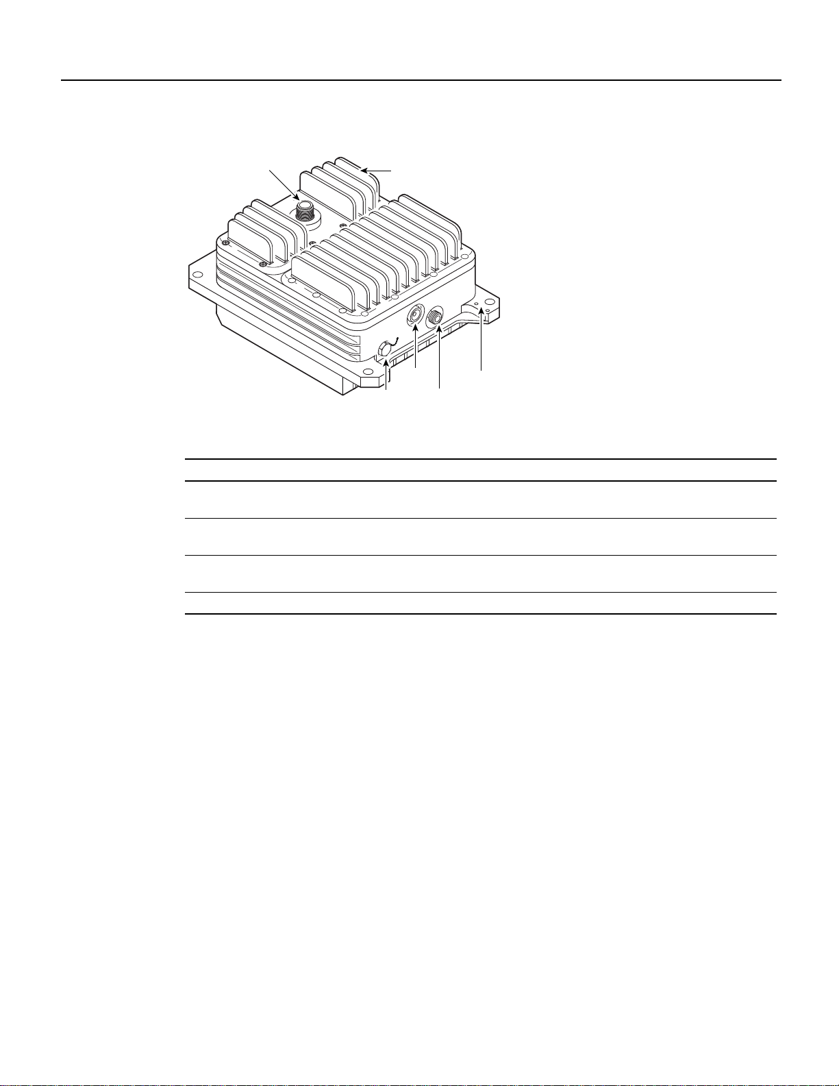
Figure 5 shows the connectors and LEDs on the wireless modem card. Table 1 describes the
functions of the connectors, and Table 2 describes the functions of the LEDs.
4 Cisco uBR7200 Series Universal Broadband Router Wireless Modem Card and Subsystem Installation and Configuration

Final Review - Cisco Internal Use Only
Figure 5 Wireless Modem Card Connectors and LEDs
Wireless Modem Card
MAIN
CARRIER
CARRIER
PFP
MAJOR ALARM
MINOR ALARM
OUT OF SERVICE
OUT OF SERVICE
uBR-MCW-PDA
ENABLED
MINOR ALARM
24257
ENABLED
MAJOR ALARM
MAIN
CONTROL
10MHz
IN
DIVERSITY
MAIN
MONITOR
MONITOR
10MHz
IN
DIVERSITY
DIVERSITY
PFP
DIVERSITY
MONITOR
PFP
MAIN
MONITOR
PFP
CONTROL
Table 1 Wireless Modem Card Connectors
Input/O
Connector Type
utput Function
Control - Main 8-pin RJ-45 (female) Output Physical connection to Power Feed Panel for RF
subsystem interface control channel (main antenna).
Control - Diversity 8-pin RJ-45 (female) Output Physical connection to Power Feed Panel for RF
subsystem interface control channel (diversity antenna
when diversity option is used).
10 MHz Input SMA (female) Input Connection for 10-MHz external reference clock.
Note The system is guaranteed to meet the FCC’s
MMDS-bandfrequency accuracy requirementfor aperiod
of atleast 10 years, without the use of an external 10 MHz
reference. However, if you require greater frequency
accuracy, an externalclock can be attached to the wireless
modem card designated as “master”. (For a list of
accessory suppliers, refer to the Cisco Broadband Fixed
Wireless Site Planning Guide.)
Diversity - Monitor SMA (female) Output For connection to spectrum analyzer for
test/troubleshooting purposes (when diversity option is
used).
Diversity - PFP SMA (female) Output 48 MHz reference, receive and transmit IF signals (when
diversity option is used).
Main - Monitor SMA (female) Output For connection to spectrum analyzer for
test/troubleshooting purposes.
Main - PFP SMA (female) Output 48 MHz reference, receive and transmit IF signals.
Debug Port For factory use only.
Cisco uBR7200 Series Universal Broadband Router Wireless Modem Card and Subsystem Installation and Configuration 5
Final Review - Cisco Internal Use Only
Wireless Modem Card and Subsystem Overview
Table 2 Wireless Modem Card LEDs
LED Function
Carrier LED Indicates the state of the radio link. When green, the radio link is synchronized and the line
protocol is up. When yellow, indicates loss of link synchronization.
Out of Service LED Indicates the service availabilityof the radio link. When yellow, the radio link is still up, butnot
available for use (typically in a test or loopback mode).
Minor Alarm LED When yellow, indicates the occurrence of a minor alarm in the radio subsystem. The link is
degraded and may need maintenance action or, one or more user-defined event thresholds have
been exceeded.
Major Alarm LED When yellow, indicates the occurrence of a major alarm in the radio subsystem. The link is
down.
Enabled LED When green, indicates that the wireless modem card is on, receiving power from the router
midplane, and enabled for operation. This LED remains on during normal operation of the
Cisco uBR7200 series router.
Power Feed Panel
The power feed panel provides DC power, transmit and receive IF signals, frequency reference, and
control signals to the wireless transverter. The unit contains circuit breakers for the DC power, as
well as secondary lightning protection circuitry for the control cables. Local or national codes may
require you to install primary lightning protection for the IF cable and the control cable.
The power feed panel consists of the following components:
• Power LEDs on front and rear panel
• Connector ports
— Coaxial cable connection to the wireless modem card and the wireless transverter (main and
— Control cable connection ports to the wireless modem card and wireless transverter (main
• Power ON/OFF breaker switches (main and diversity)
• DC power supply terminal block
• Ground lug
Figure 6 shows the front panel and Figure 7 shows the rear panel of the power feed panel. Table 3
describes the functions of the LEDs. Table 4 describes the functions of the connectors.
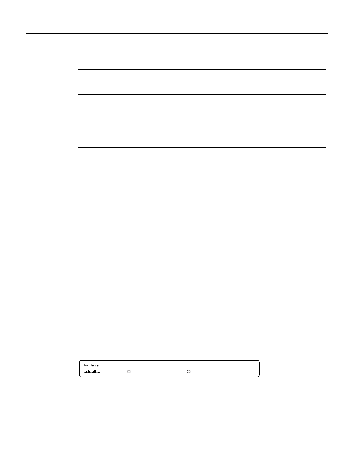
Figure 6 Power Feed Panel (Front Panel)
diversity)
and diversity)
MAIN
POWER ON
6 Cisco uBR7200 Series Universal Broadband Router Wireless Modem Card and Subsystem Installation and Configuration
DIVERSITY
POWER ON
CISCO uBR – WPFD
POWER FEED PANEL
27015
Final Review - Cisco Internal Use Only
Table 3 Power Feed Panel LEDs
LED Function
Main Power On
(visible on front and rear panel)
Diversity Power On
(visible on front and rear panel)
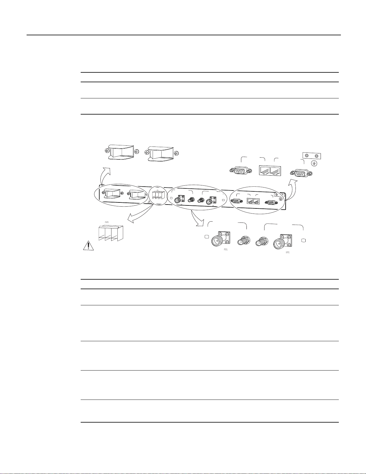
Figure 7 Power Feed Panel (Rear Panel)
When lit, indicates that there is power going to the main transverter.
When lit, indicates that there is power going to the diversity transverter.
Power Feed Panel
MAIN
ON
OFF
CAUTION: This equipment has a connection between the earthed conductor of the
d.c. supply circuit and the earthing conductor. See installation instructions.
DIVERSITY
ON
OFF
ODU
MAIN
MC
DIVERSITY
MC
ODU
CONTROL
MAIN
ON
CAUTION: This equipment has a connection between the earthed conductor of the
d.c. supply circuit and the earthing conductor. See installation instructions.
INPUT
-48V 15A, 720VA
-
CAUTION
USE COPPER
CONDUCTORS ONLY
DIVERSITY
OFF
ON
+
OFF
INPUT
-48V 15A, 720VA
CAUTION
USE COPPER
CONDUCTORS ONLY
PWR
ON
DIVERSITY
ODU
OUTPUT
-48V ,7A
MAIN
ODU
OUTPUT
-48V ,7A
PWR
ON
MC
MC
DIVERSITY
ODU
PWR
ON
OUTPUT
-48V ,7A
ODU
MAIN
MC
MC
MC
CONTROL
DIVERSITY
MC
ODU
MAIN
ODU
OUTPUT
-48V ,7A
PWR
ON
24271
Table 4 Power Feed Panel Connectors
Connector Type Input/Output Function
DC Power Input Pluggable
terminal block
Diversity ODU Output N-Type
(female)
Input Power source connection for the
main and diversity transverters.
Input and Output Provides –48V power to the diversity
transverter, 24-MHz reference,
receiveand transmit IF signal from/to
the wireless modem card (if the
diversity option is used).
Diversity MC (modem
card)
SMA (female) Input and Output Provides 24-MHz reference, receive
and transmit IF signals from/to the
wireless modem card (if the diversity
option is used).
Main ODU Output N-Type
(female)
Input and Output Provides –48V power to the main
transverter, 24-MHz reference
receiveand transmit IF signal from/to
the wireless modem card.
Main MC (modem card) SMA (female) Input and Output Provides 24-MHz reference, receive
and transmit IF signals from/to the
wireless modem card.
Cisco uBR7200 Series Universal Broadband Router Wireless Modem Card and Subsystem Installation and Configuration 7

Final Review - Cisco Internal Use Only
Wireless Modem Card and Subsystem Overview
Table 4 Power Feed Panel Connectors (continued)
Connector Type Input/Output Function
Main ODU Control DB9 (female) Input and Output
Main MC (modem card)
Control
Diversity ODU Control DB9 (female) Input and Output
Diversity MC (modem
card) Control
8-pin RJ-45
(female)
8-pin RJ-45
(female)
Bidirectional data
communications between the
wireless modem card and the
main transverter.
Input and Output
Bidirectional data
communications between the
wireless modem card and the
main transverter.
Bidirectional data
communications between the
wireless modem card and the
diversity transverter.
Input and Output
Bidirectional data
communications between the
wireless modem card and the
diversity transverter.
Physical connection to the main
transverter for RF subsystem control
interface.
Physical connection for RF
subsystem control interface from the
wireless modem card.
Physical connection to the diversity
transverter for RF subsystem control
interface (if the diversity option is
used).
Physical connection for RF
subsystem control interface from the
wireless modem card (if the diversity
option is used).
Wireless Transverter
The ruggedized wireless transverter is the control and data interface to the indoor subsystems. It
provides up/down conversion from IF to RF frequencies and power amplification.
The outdoor unit consists of the following components:
• RF head
• Connector ports for IF input/output, control, and test
• Duplexer assembly with antenna connection
• Ground lug
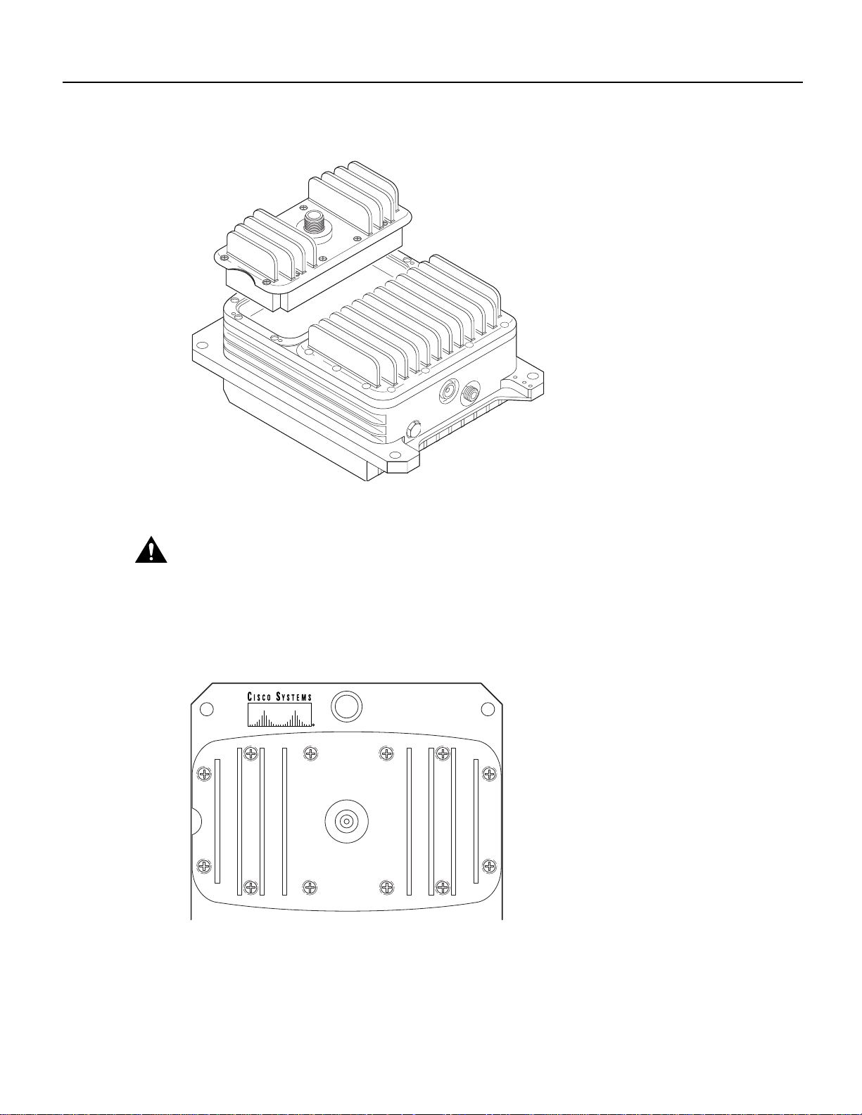
Figure 8 shows the connectors on the wireless transverter, and Table 5 describes their use.
8 Cisco uBR7200 Series Universal Broadband Router Wireless Modem Card and Subsystem Installation and Configuration
Final Review - Cisco Internal Use Only
Field-Replaceable Units
Figure 8 Wireless Transverter and Duplexer Assembly Connectors
Antenna
Table 5 Wireless Transverter and Duplexer Assembly Connectors
Connector Type Input/Output Function
Antenna connector N-type weatherized (female) Input and
IF Input N-type weatherized (female) Input and
Control LEMO (8-pin, R, 1K series) Input and
Test Mono phone (female) 3.5 mm Output Measures voltage for antenna alignment
Duplexer assembly
Control
Test
IF input
Ground
lug
Output
Output
Output
27900
Antenna connection
Carries receive and transmit IF signals and
power
Provides RF subsystem control interface
Field-Replaceable Units
All major components of the broadband fixed wireless system, as well as the major components of
the uBR7200 Series routers are field-replaceable units (FRUs). Each FRU is shipped with
instructions for removal and reinstallation. The following components are available as FRUs:
• Wireless Transverter
• Duplexer for Wireless Transverter
• Power Feed Panel
• Wireless Modem Card
• uBR7200 Series Router Components:
— Network Processing Engine
— Input/Output Controller
— Port Adapters
— Power Supplies
— Fan Tray
— Chassis
Cisco uBR7200 Series Universal Broadband Router Wireless Modem Card and Subsystem Installation and Configuration 9

Final Review - Cisco Internal Use Only
Installation Prerequisites
— Subchassis and Midplane
— Flash Memory Cards
— Rack Mount and Cable-Management Kit
For ordering information, contact a Cisco customer service representative. See the “Cisco
Connection Online” section on page 123 for more information.
Installation Prerequisites
This section providesalistofpartsand tools you need to remove and replace a wireless modem card
in the Cisco uBR7200 series router, install the power feed panel in an equipment rack or on the wall,
and install the wireless transverter at the antenna site. This section also includes safety and
ESD-prevention guidelines to help you avoid injury to yourself and damage to the equipment.
Parts and Tools
The followingsections describe the parts and tools required to install each of the components. If you
need more detailed information regarding cables or connectors, refer to the Cisco Broadband Fixed
Wireless Site Planning Guide.
Wireless Modem Card
You need the following tools and parts to remove and replace a wireless modem card. If you need
additional equipment, contact a service representative for ordering information.
• New wireless modem card
• Number 2 Phillips screwdriver
• Your own ESD-prevention equipment or the disposable grounding wrist strap included with all
• Antistatic mat or surface
• Static shielding bag
• Shielded CAT-5 cable with RJ-45 connectors and plenum-rated coaxial cable with SMA
Power Feed Panel
You need the following tools and parts to install the power feed panel in an equipment rack or on a
wall. If you need additional equipment, contact a service representative for ordering information.
• Power feed panel
• Number 2 Phillips screwdriver
• Bracket kit (provided)
upgrade kits, FRUs, and spares
connectors for connections between the modem card and the power feed panel. (Standard sets of
these cables can be purchased from Cisco.)
• Rack or wall mount screws
• 1/8-inch flat-blade screwdriver
• 5/16-inch open-end wrench
• 50-ohm coaxial cables with N-type (male) connectors for IF control
10 Cisco uBR7200 Series Universal Broadband Router Wireless Modem Card and Subsystem Installation and Configuration

Wireless Transverter
Final Review - Cisco Internal Use Only
Software and Hardware Requirements
• Shielded CAT-5 outdoor-rated control cables with DB-9 (male) and LEMO (8 pin, P,1K series)
connectors (LEMO connector provided)
Note If a lightning protection device is installed between the DB-9 and LEMO connectors,
there may be one logical cable, but two physical cables. The portion of the cable that is located
indoors does not need to be outdoor rated.
• –48VDC power supply
• Ground lug (in grounding kit provided)
You need the following tools and parts to install the wireless transverter. If you need additional
equipment, contact a service representative for ordering information.
Note Installation of some N-type connectors requires specific tools. Obtain this information
from your cable vendor.
• Wireless transverter
• Duplexer assembly
• Number 2 Phillips screwdriver
• Soldering iron/gun
• 9/16-inch open end wrench
• Open end adjustable wrench
• Cable wrap
• Antenna tools (refer to the antenna manufacturer’s instructions)
• Mounting kit (provided)
• 50-ohm coaxial cable with N-type (male) connectors to cable the wireless transverter to the
antenna
• Digital voltmeter with 3.5 mm mono phone plug to use for antenna alignment tasks
• Ground lug (in grounding kit provided)
Software and Hardware Requirements
For this installation and configuration, you need a configured Cisco uBR7200 series router running
Cisco IOS Release 12.0(6)XR or a later 12.0X release, or 12.0(6)T or a later 12.0T release.
Safety Guidelines
Following are safety guidelines that you should follow when working with any equipment that
connects to electrical power or telephone wiring.
Cisco uBR7200 Series Universal Broadband Router Wireless Modem Card and Subsystem Installation and Configuration 11

Final Review - Cisco Internal Use Only
Installation Prerequisites
Safety Warnings
Warning This warning symbol means danger. You are in a situation that could cause bodily injury.
Before you work on any equipment, be aware of the hazards involved with electrical circuitry and
be familiar with standard practices for preventing accidents. To see translations of the warnings that
appear in this publication, refer to the “Regulatory Compliance and Safety Information” section in
this document.
Waarschuwing Dit waarschuwingssymbool betekent gevaar. U verkeert in een situatie die
lichamelijk letsel kan veroorzaken. Voordat u aan enige apparatuur gaat werken, dient u zich bewust
te zijn van de bij elektrische schakelingen betrokken risico's en dient u op de hoogte te zijn van
standaard maatregelen om ongelukken te voorkomen. Voor vertalingen van de waarschuwingen die
in deze publicatie verschijnen, kunt u het gedeelte Regulatory Compliance and Safety Information
(Informatie over naleving van veiligheids- en andere voorschriften) raadplegen in dit document.
Varoitus Tämä varoitusmerkki merkitsee vaaraa. Olet tilanteessa, joka voi johtaa
ruumiinvammaan. Ennen kuin työskentelet minkään laitteiston parissa, ota selvää
sähkökytkentöihin liittyvistä vaaroista ja tavanomaisista onnettomuuksien ehkäisykeinoista. Tässä
julkaisussa esiintyvien varoitusten käännökset löydät tämän asiakirjan Regulatory Compliance and
Safety Information -osasta (määräysten noudattaminen ja tietoa turvallisuudesta).
Attention Ce symbole d'avertissement indique un danger. Vous vous trouvez dans une situation
pouvant causer des blessures ou des dommages corporels. Avant de travailler sur un équipement,
soyez conscient des dangers posés par les circuits électriques et familiarisez-vous avec les
procédures couramment utilisées pour éviter les accidents. Pour prendre connaissance des
traductions d’avertissements figurant dans cette publication, consultez la section Regulatory
Compliance and Safety Information (Conformité aux règlements et consignes de sécurité) de ce
document.
Warnung Dieses Warnsymbol bedeutet Gefahr. Sie befinden sich in einer Situation, die zu einer
Körperverletzungführenkönnte. Bevor Sie mit der Arbeit anirgendeinemGerät beginnen, seien Sie
sich der mit elektrischen Stromkreisen verbundenen Gefahren und der Standardpraktiken zur
Vermeidung von Unfällen bewußt. Übersetzungen der in dieser Veröffentlichung enthaltenen
Warnhinweise finden Sie im Abschnitt "Regulatory Compliance and Safety Information"
(Informationen zu behördlichen Vorschriften und Sicherheit) in diesem Dokument.
Avvertenza Questo simbolo di avvertenza indica un pericolo. La situazione potrebbe causare
infortuni alle persone. Prima di lavorare su qualsiasi apparecchiatura, occorre conoscere i pericoli
relativiai circuiti elettricied essere al correntedelle pratiche standard perla prevenzionedi incidenti.
La traduzione delle avvertenze riportate in questa pubblicazione si trova nella documento
Regulatory Compliance and Safety Information (Conformità alle norme e informazioni sulla
sicurezza) nel presente documento.
Advarsel Dette varselsymbolet betyr fare. Du befinner deg i en situasjon som kan føre til
personskade. Før du utfører arbeid på utstyr, må du vare oppmerksom på de faremomentene som
elektriskekretser innebærer, samtgjøredeg kjent med vanligpraksis når det gjelderå unngå ulykker.
Hvis du vil se oversettelser av de advarslene som finnes i denne publikasjonen, kan du se i avsnittet
Regulatory Compliance and Safety Information (Overholdelse av forskrifter og
sikkerhetsinformasjon) i dette dokumentet.
Aviso Este símbolo de aviso indica perigo. Encontra-se numa situação que lhe poderá causar
danos físicos. Antes de começar a trabalhar com qualquer equipamento, familiarize-se com os
perigosrelacionadoscom circuitos eléctricos,ecom quaisquer práticascomunsque possam prevenir
possíveis acidentes. Para ver as traduções dos avisos que constam desta publicação, consulte a
secção Regulatory Compliance and Safety Information (Informação de Segurança e Disposições
Reguladoras) neste documento.
12 Cisco uBR7200 Series Universal Broadband Router Wireless Modem Card and Subsystem Installation and Configuration
Final Review - Cisco Internal Use Only
Safety Guidelines
¡Advertencia! Este símbolo de aviso significa peligro. Existe riesgo para su integridad física.
Antes de manipular cualquier equipo, considerar los riesgos que entraña la corriente eléctrica y
familiarizarse con los procedimientosestándardeprevención de accidentes. Para ver unatraducción
de las advertencias que aparecen en esta publicación, consultar la sección titulada Regulatory
Compliance and Safety Information (Información sobre seguridad y conformidad con las
disposiciones reglamentarias) que aparece en este documento.
Varning! Denna varningssymbol signalerar fara. Du befinner dig i en situation som kan leda till
personskada. Innan du utför arbete på någon utrustning måste du vara medveten om farorna med
elkretsar och känna till vanligt förfarande för att förebygga skador. Om du vill se översättningar av
de varningar som visas i denna publikation, se avsnittet "Efterrättelse av föreskrifter och
säkerhetsinformation" i detta dokument.
Note This installation must be made in accordance with all local and national regulations. Special
attention must be made to Articles 800, 810, and 820 of the US National Electric Code, Sections 54
and 60 of the Canadian electric code, and equivalentsections of other local and national regulations
that address telecommunications wiring for the control cable, and TV, Radio, and CATV wiring for
the control cable and the coaxial cable.
Warning This product requires short-circuit (overcurrent) protection to be provided as part of the
building installation. Install only in accordance with national and local wiring regulations.
Warning A readily accessible two-pole disconnect device must be incorporated in the fixed wiring.
Electrical Equipment Guidelines
Follow these basic guidelines when working with any electrical equipment:
• Before beginning any procedures requiring access to the chassis interior, locate the emergency
power-off switch for the room in which you are working.
• Disconnect all power and external cables before moving a chassis.
• Do not work alone if potentially hazardous conditions exist.
• Never assume that power has been disconnected from a circuit; always check.
• Do not perform any action that creates a potential hazard to people or makes the equipment
unsafe.
• Never install equipment that appears damaged.
• Carefully examine your work area for possible hazards such as moist floors, ungrounded power
extension cables, and missing safety grounds.
Preventing Electrostatic Discharge Damage
Electrostaticdischarge(ESD) damagesequipmentand impairs electricalcircuitry. ESDoccurs when
printed circuit boards are improperly handled and results in complete or intermittent failures
The network processing engine, I/O controller, port adapters, and wireless modem cards consist of
a printed circuit board that is fixed in a metal carrier. Electromagnetic interference (EMI) shielding,
connectors, and a handle are integral components of the carrier. Handle the network processing
engine, I/O controller, port adapters, and wireless modem cards by their carrier edges and handles;
never touch the printed circuit board when handling either component.
Cisco uBR7200 Series Universal Broadband Router Wireless Modem Card and Subsystem Installation and Configuration 13

Final Review - Cisco Internal Use Only
Installation Prerequisites
Figure 9 shows the location of a printed circuit board when it is installed in a network processing
engine, I/O controller, or Cisco uBR7200 series modem card metal carrier. Do not touch the printed
circuit board when handling any of these components.
Figure 9 Handling the Cisco uBR7200 Series Wireless Modem Cards—Side View
circuit board
Although the metal carrier helps to protect the printed circuit boards from ESD, wear a preventive
antistatic strap whenever handling the network processing engine, I/O controller, port adapters, or
wireless modem cards. Ensure that the strap makes good skin contact and connect the strap’s clip to
an unpainted chassis surface to safely channel unwanted ESD voltages.
Printed
Metal carrier
24258
If no wrist strap is available, ground yourself by touching the metal part of the chassis.
Caution Be sure to tighten the captive installation screws on the network processing engine, the
I/O controller, and the wireless modem cards (use a number 2 Phillips screwdriver). These screws
prevent accidental removal, provide proper grounding for the router, and help to ensure that the
network processing engine, I/O controller, and modem cards are properly seated in the router
midplane.
Following are guidelines for preventing ESD damage:
• Alwaysuse an ESD-preventivewrist strapor ankle strap when installingor replacing the network
processingengine,I/O controller,port adapters, or modem cards.Ensure that the ESD-preventive
strap makes contact with your skin.
• Handle the network processing engine, I/O controller, port adapters, or modem cards by their
metal carrier edgesandhandles only; avoid touching theprintedcircuit board components or any
connector pins.
• When removing the networkprocessing engine, I/O controller, port adapters, or wireless modem
cards, place them on an antistatic surface with the printed circuit board components facing
upward, or in a static shielding bag. If you are returning an I/O controller, network processing
engine, port adapter, or modem card to the factory, immediately place it in a static shielding bag.
Caution Periodically check the resistance value of the antistatic strap. The measurement should be
within the range of 1 to 10 megohms (Mohm).
Warning Do not work on the system or connect or disconnect cables during periods of lightning
activity.
14 Cisco uBR7200 Series Universal Broadband Router Wireless Modem Card and Subsystem Installation and Configuration

Final Review - Cisco Internal Use Only
Product Disposal
Warning Read the installation instructions before you connect the system to its power source.
Warning Before working onequipment that is connectedto power lines,remove jewelry(including
rings, necklaces, and watches). Metal objects will heat up when connected to power and ground and
can cause serious burns or weld the metal object to the terminals.
Warning Care must be given to connecting units to the supply circuit so that wiring is not
overloaded.
Warning This equipment is to be installed and maintained by service personnel only as defined by
AS/NZS 3260.
Warning Only trained and qualified personnel should be allowed to install, replace, or service this
equipment.
Product Disposal
Warning Ultimate disposal of this product should be handled according to all national laws and
regulations.
Compliance with U.S. Export Laws and Regulations Regarding Encryption
This product performs encryption (in the baseline privacy feature) and is regulated for export by the
U.S.Government. Followingis specific informationregarding compliance withU.S. exportlawsand
regulations for encryption products:
• This product is not authorized for use by persons located outside the United States and Canada
that do not have export license authority from the U.S. Government.
• This product may not be exported outside the U.S. and Canada either by physical or electronic
means without the prior written approval of the U.S. Government.
• Persons outside the U.S. and Canada may not reexport, resell, or transfer this product by either
physical or electronic means without prior written approval of the U.S. Government.
Removing and Installing a Wireless Modem Card
The following sections explain how to remove and replace or install a wireless modem card in a
Cisco uBR7200 series router.
Removing a Wireless Modem Card
The following procedures explain how to remove a wireless modem card from a Cisco uBR7200
series router:
Step 1 Attach an ESD-preventive wrist strap between you and an unfinished chassis surface.
Step 2 Unscrew the captive installation screws on the front of the wireless modem card. (See
Figure 10.)
Cisco uBR7200 Series Universal Broadband Router Wireless Modem Card and Subsystem Installation and Configuration 15

Final Review - Cisco Internal Use Only
Removing and Installing a Wireless Modem Card
Figure 10 Captive Installation Screws
MAIN
Captive
installation screw
CONTROL
DIVERSITY
10MHz
MINOR ALARM
OUT OF SERVICE
IN
DIVERSITY
MAIN
PFP
MONITOR
PFP
MONITOR
CARRIER
uBR-MCW-PDA
ENABLED
MAJOR ALARM
installation screw
24259
Captive
Step 3 Grasp the handleonthe wireless modem card and carefully pull the modem card fromthe
midplane, about halfway out of its slot. If you are removing a blank modem card, pull the
blank modem card all the way out of the chassis slot.
Step 4 Withthe wireless modem cardhalfway out of theslot,disconnect all cables from thefront
of the modem card.
Note Do not disconnectthecables until the modem card is pulled halfway out ofitsslot.
Doing so can disrupt normal operation of the router.
Step 5 After disconnecting the cables, pull the modem card from its chassis slot.
Caution Always handle the wireless modem card by the carrier edges and handle; never touch the
modem card’s components or connector pins. (See Figure 9.)
Step 6 Place the modem card on an antistatic surface with its components facing upward, or in
a static shielding bag. If the modem card will be returned to the factory, immediately
place it in a static shielding bag.
This completes the procedure for removing a wireless modem card from the Cisco uBR7200 series
router.
Installing or Replacing a Wireless Modem Card
Complete the following steps to install or replace a wireless modem card in the Cisco uBR7200
series router:
Step 1 Attach an ESD-preventive wrist strap between you and an unfinished chassis surface.
Step 2 Grasp the modem card by its metal carrier edges and position the modem card as shown
in Figure 9.
Step 3 Align the left and right edges of the modem card metal carrier between the guides in the
modem card slot. (For the Cisco uBR7246, see Figure 11. For the Cisco uBR7223, see
Figure 12.)
16 Cisco uBR7200 Series Universal Broadband Router Wireless Modem Card and Subsystem Installation and Configuration

Final Review - Cisco Internal Use Only
DIVERSITY
CONTROL
10MHz
IN
MONITOR
DIVERSITY
MAIN
PFP
MONITOR
uBR-MCW-PDA
CARRIER
OUT OF SERVICE
MINOR ALARM
MAJOR ALARM
PFP
MAIN
ENABLED
Installing or Replacing a Wireless Modem Card
Figure 11 Aligning the Wireless Modem Card Metal Carrier Between the Slot Guides
(Cisco uBR7246 Shown)
24261
Cisco uBR7200 Series Universal Broadband Router Wireless Modem Card and Subsystem Installation and Configuration 17

Final Review - Cisco Internal Use Only
DIVERSITY
CONTROL
10MHz
IN
MONITOR
DIVERSITY
MAIN
PFP
MONITOR
uBR-MCW-PDA
CARRIER
OUT OF SERVICE
MINOR ALARM
MAJOR ALARM
PFP
MAIN
ENABLED
Removing and Installing a Wireless Modem Card
Figure 12 Aligning the Wireless Modem Card Metal Carrier Between the Slot Guides
(Cisco uBR7223 Shown)
24260
Step 4
Withthe metal carrieraligned in the slotguides,gently slide the modemcard halfway into
the modem card slot.
Caution Do not slidethe modem card all the way into the slotuntilyou have connected all required
cables. Trying to do so will disrupt normal operation of the router.
Step 5 With the modem card halfway in the slot, connect all required cables to the front of the
modem card. (See the “Cabling a Wireless Modem Card” section on page 19.)
Step 6 After connecting all required cables, carefully slide the modem card all the way into the
slot until you feel the card’s connectors mate with the midplane.
Step 7 Tighten the captive installation screws on the modem card. (See Figure 10.)
Note If the modem card captive installation screws do not tighten all the way, the card
is not completely seated in the midplane. Carefully pull the modem card halfway out of
the slot, reinsert it, and tighten the captive installation screws.
Caution Care must be taken when installing the wireless modem cards to not overtighten and strip
the captive screws. Never use a screw gun or similar device when installing these cards.
Caution To ensure adequate airflow across the router’s modem cards, a modem card or blank
modem card (faceplate) must be installed in each modem card slot.
18 Cisco uBR7200 Series Universal Broadband Router Wireless Modem Card and Subsystem Installation and Configuration
Final Review - Cisco Internal Use Only
Warning Blank faceplatesand cover panels serve three important functions: they preventexposure
to hazardous voltages and currents inside the chassis; they contain electromagnetic interference
(EMI) thatmight disrupt other equipment; and theydirect the flow of coolingair through the chassis.
Do not operate the system unless all cards, faceplates, front covers, and rear covers are in place.
This completes the procedure for installing a wireless modem card in the Cisco uBR7200 series
router.
Cabling a Wireless Modem Card
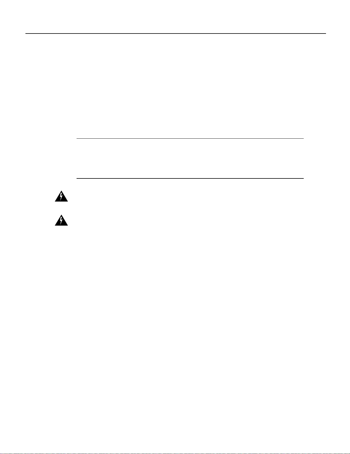
Attaching the RF Control Cable
Insert the RJ-45 connector on the control cable into the Main Control connector port. (See
Figure 13.)
Figure 13 Attaching the RF Control Cable
Cabling a Wireless Modem Card
If you will be using the diversity option, use a second cable and attach it to the Diversity Control
connector port.
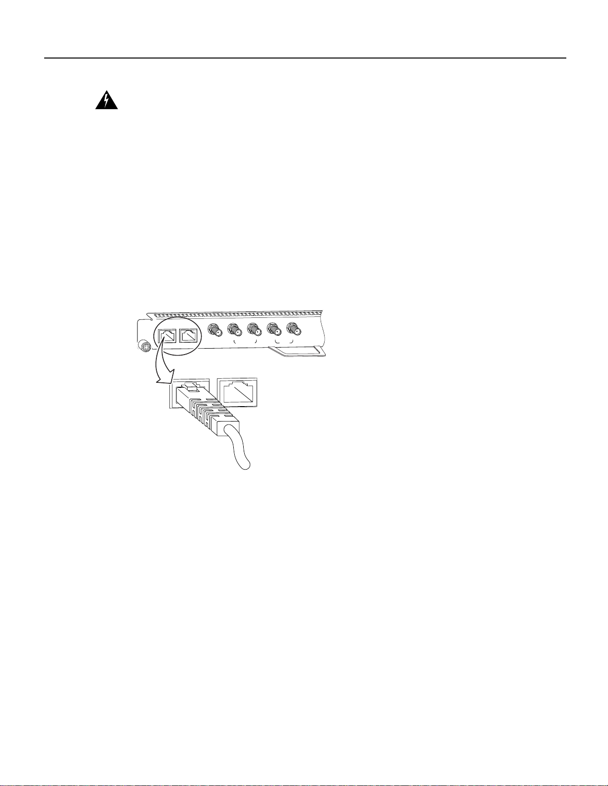
Attaching the IF Cable
Connect one end of the IF signal cable to the Main PFP (power feed panel) port. (See Figure 14.)
MAIN
CONTROL
DIVERSITY
MAIN
10MHz
IN
DIVERSITY
CONTROL
MONITOR
DIVERSITY
PFP
MONITOR
PFP
MAIN
28537
Cisco uBR7200 Series Universal Broadband Router Wireless Modem Card and Subsystem Installation and Configuration 19
Final Review - Cisco Internal Use Only
Installing a Power Feed Panel
Figure 14 Attaching the IF Cable
10MHz
IN
MONITOR
DIVERSITY
MONITOR
10MHz
IN
If you will be using the diversity option, use a second cable and attach it to the Diversity PFP port.
(Optional) Attaching the Monitor Cable
To use a spectrum analyzerto test or troubleshoot the signal on the modem card,attachit to the Main
Monitor port or Diversity Monitor port.
(Optional) Cabling the 10 MHz Clock
To connect to a 10 MHz clock to the master wireless modem card, connect an SMA to BNC adapter
to the 10 MHz IN connector port. Attach the clock cable’s BNC connector to the adapter.
Note Recommended torque for attaching connectors to SMA ports is 7 to 10 inch pounds.
This completes the procedure for cabling a wireless modem card.
DIVERSITY
PFP
MAIN
28538
MAIN
PFP
MONITOR
PFP
MONITOR
PFP
Installing a Power Feed Panel
A power feed panel can be mounted in a 19-inch rack or mounted on a wall. Depending on your site
requirements, the unit can be co-located with the router or placed at an indoor location near the
bulkhead opening leading to the outdoor wireless transverter.
Note When rack mounting the power feed panel, allow at least one rack unit space between the
uBR and the power feed panel or between multiple power feed panels.
Rack-Mounting a Power Feed Panel
A power feed panel can be rack-mounted with either the front panel or the rear panel facing forward
depending on the cable handling requirements of your site, or in a center-mount telco rack. The
power LEDs are visible on both the front and rear panels.
Warning To prevent bodily injury when mounting or servicing this unit in a rack, you must take
special precautions to ensure that the system remains stable. The following guidelines are provided
to ensure your safety:
— This unit should be mounted at the bottom of the rack if it is the only unit in the rack.
20 Cisco uBR7200 Series Universal Broadband Router Wireless Modem Card and Subsystem Installation and Configuration

Final Review - Cisco Internal Use Only
Warning This unit is intended for installation in restricted access areas. A restricted access area is
where access can only be gained by service personnel through the useofaspecialtool, lock and key,
or other means of security, and is controlled by the authority responsible for the location.
Attaching the Brackets
To install a power feed panel with the front panel facing forward, attach the brackets to both sides of
the unit. (See Figure 15.)
Figure 15 Bracket Installation - Front Panel Forward
Rack-Mounting a Power Feed Panel
— When mounting this unit in a partially filled rack, load the rack from the bottom to the top
with the heaviest component at the bottom of the rack.
— If the rack is provided with stabilizing devices, install the stabilizers before mounting or
servicing the unit in the rack.
uBR – WPFD
FEED PANEL
24265
To install a power feed panel with the rear panel facing forward, attach the brackets to both sides of
the unit. (See Figure 16.)
Figure 16 Bracket Installation - Rear Panel Forward
IN
DIVERSITY
MC
MC
ODU
CONTROL
24266
To install a power feed panel in a center-mount telco rack, attach the brackets to both sides of the
unit. (See Figure 17.)
Figure 17 Telco Center-Mount Bracket Installation - Rear Panel Forward
IN
DIVERSITY
MC
MC
ODU
CONTROL
24267
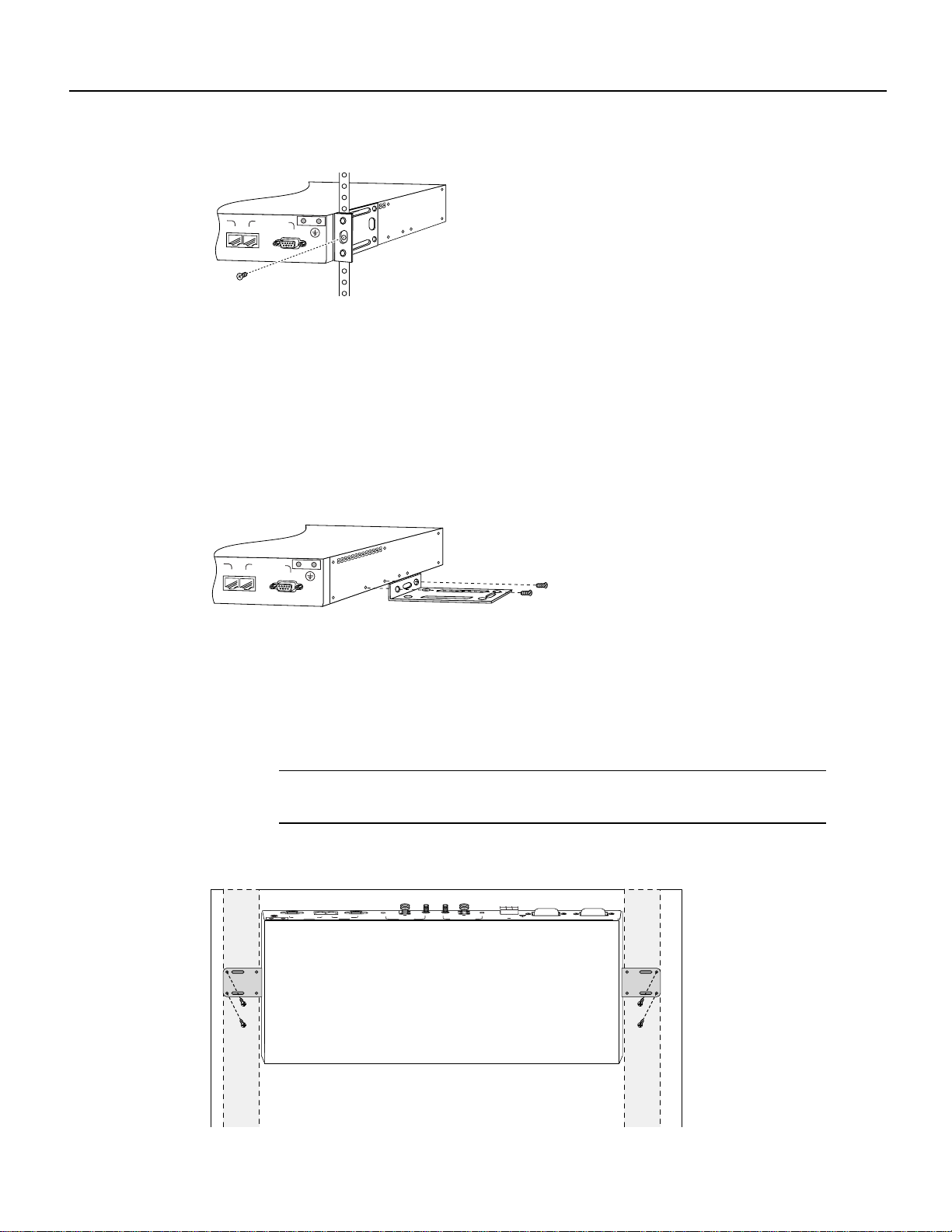
Installing the Power Feed Panel in the Equipment Rack
After the brackets are secured, attach the brackets on both sides of the power feed panel to the
equipment rack. (See Figure 18.)
Cisco uBR7200 Series Universal Broadband Router Wireless Modem Card and Subsystem Installation and Configuration 21
Final Review - Cisco Internal Use Only
Installing a Power Feed Panel
Figure 18 Attaching the Power Feed Panel to an Equipment Rack
IN
DIVERSITY
MC
MC
ODU
CONTROL
Wall-Mounting the Power Feed Panel
To wall-mount the unit, use the same brackets as those used to install the power feed panel in an
equipment rack.
Use the following steps to wall-mount the power feed panel:
Step 1 Attach the brackets to both sides of the power feed panel. (See Figure 19.)
Figure 19 Attaching the Wall Mount Brackets
24268
IN
DIVERSITY
MC
MC
ODU
CONTROL
24269
Step 2
Attach the power feed panel to the wall (see Figure 20), using screws and anchors you
provide.To best support thepowerfeed panel and cables, make sure the powerfeed panel
is attached securely to a vertical wall stud or to a firmly attached plywood mounting
backboard. This position will prevent the unit from pulling away from the wall when the
cables are attached.
Note To allow the proper air flow through the unit when attached to a wall, the power
feed panel must be installed with the rear panel connectors pointing up.
Figure 20 Wall-Mounting the Power Feed Panel
MC
ODU
MC
MC
DIVERSITY
CONTROL
ON
ODU
MAIN
-48 ,7A
PWR
OUTPUT
ODU
MAIN
ON
MC
-48 ,7A
PWR
OUTPUT
ODU
DIVERSITY
OFF
CONDUCTORS ONLY
USE COPPER
CAUTION
-48v 15a, 720VA
INPUT
ON
ON
OFF
conductor. See installation instructions.
earthed conductor of the d.c. supply circuit and the earthing
CAUTION: This equipment has a connection between the
27296
22 Cisco uBR7200 Series Universal Broadband Router Wireless Modem Card and Subsystem Installation and Configuration
Final Review - Cisco Internal Use Only
Attaching the Ground Lug
A ground lug kit is provided with the power feed panel. Use the following steps to attach the ground
lug to the power feed panel chassis.
Step 1 Attach an approved ground wire to the ground lug.
Step 2 Locate the two ground lug threaded holes on the upper right of the rear panel.
Step 3 Align the ground lug with the threaded holes and fasten it to the chassis using the two
screws included in the kit. (See Figure 21.)
Figure 21 Attaching the Ground Lug
IN
DIVERSITY
MC
MC
CONTROL
ODU
Attaching the Ground Lug
27284
Step 4
Wiring the DC Power
Follow the procedures in this section to wire the DC power.
Note The color coding of DC-input power supply leads depends on the color coding of the DC
powersource at your site.Typically, greenor green/yellow isused for ground, blackis used for +48V
(return), and red or white is used for –48V. Make certain the lead color coding you choose for the
DC-input power supply matches lead color coding at the DC power source.
Warning This product requires short-circuit (overcurrent) protection to be provided as part of the
building installation. Install only in accordance with national and local wiring regulations.
Warning This equipment has a connection between the earthed conductor of the DC supply circuit
and the earthing conductor.
1) This equipment shall be connected directly to the DC supply system earthing electrode conductor
or to a bonding jumper from an earthing terminal bar or bus to which the DC supply system earthing
electrode is connected.
2) This equipment shall be located in the same immediate area (such as adjacent cabinets) as any
other equipment that has a connection between the earthed conductor of the same DC supply circuit
and the earthing conductor, and also the point of earthing of the DC system. The DC system shall
not be earthed elsewhere.
Using a number 2 Phillips screwdriver, tighten the screws.
3) The DC supply source is to be located within the same premises as this equipment.
4) There shall be no switching or disconnecting devices in the earthed circuit conductor between the
DC source and the point of connection on the earthing electrode conductor.
Warning Secure all power cabling when installing this unit to avoid disturbing field-wiring
connections.
Cisco uBR7200 Series Universal Broadband Router Wireless Modem Card and Subsystem Installation and Configuration 23
Final Review - Cisco Internal Use Only
Installing a Power Feed Panel
Warning When installing the unit, the ground connection must always be made first and
disconnected last.
Warning Figure 23 shows the DC power supply terminal block. Wire the DC power supply using
the appropriate wire terminations at the wiring end, as illustrated. The proper wiring sequence is
ground to ground, positive to positive (line to L), and negative to negative (neutral to N). Note that
the ground wire should always be connected first and disconnected last.
Warning A readily accessible two-poled disconnect device must be incorporated in the fixed
wiring.
Warning Use copper conductors only.
Warning An exposed wire lead from a DC-input power source can conduct harmful levels of
electricity. Be sure that no exposed portion of the DC-input power source wire extends from the
terminal block plug.
Warning The customer 48 volt power system must provide reinforced insulation between the
primary AC power and the 48 VDC output.
Warning Connect the unit only to a DC power source that complies with the Safety Extra-Low
Voltage (SELV) requirements in IEC 60950 based safety standards.
Warning Before performing any of the following procedures, ensure that power is removed from
the DC circuit. To ensure that all power is OFF, locate the circuit breaker on the panel board that
services the DC circuit, switch the circuit breaker to the OFF position, and tape the switch handle of
the circuit breaker in the OFF position.
Wiring the DC power consists of attaching the wires of the DC power source to a removable wiring
block, then plugging that block into the connection on the power feed panel. Refer to Figure 24 and
Figure 25 and follow these steps.
Note Use 14 AWG or larger wire to wire the DC input power supply to the power feed panel.
Step 1 Ensure that the leads are disconnected from the power source.
Step 2 Ensure that the power/breakerswitch for both main and diversity are in the OFF position.
(See Figure 22.)
24 Cisco uBR7200 Series Universal Broadband Router Wireless Modem Card and Subsystem Installation and Configuration
Final Review - Cisco Internal Use Only
Wiring the DC Power
Figure 22 Wireless Transverter Power/Breaker Switches
MAIN DIVERSITY
ON
OFF
CAUTION: This equipment has a connection between the earthed conductor of the
d.c. supply circuit and the earthing conductor. See installation instructions.
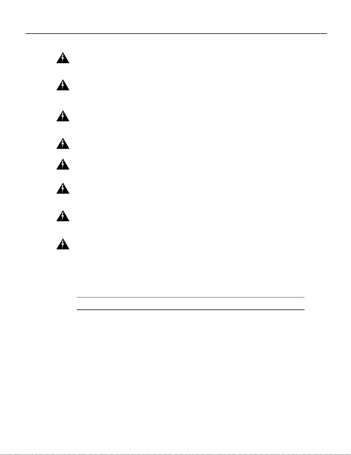
Step 3 Using a wire stripper,strip approximately 0.25 inch (6.35 mm) from the +48V, –48V, and
ground leads.
Figure 23 Stripping the Wire
ON
OFF
27908
.25 in.
(6.35 mm)
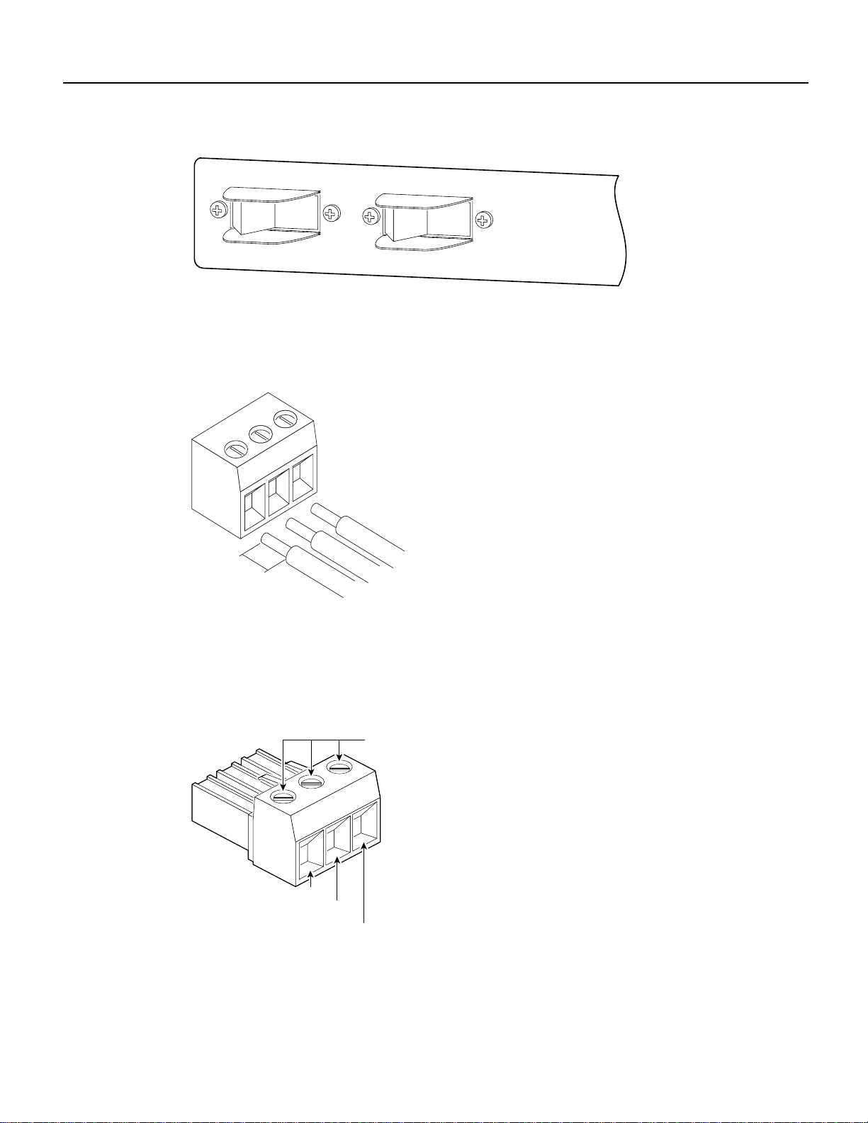
Step 4
Insertthestripped ends of thewirein the removablewiring block according tothe scheme
in Figure 24. Figure 24 illustrates the polarity of each connection. The connection on the
left is for the –48 VDC wire, the middle connection is for safety ground. The connection
on the right is for the positive return wire.
Figure 24 Wiring Connections
Securing
screws
24919
-48 VDC
Safety
ground
+48 VDC
return
Secure the wires using the 1/8-inch blade screwdriver to tighten the screws in the top of
the terminal block.
27285
Step 5 Connect the DC input wiring to the DC source.
Cisco uBR7200 Series Universal Broadband Router Wireless Modem Card and Subsystem Installation and Configuration 25

Final Review - Cisco Internal Use Only
Installing a Power Feed Panel
Warning For personal safety, the ground wire must connect to safety (earth) ground at both the
equipment and supply side of the DC wiring (unless the local electrical code requirements are
different).
Step 6 Plug the terminal block into the receptacle on the power feed panel. (See Figure 25.)
Figure 25 Plugging the Terminal Block into the Receptacle
24920
Cabling the Power Feed Panel
This section describes the cabling of the power feed panel.
Warning Never defeat the ground conductor or operate the equipment in the absence of a suitably
installed ground conductor. Contact the appropriate electrical inspection authority or an electrician
if you are uncertain that suitable grounding is available.
Note It is not necessary to terminate unused connectors.
Connecting the Control Cable (from the Wireless Modem Card)
Attach the end of the control cable coming from the Control-Main port on the modem card to the
Control-Main/MC port on the power feed panel. (See Figure 26.)
Figure 26 Connecting the Control Cable (from the Wireless Modem Card)
ODU
MAIN
MAIN
ODU
MC
CONTROL
DIVERSITY
MC
MC
CONTROL
DIVERSITY
MC
ODU
ODU
28539
26 Cisco uBR7200 Series Universal Broadband Router Wireless Modem Card and Subsystem Installation and Configuration

Final Review - Cisco Internal Use Only
If you will be using the diversity option, also attach the second control cable coming from the
Control-Diversity port on the modem card to the Control-Diversity/MC port on the power feed
panel.
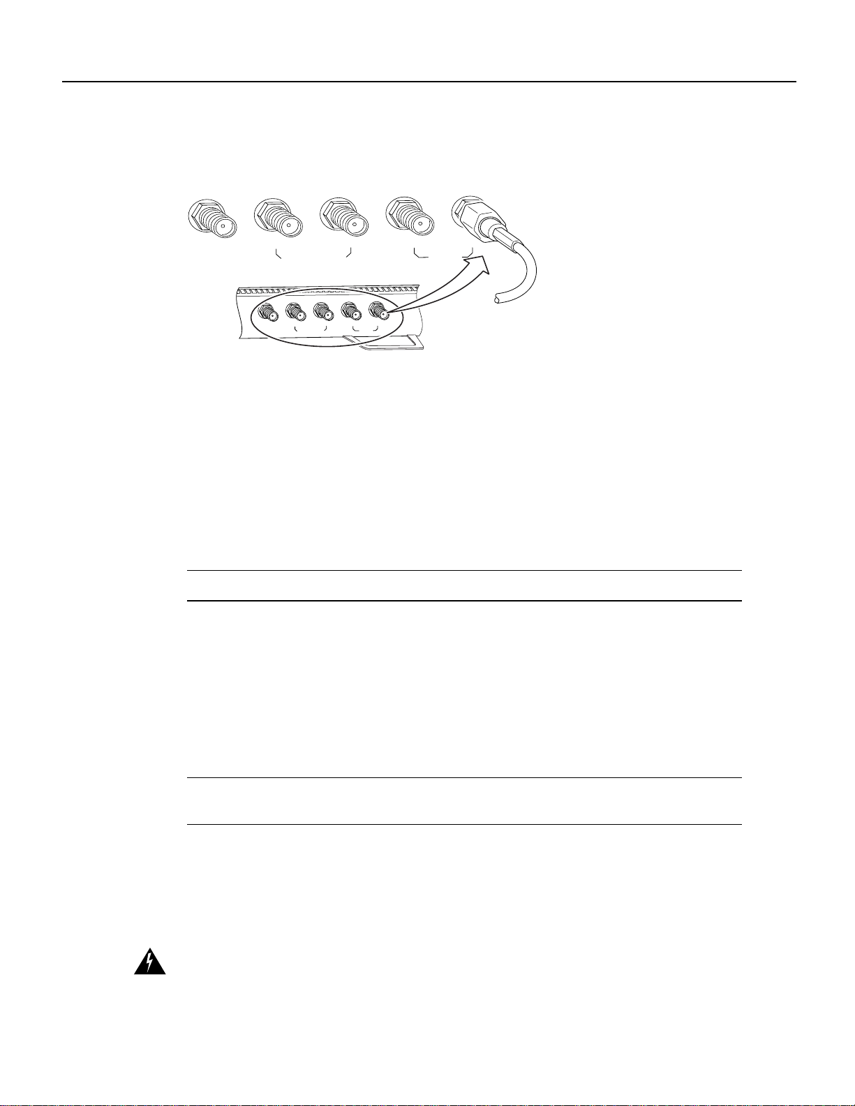
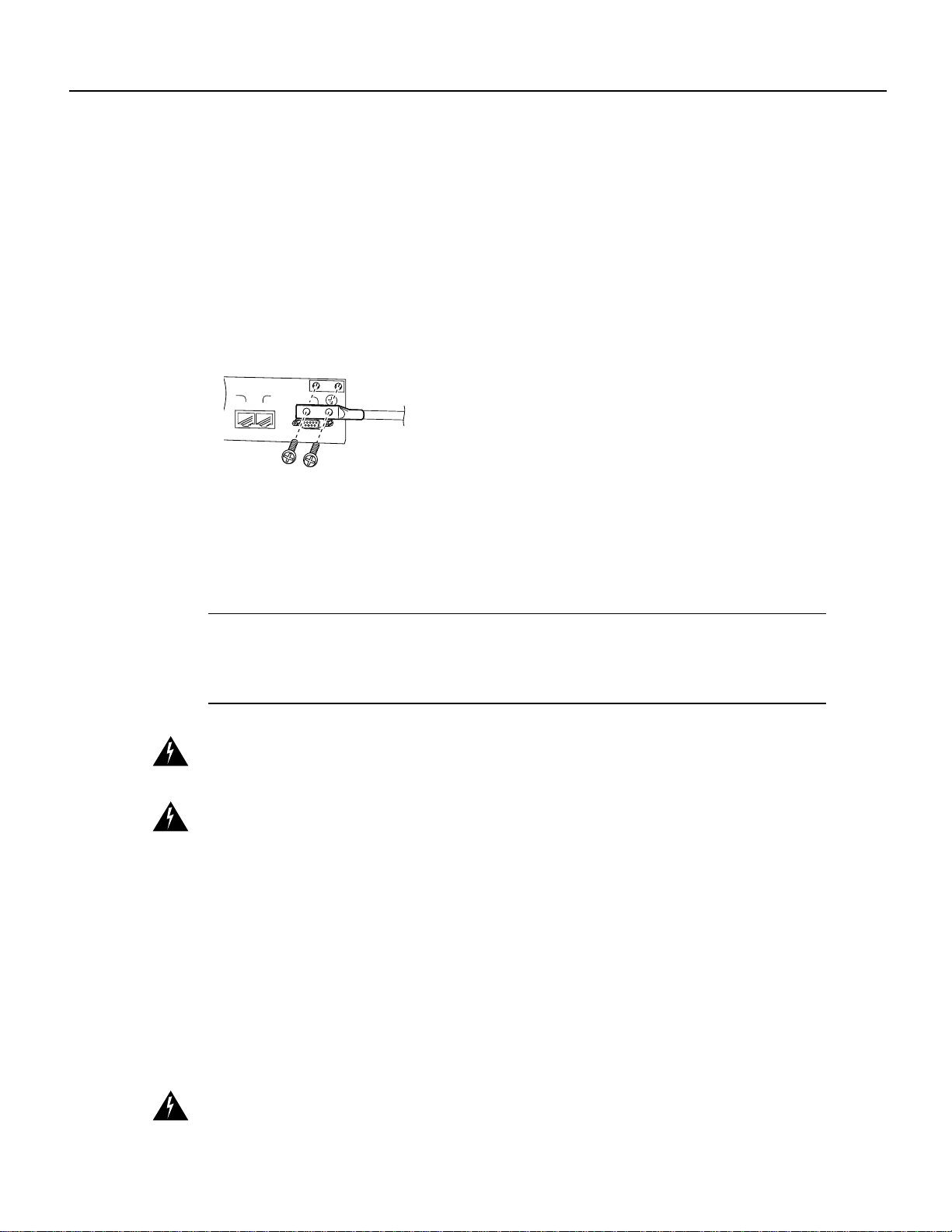
Connecting the Control Cable (to the Wireless Transverter)
Attach a cable with a DB-9 connector to the Control-Main/ODU port on the power feed panel. (See
Figure 27.)
Figure 27 Connecting the Control Cable (to the Wireless Transverter)
Cabling the Power Feed Panel
MAIN
ODU
If you will be using the diversity feature, attach a second cable to the Control-Diversity/ODU port.
Warning To reduce the risk of fire, use only No. 26 AWG or larger telecommunication line cord.
Connecting the IF Cable (from the Wireless Modem Card)
Connect the cable coming from the Main/PFP port of the modem card to the Main/MC port on the
power feed panel. If stiff coaxial cable has been used for the connection, first attach a “pigtail”
adapter using flexible coaxial cable. (See Figure 28.)
Figure 28 Connecting the IF Cable (from the Wireless Modem Card)
PWR
ON
DIVERSITY
PWR
ODU
ON
OUTPUT
-48V ,7A
DIVERSITY
ODU
MC
MAIN
ODU
OUTPUT
-48V ,7A
PWR
ON
MC
MC
MC
ODU
MAIN
MC
CONTROL
MC
MC
CONTROL
MAIN
ODU
DIVERSITY
MC
ODU
MAIN
ODU
DIVERSITY
DIVERSITY
MC
MC
CONTROL
PWR
ON
ODU
ODU
28540
OUTPUT
-48V ,7A
OUTPUT
-48V ,7A
28541
If you will be using the diversity feature, also connect the cable coming from the Diversity/PFP port
of the modem card to the Diversity/MC port on the power feed panel.
Connecting the IF Cable (to the Wireless Transverter)
Attach one end of the IF cable to the Main-ODU/Output connector. (See Figure 29.) If stiff coaxial
cable is being used for the connection, first attach a “pigtail” adapter using flexible coaxial cable.
Cisco uBR7200 Series Universal Broadband Router Wireless Modem Card and Subsystem Installation and Configuration 27

Installing a Wireless Transverter
Warning Use RG-214 orsimilarsize 50-ohm coaxialcablewith a centerconductorsize of 14 AWG
or larger. Failure to do so can result in overheating and long-term failure.
Figure 29 Connecting the IF Cable (to the Wireless Transverter)
PWR
ON
DIVERSITY
ODU
OUTPUT
-48V ,7A
MC
MAIN
ODU
OUTPUT
-48V ,7A
PWR
ON
MC
DIVERSITY
PWR
ON
ODU
OUTPUT
-48V ,7A
MC
MC
If you will be using the diversity feature, attach a second cable to the Diversity-ODU/Output
connector.
This completes the procedure for installing and cabling a power feed panel.
Installing a Wireless Transverter
Thissectionprovides instructions forinstalling the duplexerassembly in thetransverterchassis, then
installing the transverter on the antenna mast.
Note These instructions apply to the MMDS transverter manufactured and supplied by Cisco. If
you have purchased a transverter from another vendor, refer to that vendor’s instructions for
installation.
MAIN
ODU
OUTPUT
-48V ,7A
PWR
ON
28542
Warning Do not locate the transverter near overhead power lines or other electric light or power
circuits, or where it can come into contact with such circuits. (See Figure 30.) When installing the
transverter,take extreme care not to come into contact with such circuits, as they may cause serious
injury and death.
28 Cisco uBR7200 Series Universal Broadband Router Wireless Modem Card and Subsystem Installation and Configuration

Figure 30 Roof Installation Considerations
Antenna
Installing a Wireless Transverter
NEC Article 810
CEC Section 54
Warning
This unit is intended for installation in restricted access areas. A restricted access area is
Mast
Wireless
Transverter
Control Cable
NEC Article 800
CEC Article 60
IF Power Cable
NEC Article 820
CEC Section 54
27290
where access can only be gained by service personnel through the useofaspecialtool, lock and key,
or other means of security, and is controlled by the authority responsible for the location.
Warning When installing the unit, the ground connection must always be made first and
disconnected last.
Warning Never defeat the ground conductor or operate the equipment in the absence of a suitably
installed ground conductor. Contact the appropriate electrical inspection authority or an electrician
if you are uncertain that suitable grounding is available.
Warning A radiation hazard may exist within a specific radius around the center point of the
antenna. The table below associates antenna gain (in dB) with a minimum acceptable distance.
Determine the gain of the antenna and use Table 6 to locate the minimum acceptable distance from
the center point of the antenna. (Transmitter Power = 33 dBi.)

Installing a Wireless Transverter
Table 6 Radiation Hazard Calculation (continued)
Minimum Acceptable
Antenna
Gain
(dBi)
14 47 50.1 0.6 0.3
15 48 63.1 0.7 0.3
16 49 79.4 0.8 0.4
17 50 100.0 0.9 0.4
18 51 125.9 1.0 0.4
19 52 158.5 1.1 0.5
20 53 199.5 1.3 0.6
21 54 251.2 1.4 0.6
22 55 316.2 1.6 0.7
23 56 398.1 1.8 0.8
24 57 501.2 2.0 0.9
25 58 631.0 2.2 1.0
26 59 794.3 2.5 1.1
27 60 1000.0 2.8 1.3
28 61 1258.9 3.2 1.4
29 62 1584.9 3.6 1.6
30 63 1995.3 4.0 1.8
EIRP
(dBm)
EIRP
(W)
Distance under FCC Rules
– Uncontrolled
Environment (m)
Minimum Acceptable
Distance under FCC Rules
– Controlled Environment
(m)
Installing the Duplexer in the Wireless Transverter
Installing a wireless transverter requires the installation of the duplexer assembly prior to mounting
the transverter on the antenna mast.
The duplexer acts as a filter for Tx/Rx isolation. The duplexer assembly is shipped as a separate unit
based on the RF channel plan you have selected for your installation.
Note The channel selection must be entered using the radio operating band command from the
command-line interface. See “show interfaces radio (arq)” section on page 66.
30 Cisco uBR7200 Series Universal Broadband Router Wireless Modem Card and Subsystem Installation and Configuration

Figure 31 Duplexer Assembly
Notched end
Installing the Duplexer Assembly in the Wireless Transverter
The orientationofthe duplexer assembly wheninstalledin the transverter will determine itstransmit
and receive frequency.
Installing the Duplexer in the Wireless Transverter
27288
Note The orientation of one end of a point-to-point link must be opposite to that of the other end
of the link. In addition, the choice of Tx Hi or Rx Hi must match the frequencies configured for the
wireless modem card using the command-line interface or CiscoView.
Use the following steps to install the duplexer in the transverter.
Step 1 Determine if you will be using the high frequency band for transmitting or receiving.
Step 2 Detach thebottom portion of the labelaffixed to theunder side of the duplexer, andrecord
the duplexerorientation. (See Figure 32.) This label can be attachedto equipment records
and used for reference when configuring the system or performing maintenance.
Figure 32 Frequency Assignment Label
CISCO uBR-ODD-05A
HI: 2632-2644 MHz
LO: 2596-2608 MHz
Detach Label Here Prior To Installation
CISCO uBR-ODD-05A
HI: 2632-2644 MHz
LO: 2596-2608 MHz
Tx Hi Rx Hi
800-01234-01 A0 CAB01230001
Step 3
Match the notched end of the duplexerwith either the Tx Hi or Rx Hi side of the duplexer
28306
receptacle in the wireless transverter. (See Figure 33.)
Cisco uBR7200 Series Universal Broadband Router Wireless Modem Card and Subsystem Installation and Configuration 31

Installing a Wireless Transverter
Figure 33 Duplexer Receptacle in the Wireless Transverter
Tx Hi
Tx Hi
Step 4
Verify that the gasket is aligned in the groove in the transverter chassis. (See Figure 34.)
Figure 34 Gasket in the Transverter Chassis
Rx Hi
Rx Hi
27286
Rx Hi
Tx Hi
27287
Gasket
Step 5
Carefully line up the duplexer and plug it into the chassis, being careful that the internal
RF connectors are properly aligned.
32 Cisco uBR7200 Series Universal Broadband Router Wireless Modem Card and Subsystem Installation and Configuration
Final Review - Cisco Internal Use Only
Installing the Duplexer in the Wireless Transverter
Figure 35 Plugging the Duplexer Assembly into the Chassis
27904
Step 6
Caution If the cover is not flush, check the alignment of the internal RF connectors. In order to
Verify that the cover of the duplexer housing is flush with the transverter housing.
avoid damage, do not tighten the screws if the cover is not flush.
Step 7 Using the number 2 Phillips screwdriver, follow the threading sequence shown in
Figure 36 and start tightening the screws.
Figure 36 Tightening Sequence
9
Tx Hi
1
6
4 2 8
3 57
ANTENNA
12
1011
27907
Step 8
Repeat the sequence and finish tightening the screws to between 16 and 20 inch pounds
of torque.
Cisco uBR7200 Series Universal Broadband Router Wireless Modem Card and Subsystem Installation and Configuration 33
Final Review - Cisco Internal Use Only
Installing a Wireless Transverter
Mounting the Wireless Transverter
A mounting kit is included for mounting the wireless transverter on the antenna mast.
Note This mounting kit requires a mast with an outside diameter size of 2 3/8 to 4 1/2 inches. If the
antenna you are using requires a mast smaller than 2 3/8 inches, attach a pipe of the proper diameter
to the antenna mast using a pipe-to-pipe clamp set.
Use the following steps to mount the transverter on an antenna mast:
Note These instructions apply to the MMDS transverter manufactured and supplied by Cisco. If
you have purchased a transverter from another vendor, refer to that vendor’s instructions for
installation.
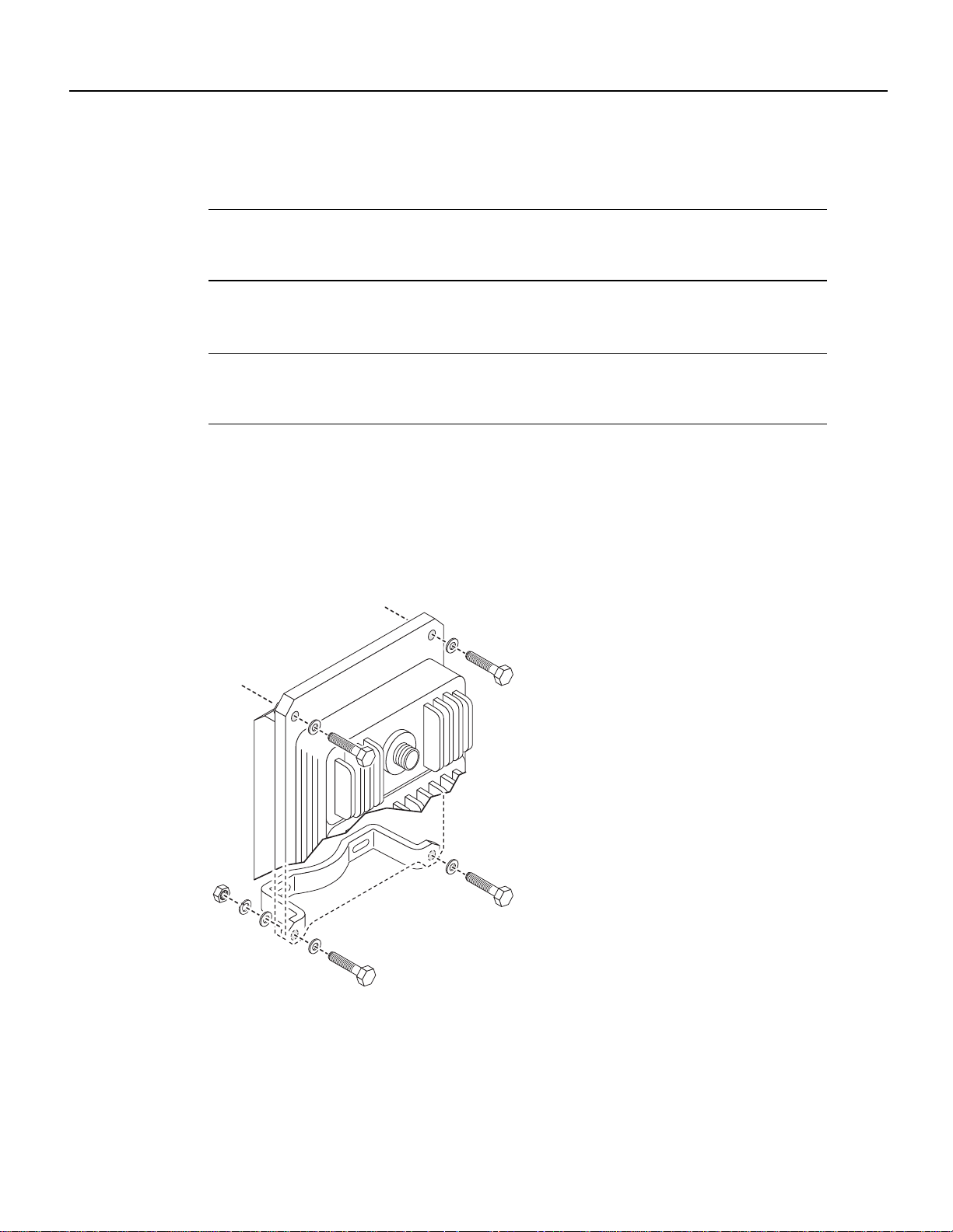
Step 1 Attach one mounting bracket to the lower portion of the wireless transverter. (See
Figure 37.)
Step 2 Threadtwohex bolts andwashers through the mountingholes at the topof the transverter.
(See Figure 37.)
Figure 37 Attaching the Lower Mounting Bracket and Upper Bracket Hardware
28996
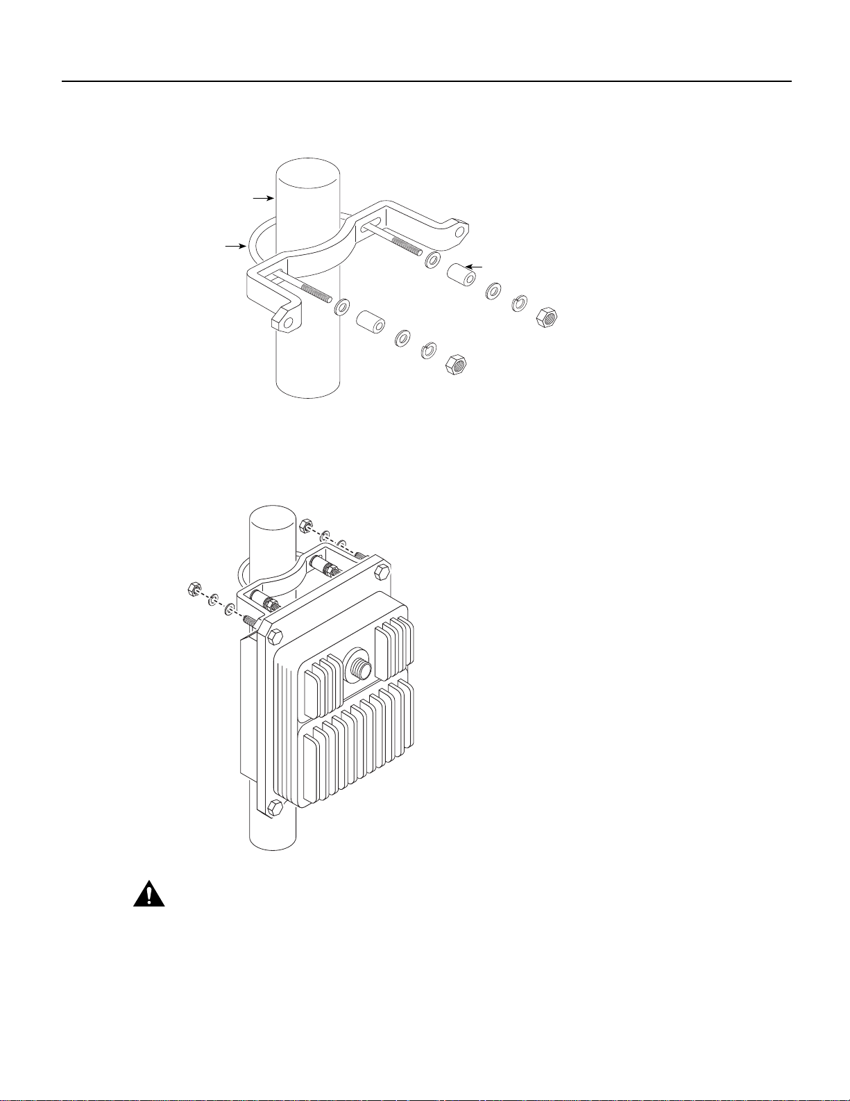
Step 3
34 Cisco uBR7200 Series Universal Broadband Router Wireless Modem Card and Subsystem Installation and Configuration
Select the appropriate size U-bolt fromthemountingkit and attach the remaining bracket
to the antenna mast and tighten the nuts. (See Figure 38.) If necessary, use the provided
spacers. This will be the bracket that mounts to the top of the transverter.
Final Review - Cisco Internal Use Only
Mounting the Wireless Transverter
Figure 38 Attaching the Top Mounting Bracket to the Antenna Mast
Antenna mast
U-bolt
Spacer (optional)
27291
Step 4
Using a 9/16-inch wrench, attach the transverter to the top mounting bracket. (See
Figure 39.)
Figure 39 Attaching the Transverter to the Top Mounting Bracket
27901
Caution
Do not leave the transverter unattended until all the fasteners have been tightened.
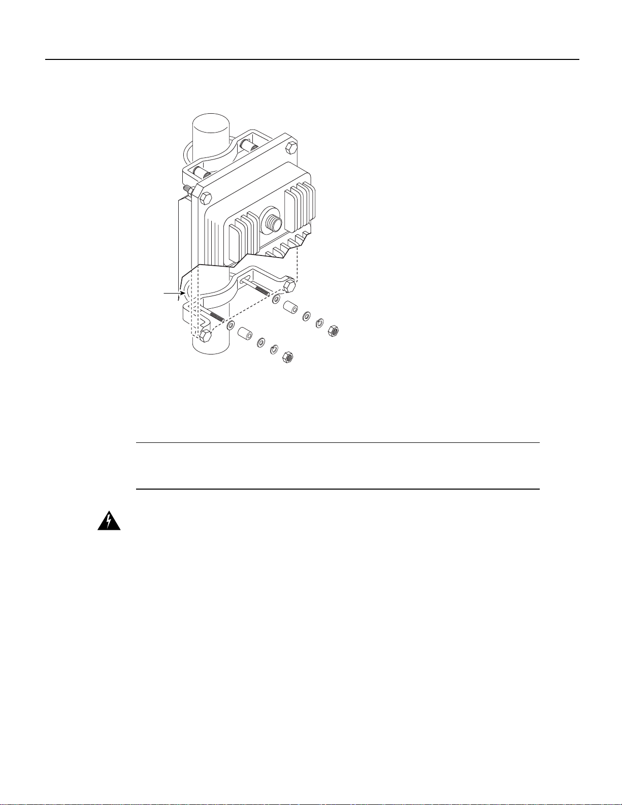
Step 5 Attach the U-bolt to the bottom bracket (see Figure 40), and tighten.
Cisco uBR7200 Series Universal Broadband Router Wireless Modem Card and Subsystem Installation and Configuration 35
Final Review - Cisco Internal Use Only
Installing a Wireless Transverter
Figure 40 Attaching the Bottom U-Bolt
U-bolt
Step 6
Tighten all fasteners to 15 foot pounds of torque.
Cabling the Wireless Transverter
Note These instructions apply to the MMDS transverter manufactured and supplied by Cisco. If
you have purchased a transverter from another vendor, refer to that vendor’s instructions for
installation.
Warning Ensure that the power/breaker switches (on the power feed panel) for both the Main and
Diversity transverter are in the OFF position. (See Figure 22.)
Cables leading to the wireless transverter may require through-bulkhead connectors, lightning
protection, or other accessories. For more detailed information concerning these items, refer to the
Cisco Broadband Fixed Wireless Site Planning Guide.
Attaching the Ground Lug
A ground lug kit is provided with he transverter.Use the following steps to attach the ground lug to
the transverter chassis.
27903
Step 1 Attach an approved ground wire to the ground lug.
Step 2 Locate the two ground lug threaded holes on the lower right mounting bracket of the
transverter chassis.
Step 3 Align the ground lug with the threaded holes and fasten it to the chassis using the two
screws included in the kit. (See Figure 41.)
36 Cisco uBR7200 Series Universal Broadband Router Wireless Modem Card and Subsystem Installation and Configuration
Final Review - Cisco Internal Use Only
Cabling the Wireless Transverter
Figure 41 Attaching the Ground Lug
Ground lug
27295
Step 4
Using a number 2 Phillips screwdriver, tighten the screws.
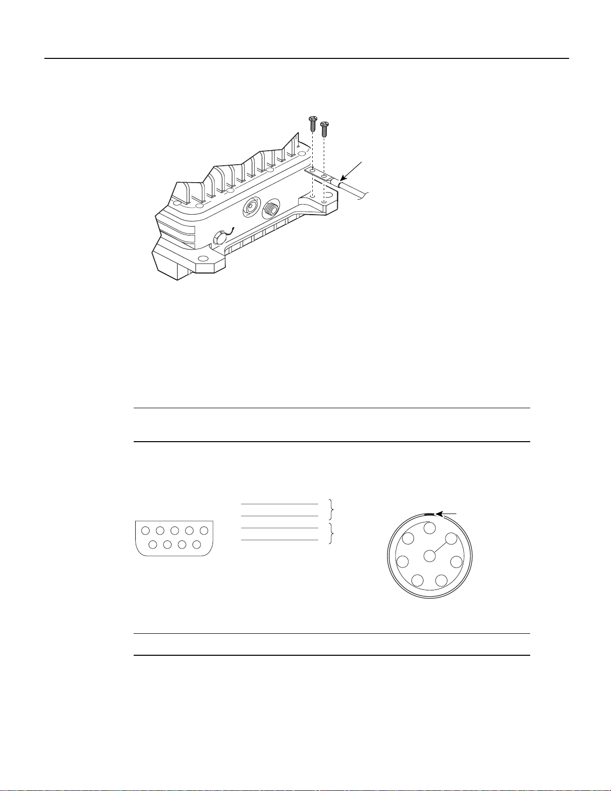
Attaching the LEMO Connector to the Control Cable
An 8-pin LEMO plug designed to be used with a .24-inch or less outside diameter jacket cable with
braided shielding is provided to attach the control cable to the wireless transverter. Using Figure 42
as a guide, use the following instructions to wire the connector to the control cable coming from the
power feed panel.
Note If a cable with a larger outside diameter is used, alternate sealing hardware must be used (not
supplied).
Figure 42 DB-9 to 8-Pin Lemo Wiring
DB-9
DB-9
Male
234
1
6789
Male
1
5
2
3
4
5
6
7
8
9
LEMO 8-pin
plug
1
Twisted pair
2
3
Twisted pair
4
5
6
7
8
LEMO 8-pin plug
(viewed from back
of plug)
1
2
3
4
7
8
6
5
Keyway
27289
Note The cable shield must be grounded to the connector housing.
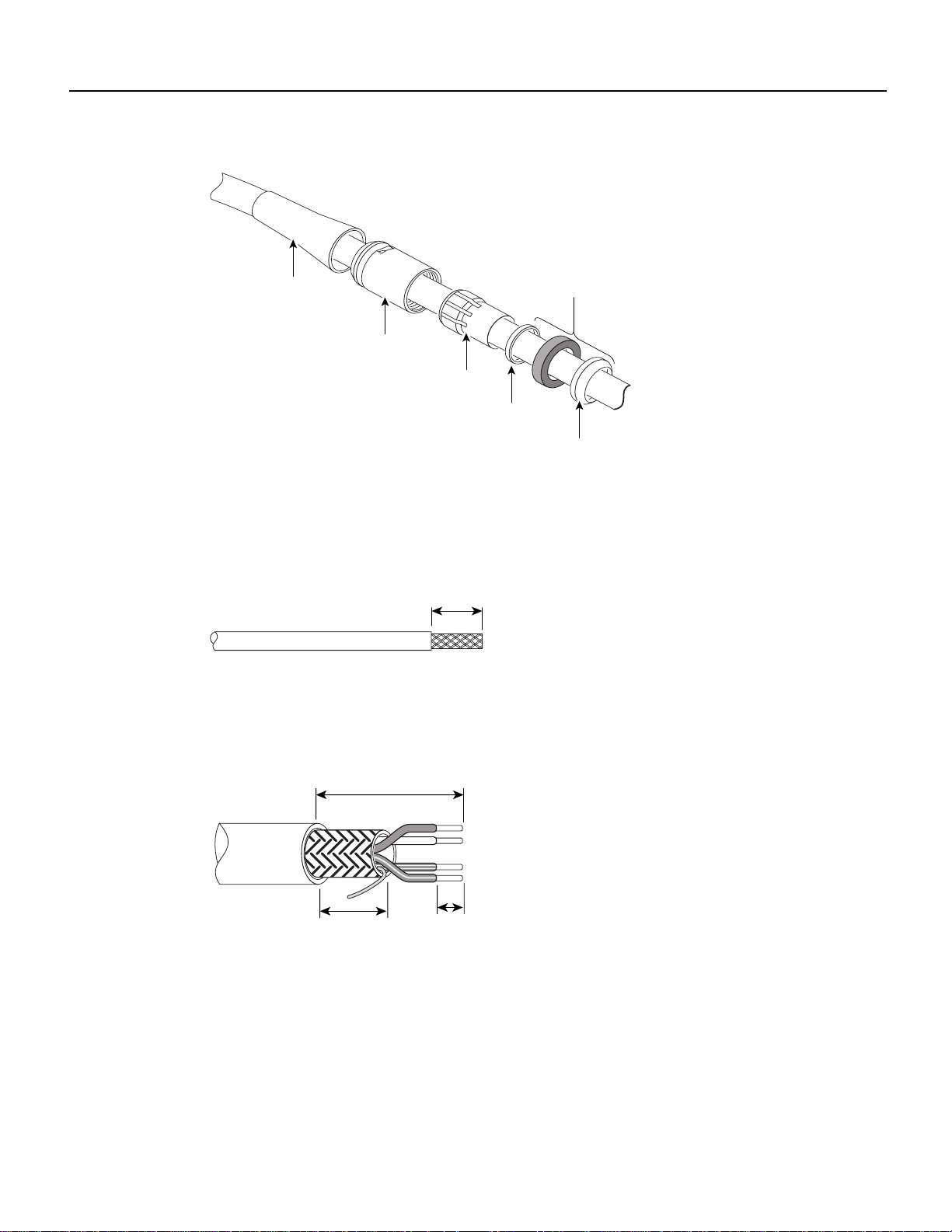
Step 1 Slide the cable relief, collet nut, collet, and sealing hardware onto the cable. (See
Figure 43.)
Cisco uBR7200 Series Universal Broadband Router Wireless Modem Card and Subsystem Installation and Configuration 37
Final Review - Cisco Internal Use Only
Installing a Wireless Transverter
Figure 43 Sliding the Hardware on the Cable
Cable relief
Collet nut
Collet
(Beveled side
away form collet)
Step 1
Strip the cable jacket to expose the shielding. (See Figure 44.)
Figure 44 Stripping the Cable Jacket
0.256 in.
(6.5 mm)
28091
Step 2
Strip the conductor insulation to the dimensions shown in Figure 45.
Figure 45 Striping the Conductor Insulation
Sealing hardware
Earthing
cone
28093
0.256 in.
(6.5 mm)
0.118 in.
(3.0 mm)
28097
Step 3
0.157 in.
(4.0 mm)
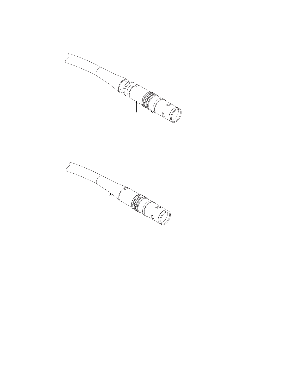
Solder the contacts, then position the midpieces on the insert. (See Figure 46.) Make sure
the insert key appears through the midpiece window.
38 Cisco uBR7200 Series Universal Broadband Router Wireless Modem Card and Subsystem Installation and Configuration

Final Review - Cisco Internal Use Only
Cabling the Wireless Transverter
Figure 46 Positioning the Midpieces
Sealing hardware
Collet nut
Insert
Collet
carrier
Insert
28094
Step 4
Insert
carrier
Position the collet and sealing hardware. (See Figure 47.) Trim the foil and plastic inner
foil. Fold the ground wire over the earthing cone, making sure not to exceed the beveled
edge.
Figure 47 Positioning the Collet and Sealing Hardware
28095
Step 5
Line up the key on the insert carrier with the notch in the housing. Install the outer shell
and tighten the collet nut to 5 inch-pounds of torque using a plug securing wrench over
the nozzle and a torque wrench on the collet nut. (See Figure 48.)
Cisco uBR7200 Series Universal Broadband Router Wireless Modem Card and Subsystem Installation and Configuration 39
Final Review - Cisco Internal Use Only
Installing a Wireless Transverter
Figure 48 Tightening the Collet Nut
Collet nut
Outer shell
28096
Step 6
Figure 49 Cable Relief Attached to Collet Nut
Connecting the Control Cable
Connect the control cable from the power feed panel port marked Main/ODU to the Control
connector on the Main transverter. (See Figure 50.)
To complete the assembly, attach the cable relief to the back nut on the collet nut. (See
Figure 49.)
Cable relief
28092
40 Cisco uBR7200 Series Universal Broadband Router Wireless Modem Card and Subsystem Installation and Configuration

Final Review - Cisco Internal Use Only
Cabling the Wireless Transverter
Figure 50 Connecting the Control Cable
28543
If the diversity feature is being used, connect the control cable from the power feed panel port
marked Diversity/ODU to the Control connector on the diversity transverter.
Connecting the IF Cable
Connect the IF cable from the power feed panel port marked Main-ODU/Output to the IF Input
connector on the main transverter. (See Figure 51.) Tighten the connection with an adjustable
wrench or pliers.
Figure 51 Connecting the IF Cable
If the diversity feature is being used, connect the IF cable from the power feed panel port marked
Diversity-ODU/Output to the IF Input connector on the diversity transverter, and tighten with an
adjustable wrench or pliers.
28544
Connecting the Antenna Cable
Connect the RF cable leading to the Main antenna to the N-type connector on the duplexer on the
main transverter. (See Figure 52.)
Cisco uBR7200 Series Universal Broadband Router Wireless Modem Card and Subsystem Installation and Configuration 41

Final Review - Cisco Internal Use Only
Configuring a Wireless Modem Card
Figure 52 Connecting the Antenna Cable
If the diversity feature is being used, connect the RF cable leading to the diversity antenna to the
N-type connector on the duplexer on the diversity transverter.
This completes the procedure for installing and cabling a wireless transverter. Consult the
instructions provided by your antenna manufacturer for additional instructions on cabling antennas.
28545
Warning After cabling, reinstate power to the power feed panel.
Warning After reinstating the DC power, remove the tape from the circuit breaker switch handle
and reinstate power by moving the handle of the circuit breaker to the ON position.
Configuring a Wireless Modem Card
After you have installed or replaced a wireless modem card and subsystem, use the Cisco IOS
software command-line interface (CLI) to configure the modem card for operation. Initial startup
requirements and examples, as well as the commands to log in to the router and complete the initial
configuration are described in this section.
Note You must perform a basic configuration of the Cisco uBR7200 series router before
configuring the wireless modem cards. Refer to the Cisco uBR7200 Series Universal Broadband
Router Installation and Configuration Guide publication that shipped with your Cisco uBR7246 or
Cisco uBR7223 for more information.
login
Use the steps in Table 7 to log in to the router and enter the required modes to start the configuration
process.
42 Cisco uBR7200 Series Universal Broadband Router Wireless Modem Card and Subsystem Installation and Configuration
 Loading...