

WJ Communications SA1070 Datasheet
Watkins-Johnson: The Cell Extenders
Power Amplifiers
SA1070
TDMA 8-Watt
1.93 GHz to 1.99 GHz
Linear Power Amplifier Module
The Wireless Edge
™
■
8 Watts TDMA IS-136
■
+38 dBm P1dB
■
40 dB Gain
■
-30°C to +85°C
2.300
GND+25 V+5 V
GND
+25 V+5 V
4x ] .136 THRU
RF IN
RF OUT
MODEL WJ-SA1070
PCS AMPLIFIER
1930-1990 MHz
SERNO-0112
WATKINSJOHNSON
5.00
3.75
3.100
4.700
.150
.150
.75
2X .475
2X SMA FEMALE
OUTLINE DRAWING
Amplifier output spectrum with a +37 dBm (5-watt) NADC π/4
DQPSK output. The first and second adjacent channels are at
30 kHz and 60 kHz offsets. The first adjacent channels of our
measurements do not overlap with the primary channel.
Output modulation characteristics with a +37 dBm (5-watt) NADC
π
/4 DQPSK output. This HP 89441A display includes a constellation
diagram, the samplings of vector error, and the EVM (error vector
magnitude) calculations from averaged samplings of the signal.
W
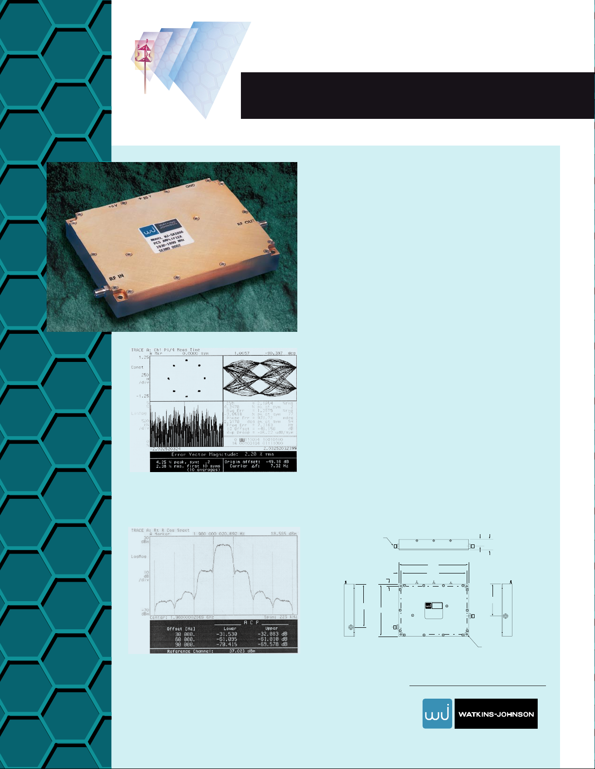
atkins-Johnson’s SA1070 Power
Amplifier provides exceptional lin-
earity and low vector error for TDMA digi-
tal modulation applications. Utilizing WJ’s
GaAs amplifiers driving bipolar transistors
in the class A output stage, the SA1070
achieves a very high output third-order
intercept point combined with superior
efficiency.
WJ Wireless Products: 1-800-WJ1-4401• FAX: 650-813-2447• e-mail: wireless.info@wj.com.
Watkins-Johnson: The Cell Extenders
Power Amplifiers
The Wireless Edge
™
SA1070
TDMA 8-Watt 1.93 GHz to 1.99 GHz
Linear Power Amplifier Module
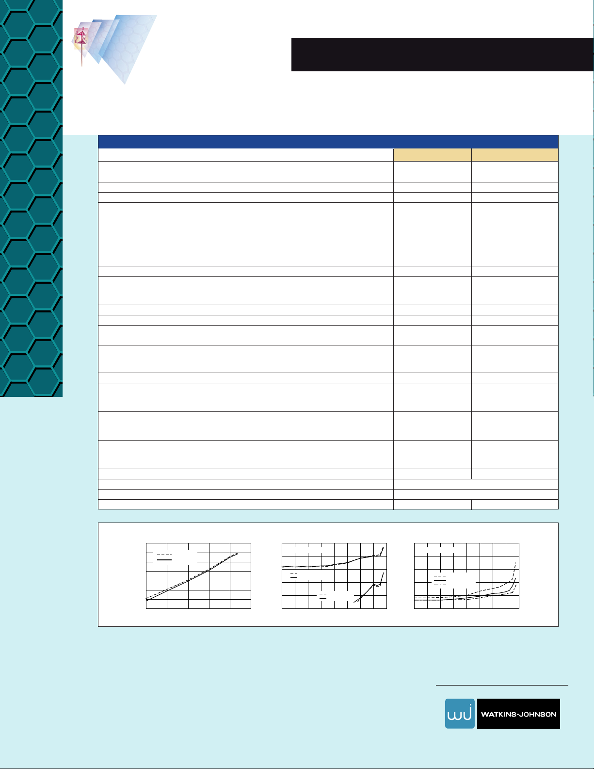
IM (Lower)
IM (Upper)
15
-80
-70
-60
-50
-40
-30
-20
-10
20 25
Output Power Per CW Tone (dBm)
Intermod Product Rejection (dBc)
30 35 40 25
-70
-60
-50
-40
-30
-20
2927 31 33 35 37
Output Power (dBm)
Adjacent Channel Power Rejection (dB)
39 41
ACPR at -30 KHz
ACPR at +30 KHz
ACPR at -60 KHz
ACPR at +60 KHz
Intermodulation Suppression vs. Output
Power Per Tone
ACP Rejection vs. Output Power
25
-1
1
3
5
7
9
2927 31 33 35 37
Output Power (dBm)
EVM (%) and Phase Error (degree)
39 41
EVM vs.Output Power
EVM
Mag Error (%)
Phase Error (deg)
NADC TDMA Format NADC TDMA Format
Specifications
Parameters Typical Level Specified Limits
Frequency 1.930 -1.990 GHz
P
out
at 1 dB Gain Compression (Min.) +38 dBm +37 dBm
Small Signal Gain at +25°C 40±0.75 dB
Gain Variation over Temperature (-30° to +85°C) ±0.75 dB
NADC Parameters1(with P
out
≥39 dBm)
Output Power +39 dBm +39 dBm
ACP (30 kHz offset) -29 dBc -26 dBc
ACP (60 kHz offset) -51 dBc -45 dBc
Error Vector Magnitude 2.9% 4.0%
Magnitude Error 1.7% 2.5%
Phase Error 1.3 degrees 1.7 degrees
3rd Order Two-Tone Output Intercept Point, Measured with +25 dBm per Tone, T = 25°C (Min.) +47 dBm +45 dBm
Harmonic Output (with +39 dBm TDMA output at the fundamental) (Max.)
2nd Harmonic -25 dBm -13 dBm
3rd Harmonic -17 dBm -13 dBm
Noise Figure (Max.) 5.0 dB 6.0 dB
Input and Output Impedance 50 ohm
Return Loss, 1.930 to 1.990 GHz (Min.)
Input and Output -20 dB -15 dB
Load Mismatch Sustainable without Damage (Pin ≤ -5 dBm Vsupply ≤ +25.0 Vdc) 3.0:1
Stability, no Spurious Output above -50 dBm Unconditionally stable
for all loads
Supply Voltages +5 and +25 Vdc
Maximum Supply without Damage
+25 Volt Supply +26.5 Vdc
+5 Volt Supply +6 Vdc
Maximum DC Current
+25 Vdc Supply 1850 mA 2000 mA
+5 Vdc Supply 505 mA 560 mA
DC Power Dissipation (Max.)
+25 Vdc Supply 50 watts
+5 Vdc Supply 2.8 watts
Baseplate Temperature Range
2
-30 to +85°C
Size (Refer to interface control drawing WJ-299010SK) 0.75” (H) 3.75” (W) 5.00” (L)
RF Connectors SMA Female
Weight 13.8 oz. 14 oz.
Notes: 1. TDMA spectral regrowth is measured with a spread spectrum input from a Marconi 2051 Signal Generator selecting the “Digital/Cellaular/NADC”
modulation system that produces
π
/4 DQPSK modulation with 24.30 kHz symbol rate and Root Nyquist filtering with alpha = 0.35.
This unit is to be mounted on a ground plane and thermal heat sink, with a maximum heat sink temperature of +85°C.
2. This unit is to be mounted on a thermal heat sink with a maximum heatsink temperature of +85°C.
WATKINS-JOHNSON COMPANY• 3333 Hillview Avenue • Palo Alto, CA 94304-1223
 Loading...