


W
Watkins-Johnson Company
Repeater
Manual
WATKINS-JOHNSON COMPANY
3333 Hillview Avenue
Palo Alto, CA 94304-1223

Watkins-Johnson Company
PCS Repeater
Manual
“This drawing, print, or document and subject matter disclosed
herein are proprietary items to which Watkins-Johnson Company
retains the exclusive right of dissemination, reproduction,
manufacture and sale. This drawing, print or document is
submitted in confidence for consideration by the designated
recipient or intended using organization alone unless permission
for further disclosure is expressly granted in writing.”
09/99
WATKINS-JOHNSON COMPANY
3333 Hillview Avenue
Palo Alto, CA 94304-1223
(800) 951-4401
Internet: http://www.wj.com

Repeater Table of Contents
Table of Contents
Section Topic Page
Chapter 1 General Information and Safety Precautions 1-1
Introduction 1-1
Specifications 1-6
Safety Considerations 1-10
Description 1-10
Mechanical 1-11
Environmental Conditions 1-12
Chapter 2 Installation 2-1
Introduction 2-1
Unpacking and Inspection 2-1
Preparation For Use 2-1
Pre-Installation Information 2-2
Installation Information 2-3
Repeater Initial Turn-On Procedure 2-6
Setup 2-6
Isolation and Alignment Procedure 2-7
Multicarrier & FCC Spurious 2-9
Connectors 2-10
Storage 2-11
Packing for Reshipment or Storage 2-11
Chapter 3 Operation 3-1
Introduction 3-1
Operating Instructions 3-1
Chapter 4 Scheduled Maintenance 4-1
Introduction 4-1
Scheduled Maintenance Action Index 4-1
Equipment Required 4-1
Preventive Maintenance Procedures 4-1
General Maintenance 4-2
Alignment 4-2
Repair 4-2
Chapter 5 Drawings 5-1
R1910 Mounting 5-1
R1920 Mounting Plate 5-2
R1920 and BB42 Mounting 5-3
R1920 Electrical and System Configuration 5-4
i

Repeater General Information and Safety Precautions
CHAPTER 1
GENERAL INFORMATION AND SAFETY PRECAUTIONS
1-1 INTRODUCTION
This manual provides information pertaining to the installation, operation, and maintenance of the
Watkins-Johnson Repeaters, shown in Figure 1-1. The model number represents the type of repeater.
This manual covers the following types of repeaters. The model numbers and letters are defined in
the following example.
Example: R1910CAD-1M is a PCS indoor repeater, with CDMA modulation, using frequency
bands A and D, 1.25mhz bandwidth, with a modem.
Repeater Model Number Repeater Description
R1910 PCS Inbuilding Repeater
R1920 PCS High Power Repeater
R1930 PCS Medium Power Repeater
R1940 PCS Low Power Repeater
R810 Cellular Inbuilding Repeater
R820 Cellular High Power Repeater
Modulation PCS
Frequency
CDMA = C
TDMA = T
GSM = G
AD*
BE*
FC*
Band
Bandwidth Interface
Option
-1 = 1.25 MHz
-2 = 0.20 MHz
-3 = 5.00 MHz
-4 = 15.0 MHz
-5 = 1.00 MHz
-6 = 4.50 MHz
-7 = 7.00 MHz
M= modem
* Specifies dual bands.
** The R810 and R820 cover the entire A or B band
1-1

Repeater General Information and Safety Precautions
This manual is divided into five chapters, the first four covering a particular topic for the operation
and maintenance of the unit. Chapter 5 includes drawings to assist in mounting WJ repeaters. The
topics are as follows:
Chapter Topic
1 General Information and Safety Precautions
2 Installation
3 Operation
4 Scheduled Maintenance
5 Drawings
1-2

Repeater General Information and Safety Precautions
Figure 1-1. R1910 and R810 Repeater
1-3
Repeater General Information and Safety Precautions
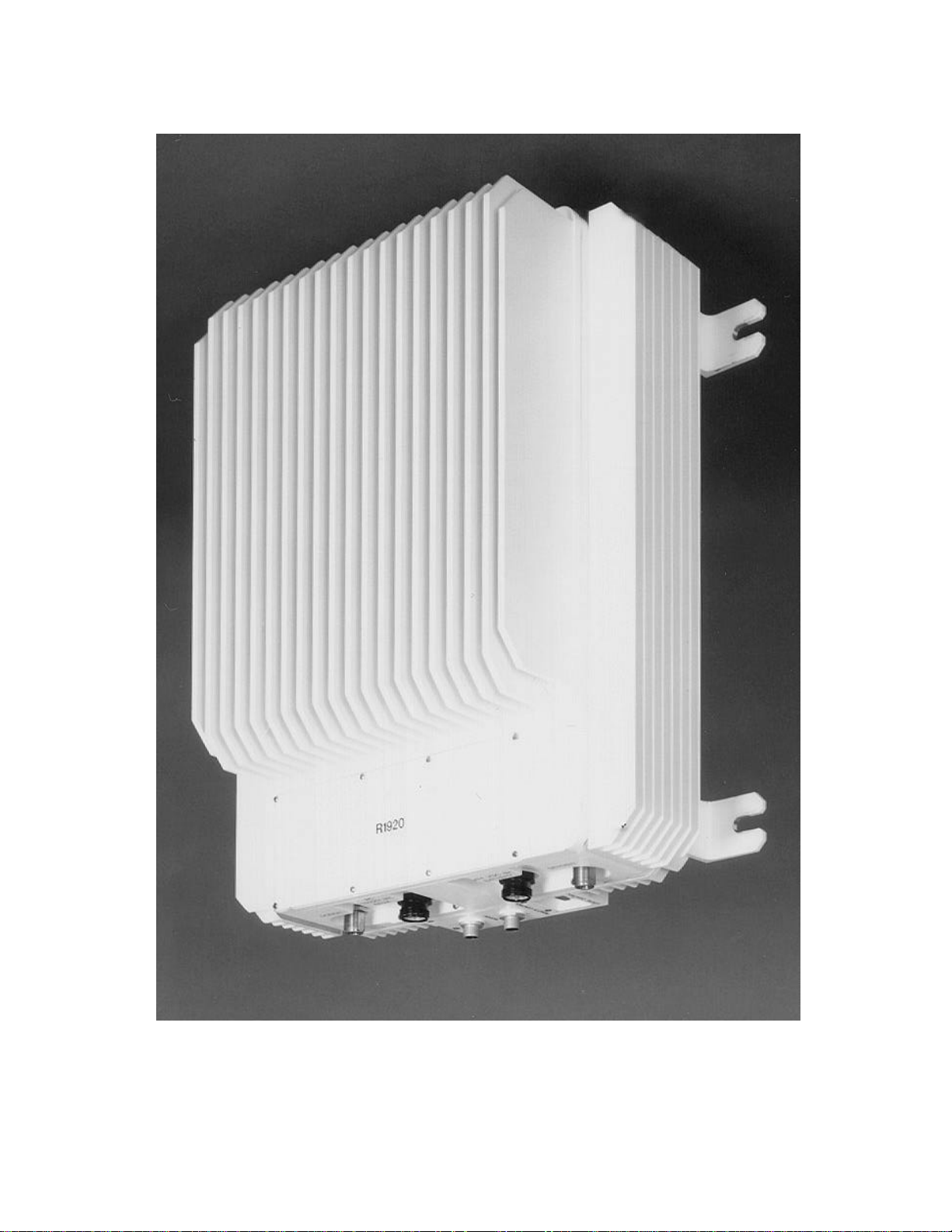
Figure 1-2. R1920/30/40, R820 Repeater
1-4

Repeater General Information and Safety Precautions
Chapter 1 provides a general description of the Repeater and summarizes the electrical, mechanical,
and environmental characteristics. It also provides a tabular listing of the Repeater performance
specifications. Safety precautions to be observed while operating or servicing the unit are also
explained.
Chapter 2 provides instructions for the initial inspection and installation of the Repeater. It describes
the purpose and function of all I/O connectors, provides initial start-up instructions, and provides
installation verification tests.
Chapter 3 describes the purpose and function of all remote controls and status indicators and
explains how to operate the unit.
Chapter 4 provides a scheduled maintenance action index and describes maintenance procedures that
should be performed on a regular basis, such as cleaning and inspection.
Chapter 5 provides drawings useful when mounting a WJ repeater to a structure.
1-5

Repeater General Information and Safety Precautions
1-2 SPECIFICATIONS
Table 1-1. R1910 Specification
DESCRIPTION SPECIFICATION
Frequency Band AD, BE, or FC
Output Power 100 mWatts CDMA
500 mWatts TDMA
500 mWatts PCS-1900 (GSM)
Filter Bandwidth 1.25 MHz CDMA (other filters available)
200KHz TDMA (other filters available)
200 kHz GSM-1900 (other filters available)
Noise Figure 4 dB Typical
Maximum Input without damage -10 dBm
Input Impedance 50 ohms
Gain Range 40 dB to 70 dB or 65 dB to 95 dB
Gain Steps 2 dB
Signal Delay 5 usec max
Power 115 / 230 VAC, 60 / 50 Hz, 1.6 / 0.8 Amps
Alarms & Status Synthesizer, Amplifiers, Power Amplifier, Output Power, Oscillation
Interface RS-232 (modem optional)
Control Gain, Channel frequency, Auto Level Control, and Tracking Offset
Cooling Convection
Temperature Operating: -10 to +45ºC
Storage: -40 to +85ºC
Size 12” x 16” x 3”
Weight 19 lbs.
Weather Resistance NEMA 12
Connectors
RF
Control
AC Power
Type N
9 pin Dsub Female
NEMA Type 5-ISP
1-6

Repeater General Information and Safety Precautions
Table 1-2. R1920 Specification
DESCRIPTION SPECIFICATION
Frequency Band AD, BE, or FC
Output Power 8 Watts CDMA
10 Watts TDMA
15 Watts GSM-1900
Filter Bandwidth 1.25 MHz CDMA (other filters available)
200 kHz TDMA (other filters available)
200 kHz GSM-1900 (other filters available)
Noise Figure 4 dB Typical
Maximum Input without damage -10 dBm
Input Impedance 50 ohms
Gain Range 65 dB to 95 dB
Gain Steps 2 dB
Signal Delay 5 usec max
Power 115 / 230 VAC, 60 / 50 Hz, 4 / 2 Amps
Alarms & Status Synthesizer, Amplifiers, Power Amplifier, Output Power, Oscillation
Interface RS-232 and modem
Control Gain, Channel frequency, Auto Level Control, and Tracking Offset
Cooling Convection
Temperature Operating: -40 to +50ºC
Storage: -40 to +85ºC
Size 14.5” x 16” x 9”
Weight 55 lbs.
Weather Resistance NEMA 4X
Connectors
RF
Control
AC Power
Battery
Type N
9 pin D-sub, 3 pin circular(see section 2 for pinout information)
3 pin Mini-circular(see section 2 for pinout information)
6 pin Mini-circular
1-7

Repeater General Information and Safety Precautions
Table 1-3. R1930 Specification
DESCRIPTION SPECIFICATION
Frequency Band AD, BE, or FC
Output Power 4 Watts CDMA
Filter Bandwidth 1.25 MHz CDMA (other filters available)
Noise Figure 4 dB Typical
Maximum Input without damage -10 dBm
Input Impedance 50 ohms
Gain Range 65 dB to 95 dB
Gain Steps 2 dB
Signal Delay 5 usec max
Power 115 / 230 VAC, 60 / 50 Hz, 4 / 2 Amps
Alarms & Status Synthesizer, Amplifiers, Power Amplifier, Output Power, Oscillation
Interface RS-232 and modem
Control Gain, Channel frequency, Auto Level Control, and Tracking Offset
Cooling Convection
Temperature Operating: -40 to +50ºC
Storage: -40 to +85ºC
Size 14.5” x 16” x 9”
Weight 55 lbs.
Weather Resistance NEMA 4X
Connectors
RF
Control
AC Power
Battery
Type N
9 pin D-sub, 3 pin circular(see section 2 for pinout information)
3 pin Mini-circular(see section 2 for pinout information)
6 pin Mini-circular
1-8

Repeater General Information and Safety Precautions
Table 1-4. R1940 Specification
DESCRIPTION SPECIFICATION
Frequency Band AD, BE, or FC
Output Power 2 Watts CDMA
Filter Bandwidth 1.25 MHz CDMA (other filters available)
Noise Figure 4 dB Typical
Maximum Input without damage -10 dBm
Input Impedance 50 ohms
Gain Range 65 dB to 95 dB
Gain Steps 2 dB
Signal Delay 5 usec max
Power 115 / 230 VAC, 60 / 50 Hz, 4 / 2 Amps
Alarms & Status Synthesizer, Amplifiers, Power Amplifier, Output Power, Oscillation
Interface RS-232 and modem
Control Gain, Channel frequency, Auto Level Control, and Tracking Offset
Cooling Convection
Temperature Operating: -40 to +50ºC
Storage: -40 to +85ºC
Size 14.5” x 16” x 9”
Weight 55 lbs.
Weather Resistance NEMA 4X
Connectors
RF
Control
AC Power
Battery
Type N
9 pin D-sub, 3 pin circular(see section 2 for pinout information)
3 pin Mini-circular(see section 2 for pinout information)
6 pin Mini-circular
1-9

Repeater General Information and Safety Precautions
Table 1-1. R810 Specification
DESCRIPTION SPECIFICATION
Frequency Band A or B
Output Power 100 mWatts
Filter Bandwidth Entire A or B band
Noise Figure 4 dB Typical
Maximum Input without damage -10 dBm
Input Impedance 50 ohms
Gain Range 40 dB to 70 dB
Gain Steps 2 dB
Signal Delay 5 usec max
Power 115 / 230 VAC, 60 / 50 Hz, 1.6 / 0.8 Amps
Alarms & Status Synthesizer, Amplifiers, Power Amplifier, Output Power, Oscillation
Interface RS-232 (modem optional)
Control Gain, Channel frequency, Auto Level Control, and Tracking Offset
Cooling Convection
Temperature Operating: -10 to +45ºC
Storage: -40 to +85ºC
Size 12” x 16” x 4”
Weight 19 lbs.
Weather Resistance NEMA 12
Connectors
RF
Control
AC Power
Type N
9 pin Dsub Female
NEMA Type 5-ISP
1-10

Repeater General Information and Safety Precautions
Table 1-1. R820 Specification
DESCRIPTION SPECIFICATION
Frequency Band A or B
Output Power 5 Watts
Filter Bandwidth Entire A or B band
Noise Figure 4 dB Typical
Maximum Input without damage -10 dBm
Input Impedance 50 ohms
Gain Range 55 dB to 85 dB
Gain Steps 2 dB
Signal Delay 5 usec max
Power 115 / 230 VAC, 60 / 50 Hz, 4 / 2 Amps
Alarms & Status Synthesizer, Amplifiers, Power Amplifier, Output Power, Oscillation
Interface RS-232 (modem optional)
Control Gain, Channel frequency, Auto Level Control, and Tracking Offset
Cooling Convection
Temperature Operating: -10 to +45ºC
Storage: -40 to +85ºC
Size 14.5” x 16” x 10”
Weight 55 lbs.
Weather Resistance NEMA 12
Connectors
RF
Control
AC Power
Battery
Type N
9 pin D-sub, 3 pin circular(see section 2 for pinout information)
3 pin Mini-circular(see section 2 for pinout information)
6 pin Mini-circular
1-11

Repeater General Information and Safety Precautions
NOTE:
This equipment has been tested and found to comply with the
limits for a Class A digital device, pursuant to Part 15 of the FCC
Rules. These limits are designed to provide reasonable protection
against harmful interference when the equipment is operated in a
commercial environment. This equipment generates, uses, and
can radiate radio frequency energy and, if not installed and used
in accordance with the instruction manual, may cause harmful
interference to radio communications. Operation of this
equipment in a residential area is likely to cause harmful
interference in which case the user will be required to correct the
interference at his own expense.
__________
CAUTION:
Changes or modifications not expressly approved by the
manufacturer responsible for compliance could void user’s
authority to operate the equipment.
1-3 SAFETY CONSIDERATIONS
__________
WARNING
To prevent personal injury, observe all safety precautions and
warnings stated on the instrument and in this manual.
Specific warnings, cautions, and instructions are placed wherever applicable throughout this manual.
These precautions must be observed during all phases of operation, service, and repair of this unit.
Failure to comply with these precautions or with specific warnings elsewhere in this manual violates
safety standard of design, manufacture, and intended use of this instrument.
1-4 DESCRIPTION
The WJ-R19XX Repeaters are used to extend the coverage of a PCS basestation. For example,
inside buildings that do not allow sufficient signal strength from the basestation, there exists a hole in
the coverage for wireless service. The WJ-R1910 is designed to solve that problem.
Likewise, tall buildings in a metropolitan area, or mountains in a more rural area, can reduce
basestation signal strength such that pockets of unusable areas develop. The WJ-R1920/30/40 is
designed to solve that problem.
1-12

Repeater General Information and Safety Precautions
RepeaterRepeaterRepeaterRepeater
Server Antenna
Donor Antenna
WJ R1910
The repeater receives the basestation signal via an external antenna see Figure 1-3. This signal is
amplified and filtered by the repeater and ultimately retransmitted via a second antenna. The entire
process is duplicated for the reverse path where the handset signal is amplified and filtered and
retransmitted to the basestation. This technique provides PCS coverage inside buildings or in
outside areas that previously did not have sufficient signal strength.
Outside Building Inside Building
Lightning Arrestor
Figure 1-3. R1910/R810 Typical Usage
1-4.1 Remote Control
Remote control and status reporting of the repeater is provided either through an RS-232 serial
interface or via modem using a standard POTS line. Either interface permits the control of channel
frequency and gain, and can provide unit alarm status.
1-4.2 Prime Power
The R1910 and R810 is equipped with a power supply with an input of 115 / 230 VAC, 60 / 50 Hz,
1.6 / 0.8 Amps. Power consumption is approximately 65 Watts.
The R1920/30/40 and R820 is equipped with a power supply with an input of 115 / 230 VAC, 60 /
50 Hz, 4 / 2 Amps with an optional +24VDC/Battery input. Power consumption is approximately
250 Watts.
1-5 MECHANICAL
The R1910 and R810 are a 12 x 16 x 3 wall mount unit. Four mounting feet are provided for
installation. The unit is designed to withstand a NEMA 12 type environment.
1-13

Repeater General Information and Safety Precautions
The R1920/30/40 and R820 a 12 x 16 x 3 tower mount unit. A mounting bracket is provided for
installation. The unit is designed to withstand a NEMA 4X type environment.
1-6 ENVIRONMENTAL CONDITIONS
1-6.1 Non-operating Environmental Conditions
The Repeater will survive strains, jars, vibrations, or other conditions incident to normal
maintenance, transportation, and handling. Temperature ranges can vary between -40°C and
+85°C with humidity up to 95% non-condensing.
1-6.2 Operating Environmental Conditions
The R1910 and R810 can be installed and operated in a commercial environment with temperatures
varying between -10°C and 45°C.
The R1920/30/40 and R820 can be installed and operated in an outdoor environment with
temperatures varying between -40°C and 50°C.
1-6.3 Transportability
The Repeater can be transported by commercial land carriers or pressurized commercial air carriers
without special handling provisions.
1-14

Repeater Installation
CHAPTER 2
INSTALLATION
2-1 INTRODUCTION
This chapter provides information for the installation, setup and alignment of the R19X0 PCS
Repeater. The information consists of procedures for unpacking, inspection, and preparation for
reshipment or storage, and description of unit connectors. It also provides initial start-up
instructions and installation verification tests.
2-2 UNPACKING AND INSPECTION
Examine the shipping carton for damage before unpacking the unit. If the shipping carton is
damaged, try to have the carrier's agent present when the equipment is unpacked. If carrier's agent is
not available, retain the shipping cartons and padding material for the carrier's inspection if damage
to the equipment is evident after it has been unpacked.
Verify that the equipment is complete, as listed on the packing slip. Contact Watkins-Johnson
Company, Palo Alto, California, or your local Watkins-Johnson representative with details of any
shortage.
The unit was thoroughly inspected and factory adjusted for optimum performance prior to shipment.
Thus, it is ready for use upon receipt. After unpacking and checking contents against the packing
slip, visually inspect all exterior surfaces for dents and scratches. If external damage is visible,
contact Watkins-Johnson Company.
2-3 PREPARATION FOR USE
2-3.1 Power Requirements
The R1910 is equipped with a power supply that accepts 115 / 230 VAC 1.6 / 0.8 Amps @ 60 /
50 Hz single phase. Power consumption of the R1910 is approximately 65 Watts. The R1920/30/40
is equipped with a power supply that accepts 115/230 VAC 4 / 2 Amps @ 50/60 Hz, with optional
+24VDC/Battery input. Power consumption is approximately 250 Watts.
___________
WARNING
Removing or defeating the ground prong on the power cord may
present a lethal shock hazard. Do not use an ac two-to-three wire
adapter plug with this unit.
The R1910 power cord has a 3-conductor grounded plug complying with the National Electric Code
(NEMA Type 5-15P) for 110 VAC operation. For the R1920/30/40, or for operation at other
voltages, contact Watkins-Johnson Company or a qualified service technician.
2-1

Repeater Installation
2-3.2 Software Installation
The repeater control application provided on 3.5” floppy disks or CD-ROM, runs on any Personal
Computer (PC) running Microsoft Windows 95, 98, or NT 4.0 or higher. The computer must also
have one of two serial communications ports available for use, COM 1 or COM 2. To install the
application, insert disk 1 into floppy disk drive A: and from the Start menu select Run and enter
“a:\setup” in the text box of the Run window. Click the OK button and follow the instructions given.
2-3.3 Operating Environment
Environmental conditions during operation should normally be limited as follows:
R1910:
a. Maximum humidity: 95%
b. Temperature range: -10°C to +45°C.
R1920/30/40:
a. Temperature range: -40°C to +50°C.
2-4 PRE-INSTALLATION INFORMATION
2-4.1 R1910
You will need to know some basic information before beginning the R1910 installation. Write this
information down, you will need it later on.
1. Base station location and Channel number to be repeated.
2. Reverse Tracking offset in dB (Optional).
3. Location where the Donor antenna is to be installed.
4. Location where the Server antenna is to be installed.
5. Phone number of modem line. (Optional)
6. Location where the R1910 is to be installed (Lat/Long).
2-4.2 R1920/30/40
You will need to know some basic information before beginning the R1920/30/40 installation. Write
this information down, you will need it later on.
1. Base station location and Channel number to be repeated.
2. Reverse Tracking offset in dB (Optional).
3. Location where the Donor antenna is to be installed.
4. Location where the Server antenna is to be installed.
5 Phone number of modem line.
6. Location where the R1920 is to be installed (Lat/Long).
2-5 INSTALLATION INFORMATION
2-2

Repeater Installation
2-5.1 Donor Antenna Installation
The Donor antenna will be mounted outside. The antenna should be installed so that it is in line-ofsight of the base station and is pointed directly at it. If there is an arrow or polarity marking indicated
on the antenna, ensure that it is pointing up. Be sure that the antenna or mast is properly grounded
with a grounding strap. For clearances, grounding and mounting requirements please refer to Article
810 of NEC handbook.
For the R1910, determine where the RF cable will enter building and drill hole if necessary. A
lightning suppressor is highly recommended. Install suppressor inside building where cable entry is.
Attach grounding strap to lightning suppressor. Measure distance between antenna connection and
lightning suppressor. Be sure to add some length for drip loop and cut cable. When routing cable, be
careful not to kink, cut or damage cable. Install connectors on cable using the appropriate tool and
connect to antenna and lightning suppressor connector labeled “Surge”.
2-5.2 Server Antenna Installation
The Server antenna should be located in an open area free from metallic obstruction if possible and in
a location such that mobiles will always be at least 2 meters away. Mount antenna and route cable
from antenna to R1910 location. When routing cable, be careful not to kink, cut or damage cable. No
lightning suppression is needed if the antenna is indoors or under an overhang. Install connector using
the appropriate tool and connect to antenna. For clearances, grounding and mounting requirements
please refer to Article 810 of NEC handbook.
2-5.3 Proper Weather Sealing of RF Connectors.
It is important to properly weather-seal mated connectors against water migration into the RF
connectors and coaxial cables. Water migration into the jumper cable will cause considerable signal
attenuation and poor return loss. There are several commercial products available for this purpose.
The following guidelines should be followed when weather sealing antennas:
• Make sure the connector and cable to be sealed are clean and dry.
• Wrap the sealant to ensure a continuous seal around the connector body and the coaxial cable. If
you pre-wrap the connection with vinyl tape, be careful to leave extra space for the sealant to
contact the connector body and the cable directly.
• After the entire connection has been covered with the manufacturer's recommended amount of
sealant, mold and form the sealant by hand to ensure good contact and to force out trapped air.
• Carefully inspect the seal to make certain that all joints and openings are covered and sealed.
• Wrap the sealant with UV stabilized vinyl tape for additional protection.
2-5.4 R1910 Installation
2-3

Repeater Installation
Ambient temperature in the area where the unit is installed should not exceed 45°C. Be sure that unit
is positioned upright to permit adequate air flow and that nearby equipment does not discharge hot
air directly on the unit. The installation should allow a free flow of air around the outer surfaces of
the chassis. Access to the bottom should be allowed so that input and output connections can be
conveniently made or changed if desired. The unit weighs 19 pounds and may safely be carried and
installed by a single person.
The preferred mounting of the R1910 is on 16” center studs. See mounting bracket installation at end
of manual. If mounting to other surfaces, be sure to use appropriate hardware able to carry 19 lbs.
Before mounting to wall, verify AC power outlet is within 10 feet. Attach the mounting brackets to the
repeater. Screw in the bottom two ¼” X 1 1/2” bolts into studs. Slide in repeater and mark top two
bolt locations. Remove repeater and install remaining two bolts. Slide in repeater and tighten bolts.
Route cable between repeater and lightning suppressor. When routing cable, be careful not to kink,
cut or damage cable. Install connectors using the appropriate tool and connect to lightning suppressor
connector labeled “Protected” and repeater connector J3 Donor. Install connector on cable from
Server antenna and connect to repeater connector J4 Server. Connect power cord.
2-5.5 R1920/30/40 Installation
First verify that the repeater to be installed is within 10 ft of A/C power and POTS line junction box.
The maximum current rating of the branch circuit should be 20Amps. Install mounting plate 450420
to 2 pieces of channel mounted horizontally to tower, using 4 3/8” bolts. If installing optional
battery backup, attach two 12” pieces of channel vertically to horizontal channel directly behind
450420 mounting plate. Attach S-218 shelf to each 12” channel after mounting plate is securely
fastened. Mount repeater to mounting plate and secure using provided bolts. A 12-ft A/C power
cord and modem cable are also supplied with the repeater.
2-5.5.1Cable Wiring information
The R1920/30/40 is shipped with 2 cables that have flying leads at one end. Below is the pinout for
those cable assemblies.
Label Signal Name and Pinout
AC Power Cable 1- Ground(Green)
2- Line(Black)
3- Neutral(White)
Modem Cable 1- Ground(Green)
2- Tip(Red/Black)
3- Ring(Red/White)
2-4

Repeater Installation
WJ #
Connects to:
Cable Description
Manufacturer
MFG #
860000-
AC
3 Pin Mini-Change
Brad Harrison
40903
860000-
Battery
6-Pin Mini-Change
Brad Harrison
41621
860000-
Modem
3-Pin Micro-Change
Brad Harrison
703000D02F12
860000-
Remote control
5-Pin Micro-Change
Brad Harrison
705000A13F060
The Modem cable should be wired to the modem line surge protector (refer to section 2-5.6).
Protection to the modem cable should be provided to avoid exposure to lightning and power
conductors in accordance with NEC 725-54c & 800-30.
2-5.6 Required Hardware
1265-21 Joslyn Surgitron II AC line
surge protector
7040-01-D Joslyn Station Protector
Modem Line Surge Protector
APT-NFNF-9 Type N F-F RF lightning
protection
Primary protection should be located no further than 12ft away from the unit.
2-5.7 Recommended hardware
Depending on the type of structure the R1920/30/40 will be mounted to, additional hardware may be
required. Listed below is the manufacture name and commonly used hardware for a typical repeater
installation.
Manufacture Part Number Description Manufacture Name
Joslyn Electronic Systems Co.
Joslyn Electronic Systems Co.
Andrew Corporation
A-1200-S Slotted Channel Thomas & Betts (Superstrut)
CM-100-3/8 Nylon Cone Nut Thomas & Betts (Superstrut)
E-142-3/8x1-1/2 Hex Head Cap Screw Thomas & Betts (Superstrut)
E-145-3/8 Standard Hex Nut Thomas & Betts (Superstrut)
A-210 Bracket Thomas & Betts (Superstrut)
S-218 14” Shelf Thomas & Betts(Superstrut)
2-5

Repeater Installation
H-115-3 U-Bolt Thomas & Betts(Superstrut)
99343 Power Splitter Tessco
2-6 REPEATER INITIAL TURN-ON PROCEDURE
Verify all RF connectors are tightened and cables and antennas are secured. On the R1910 turn on
the switch J1 located at the bottom of the unit and verify PWR led is illuminated green as well as the
AMP and OSC LED’s. For the R1920/30/40 remove the access cover push power switch, it should
illuminate red.
2-7 SETUP
2-7.1 SERIAL INTERFACE
For the R1910, connect a 9-pin cable to connector J2 Control. For the R1920, connect a 9-pin cable
to connector labeled Local Control. Connect the other end of the serial cable to the serial COM port
on a PC. Verify software has been installed on PC. On PC click “WJ Repeater Control” icon.
Choose the COM port the cable is attached to. After the Repeater window opens, all the parameters
should begin appearing. If not, the wrong COM port may have been selected. The cable used to
connect to the repeater is a temporary connection and should be no longer than 140ft.
For background on the entire installation process, please refer to NEC articles 725 and 800. This
pertains especially to clearances from power and lightning conductors and transient protection.
2-7.2 MODEM INTERFACE
For the R1910, connect the 9-pin-to-phone-jack adapter to the J2 Control connector. Plug the phone
line into the phone jack of the adapter. For the R1920, connect the supplied 3-pin modem cable to
connector labeled “Modem” and the other end to the POTS line junction box. Connect an analog
phone line to the modem of a PC. Verify software has been installed on the PC. On the PC, click the
“WJ Repeater Control” icon on the Desktop or in the Start menu and follow these steps to establish a
connection to the repeater.
1. Choose “Modem” from the interface selection window and press “OK”.
2. Enter the phone number of the repeater when prompted, and press “OK”.
3. When the main window appears, click “File” on the menu bar. Then select “Connect” from the
menu.
4. When the Dialer window appears press the “Dial” button to call the repeater.
When a connection is established the Dialer window will disappear and, after several seconds, the
repeater’s parameters will be downloaded.
2-6

Repeater Installation
2-8 ISOLATION AND ALIGNMENT PROCEDURES
After completing the installation, turn-on procedure, and setup you must align and verify proper
operation of the R19XX.
Note: Watkins-Johnson repeaters incorporate an over power protection algorithm. This algorithm
detects when the repeater is transmitting at a power level above that allowed by the FCC. The
repeater continuously reduces the gain of the repeater until the output power is reduced to an
acceptable power level. An Osc/Max Pwr alarm is generated when this occurs.
2.8.1 ISOLATION PROCEDURE
Performing the isolation test will ensure proper system operation. If the Donor and Server
antennas are not sufficiently isolated, the repeater will oscillate and MAY turn off, causing
dropped calls and coverage holes.
a. Set Uplink and Downlink Gain settings to minimum. Turn off Downlink ALC and
Uplink Tracking.
b. Set Donor Channel # to unused channel(s) with no signal activity. Note: This is not
possible with full-band filters
c. Increase Downlink gain setting by 2dB. RSS should read minimum.
d. Increase Uplink gain by 2dB. RSS should still read minimum.
e. Repeat steps C and D until the maximum gain settings are reached. If there is any signal
present at RSS or the OSC alarm turns red, there is not enough isolation between
antennas, and you must increase the physical distance between antennas or change the
Server antenna direction away from the Donor antenna.
f. Typical industry practice is to allow a 14dB margin between the gain setting and the
oscillation point, but this is at the user’s discretion.
g. As an alternative to steps a through f, set gains to desired levels and click the “OSC
Test” button in the Repeater Control software. The repeater will automatically add
14dB to the Uplink and Downlink gain settings, and “Oscillation Test Active” will
appear in the lower left-hand corner of the Repeater Control window.
h. After the message, “Oscillation Test Active” returns to “Device Online,” verify no
Alarms are illuminated red. If no alarms are red, the test is complete. If alarms are
illuminated red, go to step i.
i. Reposition to Donor and/or Server antennas to improve isolation or lower Uplink and/or
Downlink gain settings by 2dB, clear alarms, and return to step h.
2-7

Repeater Installation
2.8.2 ANTENNA ALIGNMENT PROCEDURE
a. Ensure correct Channel # is displayed and RF is turned ON. For multicarrier
filters, the Channel # should be tuned to the center of the desired passband.
b. Increase the Downlink gain until signal is present on RSSI.
c. Adjust Donor Antenna for maximum signal deflection on RSSI.
d. Set FWD gain to desired level.
e. When ready, click the “OSC Test” button on the windows control software.
f. After test complete, verify no Alarms are illuminated red. If yes (no alarms red),
skip to step “f”. If no (alarms illuminated red) go to “g”.
g. Reposition the Donor or Server antennas to improve isolation, or lower FWD or
REV gain settings by 4dB, clear alarms and repeat step “c”.
h. If using ALC *, enter ALC Level and enable. Repeat step “c”. If not go to “g”.
i. If using the serial interface, remove cable from J2, RS-232 on R1910. Test is
complete.
2-8.2.1 Effects of obstruction on RF Signal Propagation
Radio path clearance between antennas is an essential criterion for any point-to-point communication
system, and is one critical element of propagation conditions of a mobile communication system. If a
fairly large object exists in the radiation path between two antennas, reduced received signal strength
will occur because the radio link relies increasingly on energy diffracted around the obstructing
object, rather than direct (line-of-sight) radiation.
Diffraction allows radio signals to propagate behind obstructions. Although the received signal
strength decreases rapidly as a receiver moves deeply into the obstructed (shadowed) region, the
diffraction field still exists and often has sufficient strength to produce a useful signal.
2-9 FCC REQUIREMENTS ON SPURIOUS
The FCC requires that all spurious signals emanating from the repeater must be at or below -13dBm
outside your frequency band. There are several things one must consider when deploying repeaters. If
you are deploying in a single carrier deployment then there are no other calculations you must make to
verify that the FCC limits are being met. Multicarrier deployment is more complicated, but good
solutions are readily available. The preferred method is to use one repeater per carrier. This method
provides the highest composite output power without producing intermodulation products that exceed
FCC requirements. A much lower cost solution involves using a repeater with a bandwidth wide enough
to allow 2 or more signals to pass. This method provides the lowest cost solution but can limit
composite output power depending on the frequency of the signals. The two methods are detailed below.
2-8

Repeater Installation
2-9.1 METHOD 1 – MULTIPLE REPEATERS
This method is straightforward and actually increases the composite output power of the system by
maintaining the maximum output power per carrier. For example, a repeater with a 10Watt output
will provide a composite of 20 Watts if used in a 2 repeater configuration where each repeater
transmits 1 signal. See the Figure 1 below.
Figure 1 Multicarrier for Highest Output Power
This arrangement can be expanded to more carriers if necessary. Notice how a dual polarized antenna
is used for the server. This allows you to run each repeater output to the antenna without using a
power combiner. The 3dB loss of signal power associated with a power combiner is eliminated.
This method produces the highest composite output power at the expense of more equipment.
Donor
Repeater
Splitter
WJ
Repeater
AC AC
Server
WJ
2-9

Repeater Installation
2-9.2 Method 2 – Wider Bandwidth Repeater
This method is much less costly but must be used and deployed carefully. The repeater in this case
uses a filter that passes 2 or more signals. The inter-modulation products that are produced by these
signals must be kept to below -13dBm to comply with the FCC (Note that the inband spurious may
need to be kept below –13dBm in order to comply with an air interface standard). You can see from
Figure 2 that the amount of equipment necessary is one half that as seen in the multiple repeater
deployment.
Donor
Server
WJ
Repeater
AC
2-10

Repeater Installation
Notice how simple the deployment is. No combiner or dual polarized antenna is required. This
method is the lowest cost method but sacrifices output power.
The intermodulation products produced with Method 2 will look something like Figure 3.
Your PCS Band
Freq 1 Freq 2
A
B
C
Carriers Spaced "X" MHz apart
Difference between Freq 1 and
Lower Band Edge
Figure 3
A
B
C
Difference between Freq 2
and Upper Band Edge
The 2 large signals depict the carriers (Freq 1 & Freq 2). The other signals are intermodulation
products (A, B, C) created by these two signals. What is important for the FCC is to keep the level
of these intermodulation products below -13dBm outside your licensed band. The FCC does not
regulate Spurious within your frequency band (although your air interface may require that in-band
spurious levels in your system be kept below a certain level.). The power of the intermodulation
products decreases as the intermodulation product increases (A>B>C). See the charts below to
ensure that you are not exceeding the FCC requirements.
The following tables and charts should be used to verify proper operation of the method 2
multicarrier configuration.
2-11

Repeater Installation
Table 1 Output Power vs. Signal Number for Indoor Repeaters
R1910
Air Interface # of Carriers Composite Power (dBm) Spurious A,B,C
CDMA 1 or more 20 < -13dBm
TDMA 1 27 < -13dBm
2 or more 20 < -13dBm
GSM 1 27 < -13dBm
2 or more 20 < -13dBm
CDMA
Table 2 identifies the number of channels that must be left unoccupied between the CDMA carrier
and the licensed band edge. The maximum composite output power can be obtained when the
CDMA carriers are positioned adjacent (i.e. 25 channels apart) and adequate frequency is left
unoccupied between the carrier and the band edge.
Minimum number of
Signals
2 50
3 100
If the CDMA signals are NOT adjacently located then you must use the following graphs to
determine the maximum output power.
NOTE: These following charts do NOT take into consideration inband spurious. If your air
interface requires that inband spurious be kept below a specified power level (i.e. –13dBm) then
assume that the lowest composite power shown on the following product charts is the maximum
power allowed to be transmitted.
unoccupied channels to band
edge
Table 2 CDMA Adjacent Spacing
R1920C R1930C R1940C
8Watts 4Watts 2Watts
Composite PowerNumber of Adjacent
2-12

Repeater Installation
Composite
Output Power
(dBm)
Composite
Output Power
(dBm)
Composite
Output Power
(dBm)
R1920C Chart 1 CDMA out of band spurious limitations
Two CDMA carriers spaced "X" MHz apart
vs
The frequency difference from one carrier to the band edge
60
40
20
0
39 39 39
5X 4X 3X 2X 1X
Multiples of "X" from carrier to band edge
R1930C Chart 2 CDMA out of band spurious limitations
Two CDMA carriers spaced "X" MHz apart
The frequency difference from one carrier to the band edge
40
30
20
10
0
36 36 36
5X 4X 3X 2X 1X
Multiples of "X" from carrier to band edge
vs
34
31
29
26
R1940C Chart 3 CDMA out of band spurious limitations
Two CDMA carriers spaced "X" MHz apart
The frequency difference from one carrier to the band edge
40
30
20
10
0
33 33 33
5X 4X 3X 2X 1X
Multiples of "X" from carrier to band edge
vs
29
26
2-13

Repeater Installation
Composite
Output Power
(dBm)
Composite
Output Power
(dBm)
R1920T Chart 4 TDMA out of band spurious limitations
Two TDMA carriers spaced "X" MHz apart
vs
The frequency difference from one carrier to the band edge
40
30
20
10
38
0
5X 4X 3X 2X 1X
35
Multiples of "X" from carrier to band edge
R1920G Chart 5 GSM out of band spurious limitations
Two GSM carriers spaced "X" MHz apart
The frequency difference from one carrier to the band edge
40
30
20
10
38
0
5X 4X 3X 2X 1X
35
Multiples of "X" from carrier to band edge
vs
32
32
29
29
26
26
CDMA Example for out of band spurious:
Air Interface: CDMA
Block: A (1930MHz to 1945MHz)
Channels: 100 (1935.0 MHz)
150 (1937.5 MHz)
Repeater: R1920C
The frequency difference between the two carriers is (1937.5MHz - 1935.0MHz = 2.5MHz = X). The frequency
difference from the band edge to the carrier is (1935.0MHz - 1930.0MHz = 5.0MHz). Therefore, there are
(5.0MHz / 2.5MHz = 2) multiples of X from the carrier to the band edge. Using Chart 1 we see that the
composite power must be kept below 34dBm.
2-14

Repeater Installation
2-10 CONNECTORS
Figure 2-7.1 shows the connectors and Table 2-1 provides a description of each connector on the
R1910 unit.
Table 2-1. R1910 Connectors
Reference
Designator Label Description
J1 AC PWR IN This POWER connector is a multipin connector cabling a user-
supplied ac power source (110 VAC, 60 Hz) to the power
supply in this unit.
J2 RS-232 This 9 pin D-sub female connector is provided for RS-232
communications between the R1910 and a PC.
J3 SERVER Receives Handsets RF, Transmits Base Stations RF, connects to
Server antenna.
J4 DONOR Receives Base Stations RF, Transmits Handsets RF, connects to
Donor antenna.
Figure 2-7.1 R1910 I/O Connections
Figure 2-7.2 shows the connectors and Table 2-2 provides a description of each connector on the
R1920 unit.
Table 2-2. R1920 Connectors
2-15

Repeater Installation
Label Description
AC
110/220 VAC
+24 VDC 9A
BATTERY
LOCAL
CONTROL
MODEM This 3 pin circular connector is for POTS line interface to the
REMOTE
CONTROL
SERVER Receives Handsets RF, Transmits Base Stations RF, connects to
DONOR Receives Base Stations RF, Transmits Handsets RF, connects to
This POWER connector is a multipin connector cabling a usersupplied ac power source (110/220 VAC, 60 Hz) to the power
supply in this unit.
This connector cables directly to the optional BB42 battery
backup unit.
This 9 pin D-sub female connector is provided for RS-232 local
communications between the R1920 and a PC.
R1920.
This connector cables to the optional EX6 repeater expander
unit.
Server antenna.
Donor antenna
Figure 2.7.2 R1920 I/O Connections
2-16

Repeater Installation
2-11 STORAGE
Environmental conditions during storage and shipment should normally be limited as follows:
a. Maximum humidity: 95% (no condensation)
b. Temperature range: -40°C to +85°C
2-12 PACKING FOR RESHIPMENT OR STORAGE
If the R19X0 must be prepared for reshipment or storage, use the original packing and shipping
materials, if possible. Otherwise, the following general instructions should be used for repackaging
with commercially available materials:
a. Wrap unit in heavy paper or plastic.
b. Use a strong shipping container. A double-wall carton made of 350-pound test material
is adequate.
c. Use a layer of shock-absorbing material 70 to 100 mm (3 to 4 inch) thick around all
sides of the instrument to provide firm cushioning and prevent movement inside
container. Protect rear panel connectors with cardboard.
d. Seal shipping container securely.
e. Mark shipping container FRAGILE to ensure careful handling.
f. In any correspondence, refer to instrument by model number and full serial number.
2-17

Repeater Operation
CHAPTER 3
OPERATION
3-1 INTRODUCTION
This chapter provides information for operating the PCS Repeater. The R1910 is designed to work
in an indoor environment only, while the R1920/30/40 is designed to work in an outdoor
environment.
The R1910 and R1920/30/40 are fully compliant with FCC part 24. For the R1910, there are no
panel controls other than the power switch. For the R1920/30/40, there are no external controls or
indicators. Access to A/C power connects and interface connections are via an access panel.
The operator must be familiar with the control software being used and the operation and functional
capabilities of the R19X0.
3-2 OPERATING INSTRUCTIONS
The following paragraphs provide a description of the control functions and operation of the
R19X0 PCS Repeater.
3-2.1 Power-up Sequence
For the R1910, to turn on the unit, push the “1” side of the power switch rocker arm to the depressed
position. For the R1920/30/40, remove the access panel and push the power switch. The unit will
go through an initialization, which includes restoring the unit to its last powered-up state and
checking the alarm status.
Table 3-1. Initial Parameter Status
Parameter R1910 Initial Value R1920/30/40 Initial Value
Band AD,BE,FC AD,BE,FC
Channel 0-1199 CDMA
1-1999 TDMA
512-810 PCS-1900
(GSM)
DOWNLINK RF 1930-1990MHz 1930-1990MHz
DOWNLINK Gain 65-95dB 65-95dB
DOWNLINK Power Out 0 to +27dBm +15 to +41.5dBm
0-1199 CDMA
1-1999 TDMA
512-810 PCS-1900 (GSM)
UPLINK RF 1850-1910MHz 1850-1910MHz
UPLINK Gain 65-95dB 65-95dB
UPLINK Power Out 0 to +27dBm 0 to +27dBm
UPLINK RSS > -70dBm >-70dBm
Alarms Green Green
3-1

Repeater Operation
3-2.2 WJ Repeater Control Application
The repeater is controlled via either a standard RS-232 interface or via modem interface using a
POTS line with the, Windows 95/NT based, Watkins-Johnson Company Repeater Control
application. Figure 3-1 shows the control panel of the application.
At the top of the panel is a menu bar with two menu items, File and Help. The File menu item
provides a means of changing interfaces, connecting or disconnecting from a modem, closing the
application, and also has a maintenance feature used by the factory. The Help menu item contains a
copyright notice and software version information.
Figure 3-1. Repeater Control Panel
3-2.2.1 Starting Control Software
With the left mouse button, double-click the phone icon labeled “WJ Repeater Control.” The
application will launch and request which interface to use for communicating with the repeater.
Select the either one of two Com ports, or the modem, and press the OK button. Pressing Cancel will
quit the application. The repeater must be equipped with the modem option in order to use the
modem interface.
When the application is running and using the serial interface, it is able to detect the presence of a
repeater on the selected serial Com port. When a repeater is detected, the application reads its
3-2

Repeater Operation
current configuration and settings and displays them in the application window. See figure 3.1.
When no repeater is detected the application clears the window.
3-2.2.3 Unit Type and Configuration Parameters
At the top of the window is displayed the repeater’s model number, serial number, frequency band,
modulation, and filter bandwidth parameters. The “Band” parameter is the PCS band setting of the
repeater. There are 9 possible PCS bands combined into 3 dual band selections, AD, BE, and FC.
Bands AD, BE, and FC are wide band options that give the repeater the ability to operate in two
bands. The modulation parameter displays which modulation type the repeater is configured for,
CDMA, TDMA, or GSM. The bandwidth parameter is the filter bandwidth of the repeater.
3-2.2.4 Channel Number and RF Frequency Parameters
Channel number parameters Donor and Server are used to set the RF frequency of the donor and
server RF paths. The Donor channel controls the RF frequency being transmitted on the downlink.
The Server channel controls the RF frequency being transmitted on the uplink. If the repeater is not
configured for dual frequency operation, the two channel numbers will track each other. The actual
frequency of a selected channel number can be viewed by placing the mouse pointer over the channel
number of interest.
The repeater can be set to any allowable frequency/channel in the band of the repeater by changing
the channel number. The channel can be changed by either clicking the Up/Down arrow next to the
channel, or by placing the cursor in the channel number box and typing in a new channel number.
Don’t forget to press the <Enter> key when typing in a channel number. When the channel number
is changed the forward and reverse frequencies for that channel are computed for display.
It is important to insure that the frequency/channel that the repeater is set to is at least half the
bandwidth away from the band edge in which the repeater is to be operated. For example, if
operating a repeater with a 5MHz filter that needs to be set to the bottom edge of Band A, the
repeater should be tuned such that the frequency/channel is 2.5MHz away from the beginning of
Band A. This is done to ensure that no out-of-band signal is amplified.
3-2.2.5 Downlink and Uplink Gain Parameters
The gain values for the corresponding RF paths can be changed by either clicking the Up/Down
arrow next to the gain parameter, or by placing the cursor in the desired parameter window and
typing in the value. The ability to change the downlink gain parameter is disabled when the AutoLeveling Control (ALC) feature is enabled. Also, the ability to change the uplink gain parameter is
disabled when the Reverse Tracking (Rev Tracking) feature is enabled.
3-2.2.6 RF Power Out Parameters
The “Pwr” parameters display the current RF power out of the repeater level in dBm. These are
status information only
3-3

Repeater Operation
3-2.2.7 Auto-Leveling Control
The Auto-Leveling Control (ALC), when enabled, commands the repeater to maintain the downlink
path RF output power level indicated in the “Level” box, +/-2dB, by automatically adjusting the
downlink gain as appropriate up to the maximum power of the specific unit. (The valid range for
ALC is 0 to 27dBm for the R1910 and 15 to 41.5dBm for the R1920.) When ALC is enabled,
control of the downlink path gain is no longer allowed. The downlink gain display box will turn into
a status indicator displaying the current gain setting, as controlled by the repeater. Valid range for
ALC is based on modulation format. Use of ALC is not recommended if there are ANY gain
settings that produce oscillation.
3-2.2.8 Reverse Tracking Control
The Reverse Tracking, when enabled, commands the repeater to keep the uplink path gain at the
“Offset” level from the forward path gain. For example, suppose that the forward gain had been set
to 68dB, and the Reverse Tracking level set to -4dB. When Reverse Tracking is enabled, the reverse
gain would be automatically set to 64dB. When this feature is enabled, manual control of the uplink
gain is no longer allowed and the gain setting shown is under the automatic control of the repeater.
Reverse Tracking is limited to +/- 10dB.
3-2.2.9 Received Signal Strength (RSS)
The “Donor RSS” parameter is a graphical display of the received (input) signal strength in the
downlink RF path.
3-2.2.10 Oscillation Test
The “OSC Test” button initiates the oscillation test function. The purpose of the oscillation is to
check the isolation between the donor and server antennas. Ideally, the test should only be performed
on an unused channel to avoid unnecessary interruptions of a working network. When the oscillation
test button is pressed the operator is presented with a window asking for the channel number to use
for the test. Enter the channel numbers and press “OK” to start the test, or press “Cancel” to quit.
The application disables ALC and Tracking, if enabled, and raises the gain of each RF path by
approximately 14dB, and monitors the oscillation alarm. The test takes approximately 15 seconds.
When the test is complete, the gain, ALC, and Tracking settings are restored to their original
settings. If an oscillation alarm occurred you must clear the alarm by pressing the “Clear Alarms”
button on the alarm window.
Note: Watkins-Johnson repeaters incorporate an over power protection algorithm. This algorithm
detects when the repeater is transmitting at a power level above that allowed by the FCC. The
repeater continuously reduces the gain of the repeater until the output power is reduced to an
acceptable power level. An Osc/Max Pwr alarm is generated when this occurs.
3-4

Repeater Operation
3-2.2.11 RF ON/OFF
The RF ON/OFF button is both a status indicator and a control. The name on the button is the state
of RF paths in the repeater. When the button reads “RF On” then both RF paths are powered-up
and operational. When the button reads “RF Off” both RF paths are powered-down, making the
repeater non-operational. Also, when the RF paths in the repeater are turned-off the button will turn
red for emphasis.
3-2.2.12 Alarms
The Alarm button is both an indicator, telling the operator that an alarm has been detected in the
repeater by turning red, and a control that brings up a separate alarm window that displays all
possible alarms, when its pressed.
In the alarm window are three groupings of alarms. There are a group of five General Alarms and a
group of alarms for each RF path. When an alarm condition is detected, the alarm parameter on the
panel will turn red, and stay red as long as the alarm is present. With the exception of an Oscillation
alarm and a General Power Amp alarm, the repeater maintains operation as much as it is able.
When there is an oscillation alarm, the unit will automatically lower the gain of the unit. If the
oscillation occurs even at the lowest gain setting, then the unit will shut down. However, if an
oscillation alarm or Power Amp alarm occurs, the repeater automatically shuts down the RF chains
and ceases to function and the “RFon” button on the WJ Repeater Control will turn red and read
“RFoff.” Once this occurs, the only way to clear the alarm in the repeater is to click the “Clear
Alarms” button. After clearing, the unit will continue to shut down as long as the alarm is present.
The A/C alarm will only turn on if the WJ Battery Backup has been installed and activated,
indicating that the battery backup is powering the unit since there is an A/C Power failure.
3-2.2.13 Multiple Repeater Interface
The Multiple Repeater Interface (MRI) is a unit that allows a user to communicate over a modem
with up to six repeaters over the same modem connection. When this application detects the
presence of a MRI unit, the MRI button on the main window is enabled. Pressing the MRI button
3-5

Repeater Operation
brings up the MRI Configuration window, which allows repeaters to be added or removed from the
MRI unit.
3-2.2.14 Status Bar
At the bottom of the panel is a status bar that displays four pieces of information. Beginning in the
left most, and largest box, is basic status information about the operation of the application. . The
second box from the left is only active when communicating to a MRI unit. When a MRI unit is
detected, this box will display the repeater number of the repeater that the application is
communicating with. The third box from the left displays the voltage level of the backup battery if
one is installed. The next box displays the internal temperature of the repeater in degrees centigrade.
The right most box displays the currently selected interface that the application is using to
communicate with the repeater.
When using the serial RS-232 interface, the application is able to detect the presence of a repeater.
When one is not detected the panel clears all the data fields, disables all parameter input fields, and
displays a status message on the status bar of “No Device.” When a repeater is connected to the
serial port and turned on, the application will detect its presence and download and display its
configuration. It will also change the status bar to indicate a device was found and re-enable all
parameter entry fields.
3-2.2.15 Battery Back-Up Installation
To activate the optional Battery Back-Up, click on the battery back-up voltage indicator, and the
Battery Back-Up Status widow will appear. By checking the Battery Backup Installed box, the unit
will be able to use the Battery Back-Up as an alternate source of power in the case of a power
failure.
3-6

Repeater Operation
Battery Voltage
3-7

Repeater Scheduled Maintenance
CHAPTER 4
SCHEDULED MAINTENANCE
4-1 INTRODUCTION
The WJ PCS Repeaters are designed to operate for extended periods of time with minimum routine
maintenance. Inspection and performance tests should be conducted at regular intervals consistent
with the facility's normal scheduling and after troubleshooting. No routine adjustments are required.
Troubleshooting and performance tests can be most effectively carried out if the technician first
familiarizes himself with the operating instructions and circuit descriptions.
4-2 SCHEDULED MAINTENANCE ACTION INDEX
The scheduled maintenance action index is provided in Table 4-1. It lists the maintenance action to
be taken, gives the paragraph reference for detailed instruction, and specifies the maximum time
intervals between equipment cleaning, inspection, and performance checks.
__________
WARNING
Whenever possible, all preventive maintenance should be performed
with the power cord disconnected from prime power source.
4-3 EQUIPMENT REQUIRED
No special tools or test equipment are required for performing routine preventive maintenance.
4-4 PREVENTIVE MAINTENANCE PROCEDURES
The R19XX repeaters are designed to operate for extended periods of time with minimum
maintenance. Normally, the only preventive maintenance tasks to consider are:
a. Cleaning the unit.
b. Inspecting the outside of the unit for physically worn, damaged, loose, or overheated
parts.
c. Performing a performance check of the unit.
If the equipment is used in an environment where a great deal of dust, high temperature, or high
humidity is present, the frequency of the checks should be increased.
4-1

Repeater Scheduled Maintenance
Table 4-1. Scheduled Maintenance Action Index
Paragraph
PM Action
Cleaning outside of equipment 4-4.1 Every 12 months or when dust is seen on the
Inspecting for damage or wear 4-4.2 When the unit is not operating properly.
4-4.1 Exterior Cleaning
Remove loose dirt accumulated on the outside of the unit with a moist paper towel, cloth, or brush.
The brush is good for removing dirt on and around the connectors. Dirt and grease which is not
removed can be cleaned off with a paper towel or cloth made moist with a detergent and water
solution. Do not use an abrasive cleaner.
Reference Schedule
surface of the equipment.
4-4.2 Inspection for Damage or Wear
Many potential or existing troubles can be detected by making a visual inspection of the unit. For
this reason, a complete visual inspection should be made on a regular basis and whenever the unit is
inoperative. Damage due to overheating may be the result of other less apparent troubles in the unit.
Mechanical parts such as pin connectors and power switch should be inspected for excessive wear,
looseness, misalignment, corrosion, and other signs of deterioration.
4-4.3 Fuse Replacement
WJ PCS repeaters are protected by replaceable fuses and circuit breakers. A blown fuse can result
from a variety of conditions, including improper installation, faulty power supply, excessive output
power levels, AC power line transients, etc. WJ should be contacted if a repeater fuse needs
frequent service.
The R1910 series repeater is equipped with a 250V/3A, 5 x 20 mm Time-Lag Fuse (Buss GMC-3A
or equivalent), located at the power entry module (Fig 4-1). To replace fuse, first push the AC power
1/0 switch to the 0 position (OFF), and remove AC power cord from the unit. Remove fuse holder
with a flatblade screwdriver, replace fuse, and snap back into position. Reconnect AC power cord
and push the AC Power ON/OFF Switch to the 1 (ON) position. The unit should operate normally.
The R1920/30/40 series repeaters are equipped with an AC circuit breaker, located behind the front
access panel (Fig 4-2). Remove the access panel. The power switch, labeled S1, is a DPDT push
button ON/OFF type with a red LED that lights up only when the power supply output voltages are
present. Push it once to disengage AC power from the unit. The circuit breaker, labeled F1, is a
thermally activated device with a push button reset. Push the circuit breaker reset button, a distinct
click should be heard. Now push the AC power switch, a click should be heard and the button
should light up red, indicating that the unit is operating normally. Although not necessary, as an
added measure of safety, the AC power cord can be removed before servicing the breaker.
4-2

Repeater Scheduled Maintenance
The fuse labeled F2 is a 250V/15A, ¼ x 1 ¼ Time-Delay Fuse (Buss MDA-15 or equivalent) on the
+24VDC input line. It requires servicing only for repeaters with +24V input, such as battery
backup. To avoid the possibility of a large spark occurring as the fuse is replaced, it is
recommended that the +24V power source be disconnected while servicing the F2 fuse.
4-5 GENERAL MAINTENANCE
A complete inspection of the unit should be made during the cleaning operation for signs of
mechanical and electrical failures. Mechanical parts, including connectors, should be checked for
wear, loose connections, bad alignment, or other possible causes of defective operation. Worn parts
should be replaced and loose connectors tightened. Check for loose cable connections, and tighten
those connectors. Remove the fuse and check for corrosion or damage, replace when either occurs.
After a repair has been made, alignment should be carried out, if necessary, and appropriate
performance tests should be used to verify proper operation.
4-6 ALIGNMENT
This unit requires that the gain be set correctly for both server and donor paths, to avoid oscillation.
See section 2-8.
4-7 REPAIR
All repairs to WJ PCS repeaters should be performed by a Watkins-Johnson authorized technician.
Any unauthorized repair could void the warranty.
4-3

Repeater Scheduled Maintenance
Figure 4-1
4-1

Repeater Scheduled Maintenance
Figure 4-2
AC Power
Switch
+24V Fuse
OffOn
AC Circuit Breaker
Press to reset.
4-1

Repeater Drawings
Figure 5-1
5-1

Repeater Drawings
Figure 5-2
5-2

Repeater Drawings
Figure 5-3
5-3

 Loading...