

Page 1
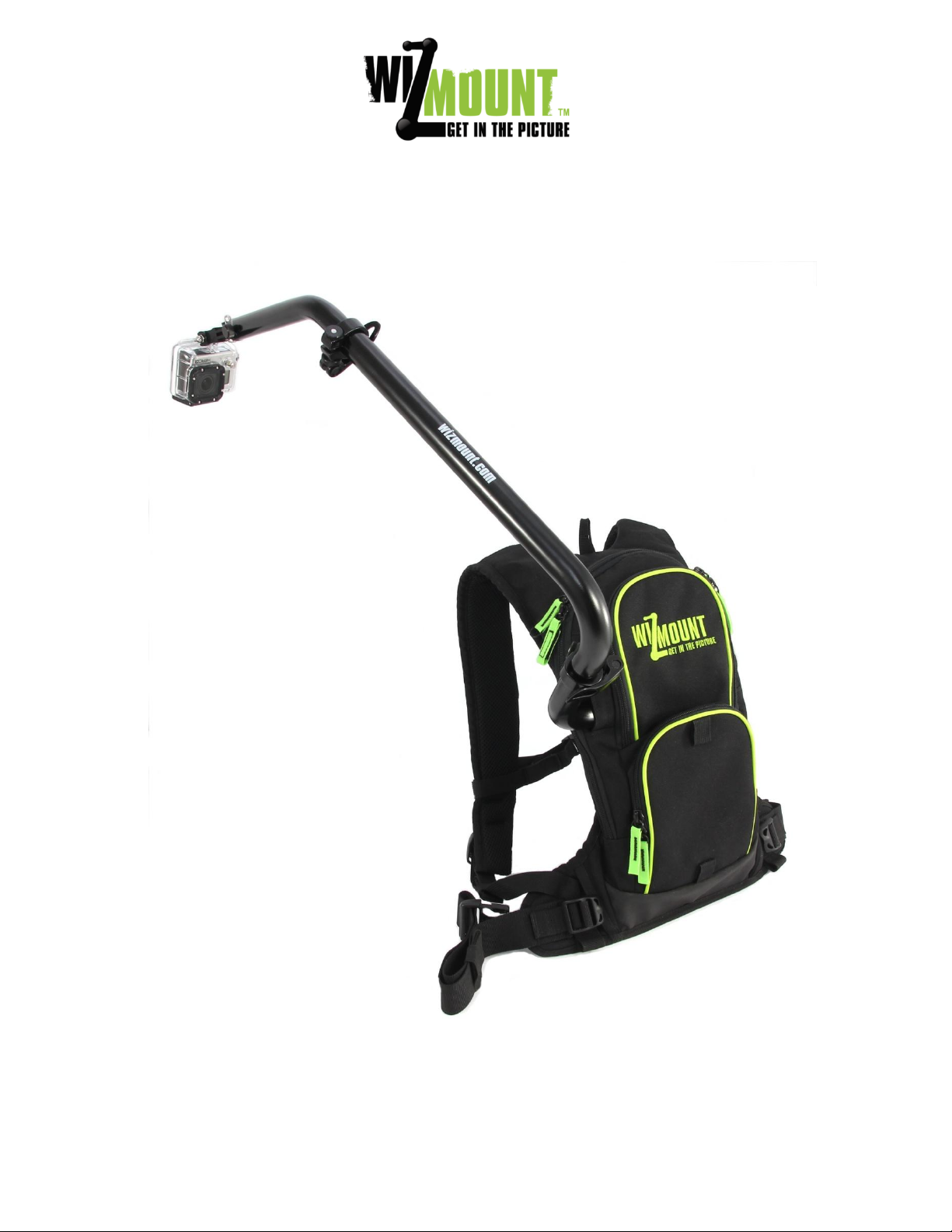
Wizmount CU2pack User Manual
Page 2

Page 2
Table of Contents
System components .......................................................................................................................... 3
Backpack components ....................................................................................................................... 4
Outer components ............................................................................................................................ 4
Poles storage sleeve ...................................................................................................................................4
Inner components ......................................................................................................................................4
System assembly ............................................................................................................................... 5
Adjusting the STAC - “Safety Torque Adjustable Clamp” ..............................................................................7
System assembly (Cont.) ................................................................................................................... 8
Connecting and adjusting your camera ............................................................................................ 10
Mounting other cameras .......................................................................................................................... 11
Adjusting your camera position & angles ........................................................................................ 12
Optional components ...................................................................................................................... 13
300mm Extension Pole (optional) ............................................................................................................. 13
Seat Harness kit (Optional) ....................................................................................................................... 14
Camera securing leash kit (optional) ......................................................................................................... 15
Disassembly .................................................................................................................................... 17
Using your CU2pack as Hydration backpack .................................................................................... 18
Disassembly & Reassembly of the base plate ................................................................................... 19
Maintenance .................................................................................................................................. 20
Page 3
Page 3
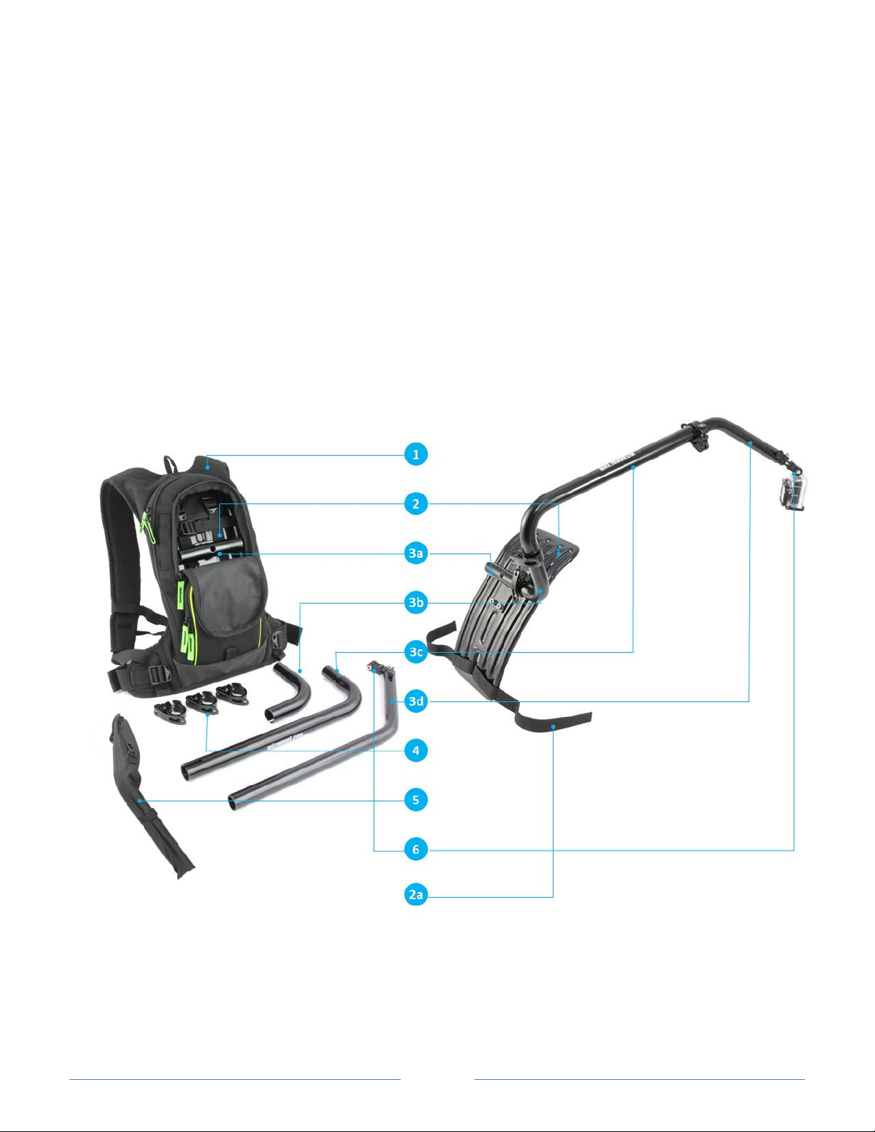
System components
1 Backpack
2 Light weight ergonomic support plate (base plate)
2a Base plate stabilizing straps
3
3a #1 boom pole (base pole, mounted to support plate)
3b #2 boom pole (short 90 deg bend)
3c #3 boom pole (long 90 deg bend)
3d #4 boom pole (45 deg bend)
4 Three Safety Torque Adjustable Clamps (STAC)
5 Poles storage sleeve
6 3-axis camera mount assembly
.
Page 4
Page 4
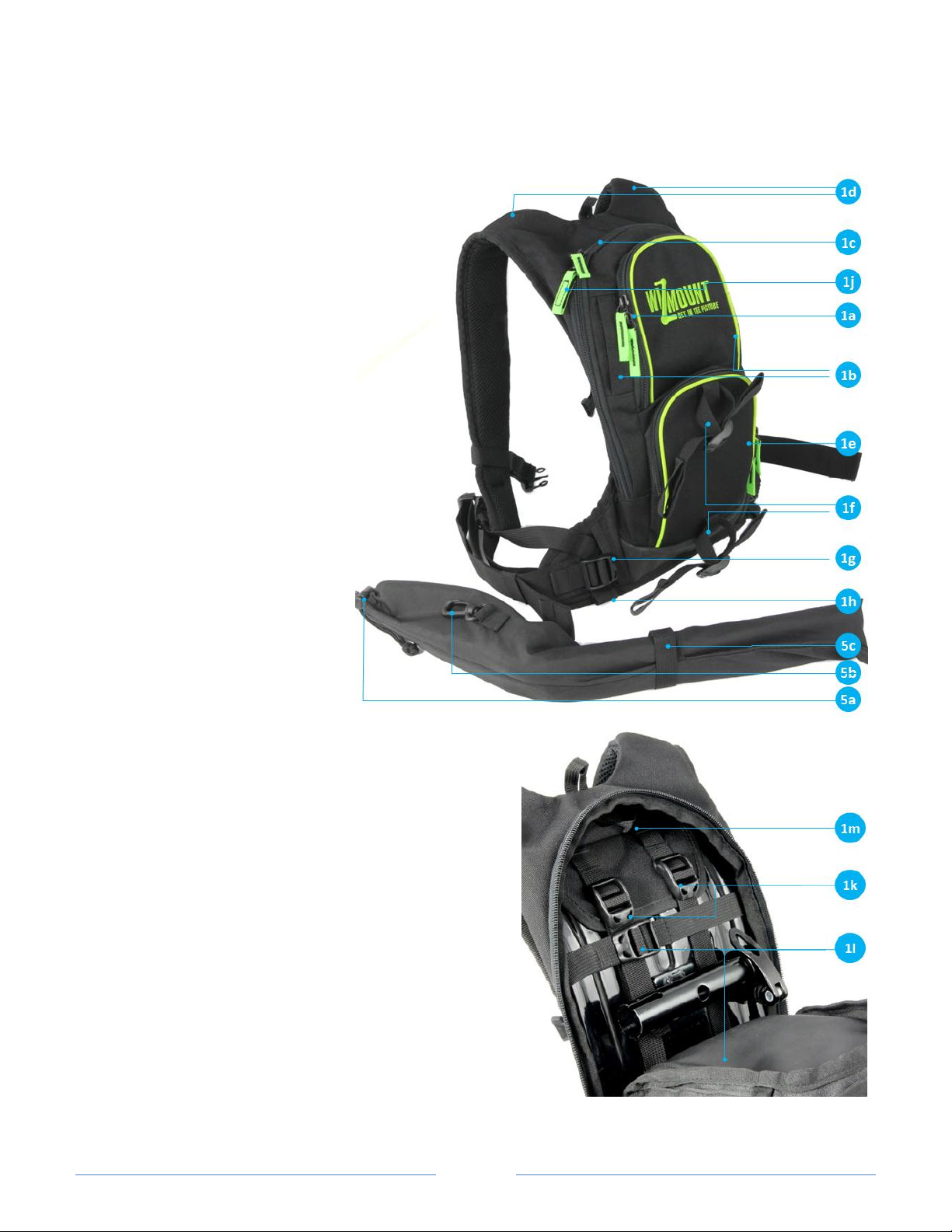
Backpack components
Outer components
1a Top compartment zipper
1b Velcro left & right ports for
poles
1c Main compartment zipper
1d Water tube ports
1e Storage compartment
1f Holding straps for poles
storage sleeve
1g Base plate stabilizing straps
buckle
1h Webbing loop for harness
kit
1j Zipper pull Velcro
Poles storage sleeve
5a Sleeve cord lock
5b Sleeve hook
5c Sleeve Velcro
Inner components
1k Plate Inner harness vertical straps
1l Plate inner harness horizontal straps
(lower strap is hidden in this view)
1m Webbing to hold water bladder
Page 5
Page 5
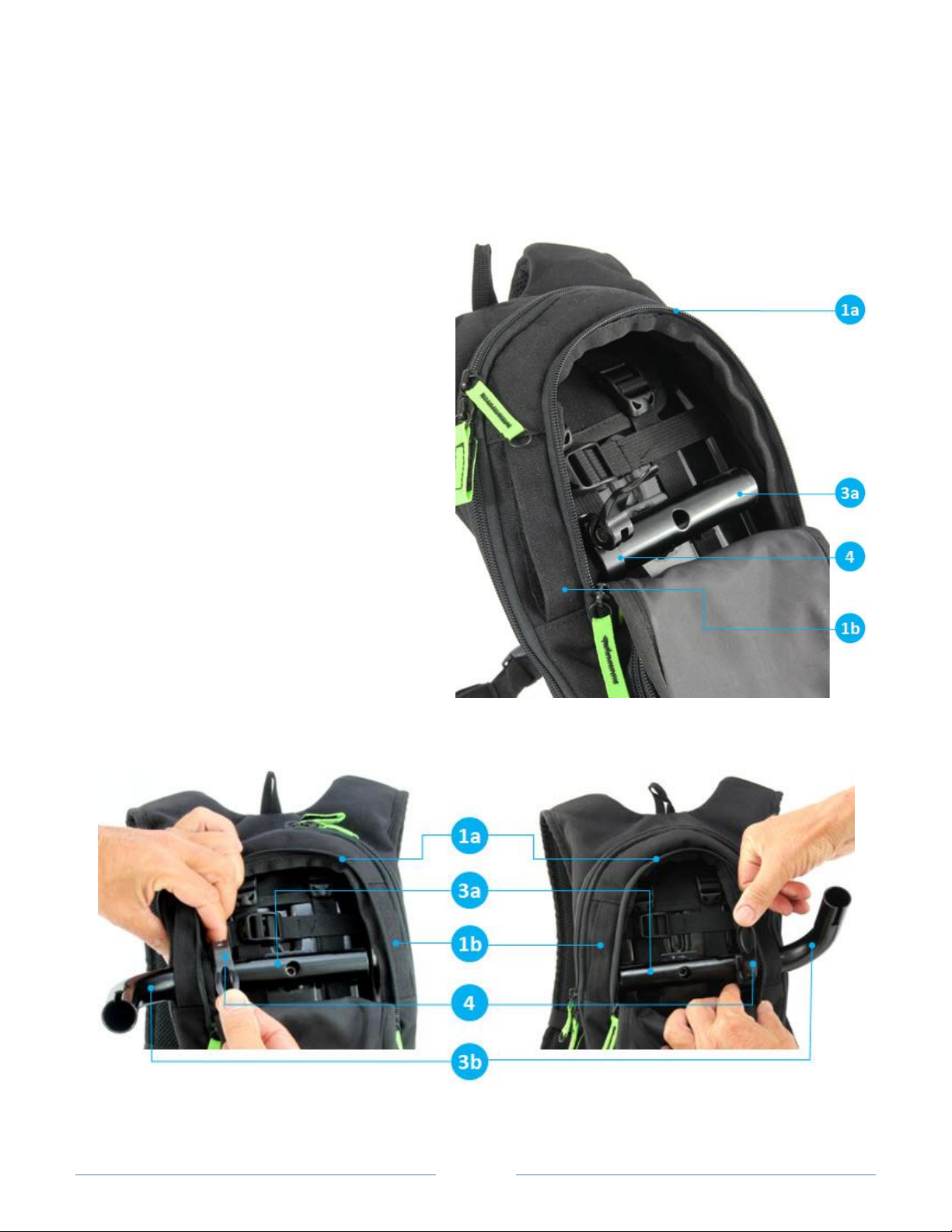
Left hand side assembly
Right hand side assembly
System assembly
1. Open backpack top compartment zipper 1a
(notice that this is the second zipper from top)
2. Place STAC 4 on #1 boom pole 3a left or right
side, according to your preferences, make sure
STAC 4 locking handle is in its open position.
3. Open Velcro port 1b on your preferable side,
left or right.
4. Slide narrow (male) end of boom pole 3b
through the Velcro port into pole 3a
5. Make sure that the reduced diameter section
of pole 3b is fully inserted to pole 3a
6. Push and lock STAC handle until it touches the
clamp body
7. Follow “Adjusting the STAC” instruction
chapter as how to adjust clamping force on
page 7
Page 6
Page 6
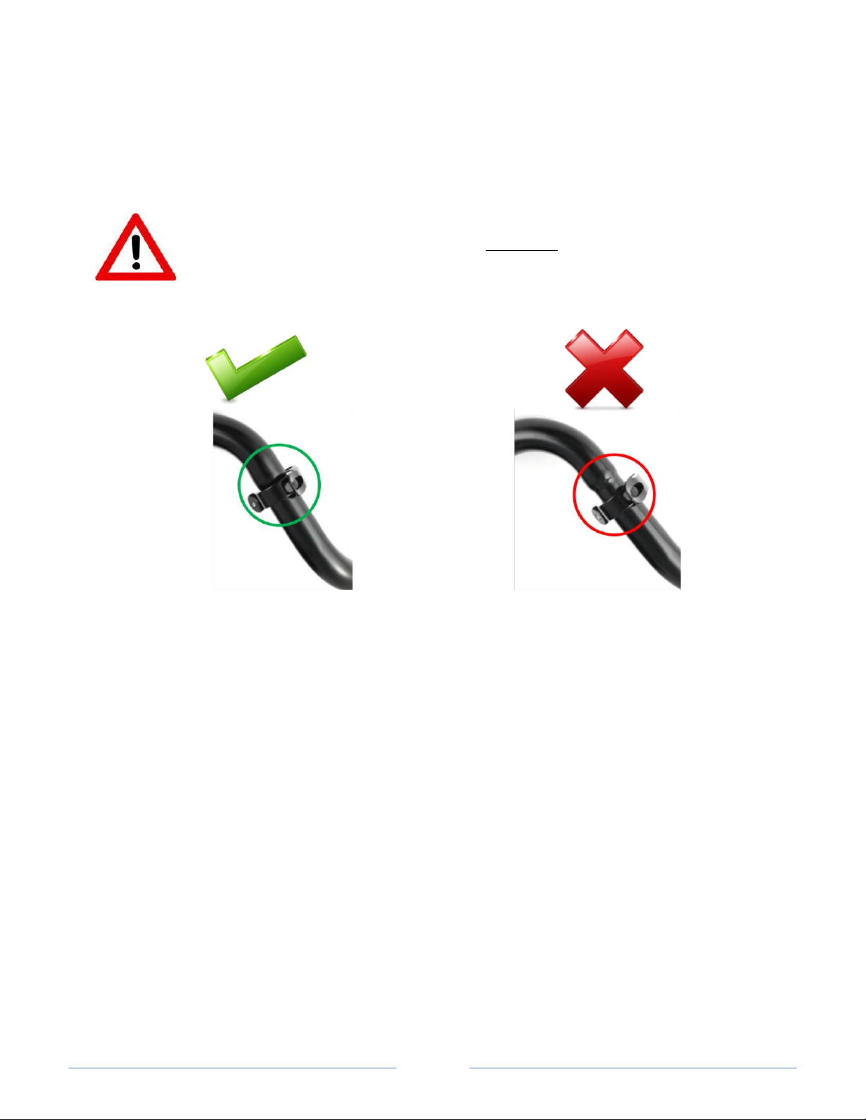
Note 1: One side of STAC 4 has a reduced diameter (see next page) and should be mounted on the boom
Correct assembly
Wrong assembly
pole from its wider diameter side. Therefore, when moving the STAC from left to right side (and vice versa)
on #1 boom pole, STAC should be flipped to its other side
Note2: Tighten STAC only when they are clamping two matching boom poles (Do not clamp a high level of
pressure to STACs when they are clamped to a single pole )
Warning: Failing to insert the assembled poles completely, can result in system damage due to
insufficient overlap between the two poles
Page 7
Page 7
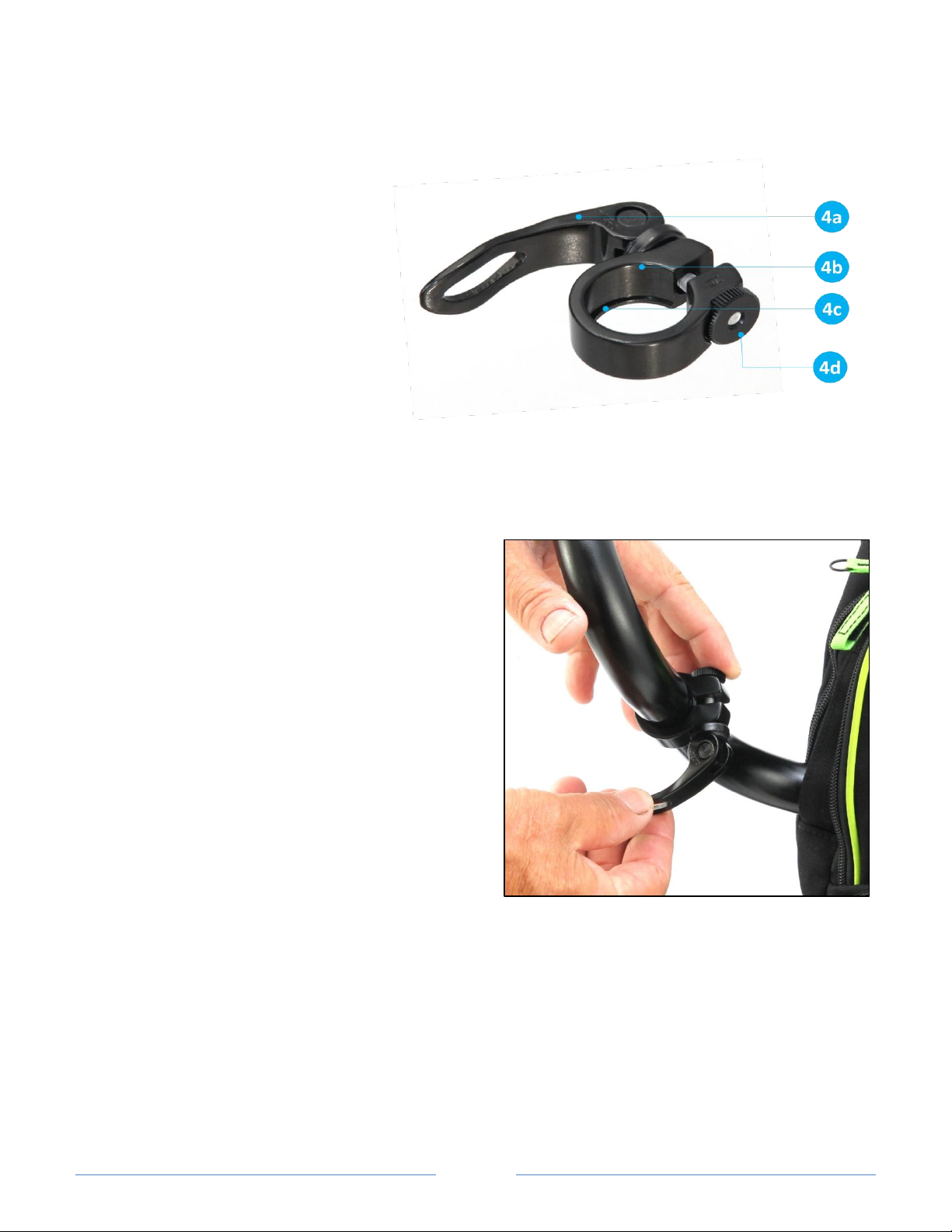
Adjusting the STAC - “Safety Torque Adjustable Clamp”
STAC 4 structure:
4a Quick release handle
4b Clamp insert side
4c Clamp limiter
4d Clamping force adjustment nut
Make initial adjustment of the STAC clamping force by rotating the STAC nut 4d clockwise (to increase
clamping force) or counter clockwise (to decrease clamping force)
Insert clamp, through 4b side, to the pole wider diameter side, until it reaches its limiter 4c
Hold STAC with one hand (to keep it from rotating around the pole) while closing its quick release
handle with your other hand.
If you feel that you need to apply too much force to close the handle, fully open the handle, slightly
rotate (counter clockwise) the clamp nut 4d and
try again to close it again.
If you feel that you need to apply very light force
to close the handle, fully open the handle, slightly
rotate (clockwise) the clamp nut 4d and try again
to close it.
Clamp nut 4d controls the clamping force of the
STAC. Higher clamping force is required for
aggressive maneuvers and will require higher
force to close the quick release handle
After closing the quick release handle, try to
rotate the connected poles one relative to the
other. If they move by applying relatively light
force with your hands, it indicates that clamping
force is not strong enough and should be adjusted
as explained above.
Note: When locking the STAC onto one pole (without
the second matching pole), be sure to adjust the clamp nut for a light clamping force. Use a larger amount of
clamping force only when clamping 2 poles together.
Page 8
Page 8
System assembly (Cont.)
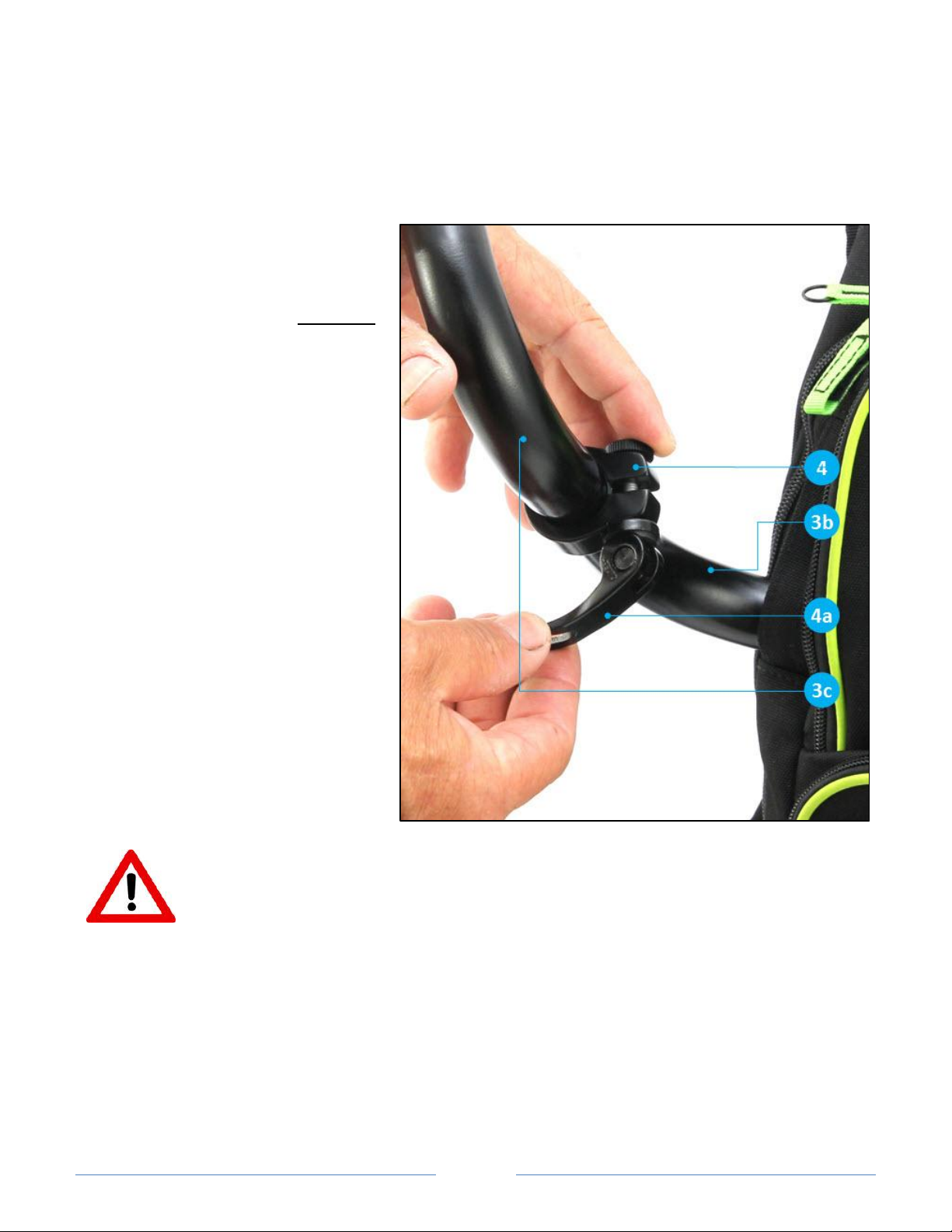
Insert second STAC 4 on part 3b,
make sure the quick release handle 4a
is open. Insert the smaller end of
boom pole 3c into pole 3b completely,
then follow “adjusting the STAC”
instructions.
See page 7 for correct STAC
adjustment
Warning: Failing to insert the pole 3c completely into pole 3b, can result in damage to the system
or opening of the connection between the two poles
Page 9
Page 9
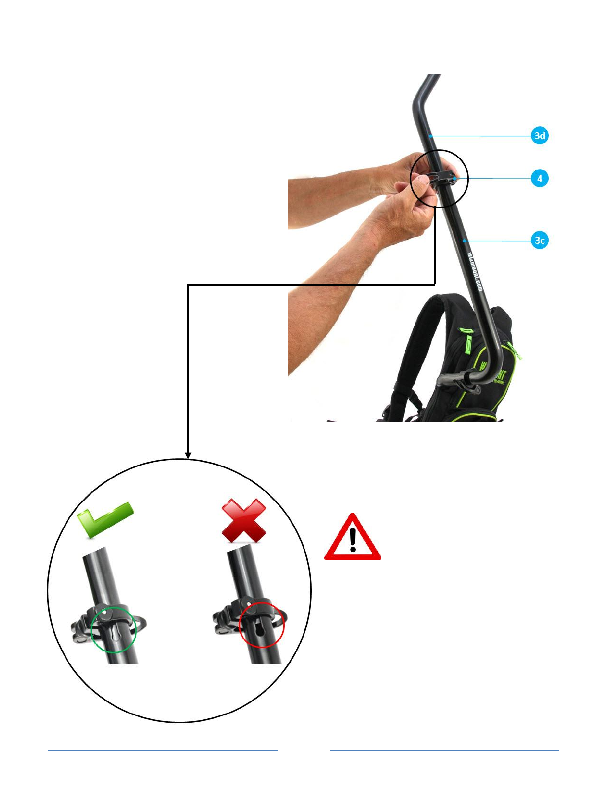
Insert the third STAC 4 on pole 3c, make sure
quick release handle is open. Insert pole 3d
into pole 3c, adjusting it to the required length
and orientation.
Warning: Assembled poles 3c and
3d must overlap at least 40mm
(1.6") which is indicated by pole 3d
completely fills the slit in pole 3c.
Failing to do so, can result in damage to the system
or opening of the connection between the two
poles
Page 10
Page 10
Connecting and adjusting your
camera
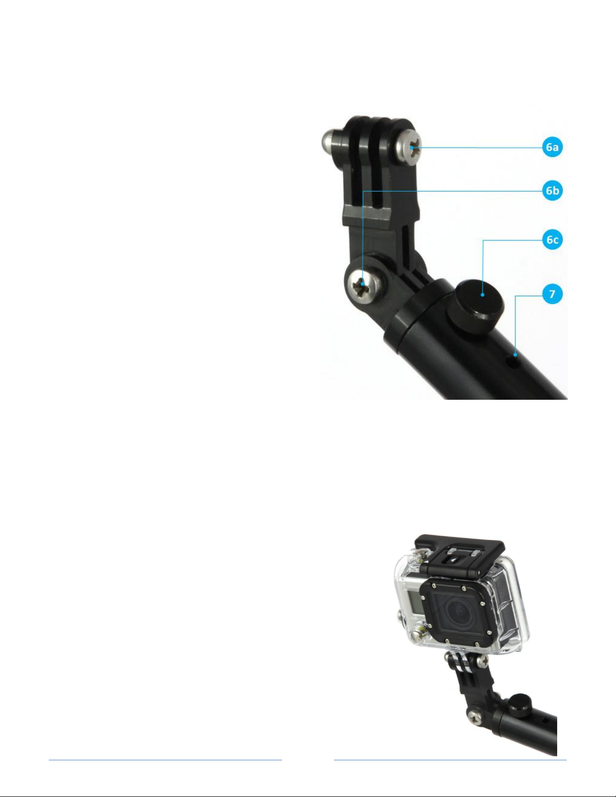
The three way camera assembly provides 3 motion axis
to adjust your camera angles:
6c Pan control with special Wizmount thumb knob
6b Roll axis control with stainless steel bolt
6a Tilt axis control with stainless steel bolts
7 Leash outlet to secure your camera (leash kit is
optional)
Special Wizmount pan adjustment thumb knob 6c
has two functions :
1. Securing the camera assembly mounts to pole 3d
2. Locking the pan axis at the desired angle
Note: The thumb knob 6c has a special safety mechanism that ensures it cannot be fully unscrewed and
removed. Do not try to remove it by applying strong force as you will break the safety mechanism
Mounting of GoPro Hero 1,2 and 3
1. Unscrew bolt 6a and take it out
2. Insert GoPro Camera.
3. Replace bolt 6a and tighten it for the desired camera angle.
Notes:
1. As Wizmount mount assembly is made from Aluminum Alloy and is
more rigid then plastic, it requires slightly more force to enter the
camera house to the tilt control mount compared to GoPro mounts
2. Bolts 6a and 6b are fully compatible with GoPro Knobs.
Nevertheless, to achieve strong and stable camera mounting, we
recommend using Philips screwdriver even if you are using the
GoPro knob.
Page 11
Page 11
Mounting other cameras
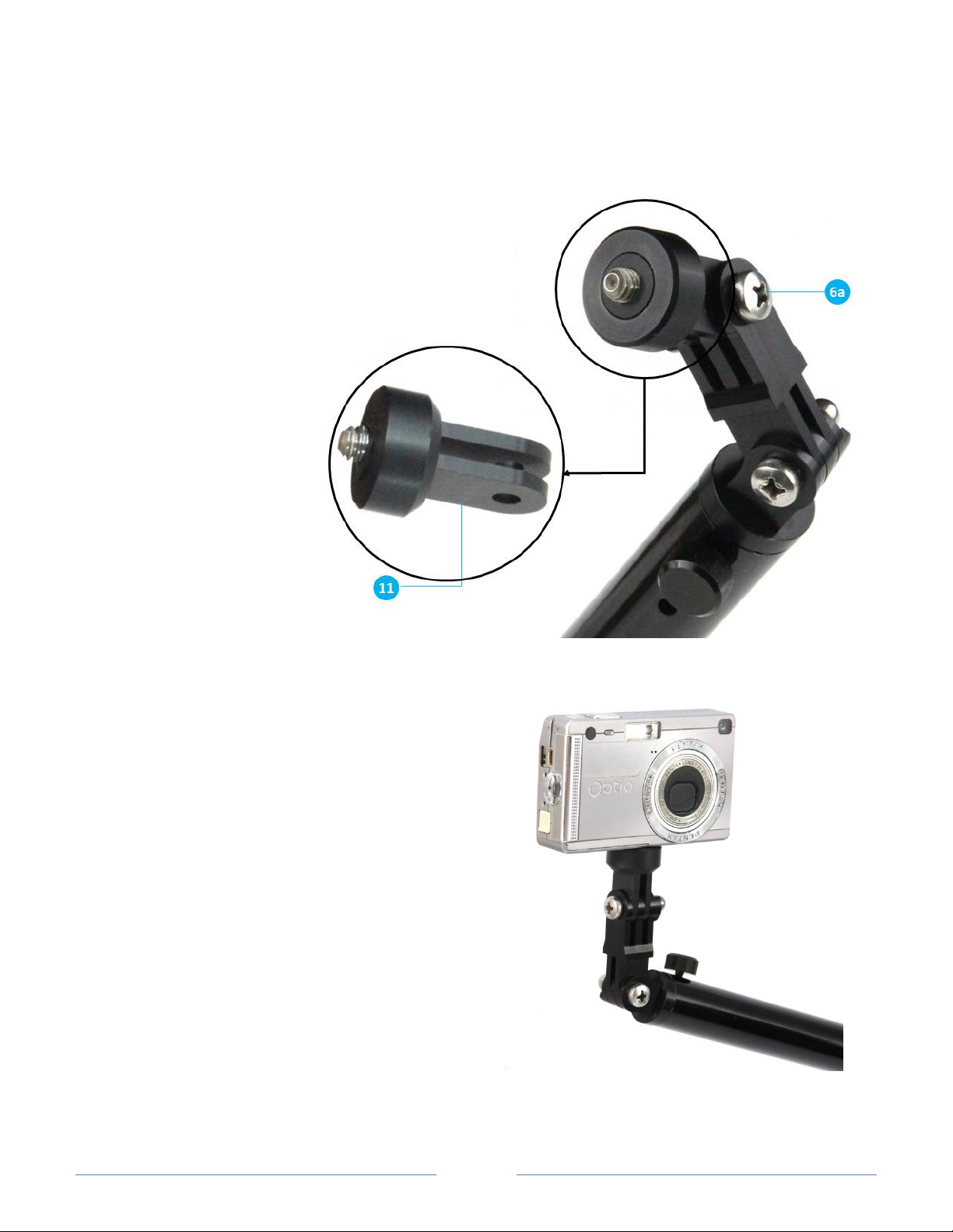
To mount other cameras that
accept a standard 1/4" 20 tpi
(threads per inch), use the
optional universal camera
mount adapter 11.
1. Open bolt 6a, insert
adapter 11, and screw back
the bolt.
2. Insert camera female
thread ¼” to the adapter
bolt and rotate the camera
until locked
Page 12

Page 12
Adjusting your camera position & angles
1. Assemble the whole system with your camera as explained in previous sections
2. Adjust camera position using the 3 joints. Start with the first joint (connects 3a-3b) that is located inside the
pack. Then adjust the second joint (connects 3b-3c) and finally adjust the third joint (3c-3d) that controls
system length as well as orientation.
3. Wear the backpack and fasten the waist strap. Look at the system and camera and roughly check if you
achieved the desired POV (Point Of View). If not, remove the backpack, re-adjust the joints and repeat this
step.
Note: Take your time in the first few times that you use the system to practice different camera positioning by
changing the orientations between the poles. Take into consideration, that the first joint setting, is affecting the
motion of the second joint, and therefore you may find it a bit tricky in the first usage. Once you practice, it will
become easier to use.
4. Once the camera seems to be in the right position, adjust camera angles using 6a, 6b and 6c bolts
5. Operate the camera and watch its image by smart phone or other means supplied by the camera maker. If
such means are not available, we suggest that in the first times, you operate your camera and watch the
recorded result.
6. Once you are satisfied with the POV, make sure that all clamps are fastened enough and that camera
assembly bolts are fasten with a screwdriver.
Note: When you check the camera image, make sure to position your body as if you are doing your sport (for
example, if your are biking, seat on the bike in a riding position, and check the image)
Page 13
Page 13
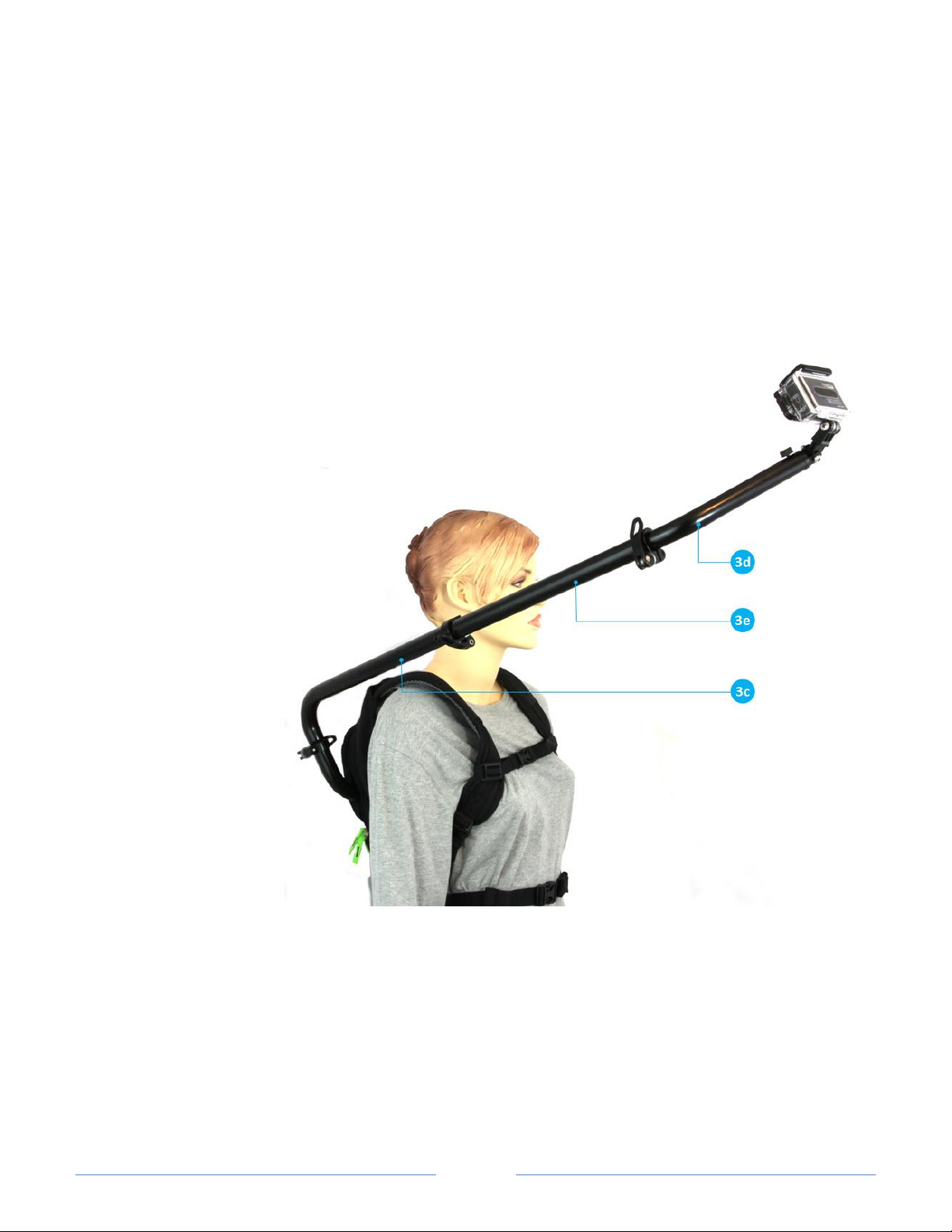
Fig.A - 300mm extension typical assembly
Extension pole used for front shooting
Optional components
300mm Extension Pole (optional)
Expand your reach by using the 300mm boom pole 3e (supplied with one STAC). Especially useful for shooting in
front angles (biking, ski, etc.). In most cases, when shooting from non-front sides, there is no need for the
extension pole.
In most cases, extension
pole should be inserted
between pole 3c and 3d,
however it can be
inserted between any
other poles pair (e.g. 3a3b or 3b - 3c)
Page 14
Page 14
Waist Harness kit (Optional)
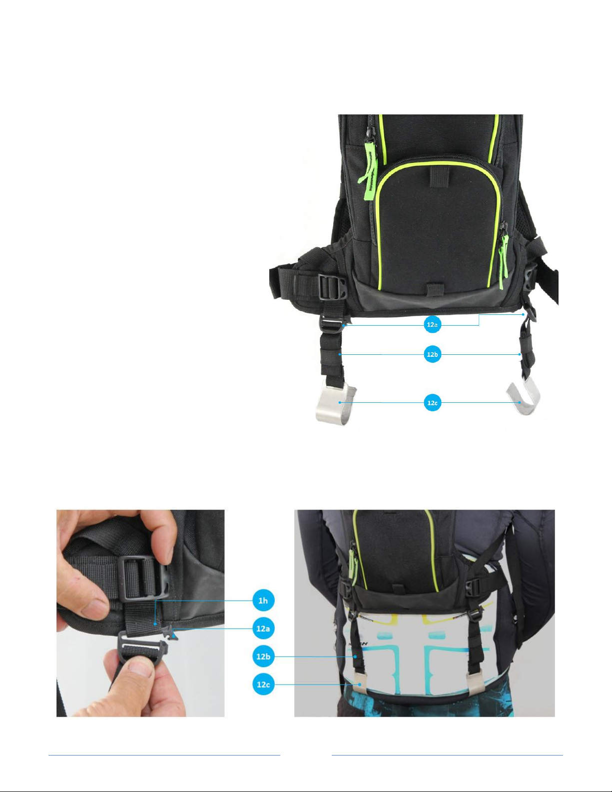
Designed to be used in sports where a waist
harness is used (kitesurfing, windsurfing,
snowkiting, etc.). Keeps the CU2pack from
riding up on your back while surfing. The
waist harness kit clips on the bottom of your
waist harness to stabilize and keep the
CU2pack in place.
The kit includes:
12a 2 special buckles
12b 2 40cm straps
12c 2 stainless steel clips
Assembly instructions
Open the top part of the special buckles 12a
and slide them through the backpack
webbing loops 1h. Close the buckle to lock it
to the webbing.
After wearing and adjusting your harness, wear the backpack, and clip the stainless steel clips 12c to the bottom
of your harness. Fasten straps 12b so the backpack is pulled towards harness bottom
Note: Clips 12c have some flexibility. If your harness is thicker than their opening, you can increase the gap of
their opening by holding both sides of the clip and slightly pulling apart.
Page 15
Page 15
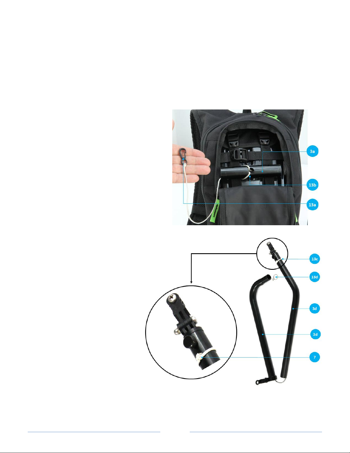
Camera securing leash kit (optional)
Leash short cord assembly
Leash short cord assembly
Leash long cord assembly
Built from 2 separate cords to enable easy dismantling and assembly of the system, the leash kit is designed to
secure your camera as well as all CU2pack components. The leash runs through the inside of all boom poles and
attaches your camera (via a dedicated leash outlet) to the backpack support plate. We highly recommend using
the leash at all times, especially during water sports.
Assembly instructions
Short cord section
1. Insert the short cord loop 13b through one of
the pole 3a sides and pull it out through the pole
center hole
2. Slide the loop around pole opposite side to get a
secure connection of the cord to the first pole
Long cord section
1. Slide the long cord loop 13c along
pole 3d until you reach the leash
outlet 7
2. Insert the other side of the long
cord into the leash outlet and pass
it through Pole 3d and 3c (with
clamp attached)
3. Tie the cord end to the metal ring
13d
Page 16
Page 16
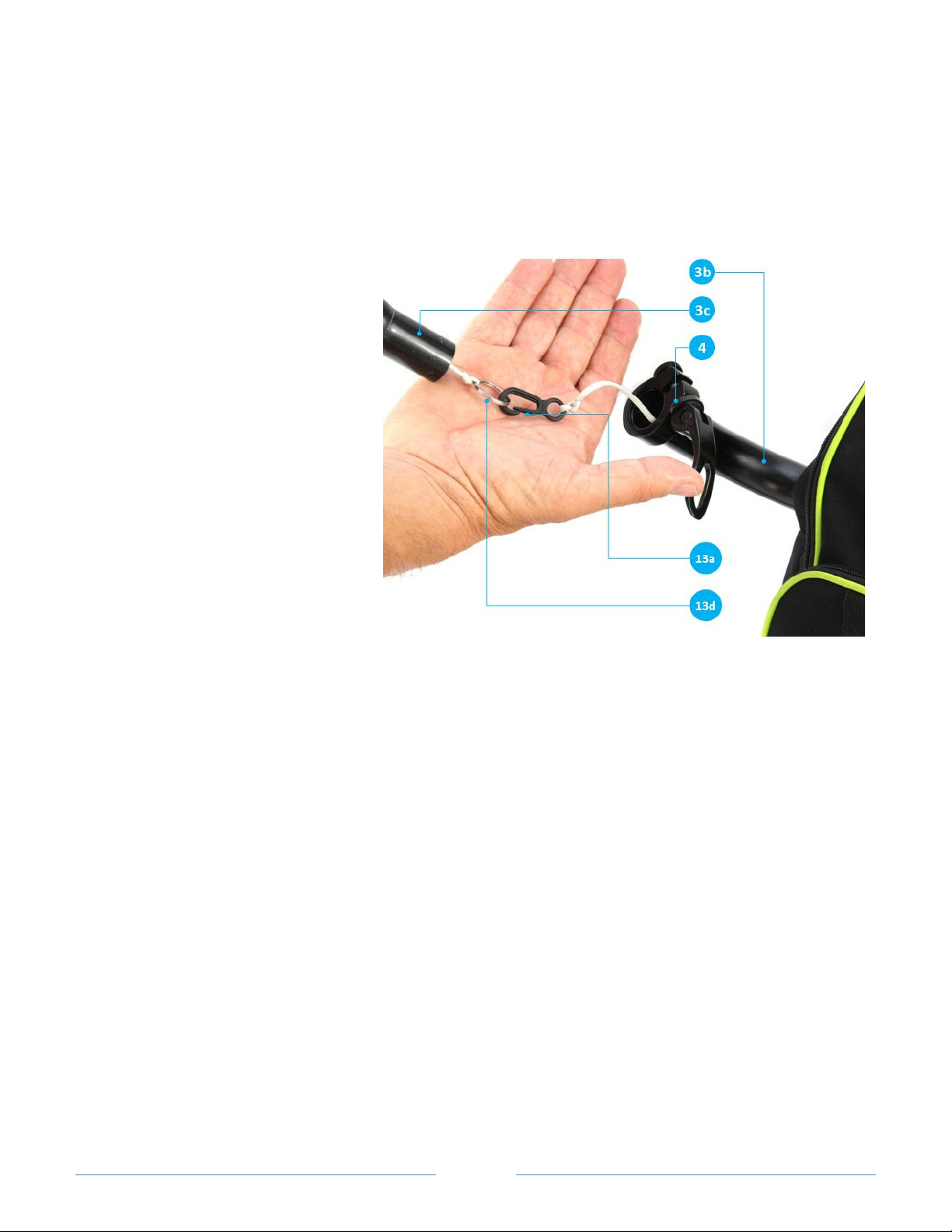
Connecting the two leash sections
1. Insert the hook 13a through the first
pole 3a STAC 4 (not shown in the
picture), pole 3b and another STAC
4.
2. Connect the hook 13a to the metal
ring 13d
3. Insert pole 3c to pole 3b (metal ring
should be pushed to pole 3b)
4. Lock STAC 4
Page 17
Page 17
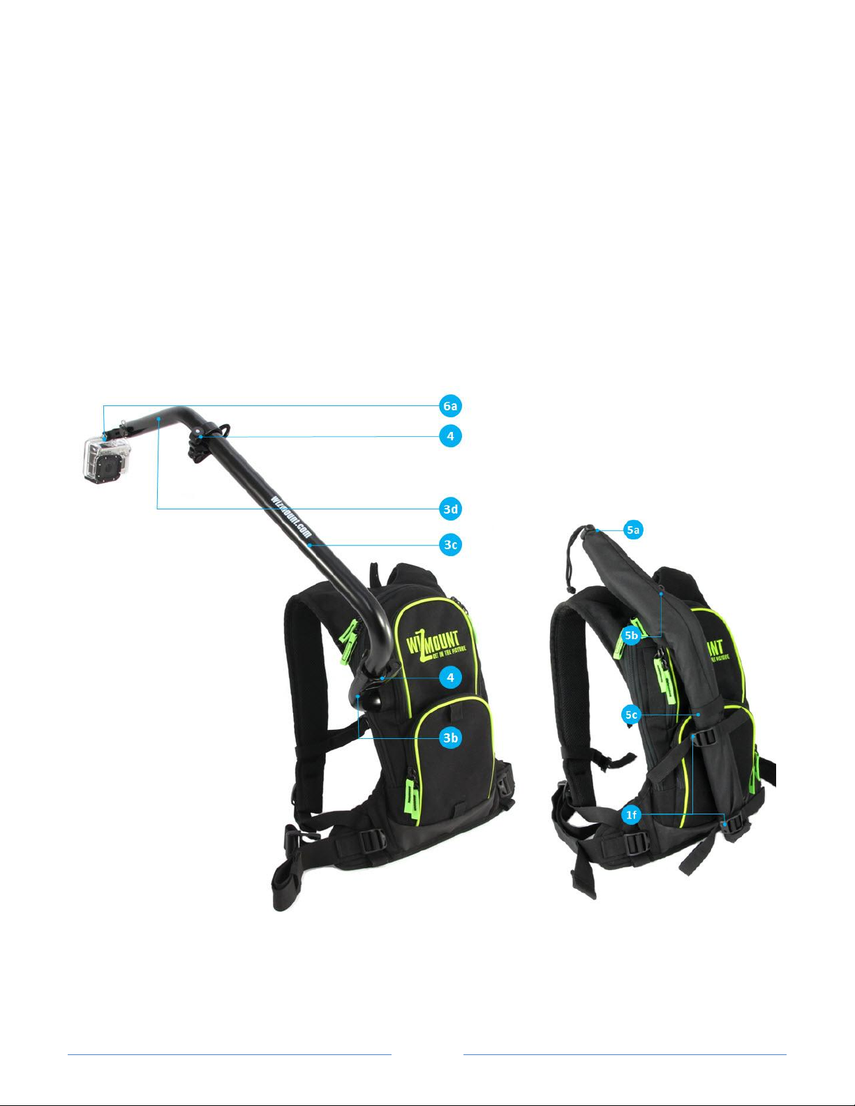
Disassembly
When the CU2pack is not in use, you can disassemble the system and store all components within the backpack
or inside the supplied poles storage sleeve
Poles disassembly instructions using the external sleeve:
1. Disconnect your camera by opening bolt 6a
2. Open STAC 4 between poles 3c-3d and 3b-3c
3. Disconnect poles 3c and 3d and insert them into sleeve 5. Fasten it's cord lock 5a and its Velcro 5c
4. Disconnect pole 3b and insert it and STACs to one of the backpack compartments
5. Attach the sleeve to the backpack by using 1f sleeve holding straps and secure it by attaching the sleeve
hook 5b to the top hanging webbing of the backpack
Page 18
Page 18
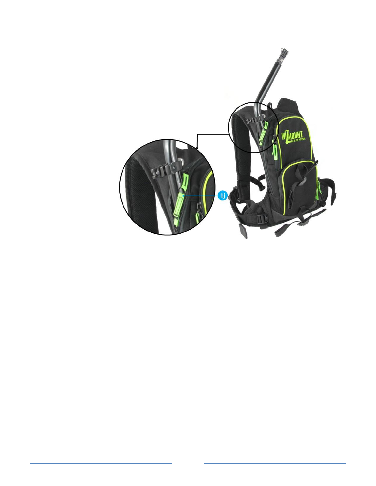
Poles disassembly instructions without a sleeve:
1. Disconnect your camera by opening bolt 6a
2. Fully retract pole 3d into pole 3c
3. Open pole 3c-3b STAC 4 and disconnect the pair 3c-3d from 3b pole
4. Insert poles 3c-3d to backpack main compartment as seen in the picture
5. Insert the STACs to one of the backpack compartments
6. Secure the backpack main zipper by opening 1j Velcro and inserting it
to the second zipper pull tab (see zoomed picture)
Using your CU2pack as Hydration backpack
With plate & poles
You can add a water bladder (approx. 1 liter) to the backpack, while using the system for camera shooting. Use
CU2pack water bag webbing 1m to hang water bladder inside the backpack. Take bladder tube out through left
or right water tubes outlets 1d.
Without plate & poles
For storing larger amount of water and/or additional items, you may disassemble the base plate from the
backpack and use it as a standard high quality hydration backpack. Follow the instruction in the next section
"Disassembly & Reassembly of the base plate".
Page 19
Page 19
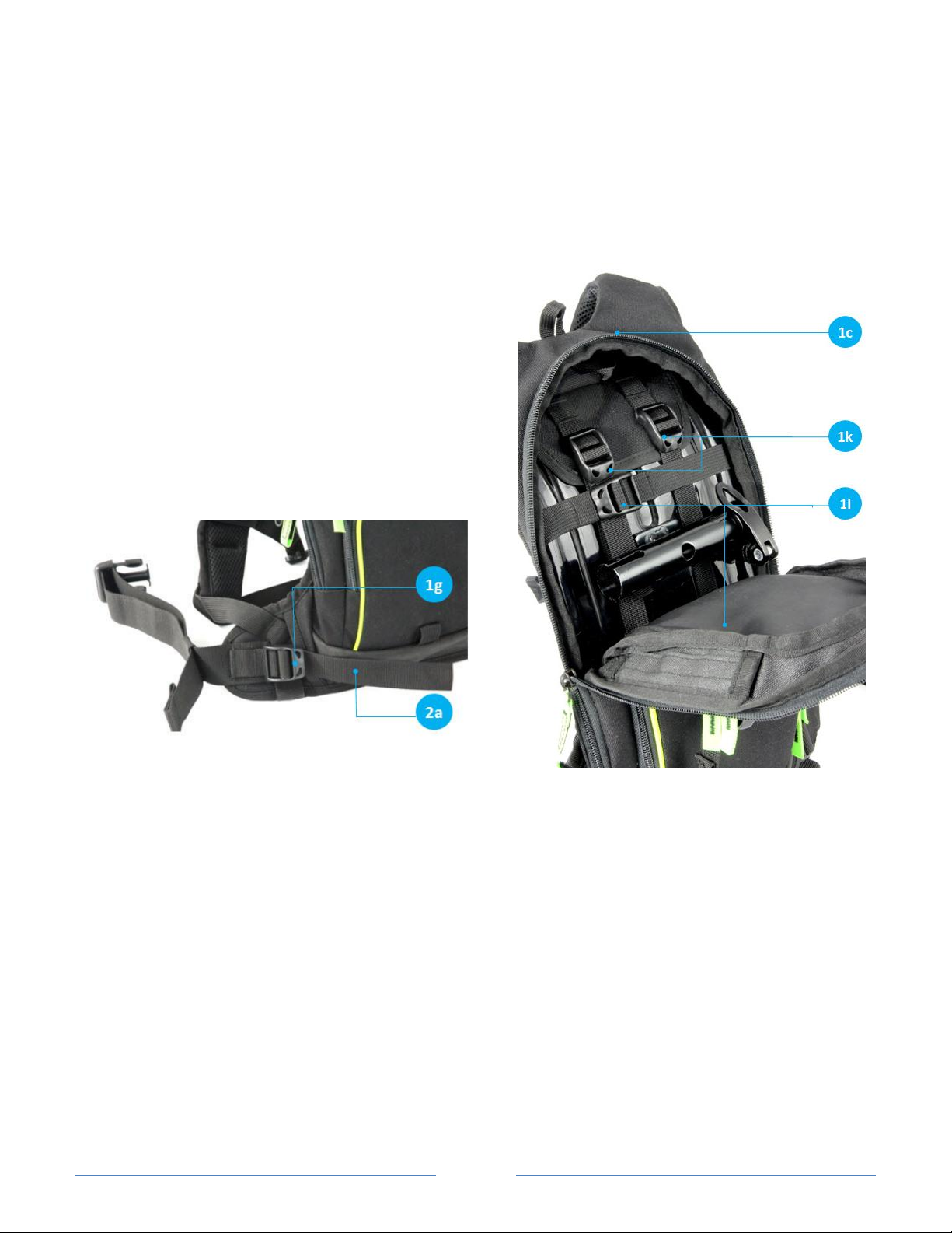
Disassembly & Reassembly of the base plate
Disassembly
1. Release all poles from backpack
2. Release and remove the base plate holding straps 2a
from buckle 1g
3. Completely open main zipper 1c
4. Completely open vertical plate straps 1k
5. Completely open horizontal plate straps 1l
6. Take the plate out
Assembly
1. Open main zipper 1c completely down
2. Move the inner harness straps (1k, 1l) to the sides and insert the plate
3. Insert your hand to the bottom of the base plate and pull base plate stabilizing straps 2a through right and
left backpack waist straps outlets.
4. Run the base plate stabilizing straps 2a through 1g buckles and make initial fastening
5. Close inner harness vertical straps 1k. Make sure base plate is in correct position and tighten the 1k straps
6. Close inner harness horizontal straps 1l. Make sure base plate is in correct position and tighten the 1l straps
7. Make final fastening of all straps: 1k, 1l and 2a. Make sure that plat seats tightly inside the backpack.
8. Close the main zipper 1c
Page 20

Page 20
Maintenance
Rinse the system with fresh water after every use in seawater. Store it after drying it completely.
Avoid disassembly of the system in sand. If sand gets inside the overlapping area between the poles, make
sure to disassemble the poles, clean the sand, and reassemble the clean poles
When storing the system for a long period of time it is recommended to disassemble the poles
Periodically check and tight, if needed, the inner harness base plate straps 1k and 1l and base plate holding
straps 2a. Loose straps may lead to unstable system.
 Loading...